
HVLF32X - Flash SONY - Free user manual and instructions
Find the device manual for free HVLF32X SONY in PDF.
| Product type | Electronic flash for digital camera |
| Brand | Sony |
| Model | HVLF32X |
| Dimensions (L x H x D) | 77 × 91 × 99 mm (3 1/8 × 3 5/8 × 4 inches) |
| Weight | Approx. 260 g (9.2 oz) |
| Power supply | 4 AA alkaline batteries (6 V DC) |
| Guide number (ISO 100, 1/1) | 32 (without wide-angle diffuser) / 22 (with diffuser) |
| Flash coverage | 28 mm (35 mm equivalent); wide angle with included diffuser |
| Flash modes | AUTO A, AUTO B, MANUAL |
| Bounce flash | Yes, positions 45°, 60°, 75°, 90° upward |
| AF illuminator | Yes, adjustable (normal, high, off) |
| Pilot lamp | Yes (shadow checking pre-flash) |
| Flash test | Yes (via dedicated button) |
| LCD backlight | Yes, timed (10 seconds) |
| Sleep mode | Automatic after 1 minute of inactivity |
| Number of flashes (new batteries) | Approx. 150 (at 20 °C) |
| Cleaning | Soft dry cloth; avoid solvents |
| Safety | Do not expose to rain or moisture; avoid temperatures > 40 °C |
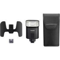
| Supplied accessories | Hot shoe adapter, connecting cord, case, instruction manual |
| Warranty | See manufacturer's terms |
Frequently Asked Questions - HVLF32X SONY
User questions about HVLF32X SONY
0 question about this device. Answer the ones you know or ask your own.
Ask a new question about this device
Download the instructions for your Flash in PDF format for free! Find your manual HVLF32X - SONY and take your electronic device back in hand. On this page are published all the documents necessary for the use of your device. HVLF32X by SONY.
USER MANUAL HVLF32X SONY
To prevent fire or shock hazard, do not expose the unit to rain or moisture. To avoid electrical shock, do not open the cabinet. Refer servicing to qualified personnel only.
IMPORTANT SAFETY INSTRUCTION
When using your electronic flash, basic safety precautions should always be followed, including the following:
1 Read and understand all instructions before using.
2 Care must be taken as burns can occur from touching hot parts.
3 Do not operate appliance if it has been dropped or damaged, until it has been examined by a qualified serviceman.
4 To reduce the risk of electric shock, do not immerse this appliance in water or other liquids.
5 To reduce the risk of electric shock, do not disassemble this appliance, but take it to a qualified serviceman when service or repair work is required. Incorrect reassembly can cause electric shock when the appliance is used subsequently.
6 The use of an accessory attachment not recommended by the manufacturer may cause a risk of fire, electric shock, or injury to persons.
SAVE THESE INSTRUCTIONS
Note:
This equipment has been tested and found to comply with the limits for a Class B digital device, pursuant to Part 15 of the FCC Rules. These limits are designed to provide reasonable protection against harmful interference in a residential installation. This equipment generates, uses, and can radiate radio frequency energy and, if not installed and used in accordance with the instructions, may cause harmful interference to radio communications. However, these is no guarantee that interference will not occur in a particular installation. If this equipment does cause harmful interference to radio or television reception, which can be determined by turning the equipment off and on, the user is encouraged to try to correct the interference by one or more of the following measures:
— Reorient or relocate the receiving antenna.
— Increase the separation between the equipment and receiver.
- Connect the equipment into an outlet on a circuit different from that to which the receiver is connected.
— Consult the dealer or an experienced radio/TV technician for help.
You are cautioned that any changes or modifications not expressly approved in this manual could void your authority to operate this equipment.
For the customers in Germany
Directive: EMC directive 89/336/EEC, 92/31/EEC
This equipment complies with EMC regulations when used under the following circumstances:
Residential area
Business district
Light-industry district
Table of contents
Features 5
Caution 6
Cleaning 6
Parts identification 7
Names and functions of the parts 8
Display panel 9
Installing the batteries. 10
Closing the battery cover. 11
Mounting the flash 12
Using the flash 15
Meaning of READY lamp states 20
Bounce flash photography 21
Mounting the wide panel 23
Return the wide panel to its original position. 24
If the wide panel is detached 24
Power save mode 25
Test flash 26
Modeling flash 27
Connection cord 28
Back light 28
Troubleshooting 29
Specifications 30
Features
- This unit is exclusively for use with digital still cameras with an advanced accessory shoe or ACC terminal made by SONY.
- Using its pre-flash function flash photographs with the correct exposure can be taken.*
- With it's AF illuminator function the auto focus works even in dark locations.*
- There are some types of digital still cameras with which this flash cannot be used.
Caution
The flash cannot be used on camcorders.
- Removing or attaching this unit to a digital still camera while the power is ON, or disconnecting the connection cord while the power is ON can cause the flash to fire erroneously.
- When the flash is used in low-temperature conditions, battery performance is reduced. For example, the number of flashes becomes lower than that in room temperature (about 20^ ), and the charging time becomes longer. We recommend preparing new batteries. Note, however, that even batteries whose performance has dropped due to low temperatures are restored by returning them to room temperature.
- Do not leave or store the flash in temperatures that exceed 40^ . Doing so might adversely affect the internal structure of video flash. (In particular, take care not to leave the flash in automobiles during summer.)
- The nameplate is located on the bottom exterior.
Cleaning
Remove this unit from the digital still camera. Clean the flash with a dry soft cloth. In case of stubborn stains, use a cloth lightly dampened with a mild detergent solution, then wipe the unit clean with a dry soft cloth. Never use strong solvents, such as thinner or benzine, as these damage the surface finish.
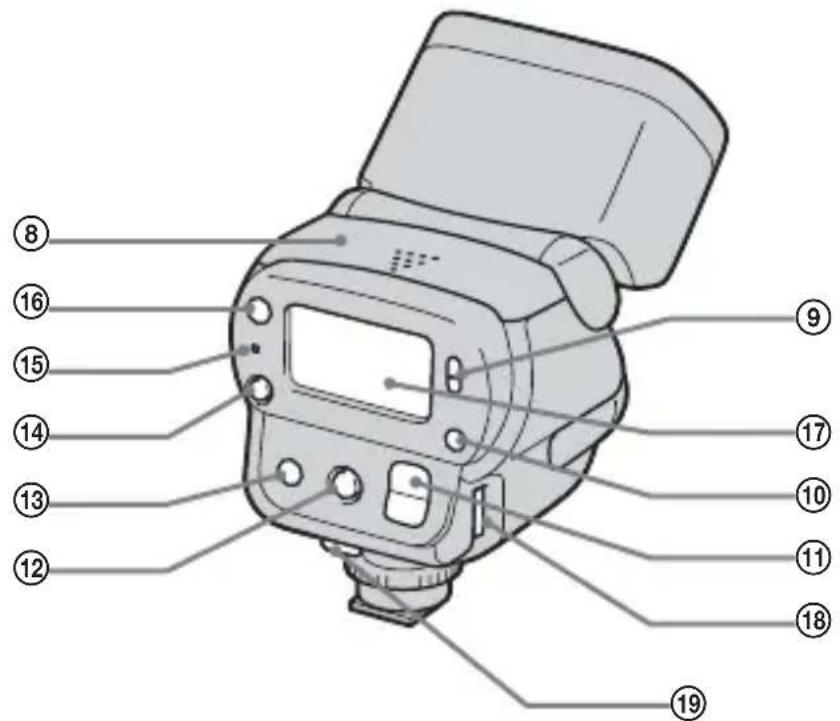
Parts identification
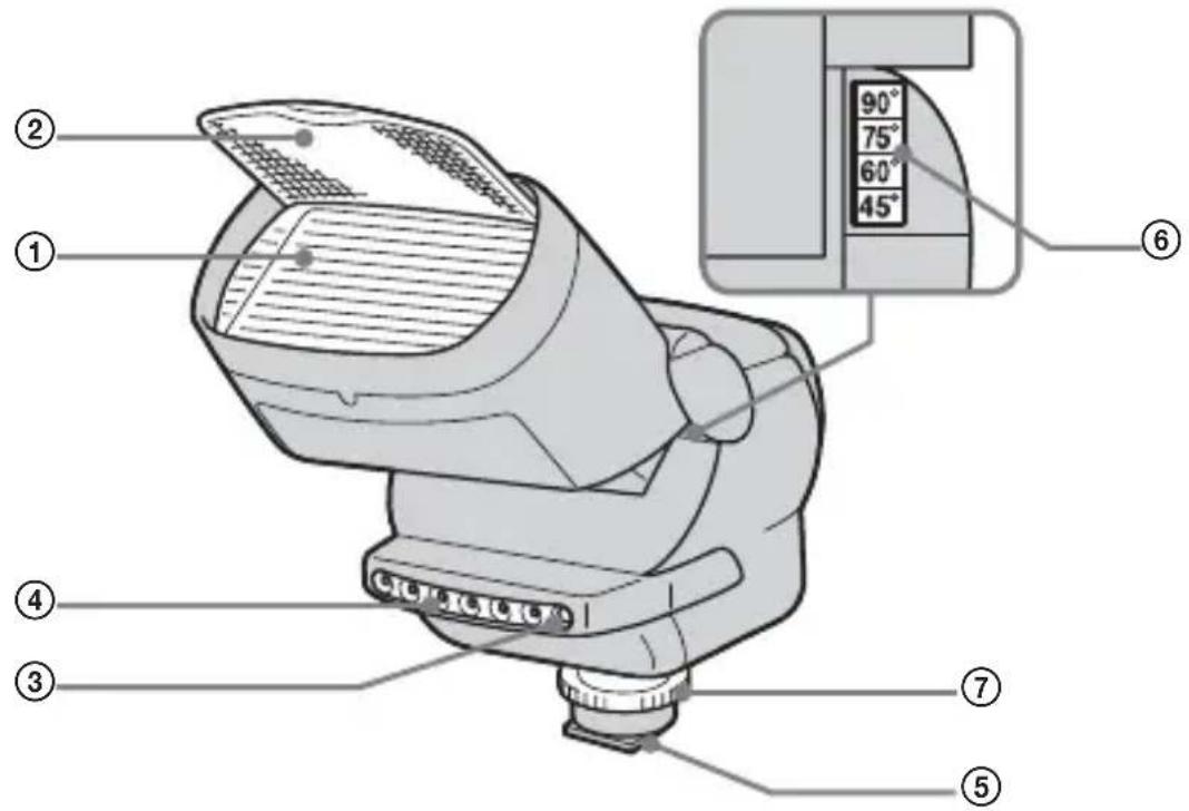
① Flashing section
(2)Wide panel
③ Light exposure meter
④ AF illuminator
(5) Advanced accessory shoe
⑥ Bounce flash angle display
⑦ Rotating knob
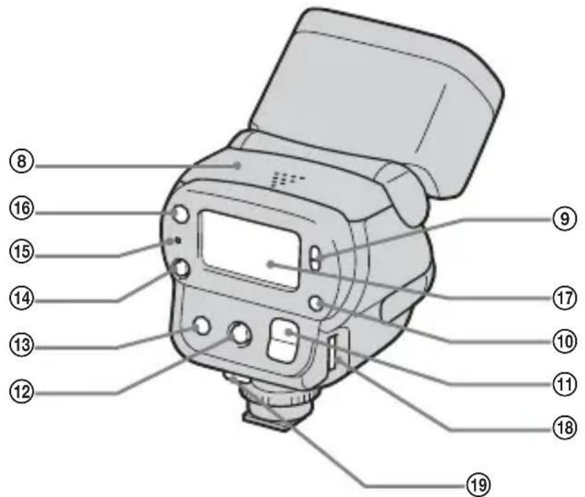
⑧Battery cover
⑨ POWER switch
10Mode button
Light intensity change button
⑫Modeling light button
⑬Back light button
⑭Test flash button
⑤READY lamp
⑥AF illuminator change button
⑦Display panel
Connection cord terminal
⑨ Cord clampers
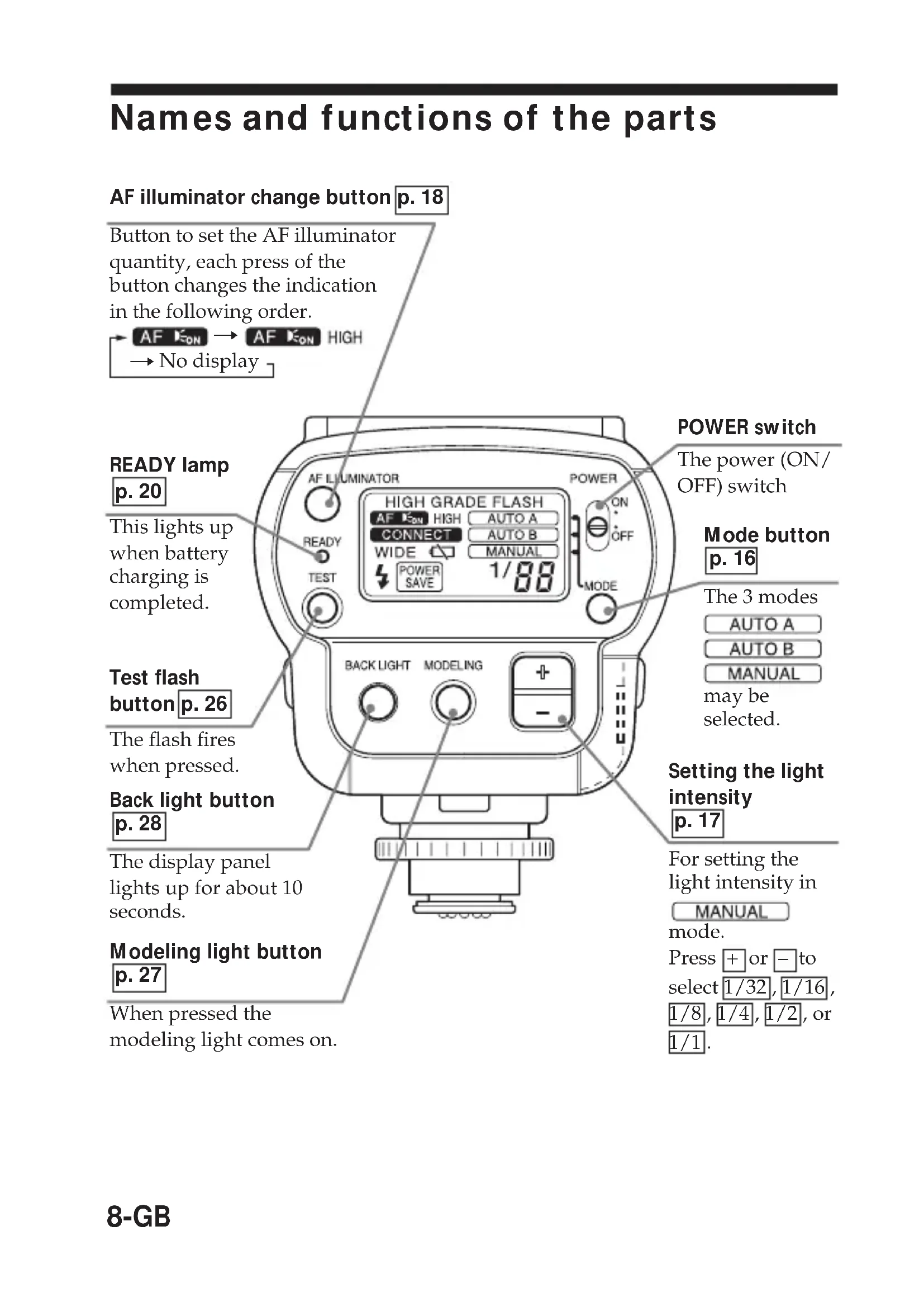
Names and functions of the parts
AF illuminator change button p. 18
Button to set the AF illuminator quantity, each press of the button changes the indication in the following order.

READY lamp p.20
This lights up when battery charging is completed.
Test flash button p. 26
The flash fires when pressed.
Back light button p.28
The display panel lights up for about 10 seconds.
Modeling light button p.27
When pressed the modeling light comes on.
POWER switch
The power (ON/OFF) switch
Mode button p.16
The 3 modes AUTO A AUTO B MANUAL may be selected.
Setting the light intensity p.17
For setting the light intensity in MANUAL mode.
Press + or - to select 1/32, 1/16, 1/8, 1/4, 1/2, or 1/1.
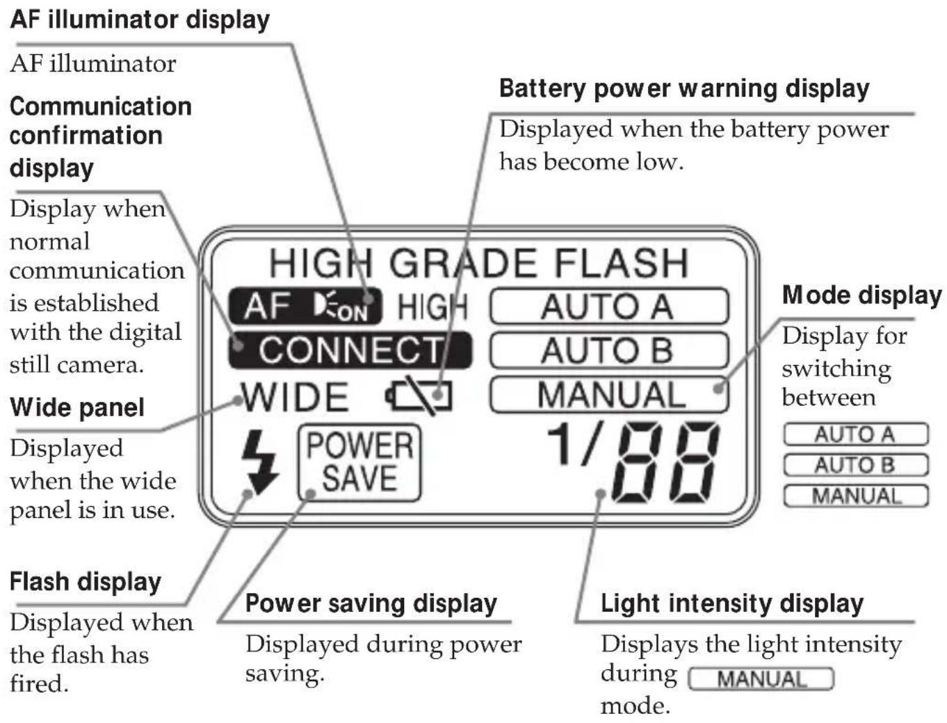
Display panel
Installing the batteries
Use four AA alkali dry batteries.
1 Slide the battery cover to open.
2 Insert the four batteries in the directions marked inside the battery case.
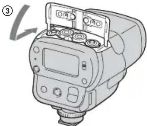
3 Slide back the battery cover to close.
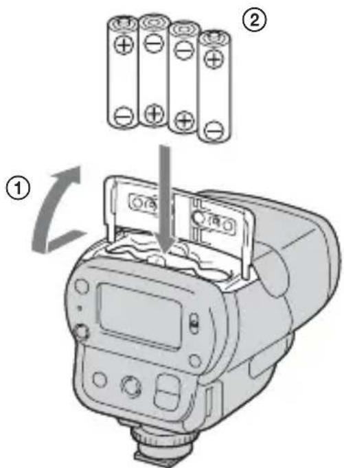
Notes
- Be sure to use four batteries of the same type.
- Be sure to confirm the - poles of the batteries. Inserting the batteries with the poles in the wrong direction may cause leakage or ruptures.
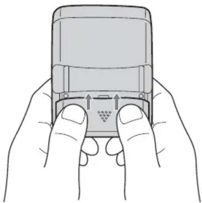
Closing the battery cover
Close pushing both the sides of the battery cover like an illustration, when you slide and close the battery cover.
It can close the battery cover surely.
Mounting the flash
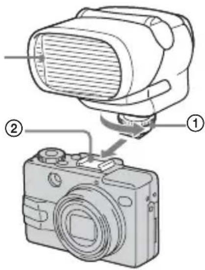
1 When using the digital still camera which is compatible with the advanced accessory shoe

Flashing section
The lock pin moves up and down by turning the rotating knob.

Pin Name
Lock pin
①Turn the rotating knob in the direction of the arrow to loosen.
Raise the lock pin fully.
② Insert this unit into the accessory shoe towards the front, with the flashing section facing forward.
Be sure that the POWER switch is OFF when inserting.
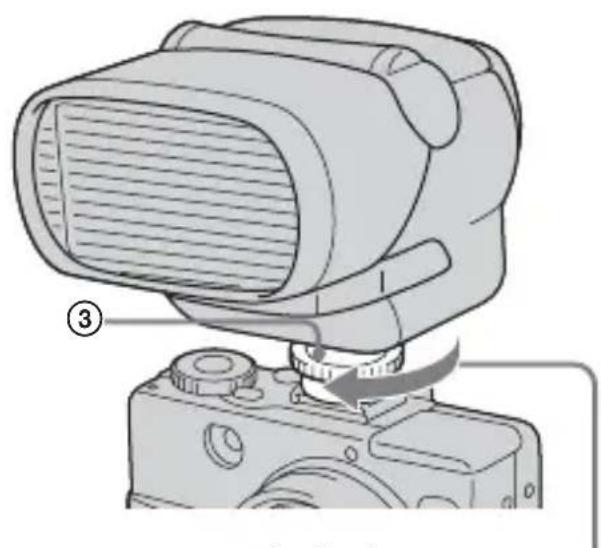
③Turn the rotating knob in the direction of the arrow to tighten.
Lower the lock pin fully. If it is not fully lowered then this unit may fall down.
When attaching or removing this unit from the digital still camera, loosen the rotating knob fully, and raise the lock pin fully.
12-GB
2 When using the digital still camera which is not compatible with the advanced accessory shoe
- Connect this unit to the digital still camera with the supplied connection cord.

①Turn the rotating knob in the direction of the arrow to loosen.
② Insert this unit into the accessory shoe towards the front, with the flashing section facing forward.
③Turn the rotating knob in the direction of the arrow to tighten.
④ Attach the connection cord to the connection cord terminal of this unit.
⑤Connect the connection cord to the ACC terminal of the digital still camera.
*Depending upon the digital still camera being used, fix the connection cord by pressing it between the cord clampers.
Note
Removing or attaching this unit to a digital still camera while the power is ON, or disconnecting the connection cord while the power is ON can cause the flash to fire erroneously.
Mounting the flash (continued)
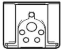
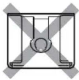
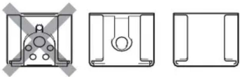
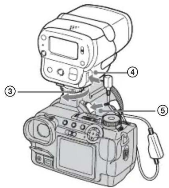
3 When using the digital still camera without the accessory shoe
- Use the supplied connection cord.
- Use the supplied shoe adaptor.

- To use the supplied shoe adaptor, attach the shoe adaptor to the tripod screw hole of the digital still camera.
①Turn in the direction of the arrow to tighten lightly.
- Attach this unit to the shoe adaptor.
② Insert the connection cord into the ACC terminal and the 4 terminal of the digital still camera.
③With the flashing section facing forward, securely attach it to the shoe adaptor.
The accessory shoe can rotate.
④Turn the rotating knob in the direction of the arrow to tighten.
⑤ Attach the connection cord to the connection cord terminal of this unit.
⑥ Fit the shoe adaptor onto the digital still camera and securely tighten ① in the direction of the arrow.
Note
Removing or attaching this unit to a digital still camera while the power is ON, or disconnecting the connection cord while the power is ON can cause the flash to fire erroneously.
14-GB
Using the flash
This digital still camera with an advanced accessory shoe is used here for illustration purposes. Refer to the operating instructions of the digital still camera for each detailed operation.
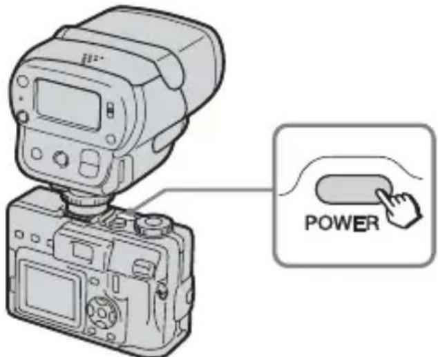
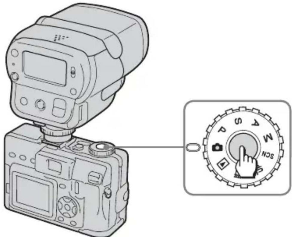
1 Press the POWER switch on the digital still camera to turn "ON".
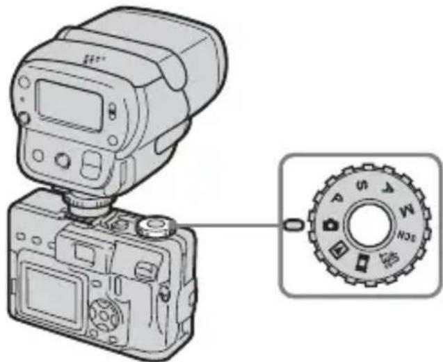
2 Set the mode dial on the digital still camera to “P”, “S”, “A”, “M”, or “SCN”.
Using the flash (continued)
3 Press the control button on the digital still camera to choose "Flash mode".
Each press of the button changes the indication in the following order. No display (AUTO) Forced flash (4) Slow synchro (山 s l ) No flash
- Be sure that "Hot Shoe" is set to [OFF] in the "SET UP" settings.
4 Slide the POWER switch on this unit to "ON".
- The flash starts to be charged, and the READY lamp and CHG lamp on the digital still camera start to flash (orange).
- When the flash is ready to fire, the READY lamp on this unit lights (orange).
When the charging is finished, the CHG lamp on the digital still camera goes out.
- When the batteries are run down, it takes longer to charge this unit.
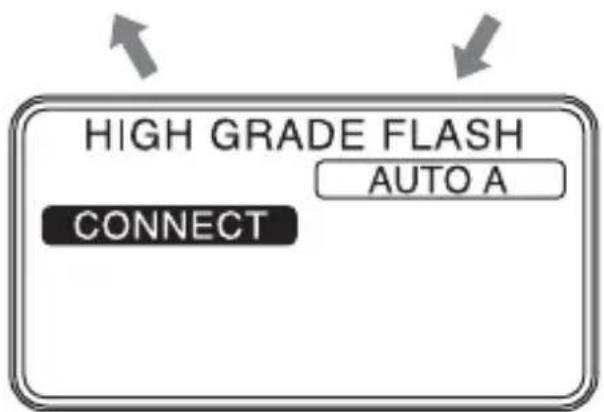
5 The flash mode of the digital still camera compatible with the advanced accessory shoe can be changed in the following order by the mode button on this unit.


This unit performs a pre-flash, the digital still camera calculates the ideal light intensity, and make this unit flash.

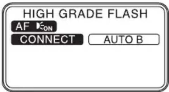
This unit automatically adjusts the light intensity and fires with the ideal light intensity.

The mode in which the user can set the light intensity. The light intensity can be selected using the "light intensity change button" on this unit by the following procedure.
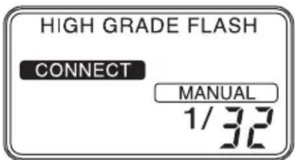
| 1/1 1/2 | 1/4 1/8 1/1 | 6 1/32 | |||
| GN32 (22) | GN22 (16) | GN16 (11) | GN11 (8) | GN8 (6) | GN6 (4) |
- Values within brackets ( ) applies when using the wide panel
To obtain the shooting distance
①Press the mode button and select .MANUAL
② Set the guide number by changing the light intensity.
③ The distance is obtained from the aperture (F-value) of the digital still camera (use in the manual mode).
Distance = Guide Number | Aperture setting (F)
Using the flash (continued)
To obtain the guide number
①Press the mode button and select MANUAL
② Set the aperture on the digital still camera.
③From the formula for distance and aperture obtain the optimum guide number, and select it using the light intensity change button.
Guide Number = Aperture setting (F) · Distance
For Guide Numbers, refer to "Specifications". (p. 30)
Note
Do not close the light exposure meter or the ideal light intensity will not be obtained.
6 AF illuminator
Note
Do not bring the AF illuminator close to person's eyes, and flash.
To select the AF illuminator
If the digital still camera is compatible with an external AF illuminator then AF layed.
The user can select "normal," "strong" and "OFF"

| AF I L L U M I N A T O R | The disital still camera is compatible with the AF illuminator, and allow of using it. → AF ON → AF ON play |
| The disital still camera is compatible with the AF illuminator, but prohibit using it. → No display → AF ON AF ON HIGH Slow flashing Slow flashing | |
| The digital still camera is not compatible with the AF illuminator. → No display → AF ON Fast flashing It turns off after about 2 seconds. |
7 Lightly press the digital still camera shutter button to confirm the image.
Then press the shutter button further.
This unit fires in conjunction with the shutter button.
Meaning of READY lamp states
When it light (orange)
Flash is ready for firing.
When it flashes (orange)
Flash is charging. Firing is not possible.
When it flashes (red)
The batteries are run down.
Replace with new batteries.
(Charging takes longer if the flash has not been used for a long time.)
When the READY does not light
The flashing is prohibited.
(When the digital still camera excepts the shooting mode.)
Bounce flash photography
Enable to shoot in all flash modes.
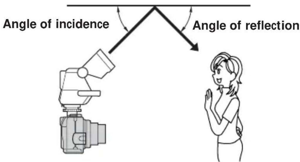
If there is a wall or similar object behind the subject, fire the flashing section pointed at a white ceiling or wall to light the subject using reflected light. As the reflected light spreads in and around the subject over a wide area to light the subject, you can create softer images with fewer shadows on the subject and wall.
Bounce flash on

Bounce flash off
1 Decide on the angle of the flashing section so that the angle of incidence and reflecting angle on the reflecting surface are equal.
The shooting distance means the total distance obtained by adding the distance from the flashing section to the reflecting surface to the distance from the reflecting surface to the subject.
Bounce flash photography (continued)
2 Press the shutter button on the digital still camera.
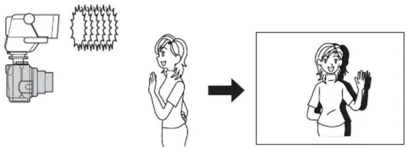
Notes
- A small bounce flash angle causes the light to directly strike the subject together with the reflected light, resulting in uneven illumination.
- Choose a reflecting surface that is near white having high reflectance. Correct colouring cannot be obtained with reflecting surfaces other than white. Also, small reflectance shortens the shooting distance.
Rotating angle of flashing section
The flashing section rotates from 0^ in the down direction up to 90^ in the up direction. Use the flashing section at the fixed positions 45^, 60^, 75^ and 90^ in the up direction.

Notes
- During photography, do not cover the metering sensor on the flash with your fingers, for example. You cannot get the proper light intensity.
When using, isflashing AUTO A You may not be able to get enough light with AUTO A. In that case, use AUTO B or MANUAL - Be careful not to pinch your finger when you change the angle of the flashing section.
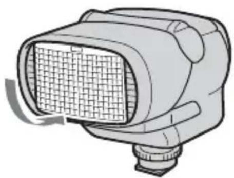
Mounting the wide panel
Use the wide panel when the wide conversion lens is used.
The wide panel widens the illumination angle of the flash.
(The maximum light intensity drops when the wide panel is mounted.)
1 Gently draw out the wide panel.

2 Pull the wide panel down towards the flashing section side, then press the wide panel gently until it clicks.
3 Be sure that indicator is shown on the display panel.
Return the wide panel to its original position
1 Set up the wide panel, then push it straight into the end.
2 Be sure that indicator is disappeared on the display panel.
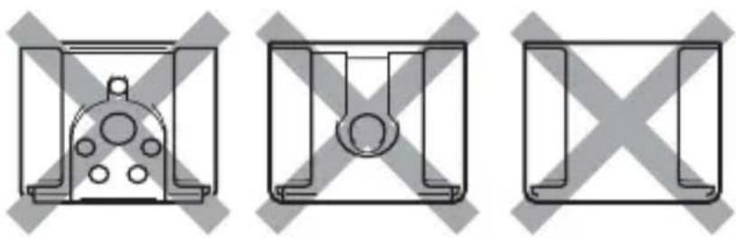
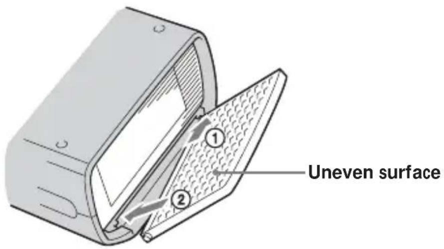
If the wide panel is detached
1 Insert one projection of the wide panel into the hole on the unit facing the uneven surface of the wide panel up.
2 Fit the other projection of the wide panel in the other hole on the unit.
Power save mode
When there is no communication with the digital still camera, this unit will automatically go into power save mode after 1 minute, even when the POWER on this unit is "ON".
The panel display will show POWER SAVE
At that time, the battery cannot be charged and no button input can be performed.
- When this unit is not used for a long time, set the POWER switch to OFF.
Restarting
The unit will restart if you either press the POWER switch again (ON OFF ON) or turn on the power of the digital still camera.
Test flash
Manually operated flash by pressing the test flash button
The procedure varies depending upon the flash mode on this unit.
The test flash can be used in all modes while the READY lamp is lighting.
- Fire the flash with a specific light intensity (Guide Number equivalent to 11), when using, only this unit TO B
- When using MANUAL
Operate the flash with a user-determined light intensity.
Modeling flash
Before taking a photograph it is possible to carry out a pre-flash to confirm shadows of the subject.
After confirming that the READY lamp is on, press the modeling flash button and the flash will light up for about 2 seconds continuously.
Note
Using the modeling flash will allow the direction and area of shadows to be confirmed, however the depth of the shadows will be different from the real photograph. In bright locations or outdoors shadows cannot be confirmed.
Connection cord
When the digital still camera is not compatible with the advanced accessory shoe, connect the connection cord to the digital still camera.

Connection method
Connect ① to the connection cord terminal of this unit.
Connect ② to the ACC terminal of the digital still camera.
③ may be connected to a remote control tripod.
Note
Removing or attaching this unit to a digital still camera while the power is ON, or disconnecting the connection cord while the power is ON can cause the flash to fire erroneously.
Back light
The back light of the LCD can be lit by the user determined operation.
①It can be lit by the user's back light button operation. (color : amber)
(2) The back light turns off at about 10 seconds after it lights.
③ If other button operations are made while lighting, it extends for 10 seconds.
28-GB
Troubleshooting
| Symptom Remedy | |
| The flash does not work | ·Make sure that this unit is properly inserted into the advanced accessory shoe, or the connection cord is properly attached to this unit when using the connection cord. ·Make sure that the POWER switch on this unit is “ON”. ·If the READY lamp is not lit (orange), check the READY lamp again in this instruction manual. ·The flash does not fire if the subject is bright with the digital still camera in the AUTO mode (no display). To forcibly fire the flash when the subject is bright, press the flash button on the digital still camera. ·Make sure that the “Hot Shoe” on the digital still camera is set to [OFF]. (p. 16) ·Depending upon the mode position on the digital still camera, flash is not fired. For details, refer to the operating instructions of your digital still camera again. |
Specifications
Guide Number equivalent to 32
*ISO. 100.m
| Light 35 mm intensity conversion (using the wide panel) | ||
| 1/1 32 22 | ||
| 1/2 22 16 | ||
| 1/4 16 11 | ||
| 1/8 11 8 | ||
| 1/16 8 6 | ||
| 1/32 6 4 | ||
Auto effective distance
*ISO. 100.m
| Auto flash range 35 mm camera conversion |
| 1.4 2.0 m ~ 22.8 m |
| 2.0 1.0 m ~ 16.0 m |
| 2.8 1.0 m ~ 11.4 m |
| 4.0 1.0 m ~ 8.0 m |
| 5.6 1.0 m ~ 5.7 m |
| 8.0 1.0 m ~ 4.0 m |
| 11.0 1.0 m ~ 2.9 m |
| 16.0 1.0 m ~ 2.0 m |
Power requirements 6 V DC, AA alkali battery · 4
Recommended distance 1 to 16m (F2)
Number of flashes 150 times (using a new battery at 20^ )
(Projections are not included in the dimensions)
Mass About 260g (9.2 oz.)
Supplied accessory Shoe adaptor (1)
Connection cord (1)
Pouch (1)
Operating Instructions (1)
Design and specifications are subject to change without notice.
François
AVERTISSEMENT
Installing the batteries 9
Parts identification

Installing the batteries
Utilice quatre pilas alcalinas de时间为 AA.
4 Slide the POWER switch on this unit to "ON".
Printed on 70% or more recycled paper using VOC (Volatile Organic Compound)-free vegetable oil based ink.


- IMPORTANT SAFETY INSTRUCTION
- SAVE THESE INSTRUCTIONS
- Note:
- For the customers in Germany
- Table of contents
- Features
- Caution
- Cleaning
- Parts identification
- Names and functions of the parts
- AF illuminator change button p. 18
- READY lamp p.20
- Test flash button p. 26
- Back light button p.28
- Modeling light button p.27
- POWER switch
- Mode button p.16
- Setting the light intensity p.17
- Display panel
- Installing the batteries
- Notes
- Closing the battery cover
- Mounting the flash
- When using the digital still camera which is compatible with the advanced accessory shoe
- Pin Name
- 12-GB
- When using the digital still camera which is not compatible with the advanced accessory shoe
- Note
- Mounting the flash (continued)
- When using the digital still camera without the accessory shoe
- 14-GB
- Using the flash
- Using the flash (continued)
- Press the control button on the digital still camera to choose "Flash mode".
- Slide the POWER switch on this unit to "ON".
- The flash mode of the digital still camera compatible with the advanced accessory shoe can be changed in the following order by the mode button on this unit.
- To obtain the shooting distance
- To obtain the guide number
- AF illuminator
- To select the AF illuminator
- Lightly press the digital still camera shutter button to confirm the image.
- Meaning of READY lamp states
- Bounce flash photography
- Bounce flash photography (continued)
- Press the shutter button on the digital still camera.
- Rotating angle of flashing section
- Mounting the wide panel
- Return the wide panel to its original position
- If the wide panel is detached
- Power save mode
- Restarting
- Test flash
- Manually operated flash by pressing the test flash button
- Modeling flash
- Connection cord
- Connection method
- Back light
- Troubleshooting
- Specifications
- François
- AVERTISSEMENT
Brand : SONY
Model : HVLF32X
Category : Flash