
HVLF45RM - Flash SONY - Free user manual and instructions
Find the device manual for free HVLF45RM SONY in PDF.
| Product type | Electronic flash for Sony cameras |
| Brand | Sony |
| Model | HVL-F45RM |
| Dimensions (W/H/D) | 69.4 mm × 113.7 mm × 88.3 mm |
| Weight | 317 g (without batteries) |
| Power supply | DC 6 V, 4 AA batteries (alkaline or Ni-MH) |
| Guide number (ISO 100, 105 mm, STD) | 45 (full power, 35 mm format) |
| Flash coverage (zoom) | Auto or manual from 24 mm to 105 mm (with wide-angle adapter: 15 mm) |
| Flash modes | TTL, MANUAL, MULTI, GROUP |
| Wireless functions | Radio (2.4 GHz band, 14 channels, range ~30 m) and optical |
| High-speed sync (HSS) | Yes, up to 1/16000 s |
| LED light | Center intensity ~400 lx at 0.5 m, color temperature ~5500 K |
| AF illuminator | Center zone range 0.5 m to 6 m (F5.6, 50 mm) |
| Tilting reflector | Vertical tilt from -8° to 150°, horizontal rotation from 0° to 180° (in 30° or 45° steps) |
| Number of flashes (alkaline batteries) | Approx. 210 or more (at full power) |
| Recycling time (Ni-MH batteries) | Approx. 0.1 to 2.0 seconds |
| Operating temperature | 0 °C to 40 °C |
| Storage temperature | -20 °C to +60 °C |
| Care and cleaning | Clean with a soft, dry cloth; do not use solvents |
| Safety | Do not expose to rain or moisture; do not touch hot flash tube |
| Spare parts and repairability | Batteries and mini stand included; repair by Sony authorized service |
Frequently Asked Questions - HVLF45RM SONY
User questions about HVLF45RM SONY
0 question about this device. Answer the ones you know or ask your own.
Ask a new question about this device
Download the instructions for your Flash in PDF format for free! Find your manual HVLF45RM - SONY and take your electronic device back in hand. On this page are published all the documents necessary for the use of your device. HVLF45RM by SONY.
USER MANUAL HVLF45RM SONY
Operating Instructions
GB
Mode d'emploi
FR

Update the software of your camera to the latest version before use.
Refer to the dedicated support site for information on camera compatibility.
Before operating the product, please read this manual thoroughly and retain it for future reference.
WARNING
To reduce the risk of fire or electric shock,
1) do not expose the unit to rain or moisture.
2) do not place objects filled with liquids, such as vases, on the apparatus.
Do not expose the batteries to excessive heat such as sunshine, fire or the like.
Do not touch the flashtube during operation, it may become hot when the flash fires.
CAUTION
Replace the battery with the specified type only. Otherwise, burst, fire or injury may result.
Dispose of used batteries according to the instructions.
Notice
If static electricity or electromagnetism causes data transfer to discontinue midway (fail), restart the application or disconnect and connect the communication cable (USB, etc.) again.
This product has been tested and found compliant with the limits set out in the EMC regulation for using connection cables shorter than 3 meters (9.8 feet).
This equipment complies with FCC/IC radiation exposure limits set forth for an uncontrolled environment and meets the FCC radio frequency (RF) Exposure Guidelines and RSS-102 of the IC radio frequency (RF) Exposure rules. This equipment has very low levels of RF energy that are deemed to comply without testing of specific absorption ratio (SAR).
For Customers in the U.S.A.
If you have any questions about this product, you may call:
Sony Customer Information Center
The number below is for the FCC related matters only.
Regulatory Information
Declaration of Conformity
Trade Name: SONY
Model No.: HVL-F45RM
Responsible Party:
Sony Electronics Inc.
Address:
16535 Via Esprillo, San Diego, CA 92127 U.S.A.
Telephone No.:
858-942-2230
This device complies with Part15 of the FCC Rules.
Operation is subject to the following two conditions: (1)
This device may not cause harmful interference, and (2)
this device must accept any interference received, including interference that may cause undesired operation.
This equipment must not be co-located or operated in conjunction with any other antenna or transmitter.
CAUTION
You are cautioned that any changes or modifications not expressly approved in this manual could void your authority to operate this equipment.
Note:
This equipment has been tested and found to comply with the limits for a Class B digital device, pursuant to Part 15 of the FCC Rules.
These limits are designed to provide reasonable protection against harmful interference in a residential installation. This equipment generates, uses, and can radiate radio frequency energy and, if not installed and used in accordance with the instructions, may cause harmful interference to radio communications. However, there is no guarantee that interference will not occur in a particular installation. If this equipment does cause harmful interference to radio or television reception, which can be determined by turning the equipment off and on, the user is encouraged to try to correct the interference by one or more of the following measures:
- Reorient or relocate the receiving antenna.
- Increase the separation between the equipment and receiver.
- Connect the equipment into an outlet on a circuit different from that to which the receiver is connected.
- Consult the dealer or an experienced radio/TV technician for help.
For Customers in Canada
This device complies with Industry Canada's licence-exempt RSSs.
Operation is subject to the following two conditions:
(1) This device may not cause interference; and
(2) This device must accept any interference, including interference that may cause undesired operation of the device.
For Customers in Europe
Manufacturer: Sony Corporation, 1-7-1 Konan Minato-ku Tokyo, 108-0075 Japan
For EU product compliance: Sony Belgium, bijkantoor van Sony Europe Limited, Da Vincilaan 7-D1, 1935 Zaventem, Belgium
CE
Hereby, Sony Corporation, declares that this equipment is in compliance with the essential requirements and other relevant provisions of Directive 1999/5/EC. For details, please access the following URL:
http://www.compliance.sony.de/
Disposal of Old Electrical & Electronic Equipment (Applicable
in the European Union and other European countries with separate collection systems)
This symbol on the product or on its packaging indicates that this product shall not be treated as household waste. Instead it shall be handed over to the applicable collection point for the recycling of electrical and electronic equipment. By ensuring this product is disposed of correctly, you will help prevent potential negative consequences for the environment and human health, which could otherwise be caused by inappropriate waste handling of this product. The recycling of materials will help to conserve natural resources. For more detailed information about recycling of this product, please
contact your local Civic Office, your household waste disposal service or the shop where you purchased the product.
For Customers in Singapore
Complies with IMDA Standards DB00353
For Customers in Malaysia

Table of Contents
Before use....7
Identifying parts 9
Preparations....13
Inserting batteries 13
Attaching/removing the flash unit to/from the camera......14
Turning on the power of the flash unit....15
Pairing with a radio wireless commander/receiver (for radio wireless flash photography)....17
Settings 20
Quick Navi settings....20
MENU settings 22
Photographing....24
Photographing....24
Manual flash photography (MANUAL)....26
High-speed sync photography (HSS)....27
Multiple flash photography (MULTI)....28
Wireless flash photography (with radio or optical communications)......31
Wireless flash photography (with radio wireless communications)....33
Wireless flash photography (with optical wireless communications)......38
Illuminating for video shooting (LED light)....42
Firing a test-flash....43
Selecting the flash coverage (zoom)....44
Bounce flash photography....47
About the AF illuminator 49
Assigning the custom keys 50
Registering/recalling the memory settings....51
Others 52
Notes on use....52
Specifications....54
Before use
This flash unit can be used in combination with Sony Interchangeable Lens Digital Cameras, Sony Interchangeable Lens Digital HD Video Camera Recorders, and Sony Digital Still Cameras that have a conventional Multi Interface Shoe.
Some functions may not work depending on the model of your camera or video camera recorder.
For details on compatible camera models of this flash unit, visit the Sony website in your area, or consult your Sony dealer or local authorized Sony service facility.
See the operating instructions of this unit and refer to the operating instructions of your camera.
Keep the flashtube clean. The soiled flashtube surface may cause heat buildup, resulting in smoke or scorches. To clean the flashtube, wipe it with a soft cloth, etc.
This flash unit is designed with ingress protection in mind, but not tested and found waterproof. Do not use the unit in the rainy weather.
Notes on continuous flashes
The flash unit continues to fire during continuous photographing, multi flash photography, and modeling flashing.
Continuous flashes, as well as reflections of the continuous flashes from walls, may trigger some symptoms such as the seizures in case a person with photosensitivity sees the flashes.
In such a case, immediately stop using the flash unit.
Do not place this flash unit in the following locations
Regardless of whether this flash unit is in use or in storage, do not place it in any of the following locations. Doing so may lead to a malfunction.
- Placing this flash unit in locations subject to direct sunlight such as on dashboards or near a heater may cause this unit to deform or malfunction.
- Locations with excessive vibration
- Locations with strong electromagnetism
- Locations with excessive sand In locations such as the seashore and other sandy areas or where dust clouds occur, protect the unit from sand and dust. This may lead to a malfunction.
Communication distance
The radio wireless communication distance available between this flash unit and the camera is approximately 30 m (98.4 ft.). (Acquired under our measurement conditions.)
- The distance given above applies under conditions where there are no obstacles, shielding, or radio wave interferences.
- The communication distance may be shorter depending on the positioning of the products, the ambient environment, and weather conditions.
Update the software of your camera to the latest version before use.
Refer to the dedicated support site for information on camera compatibility.

http://www.sony.net/flash/f45rm/
Identifying parts
GB
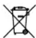
① Built-in wide panel (44)
② Flashtube
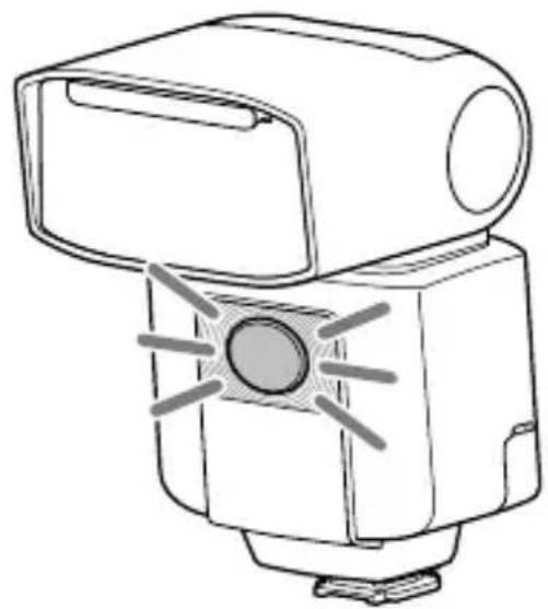
③ LED light unit (42) / AF illuminator (49)
4 Wireless control signal receiver (for optical wireless communications)
5 Multi Interface foot (14)
6 Multi/Micro USB Terminal
7 Bounce sheet (48)

8 Bounce indicator (upper/lower angle) (47)
9 LINK lamp (35)
10 LCD panel (11)
11 Control panel (10)
12 Lock lever (14)
13 Release button (14)
14 Battery chamber door (13)
15 Mini-stand (32)
* Tripod attachment hole
The number in the parentheses indicates the page number where you can find the description.
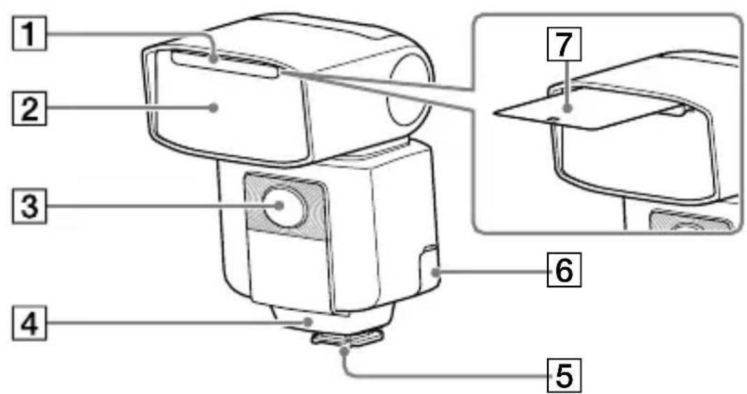
Operation console
① Fn button (20)
2 TEST button (43)
3 Control wheel
Use the wheel to move the focus or change the setting item value on the Quick Navi screen or the MENU settings screen.
4 Direction buttons
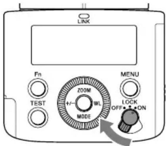
5 Power switch (15)
Selecting "LOCK" disables the control wheel and the buttons on the flash unit and you can prevent unintentional operations.
6 MENU button (22)
7 Center button
The number in the parentheses indicates the page number where you can find the description.
About the LCD backlight
The LCD backlight turns on and stays lit for about 8 seconds every time you press one of the buttons or use the control wheel on the flash unit.
- While the LCD backlight is lit, you can press one of the buttons or use the control wheel on the unit to keep it lit longer.
- To turn off the LCD backlight, press the MENU button and select [BACKLIGHT], and then [OFF].
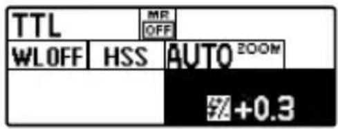
On-screen indicators
The following screen images are given as examples and may look different from what you actually see on the LCD panel.
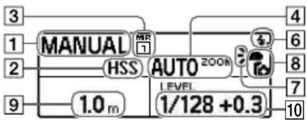
TTL flash mode

MANUAL flash mode
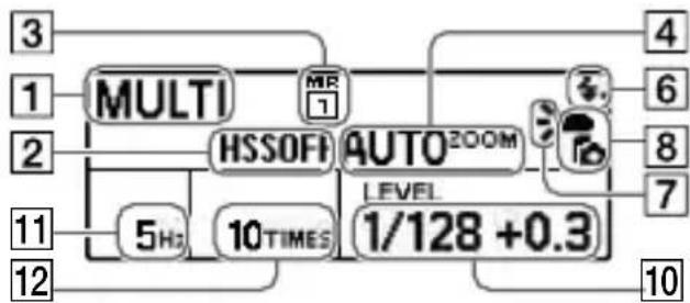
MULTI flash mode
flowchart
graph TD
    A["3"] --> B["MULTI"]
    C["1"] --> B
    D["2"] --> E["HSSOFF"]
    F["11"] --> G["5Hz"]
    H["12"] --> I["10TIMES"]
    J["4"] --> K["AUTO2OOM"]
    L["6"] --> K
    M["8"] --> K
    N["7"] --> K
    O["10"] --> P["1/128 +0.3"]
1 Flash mode
2 High-speed sync
3 Memory Recall
4 Flash coverage (zoom)
5 Bounce flash
6 Ready to fire
7 Flash distribution setting
8 Attached to camera
9 Flash range
10 Power level
11 Frequency in multiple flash
12 Repetition in multiple flash
13 Wireless channel
14 Wireless mode
15 Lighting ratio control setting
16 Flash compensation
17 Lighting ratio
18 Receiver remote setting
19 Wireless group setting
20 Flash distribution setting/Commander/Control unit flash setting
21 Low-battery indicator
22 Overheat indicator
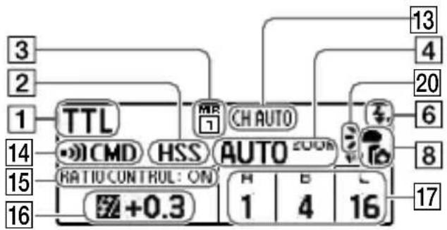
Wireless commander mode (radio control)
Wireless receiver mode (radio control)

Wireless controller mode (optical wireless communications)

Wireless remote mode (optical wireless communications)

1 Flash mode
② High-speed sync
3 Memory Recall
4 Flash coverage (zoom)
5 Bounce flash
6 Ready to fire
7 Flash distribution setting
8 Attached to camera
9 Flash range
10 Power level
11 Frequency in multiple flash
12 Repetition in multiple flash
13 Wireless channel
14 Wireless mode
15 Lighting ratio control setting
16 Flash compensation
17 Lighting ratio
18 Receiver remote setting
19 Wireless group setting
20 Flash distribution setting/Commander/Control unit flash setting
21 Low-battery indicator
22 Overheat indicator
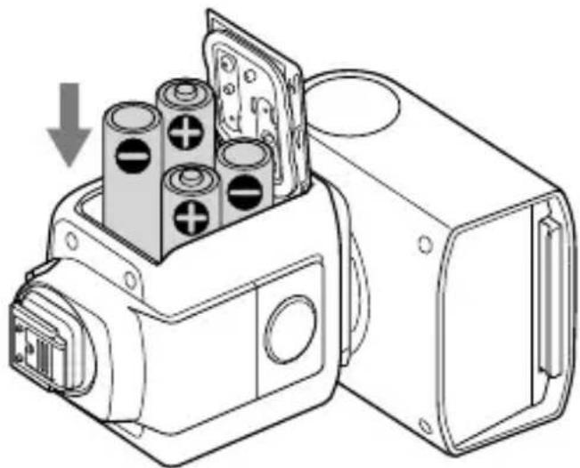
Inserting batteries
The flash unit can accommodate either set of the following:
• Four AA-size alkaline batteries
- Four AA-size rechargeable nickel-metal hydride (Ni-MH) batteries. Before you use the rechargeable nickel-metal hydride batteries, be sure to fully charge the batteries with the specified battery charger. No batteries are supplied with the flash unit.
GB
1 Push and slide the battery chamber door in the direction of the arrow shown below.
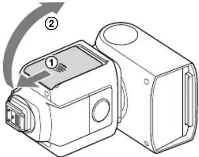
2 Insert the batteries into the battery chamber as illustrated (☐ ☐)
(indicate the direction of the batteries.)
natural_image
Technical line drawing of a mechanical device with cylindrical components and a housing (no text or symbols)3 Close the battery chamber door.
Slide the door in the reverse direction of the arrow in step 1.
Attaching/removing the flash unit to/from the camera
To attach the flash unit to the camera
1 Turn off the power of the flash unit.
If your camera is equipped with a built-in flash, make sure that the camera flash is not released.
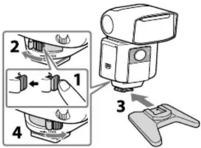
2 Remove the terminal protection cap from the Multi Interface foot on the flash unit; and the shoe cap from the Multi Interface shoe on the camera.
3 Press and hold the release button and rotate the lock lever away from "LOCK."

4 Insert the Multi Interface foot of the flash unit into the Multi Interface shoe on the camera and push in the foot all the way.
5 Rotate the lock lever toward "LOCK" to secure the flash unit on the camera.
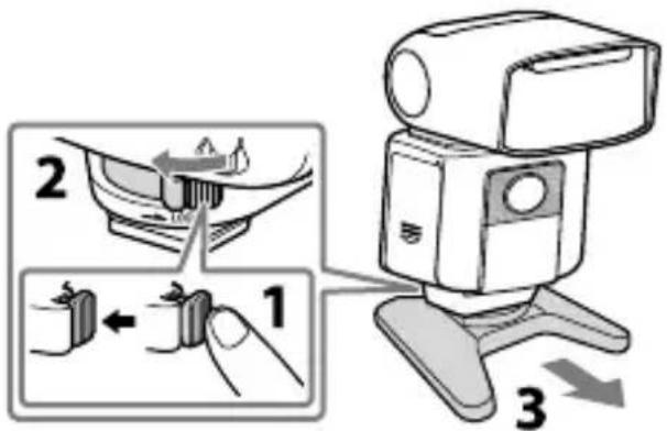
To remove the flash unit from the camera
Turn off the power of the flash unit first. Press and hold the release button, rotate the lock lever away from "LOCK," and then slide the unit out of the Multi Interface shoe.
Notes
When you do not intend to use the flash unit, be sure to attach the terminal protection cap back to the Multi Interface foot.
Turning on the power of the flash unit
Turn on the power switch.
When the flash unit is powered, on-screen indicators are displayed on the LCD panel.
Power-saving mode
- If the flash unit is left unused for 3 minutes while it is used alone or connected to the camera in a power-saving state, the LCD panel will automatically turn off to conserve the battery power.
- During wireless flash photography with the flash unit used as an off-camera flash (page 31), the flash unit goes into power-saving mode in 60 minutes.
- Turning off the power switch on the connected camera* automatically places the flash unit in power-saving mode. * Except for DSLR-A100
- You can press the MENU button and select [POWER SAVE] to specify the power-saving timer, or select [WL POWER SAVE] to specify the power-saving timer for wireless flash photography.
Checking the remaining battery power
When the batteries are running out of power, the low-battery indicator is displayed on the LCD panel as a warning.
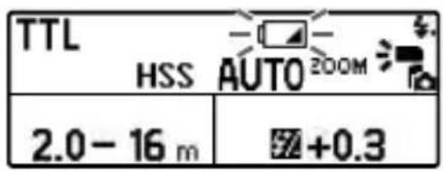
When is blinking:
It is recommended that you replace the batteries. The flash unit, however, is still capable of firing in this state.
When nothing but is on the LCD panel:
The flash unit is not capable of firing. Replace the batteries.
Notes on continuous flashes
If you use the flash unit continuously for a short period of time, its built-in safety circuit may be triggered to reduce the flash counts by increasing the flash frequency.
Also, if the temperature inside the flash unit rises further, (overheat indicator) will light on the LCD panel to indicate that flash firing is disabled for a while. In such a case, turn off the power switch on the flash unit and leave the unit unused for about 10 minutes to allow it to cool down.
Continuous flashes heat up the batteries inside the flash unit. Take extra care if you need to remove the batteries.
Pairing with a radio wireless commander/receiver (for radio wireless flash photography)
To perform radio wireless flash photography with this flash unit, you need another flash unit that supports radio wireless communications or a radio wireless commander/receiver (not supplied) in addition to this flash unit and must pair them both together.
This section describes how to pair two HVL-F45RM (this flash unit) units.
For pairing the flash unit with a radio wireless commander/receiver (not supplied), refer to the operating instructions supplied with the device.
Tips
- You need to bring both devices within 1 m from each other for pairing.
- You can pair the flash unit with up to 15 radio wireless devices.
1 Turn on the power of this flash unit and the other device.
GB
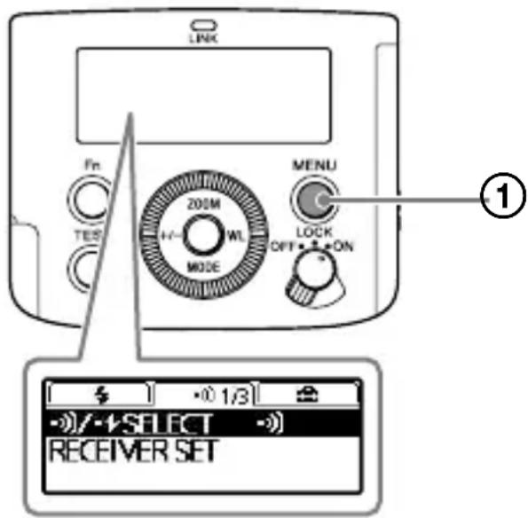
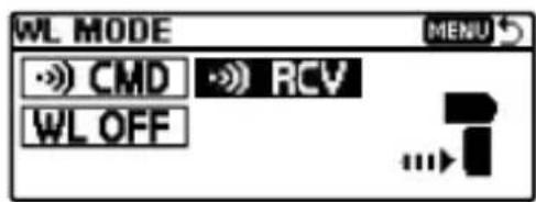
2 Press the WL button (①) to display the screen for setting the wireless mode, and then specify one flash unit as the commander unit and the other as the receiver unit.

• To specify a flash unit as the commander unit, select [CMD].

• To specify a flash unit as the receiver unit, select [RCV].

Notes
- The above instructions are given based on the assumption that this flash unit uses default radio wireless communications. This flash unit is capable of using 2 types of wireless communications for wireless flash photography: radio and optical wireless communications. For setting the unit to use optical wireless communications, see page 31.
- You can press the MENU button and select [PAIRED DEVICE] to see the flash unit(s) paired as the receiver unit(s) or delete the paired receiver unit(s).
- When you have changed the setting of the commander unit and specified it as a receiver unit, or vice versa, be sure to reestablish paring among the units.
3 On this flash unit and the other flash unit, press the MENU button (②) and select [PAIRING].
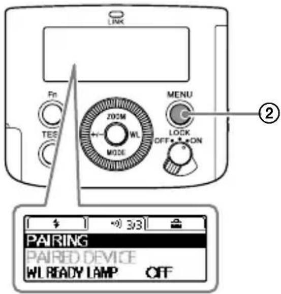
- On the commander unit, the following screen is displayed.

- On the receiver unit, the following screen is displayed.

4 Select [OK] to establish pairing.
- On the commander unit, the following screen is displayed.

Pairing is established. On the commander unit, you can continue pairing with other receiver units. Every time pairing is established with a receiver unit, the number of paired devices (③) increases.
- On the receiver unit, the following screen is displayed.
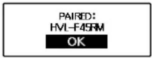
Pairing is established.
When pairing is established, the LINK lamp turns from red to green in color.
To establish a pairing with 2 or more devices
Set each device to be paired with this flash unit as the receiver unit and repeat steps 3 and 4.
When you are finished with pairing with all receiver units, select [EXIT] on the commander unit, and then [OK] on the following screen.

Quick Navi settings
You can press the Fn button on the flash unit to change the settings for photography, such as the selected flash mode, in accordance with the on-screen indications.
Select the setting item of choice and rotate the control wheel to change the setting option.
1 Press the Fn button (①).

2 Select the setting item of your choice with the direction buttons.
Pressing the center button following the above operation displays the specific screen for setting the selected item.
3 Rotate the control wheel to change the setting option.

4 Press the Fn button.
| Setting items Descriptions Setting options | ||
| TTL Flash mode setting | TTL(*)/MANUAL/MULTI/flash off/GROUP | |
| MROFF | Memory Recall OFF(*)/MR1/MR2 | |
| WLOFF | Wireless mode setting | WF OFF(*)/CMD/RCV (radio control)WF OFF(*)/CTRL/RMT (optical control) |
| HSS High-speed sync setting ON(*)/OFF | ||
| AUTO200M | Flash coverage (zoom) setting | AUTO(*)/24-105 |
| ±0.0 | Flash compensation setting | -3.0 - +3.0 |
| 1/1 Power level setting 1/1 - 1/128, CMD LINK | ||
| 5Hz Frequency in multiple flash 1 - 100 | ||
| 10TIMES Repetition in multiple flash 2 - 100, -- | ||
| >7 | CMD flash setting (radio control)CTRL flash setting (optical control) | ON(*)/OFF |
| RATIO CONTROL: OFF | Lighting ratio setting ON/OFF(*) | |
| A B C | Power level ratio setting | OFF/1(*) - 16 |
| RCV REMOTE: OFF | Receiver remote setting | ON/OFF(*) |
| GROUP: A | Wireless group setting | OFF/ A(*)/B/C/D/E (radio control)RMT(*)/RMT2 (optical control) |
* Factory default setting
The items and options available for setting vary depending on the flash mode.
MENU settings
You can press the MENU button on the flash unit to change the MENU settings.
Move the focus to the setting item of your choice with the direction buttons, and then press the center button to select the item.
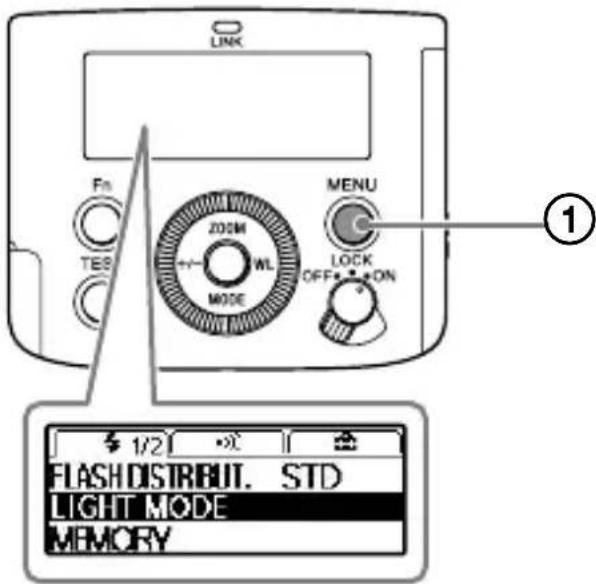
1 Press the MENU button (①).
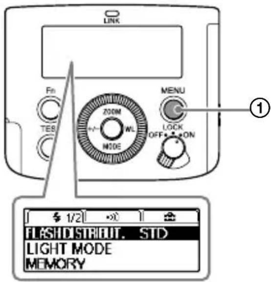
2 Move the focus to the setting item of your choice with the direction buttons, and then press the center button.
3 Change the setting option with the direction buttons and press the center button.
| Groups | Setting items Descriptions Setting options | ||
| # | FLASHDISTRIBUT. | Flash distribution setting | STD(*)/CENTER/EVEN |
| LIGHT MODE LED light ON/OFF setting ON/OFF | |||
| MEMORY Memory settings MR1/MR2 | |||
| AF LED LEVEL AF illuminator level setting HIGH(*)/LOW | |||
| TEST Test-flash setting | GROUP/1TIME(*)/3TIMES/4SEC | ||
| LEVEL STEP Power level setting steps 0.3EV(*)/0.5EV | |||
| CUSTOM KEY Custom key settings - | |||
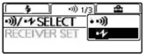
| # | -#)/-#ELECT | Wireless control type setting | -#)(*)/-# |
| RECEIVER SET Receiver settings - | |||
| CH SET | Radio controlled wireless CH setting | AUTO(*)/CH1-CH14 | |
| -#CH SET | Optical controlled wireless CH setting | CH1(*)-CH4 | |
| PAIRING | Pairing setting | - | |
| PAIRED DEVICE | Paired device display | - | |
| WL READY LAMP | Wireless flash ready lamp setting ON/OFF(*) | ||
| # | BACKLIGHT LCD backlight setting AUTO(*)/ON/OFF | ||
| m/ft | Flash range unit setting | m(*)/ft | |
| POWER SAVE | Power-saving timer setting | 30SEC/3MIN(*)/30MIN/OFF | |
| WL POWER SAVE | Wireless flash power-saving timer setting | 60MIN(*)/240MIN/OFF | |
| VERSION | Version display for this product's /RCV software | - | |
| RESET | Reset setting for Quick Navi screen - | ||
| INITIALIZE | Restoring the default settings at shipment | - | |
* Factory default setting
Photographing
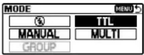
Selecting the flash mode
You can press the MODE button (①) and rotate the control wheel to select the flash mode of the flash unit.
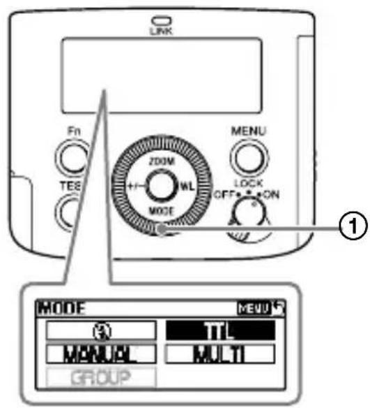
- TTL* flash mode
The flash unit measures the amount of light coming through the lens and automatically adjusts the flash power level.
* TTL stands for Through The Lens. - MANUAL flash mode (page 26) You need to manually adjust the flash power level for keeping it consistent.
-
MULTI flash mode (page 28) You can specify the number of repetition in multiple flash and the frequency in multiple flash.
-
Group flash mode (page 36) You can select this flash mode for radio wireless flash photography.
- Flash off mode Flash firing is disabled.
TTL flash photography
1 Select the flash mode.
Select TTL flash mode.
2 Press the shutter button to take a photo.
Make sure that the flash unit is ready to fire before you press the shutter button. The orange-lit TEST button indicates that the flash unit is ready to fire.
• Take photos within the indicated flash range.
This flash unit is capable of indicating distances within the range from 0.7 m to 28 m. If the distance is beyond this range, + or → next to the flash range indicator will light.
- You can press the +/- button to change the flash compensation (adjust the flash power level) on the screen for setting the flash compensation.
- To use fill-flash or auto-flash mode of the camera, you need to select the mode on the camera.
- Before photographing with the flash unit using the self-timer of the camera, make sure that the TEST button is lit.
- If flash compensation is made both on the flash unit and the camera, both compensation values are added up for flash firing. On the LCD panel of the flash unit, however, only the compensation value specified on the unit is displayed.
Auto WB adjustment with color temperature information
White balance is automatically adjusted on the camera (except for DSLR-A100) based on the color temperature information at the time of flash firing.
- This function works when the flash unit is attached to the camera and placed in TTL flash mode.
- This function works when [Auto] or [Flash] is specified for the white balance on the camera.
GB
TTL\*-flash mode
Manual-flash mode provides a fixed flash power irrespective of the brightness of the subject and the camera setting. TTL-flash mode measures the light from the subject that is reflected through the lens. TTL metering also has a P-TTL metering function, which adds a pre-flash to TTL metering, and an ADI metering function, which adds distance data to the P-TTL metering.
* TTL stands for Through The Lens.
- ADI metering is possible in combination with a lens with a built-in distance encoder. Before using the ADI metering function, check whether your lens has a built-in distance encoder by referring to the specifications in the operating instructions supplied with your lens.
Manual flash photography (MANUAL)
Manual flash mode keeps the flash power level consistent regardless of the brightness of the subject or the settings of the camera.
1 Select M (Manual) shooting mode on the camera.
2 Press the MODE button (①) to display the screen for setting the flash mode, and then select [MANUAL].
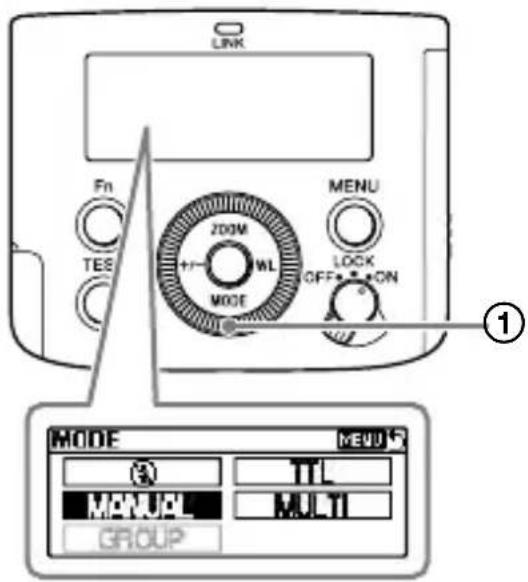
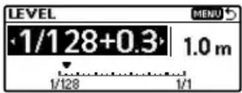
3 Press the +/- button and specify the flash power level of your choice on the screen for setting the power level.
- You can specify the flash power level in the range from 1/1 (brightest) to 1/128 (darkest).
- Increasing the flash power by one level (e.g. 1/1 → 1/2) is equivalent to increasing the aperture by one level (e.g. F4 → 5.6).
4 Press the shutter button to take a photo.
Tips
- You can press the shutter button halfway down to display the distance for the proper exposure on the LCD panel.
- You can press the MENU button and select [LEVEL STEP] to change the power level setting step ([0.3EV] or [0.5EV]).
High-speed sync photography (HSS)

natural_image
Black-and-white close-up of white flowers with blurred foliage background (no text or symbols)
natural_image
Black-and-white photo of white flowers with green foliage in the background (no text or symbols visible)High-speed sync photography Normal flash photography
High-speed sync photography eliminates the flash sync speed restrictions and enables the flash unit to be used through the entire shutter speed range of the camera. An increase in the selectable aperture range allows flash photography with a wide aperture, leaving the background out of focus and accentuating the front subject. When photographing a scene, where the background is very bright and the photograph is likely to be over-exposed, at a wide f-stop in A or M shooting mode of the camera, you can still adjust the exposure to the proper level by using the high-speed shutter.
To turn off the HSS function, follow the instructions for Quick Navi settings (page 20) and change the setting option for [HSS] to [OFF].
Flash sync speed
Flash photography is generally associated with the maximum shutter speed referred to as the flash sync speed. This restriction does not apply to cameras designed for high-speed sync (HSS) photography, since they allow flash photography at the maximum shutter speed of the camera.
Notes
If you set the shutter speed of the camera faster than 1/4000 and take a photo, bright and dark streaks may appear on the photo.
It is recommended that you set the flash power level to at least MANUAL 1/2 for photography.
Multiple flash photography (MULTI)
This flash unit is capable of firing multiple times while the camera shutter is open (multiple flash photography). Multiple flash photography allows you to capture a series of movements of the subject in a single photo. For multiple flash photography, you need to place the camera in M shooting mode. Otherwise, you may not obtain the proper exposure.

natural_image
Black and white abstract pattern with folded paper-like shapes on a dark textured background (no text or symbols)1 Press the MODE button (①) to display the screen for setting the flash mode, and then select [MULTI].

2 Press the Fn button, select the following items with the direction buttons, and specify the setting option with the control wheel.
① [Hz]: Frequency in multiple flash
② [TIMES]: Repetition in multiple flash
③ [LEVEL]: Power level setting

- Setting options
① [Hz]: 1 Hz - 100 Hz
② [TIMES]: 2 - 100, --
③ [LEVEL]: 1/8 - 1/128
When [TIMES] is set to [--], the flash unit continuously fires as many times as possible with the specified frequency in multiple flash.
3 Set the shutter speed and the aperture on the camera.
The shutter speed should be at least equal to the number specified for repetition in multiple flash (TIMES) divided by the specified frequency in multiple flash (Hz).
For example, if the number for repetition in multiple flash is specified to "10" and the frequency in multiple flash to "5 Hz", set the shutter speed of the camera to at least 2 seconds.
4 Make sure that the flash unit is ready to fire, and then press the shutter button to take a photo.
To avoid blurring of images due to hand movement, it is recommended that you use a tripod for multiple flash photography.
GB
Maximum number for repetition in multiple flash
Due to the limited battery capacity, the maximum numbers that you can specify for repetition in multiple flash are shown in the following tables as guidelines.
When using the alkaline batteries
| Power levels | Flash frequencies (Hz) | ||||||||||||||||||
| 100 | 90 | 80 | 70 | 60 | 50 | 40 | 30 | 20 | 10 | 9 | 8 | 7 | 6 | 5 | 4 | 3 | 2 | 1 | |
| 1/8 | 5 | 5 | 5 | 5 | 5 | 5 | 6 | 6 | 6 | 7 | 7 | 8 | 9 | 10 | 100* 100* | ||||
| 1/16 | 8 | 8 | 9 | 9 | 9 | 10 | 10 | 10 | 15 | 15 | 20 | 20 | 30 | 45 | 65 | 100* 100* 100* | |||
| 1/32 | 15 | 15 | 15 | 15 | 17 | 17 | 18 | 18 | 20 | 40 | 50 | 65 | 80 | 100* 100* 100* 100* 100* 100* 100* 100* 100* 100* 100* 100* 100* 100* 100* 100* 100* 100* 100* 100* 100* | |||||
| 1/64 | 30 | 30 | 32 | 32 | 35 | 37 | 40 | 45 | 75 | 100* 100* 100* 100* 100* 100* 100* 100* 100* 100* 100* 100* 100* 100* 100* 100* 100* 100* 100* 20 | |||||||||
| 1/128 | 60 | 60 | 65 | 65 | 70 | 100* 100* 100* 100* 100* 100* 100* 100* 100* 100* 100* 100* 100* 100* 100* 100* 100* 100* 100* | |||||||||||||
"100*" indicates 100 or greater.
When using the nickel-hydride batteries (2100 mAh)
| Power levels | Flash frequencies (Hz) | |||||||||||||||||||
| 100 | 90 | 80 | 70 | 60 | 50 | 40 | 30 | 20 | 10 | 9 | 8 | 7 | 6 | 5 | 4 | 3 | 2 | 1 | ||
| 1/8 | 5 | 5 | 5 | 5 | 5 | 6 | 6 | 7 | 7 | 8 | 8 | 10 | 10 | 25 | 100* | 100* | 100* | |||
| 1/16 | 8 | 8 | 9 | 9 | 9 | 10 | 10 | 10 | 15 | 20 | 30 | 60 | 75 | 100* | 100* | 100* | 100* | |||
| 1/32 | 17 | 17 | 18 | 18 | 18 | 19 | 20 | 20 | 40 | 80 | 100* | 100* | 100* | 100* | 100* | 100* | 100* | |||
| 1/64 | 32 | 33 | 35 | 36 | 40 | 45 | 55 | 95 | 100* | 100* | 100* | 100* | 100* | 100* | 100* | 100* | ||||
| 1/128 | 63 | 65 | 70 | 100* | 100* | 100* | 100* | 100* | 100* | 100* | 100* | 100* | 100* | 100* | 100* | 100* | 100* | 100* | ||
"100*" indicates 100 or greater.
Notes
The maximum number that you can specify for repetition in multiple flash varies depending on the type and condition of the batteries.
Wireless flash photography (with radio or optical communications)
This flash unit supports 2 types of wireless communications for wireless flash photography: radio and optical wireless communications.
Radio wireless flash photography
Wireless flash photography is available using the radio communication method. This helps you photograph with the flash unit in an environment with many obstacles.
For radio wireless flash photography, you need another flash unit or a wireless commander/receiver (not supplied) that supports radio wireless communications in addition to this flash unit.
Notes
For radio wireless flash photography, you need the camera that supports radio wireless communications. Refer to the operating instructions supplied with the camera.
Optical wireless flash photography
Wireless flash photography is available using the optical communication method. This helps you photograph with the flash unit in an environment where radio communications are not available.
For optical wireless flash
photography, you need another flash unit that supports optical wireless communications in addition to this flash unit.
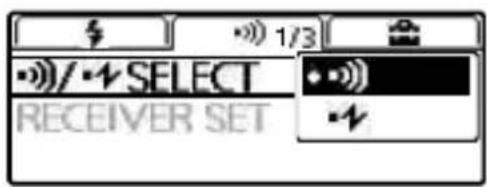
To switch the wireless communication method
GB
1 Press the MENU button (①) and select [•/• SELECT] with the direction buttons.
2 Select the wireless communication method of your choice.
-»): Radio wireless communications with the flash unit
- Optical wireless communications with the flash unit
Attaching and removing the mini-stand
When you have removed the flash unit from the camera to place and use it alone for wireless flash photography, attach the supplied mini-stand to the unit.
To attach the mini-stand
To remove the mini-stand
For instructions on using the release button and the lock lever, see page 14.
Tips
You can screw the mini-stand to a tripod through the screw hole on the mini-stand.
Use a tripod with the screw that is shorter than 5.5 mm in length. To a tripod with the longer screw, you cannot secure the mini-stand firmly with the screw, resulting in possible damage to the mini-stand.
Wireless flash photography (with radio wireless communications)
Radio wireless flash photography
This flash unit supports radio wireless communications for flash photography.
Specify [CMD] for the commander unit attached to the camera; and [RCV] for the receiver unit (off-camera flash) of which flash operation is wirelessly triggered.
Tips
To perform radio wireless flash photography, you need to establish paring between the commander unit and the receiver unit(s) in advance (page 17).
1 Press the WL button (①) on this flash unit and select [CMD] for the commander unit; and [RCV] for the receiver unit.

- To specify the flash unit as the commander unit, select [CMD].
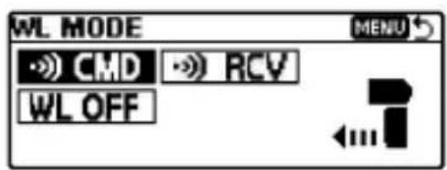


- To specify the flash unit as the receiver unit, select [RCV].


The radio wireless communication distance available between the commander unit and the receiver unit is approximately 30 m (98.4 ft.). (Acquired under our measurement conditions.)
Wireless flash photography (with the receiver unit)
You can specify another flash unit attached to the camera or the radio wireless commander as the commander unit, and then use the commander unit to trigger the flash operation of this flash unit placed away from the camera.
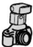
①


②
① Commander unit (CMD)
② HVL-F45RM
As the commander unit, you can use this flash unit or a radio wireless commander.
1 Select wireless (WL) flash mode on the camera.
For selecting the flash mode on the camera, refer to the operating instructions supplied with the camera.
2 Press the WL button on this flash unit and select [RCV].
3 Press the Fn button and specify the wireless group for this flash unit.
4 Attach the mini-stand to this flash unit (page 32).
5 Attach another flash unit specified as [CMD] (commander unit) to the camera.
Make sure that [CMD] is displayed on the LCD panel of the commander unit.
6 Place the camera and this flash unit.
7 Make sure that the flash unit on the camera (commander unit) and this flash unit are wirelessly connected and ready to fire.
Wirelessly connected: The LINK lamp is lit in green. Ready to fire: The TEST button on the back of the unit is lit in orange. In addition, while [ON] is selected for [WL READY LAMP] on the MENU settings screen, the AF illuminator on the front of the receiver unit blinks.
8 Press the shutter button to take a photo.
To fire a test-flash, press the TEST button on the commander unit.
Tips
- On the receiver units, the flash mode of the commander unit is applied.
- During manual flash photography, you can press the Fn button and specify [CMD LINK] for the power level setting to allow adjustment on the commander unit.
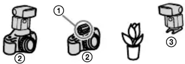
Multiple wireless flash photography with lighting ratio control
You can perform wireless flash photography while controlling the lighting ratio among a maximum of 3 groups including the commander unit and 2 groups of off-camera flashes. Commander unit: HVL-F45RM (this flash unit) or a radio wireless commander Receiver unit (off-camera flash): HVL-F45RM (this flash unit) or a wireless receiver
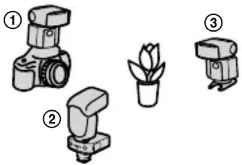
natural_image
Illustration of three camera models and a potted plant, no text or symbols present① Commander unit (CMD)
② Wireless receiver
③ Receiver unit (RCV)
- Press the Fn button on the commander unit and select [ON] for [RATIO CONTROL: OFF].
- The commander unit fires as the flash unit in the A group.
- If you do not want the commander unit to fire, press the Fn button and specify [OFF] for the ➤ CMD flash setting.
To set the lighting ratio of the commander unit
Press the Fn button on this flash unit and specify the power level ratio setting for the A, B, and C groups.
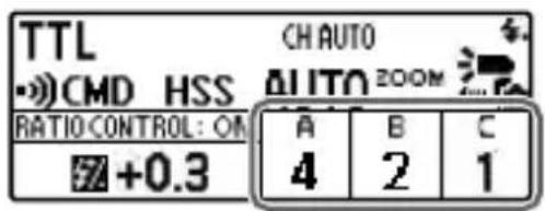
Example: When the flash power level ratio [4:2:1] is displayed on the LCD panel, the flash unit in each group fires with a fraction of the total flash power: 4/7, 2/7, and 1/7, respectively.
Multiple wireless flash photography (group flash photography)
You can perform wireless flash photography among a maximum of 5 groups including the commander unit and 4 groups of off-camera flashes. To perform group flash photography, specify [GROUP] for the flash mode setting.
Commander unit: HVL-F45RM (this flash unit) or a radio wireless commander Receiver unit (off-camera flash): HVL-F45RM (this flash unit) or a wireless receiver
You can specify [TTL], [MANUAL], or [OFF] for the flash mode of the A, B, and C groups. For the D and E groups, on the other hand, you can specify either [MANUAL] or [OFF].
The flash units in the group with the flash mode specified as [OFF] do not fire.
To set up for group flash photography
Press the Fn button on this flash unit and specify the flash mode setting, the flash compensation setting, and the power level setting for the A, B, C, D, and E groups on the screen for setting the group flash mode.
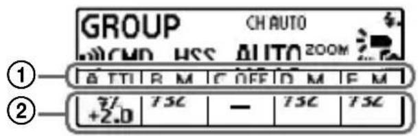
① Flash mode setting
② Flash compensation/power level setting
Changing the settings of individual receiver units (RECEIVER SET)
You can press the MENU button on the commander unit and specify [RECEIVER SET] to change the wireless group setting and the flash coverage (zoom) setting of individual receiver units paired with the commander unit.
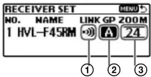
① Wireless connection status
② Wireless group setting
You can select [A], [B], [C], [D], [E], or [OFF].
③ Zoom setting
You can change the zoom setting for the receiver unit.
Notes
To enable the commander unit to change the settings of individual receiver units, you need to press the Fn button on each receiver unit and select [ON] for [RCV REMOTE].
Notes on wireless flash photography with radio wireless communications
- During photography with off-camera flashes, P-TTL flash metering is automatically used instead of ADI metering.
- You can concurrently use up to 15 receiver units (off-camera flashes).
- On the commander unit, press the MENU button, select [CH SET], and then specify the channel to be used for radio wireless communications. While [AUTO] is selected for [CH SET], a channel appropriate for the radio conditions at the time that you turn on the flash unit is used.
Wireless flash photography (with optical wireless communications)
Optical wireless flash photography
This flash unit supports optical wireless communications for flash photography. Specify [CTRL] for the flash unit attached to the camera as the controller unit; and [RMT] for the off-camera flash of which flash operation is wirelessly triggered as the remote unit.
1 Press the WL button (①) and select [CTRL] for the controller unit; and [RMT] for the remote unit.

- To specify the flash unit as the controller unit, select [CTRL].
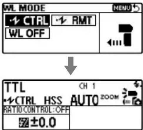
• To specify the flash unit as the remote unit, select [RMT].

Place the controller and remote units within a 5 m radius of the subject.
Wireless flash photography (with the remote unit)
You can specify another flash unit attached to the camera or the built-in flash of the camera as the controller unit, and then use the controller unit to trigger the flash operation of this flash unit placed away from the camera.
① Built-in flash
② Controller unit (CTRL)
③ HVL-F45RM
As the controller unit, you can use the built-in flash of an A-mount camera or another flash unit model (HVL-F20M, HVL-F32M, HVL-F43M, HVL-F60M, etc.) available for a separate purchase.
1 Attach this flash unit to the camera and turn on the power of both devices.
2 Select wireless (WL) flash mode on the camera.
For selecting the flash mode on the camera, refer to the operating instructions supplied with the camera.
GB
3 Remove the flash unit from the camera (page 14) and attach the mini-stand to the unit (page 32).
4 Release the built-in flash of the camera or attach another flash unit to the camera.
- Make sure that [RMT] is displayed on the LCD panel of this flash unit. If [CTRL] is displayed, press the WL button and change the setting option to [RMT].
- Make sure that the flash unit attached to the camera is specified as the controller unit. For details, refer to the operating instructions supplied with the attached flash unit.
5 Place the camera and this flash unit.
6 Make sure that the flash on the camera (controller unit) and this flash unit are ready to fire.
When this flash unit is ready to fire, the TEST button on the back of the unit lights in orange. In addition, while [ON] is selected for [WL READY LAMP] on the MENU settings screen, the AF illuminator on the front of the receiver unit blinks.
7 Press the shutter button to take a photo.
- For firing a test-flash with the camera flash, refer to the operating instructions supplied with the camera.
- If this flash unit does not fire, change the locations of the camera, this flash unit, and the subject; or point the wireless control signal receiver of this flash unit toward the camera.
Multiple wireless flash photography with lighting ratio control
You can perform wireless flash photography while controlling the lighting ratio among a maximum of 3 groups including the controller unit and 2 groups of off-camera flashes.
Controller unit: HVL-F45RM (this flash unit)
Remote unit (off-camera flash): HVL-F45RM (this flash unit) or another flash unit model that supports optical wireless communications
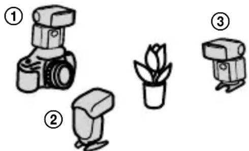
natural_image
Illustration of three types of photography cameras and a potted plant, labeled ①, ②, and ③ (no text or symbols on devices)① Controller unit (CTRL)
② Remote unit (RMT)
③ Remote unit (RMT2)
- Press the Fn button on the controller unit and select [ON] for [RATIO CONTROL: OFF].
- You can classify off-camera flashes (remote units) into 2 groups (RMT and RMT2). Press the Fn button on the remote unit and change its wireless group setting.
- If you do not want the commander unit to fire, press the Fn button and specify [OFF] for the ⚠ CMD flash setting.
To set the lighting ratio of the controller unit
Press the Fn button on this flash unit and specify the power level ratio setting for the CTRL, RMT, and RMT2 units.
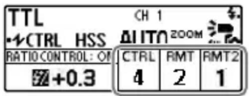
Example: When the flash power level ratio [4:2:1] is displayed on the LCD panel, the flash unit in each group fires with a fraction of the total flash power: 4/7, 2/7, and 1/7, respectively.
- When the controller unit is in MANUAL flash mode, it fires with the specified flash power.
Notes on wireless flash photography with optical wireless communications
- During wireless flash photography, measurement with a flash meter or a color meter is not available because of the pre-flash of the flash unit.
- When [AUTO] is specified for the flash coverage (zoom) of this flash unit being used as a remote unit, the flash coverage is automatically set to 24 mm.
- During photography with off-camera flashes, P-TTL flash metering is automatically used instead of ADI metering.
- You can concurrently use multiple remote units (off-camera flashes).
- When the remote units (off-camera flashes) are in MANUAL flash mode, each unit fires with its own specified flash power.
- All flash units used for wireless flash photography must share the same wireless channel (CH). On this flash unit, you can specify the wireless channel by pressing the MENU button and selecting [• CH SET].
Illuminating for video shooting (LED light)
You can use the LED light of this flash unit as a light source for video shooting. It helps create natural lights and shadows in an environment with poor lighting, such as indoors, to add more 3D effects to video.
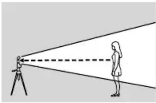
natural_image
Diagram showing a person observing a light beam from a surveying instrument (no text or symbols present)To use the LED light
1 Press the MENU button (①) and select [LIGHT MODE].
2 Press the center button to turn on the LED light.
To turn it off, press the center button once again.
3 Adjust LED brightness with the control wheel.

- While the LED light of the flash unit is lit, the flash mode indicator (⚡) is not displayed on the camera (i.e. the camera flash is disabled).
- Depending on the camera, lens, and brightness settings for video shooting, the proper white balance may not be obtained. In such a case, adjust the balance on the camera.
• To turn off the LED light, press the MENU button.
Notes
Note that the LED beam may be obstructed by the lens end, depending on the size of the lens attached to the camera.
Firing a test-flash
You can fire a test-flash before you start photographing. If you intend to use a flash meter for manual flash photography (page 26), be sure to fire a test-flash.
When the TEST button (①) lights in orange, press the TEST button.
GB

- The orange-lit TEST button indicates that the flash unit is ready to fire.
- The flash power for a test-flash depends on the flash power level specified for each flash mode. During TTL flash photography, this flash unit fires at the GN equivalent of 2.
- With the test-flash function, you can preview how the subject cast shadows (a modeling flash). On this flash unit, you can select [3TIMES] or [4SEC] (continuous flashes at consistent intervals for 4 seconds) for a modeling flash. To change the test-flash setting on the flash unit, press the MENU button, select [TEST], and then change the setting option.
- When [1TIME] or [GROUP] is specified for the test-flash setting, you can press and hold the TEST button to fire the specified number of test flashes with the specified flash frequency and power in MULTI flash mode.
- For radio wireless photography, you can press the test-flash button on the commander unit to force the receiver unit(s) to fire in accordance with the test-flash setting on the commander unit.
- If this flash unit is specified as the commander unit for radio wireless photography, the TEST button will light in orange when all the flash units, including the receiver units, are ready to fire.
Selecting the flash coverage (zoom)
Automatic selection of the flash coverage (auto zoom)
This flash unit automatically selects the appropriate flash coverage for the focal length of the lens on the attached camera within the range from 24 mm to 105 mm (auto zoom). You do not need to manually select the flash coverage most of the time.
When [AUTO] is displayed as the flash coverage (zoom) setting on the LCD panel, the auto zoom function is enabled.
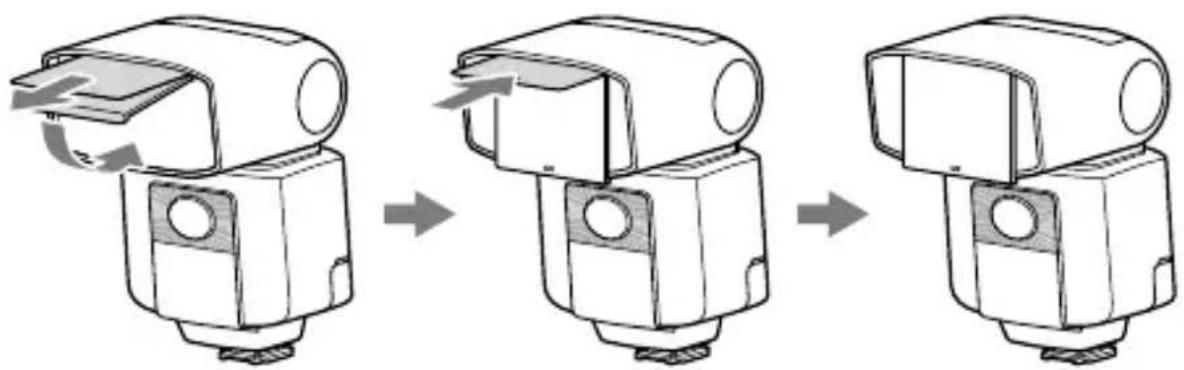
- If you use a lens with the focal length of less than 24 mm while the auto zoom function is enabled, [WIDE] will blink on the LCD panel.

In such a case, it is recommended that you use the built-in wide panel of this flash unit. To use the wide panel, gently pull out the wide panel along with the bounce sheet, fold down the wide panel to cover the flashtube, and then push the bounce sheet back into the flash unit.
natural_image
Three-step diagram showing a mechanical assembly process with arrows indicating motion (no text or symbols)• [WIDE] is displayed on the LCD panel.
- When you retract the wide panel, push it back all the way into the flash unit and make sure that [WIDE] is not displayed on the LCD panel.
- When you pull out the built-in wide panel, do not apply excessive force as it may cause damage to the wide panel.
- When you photograph the 2D subject from its front using a lens with the focal length of less than 18 ~mm , the periphery of the screen may appear slightly darker because of the difference in intensity of the flash light at the center and periphery of the screen.
- When you use a wide-angle lens with the focal length of less than 15 mm, the periphery of the screen may appear darker.
- The focal length displayed on the LCD panel indicates the equivalent 35mm-format focal length.
- This flash unit does not support the angle of view of a 16mm F2.8 Fisheye lens.
- Before storing this flash unit in the supplied case, be sure to push the wide panel and the bounce sheet back into the unit.
Manual selection of the flash coverage (manual zoom)
You can manually select the flash coverage of the flash unit regardless of the focal length of the lens in use (manual zoom). Press the ZOOM button (①) and select the flash coverage with the direction buttons.

Flash distribution setting
You can press the MENU button and select [FLASH DISTRIBUT.] to specify the flash distribution pattern. (The flash distribution setting is applied to the flash coverage whether it is selected automatically or manually.)

STD : Flash coverage with standard flash distribution CENTER : Flash coverage with priority given to guide numbers EVEN : Flash coverage with priority given to wider periphery
Notes
Depending on the focal length specified for photography, the periphery of the screen may appear darker. In such case, change the flash distribution pattern.
Bounce flash photography
By directing the flashtube of the flash unit at the ceiling or a wall of the room instead of directly at the subject, you can illuminate the subject with reflected light, reducing the intensity of the shadows and producing a softer light on the screen.

natural_image
Diagram showing a person using a surveying instrument to observe light rays from a camera, with another person observing (no text or symbols present)Tips
High-speed sync is available for bounce flash photography as well.
1 Tilt up or swivel the flashtube.

| Focal length of lens | Bounce angle |
| 70 mm minimum 30°, 45° | |
| 28 mm - 70 mm 60° | |
| 28 mm maximum 75°, 90° |
GB

Top view
2 Press the MODE button and select [TTL].
3 Press the shutter button to take a photo.
is displayed on the LCD panel of the flash unit to indicate bounce flash photography.
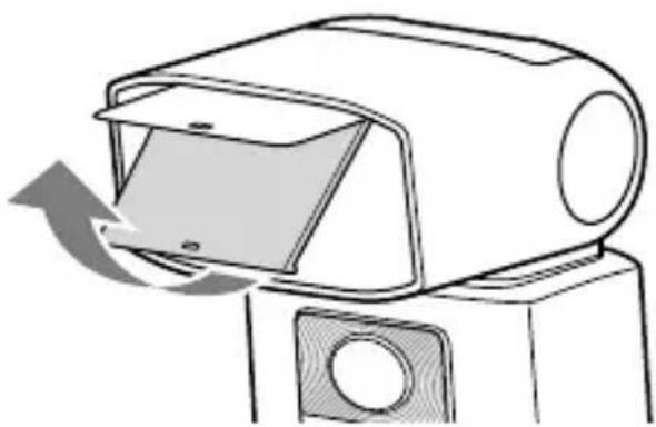
Using the bounce sheet
The bounce sheet creates a highlight in the subject's eyes and makes the subject look more vibrant.
1 Pull out the wide panel gently.
The bounce sheet is also pulled out. Push back the wide panel only.
natural_image
Line drawing of a device with a scroll wheel and arrow indicating motion (no text or symbols)2 Tilt up the flashtube by 90 degrees.
3 Press the MODE button and select [TTL].
4 Press the shutter button to take a photo.
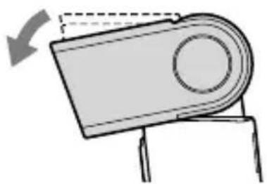
Close-up photography
Tilt down the flashtube slightly when photographing objects between 0.7 m and 1.0 m from the camera to ensure accurate illumination.

natural_image
Illustration of a camera emitting a light beam to a potted plant, no text or symbols present1 Tilt down the flashtube by 8 degrees.
natural_image
Simple line drawing of a mechanical component with an arrow indicating rotation (no text or symbols)- When photographing the subject located within 0.7 m, remove the flash unit from the camera and use it as an off-camera flash (not supplied) (page 39), or use a macro twin flash or a ring light (not supplied).
- When a lengthy lens is attached to the camera, the flash beam may be obstructed by the lens end.
About the AF illuminator
If the brightness or contrast setting of the camera is not sufficient for photographing the subject, the AF illuminator (LED light) on the front of the flash unit may light when you press the shutter button halfway down for auto-focusing. The AF illuminator is provided for aiding auto-focusing.
natural_image
Line drawing of a mechanical device with no visible text or symbols- The AF illuminator operates even when 📋 is displayed on the LCD panel.
- When you want to change the brightness of the AF illuminator, you can press the MENU button, select [AF LED LEVEL], and then [HIGH] or [LOW].
- To disable the AF illuminator, use the menu on the camera to turn it off.
- When the AF illuminator on the flash unit lights, the AF illuminator on the camera is disabled.
- While the camera is in Continuous AF mode (the camera is focusing on a moving subject), the AF illuminator does not light.
- If the focal length of the lens is greater than 300 mm, the AF illuminator may not light. In addition, when the flash unit is removed from the camera, the AF illuminator does not light.
- Depending on the camera to which the flash unit is attached, the AF illuminator may not light.
Assigning the custom keys
You can assign a function of your choice to some of the controls on the operation console: direction buttons, center button, and control wheel.
1 Press the MENU button (①) and select [CUSTOM KEY].

2 Select the control of your choice with the direction buttons.

3 Select the function that you want to assign.

| Groups | Assignable functions | Descriptions | Wheel and buttons | |||||
| Wheel | Center | Left | Right | Up | Down | |||
| # | MODE Flash mode setting - | ○ | ○ | ○ | ○ | ○* | ||
| #/LEVEL | Power level setting | ○ | ○ | ○* | ○ | ○ | ||
| ZOOM Flash coverage (zoom) setting | ○ | ○ | ○ | ○ | ○* | ○ | ||
| CMD/CTRL FLASH | Commander/Control unit flash setting | - | ○ | ○ | ○ | ○ | ||
| FLASH DISTRIBUT. | Flash distribution setting - | ○ | ○ | ○ | ○ | |||
| HSS High-speed sync setting - | ○ | ○ | ○ | ○ | ○ | |||
| RATIO CONTROL Lighting ratio setting - | ○ | ○ | ○ | ○ | ○ | |||
| RATIO VALUE Power level ratio setting - | ○ | ○ | ○ | ○ | ○ | |||
| MODE(GROUP) | Group flash mode setting | - | ○ | ○ | ○ | ○ | ||
| LIGHT MODE | LED light ON/OFF setting | - | ○ | ○ | ○ | ○ | ||
| RECALL | Memory Recall | - | ○ | ○ | ○ | ○ | ||
| MEMORY | Memory registration of a mode/setting value | - | ○ | ○ | ○ | ○ | ||
| ••• | WL MODE | Wireless mode setting | - | ○ | ○ | ○* | ○ | |
| RECEIVER SET | Receiver settings | - | ○ | ○ | ○ | ○ | ||
| GROUP | Wireless group setting | - | ○ | ○ | ○ | ○ | ||
| RCV REMOTE Rece | ver remote setting - | ○ | ○ | ○ | ○ | |||
| CH SET | Radio controlled wireless CH setting | - | ○ | ○ | ○ | ○ | ||
| ••CH SET | Optical controlled wireless CH setting | - | ○ | ○ | ○ | ○ | ||
| OTHERS | NOT SET | No setting | ○* | ○* | ○ | ○ | ○ | |
Registering/recalling the memory settings
You can register one of the modes that you frequently use or a combination of values to either [MR1] or [MR2].
To register
1 Press the MENU button and select [MEMORY].

2 Select [MR1] or [MR2].
To recall
1 Press the Fn button and select the item for recalling the memory setting.
GB

2 Select [MR1] or [MR2] with the control wheel.

- To change the memory setting, recall and change the setting, and then register the setting once again with [MEMORY].
- If you do not intend to use the registered memory setting, select [OFF].
- While the memory setting is recalled, [RESET] on the MENU settings screen is disabled.
Notes on use
While photographing
- This flash unit generates strong light, so it should not be used directly in front of the eyes.
- Do not use the flash 20 times in a row or in quick succession in order to prevent heating and degradation of the camera and flash unit. (when the power level is 1/32, 40 times in a row.) Stop using the flash unit and cool it for 10 minutes or more, if the flash is triggered up to the limit for the number of times in quick succession.
- During wireless photography, this flash unit may fire unexpectedly because the unit is unable to receive communication signals from an off-camera flash due to its location. In such a case, change the location of the off-camera flash or the wireless channel setting.
- Do not put this flash unit with the camera attached in the bag, etc. It may result in a malfunction of this flash unit or the camera.
- Do not carry this flash unit with the camera attached. It may result in a malfunction.
- Do not use the flash near people when rotating the flashtube during bounce
photography. The flash light may damage the eyes, or the hot flashtube may cause a burn.
- When rotating the flashtube, be careful not to catch your fingers in the rotating part. You may be injured.
- This camera is designed to be dust and moisture-resistant, but is not waterproof or splashproof.
- When closing the battery chamber door, press it firmly in while sliding it fully across. Be careful not to injure yourself by catching your finger in the battery chamber door when closing it.
Batteries
- The battery level displayed on the LCD panel may be lower than the actual battery capacity, due to temperature and storage conditions. The displayed battery level may be restored to the correct value after the flash has been used a few times.
- Nickel-metal hydride batteries can lose power suddenly. If the low-battery indicator starts blinking or the flash can no longer be used while taking pictures, change or recharge the batteries.
- Do not use lithium-ion batteries because repeated flash use makes the batteries hot and the flash will no longer fire.
- The flash frequency and number of flashes provided by new batteries may vary from the values shown in the table, depending on the time elapsed since manufacture of the batteries.
- Remove the batteries only after turning the power off and waiting several minutes, when changing the batteries. The batteries may be hot, depending on the battery type. Remove them carefully.
- Remove and store the batteries when you do not intend to use the camera for a long time.
Temperature
- The flash unit may be used over a temperature range of 0 °C to 40 °C.
- Do not expose the flash unit to extremely high temperatures (e.g. in direct sunlight inside a vehicle) or high humidity.
- To prevent condensation forming on the flash, place it in a sealed plastic bag when bringing it from a cold environment into a warm environment. Allow it to reach
room temperature before removing it from the bag.
- Battery capacity decreases at colder temperatures. Keep your camera and spare batteries in a warm inside pocket when shooting in cold weather. The low-battery indicator may blink even when there is some power left in the batteries in cold weather. Batteries will regain some of their capacity when warmed to normal operating temperature.
Maintenance
- Remove this unit from the camera. Clean the flash with a dry soft cloth. If the flash has been in contact with sand, wiping will damage the surface, and it should therefore be cleaned gently using a blower. In the event of stubborn stains, use a cloth lightly moistened with water or tepid water, and then wipe the unit clean with a dry soft cloth. Never use strong solvents, such as thinner or benzine, as these damage the surface finish.
- If fingerprints or debris are stuck to the lens or flashtube, we recommend that you gently remove any debris and then wipe the lens or flashtube clean with a soft cloth.
Specifications
Guide number
Normal flash/STD flash distribution (ISO 100)
Manual flash/35mm-format
| Power level | Flash coverage setting (mm) | ||||||
| 15* 24 | 28 35 50 | 70 105 | |||||
| 1/1 | 13 23 | 25 26 30 | 36 45 | ||||
| 1/2 | 9.2 16.3 | 17.7 18.4 | 21.2 25.5 | 31.8 | |||
| 1/4 | 6.5 11.5 | 12.5 13 15 | 18 22.5 | ||||
| 1/8 | 4.6 | 8.1 | 8.8 | 9.2 | 10.6 | 12.7 | 15.9 |
| 1/16 | 3.3 | 5.8 | 6.3 | 6.5 | 7.5 | 9 | 11.3 |
| 1/32 | 2.3 | 4.1 | 4.4 | 4.6 | 5.3 | 6.4 | 8 |
| 1/64 | 1.6 | 2.9 | 3.1 | 3.3 | 3.8 | 4.5 | 5.6 |
| 1/128 | 1.1 | 2 | 2.2 | 2.3 | 2.7 | 3.2 | 4 |
* When the wide panel is attached.
APS-C format
| Power level | Flash coverage setting (mm) | ||||||
| 15* 24 | 28 35 50 | 70 105 | |||||
| 1/1 | 13 24 | 26 30 36 | 41 45 | ||||
| 1/2 | 9.2 | 17 18.4 | 21.2 25.5 | 29 | 31.8 | ||
| 1/4 | 6.5 | 12 | 13 | 15 | 18 | 20.5 | 22.5 |
| 1/8 | 4.6 8.5 | 9.2 10.6 | 12.7 14.5 | 15.9 | |||
| 1/16 | 3.3 | 6 | 6.5 | 7.5 | 9 | 10.3 | 11.3 |
| 1/32 | 2.3 | 4.2 | 4.6 | 5.3 | 6.4 | 7.2 | 8 |
| 1/64 | 1.6 | 3 | 3.3 | 3.8 | 4.5 | 5.1 | 5.6 |
| 1/128 | 1.1 | 2.1 | 2.3 | 2.7 | 3.2 | 3.6 | 4 |
* When the wide panel is attached.
HSS flat flash/STD flash distribution (ISO 100)
Manual flash/35mm-format
| Shutter speed | Flash coverage setting (mm) | ||||||
| 15* 24 | 28 35 50 | 70 105 | |||||
| 1/250 | 4.6 | 8.4 | 9.1 | 9.5 | 11.3 | 12.9 | 16 |
| 1/500 | 3.2 | 5.9 | 6.4 | 6.7 | 8 | 9.1 | 11.3 |
| 1/1000 | 2.3 4.2 | 4.6 4.8 5.7 | 6.4 8 | ||||
| 1/2000 | 1.6 3 3.2 | 3.4 4 4.6 | 5.7 | ||||
| 1/4000 | 1.1 | 2.1 | 2.3 | 2.4 | 2.8 | 3.2 | 4 |
| 1/8000 | 0.8 | 1.5 | 1.6 | 1.7 | 2 | 2.3 | 2.8 |
| 1/16000 | 0.6 | 1 | 1.1 | 1.2 | 1.4 | 1.6 | 2 |
* When the wide panel is attached.
APS-C format
| Shutter speed | Flash coverage setting (mm) | ||||||
| 15* 24 | 28 35 50 | 70 105 | |||||
| 1/250 | 4.6 8.7 | 9.5 11.3 1 | 2.9 | 15.3 16 | |||
| 1/500 | 3.2 | 6.2 | 6.7 | 8 | 9.1 | 10.8 | 11.3 |
| 1/1000 | 2.3 | 4.4 | 4.8 | 5.7 | 6.4 | 7.7 | 8 |
| 1/2000 | 1.6 3.1 | 3.4 4 4.6 | 5.4 5.7 | ||||
| 1/4000 | 1.1 | 2.2 | 2.4 | 2.8 | 3.2 | 3.8 | 4 |
| 1/8000 | 0.8 | 1.5 | 1.7 | 2 | 2.3 | 2.7 | 2.8 |
| 1/16000 | 0.6 | 1.1 | 1.2 | 1.4 | 1.6 | 1.9 | 2 |
* When the wide panel is attached.
Radio wireless features:
Frequency band: 2.4 GHz
Number of channels: 14 channels
Communication distance: Approximately 30 m (98.4 ft.) (Acquired under our measurement conditions.)
- The distance given above applies under conditions where there are no obstacles, shielding, or radio wave interferences.
- The communication distance may be shorter depending on the positioning of the products, the ambient environment, and weather conditions.
Frequency/Repetition
| Alkaline Nickel hydride | |
| Frequency (sec) Approx. 0.1 - 2.5 Approx. 0.1 - 2.0 | |
| Repetition (times) Approx. 210 or more Approx. 270 or more | |
- Repetition is the approximate number of times that are possible before new batteries are completely dead.
Flash control Flash control using pre-flash (P-TTL/ADI)
Continuous flash 40 flashes at 10 flashes per second
performance (Normal flash, power level 1/32, 105 mm, nickel-metal hydride battery)
AF illuminator Autoflash at low contrast and low brightness
Operating range (While a 50mm lens with the aperture set at F5.6 is attached and [AF LED LEVEL] of the flash unit is specified as [HIGH]) Central area (Approx.): 0.5 m to 6 m (1 ft. 7 3/4 in. to 19 ft. 8 1/4 in.) Peripheral areas (Approx.): 0.5 m to 3 m (1 ft. 7 3/4 in. to 9 ft. 10 1/8 in.)
| LED light Center luminance intensity: Approx. 400 lx at 0.5 m(1 ft. 7 3/4 in.) or approx. 100 lx at 1 m (3 ft. 3 3/8 in.)Lighting distance: Approx. 1 m (3 ft. 3 3/8 in.)(when recording movies, set to ISO 3200 & F5.6)Focal length supported: 35 mm (35mm-format angle of view)Continuous lighting time: Approx. 4 hours (using AA alkaline batteries, at center luminance intensity)Color temperature: Approx. 5,500K | |
| Operating temperature | 0 °C to 40 °C (32 °F to 104 °F) |
| Storage temperature | -20 °C to +60 °C (-4 °F to +140 °F) |
| Dimension (Approx.) | 69.4 mm × 113.7 mm × 88.3 mm (2 3/4 in. × 4 1/2 in. × 3 1/2 in.) (w/h/d) |
| Mass (Approx.) | 317 g (11.2 oz) (excluding the batteries) |
| Power requirements | DC 6 V |
| Recommended batteries | Four LR6 (AA-size) alkaline batteriesFour AA-size rechargeable nickel-metal hydride batteries |
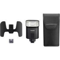
| Included items | Flash unit (1), Connector protect cap (1), Mini-stand (stored in the carrying case) (1), Carrying case (1), Set of printed documentationThe number in the parentheses indicates the quantity. |
Functions in these operating instructions depend on testing conditions at our firm.
Design and specifications are subject to change without notice.
Trademarks
"Multi Interface Shoe" is a trademark of Sony Corporation.
Français
http://www.sony.net/flash/f45rm/
FR
natural_image
Technical line drawing of a mechanical device with cylindrical components and a housing (no text or symbols)Remarques
natural_image
Black-and-white close-up of white flowering plants with blurred foliage background (no text or symbols)natural_image
Black-and-white close-up of white flowers with green foliage in the background (no text or symbols visible)natural_image
Black and white photo of a row of folded paper or paper sheets against a dark background (no text or symbols visible)natural_image
Illustration of three camera models and a potted plant, no text or symbols presentnatural_image
Illustration of three different photography equipment icons: a camera, a potted plant, and a camera with a base (no text or symbols)natural_image
Illustration of a person observing from a surveying instrument with a dashed light beam (no text or symbols)flowchart
graph LR
    A["Device with arrow indicating rotation"] --> B["Step 1: Rotation to left arm"]
    B --> C["Step 2: Rotation to right arm"]
    C --> D["Step 3: Rotation to right arm"]
natural_image
Diagram showing a person using a surveying instrument to observe light rays from a camera, with another person observing (no text or symbols present)Conseils
natural_image
Line drawing of a device with a paper clip and arrow indicating motion (no text or symbols)natural_image
Illustration of a robotic arm projecting a potted plant to reflect light (no text or symbols)natural_image
Simple line drawing of a mechanical component with an arrow indicating direction (no text or symbols)natural_image
Line drawing of a mechanical device with no visible text or symbolsFR
The OpenSSL toolkit stays under a dual license, i.e. both the conditions of the OpenSSL License and the original SSLeay license apply to the toolkit. See below for the actual license texts. Actually both licenses are BSD-style Open Source licenses. In case of any license issues related to OpenSSL please contact openssl-core@openssl.org.
OpenSSL License
/ ^*
* Copyright (c) 1998-2011 The OpenSSL Project. All rights reserved.
* Redistribution and use in source and binary forms, with or without * modification, are permitted provided that the following conditions * are met:
* 1. Redistributions of source code must retain the above copyright * notice, this list of conditions and the following disclaimer.
* 2. Redistributions in binary form must reproduce the above copyright * notice, this list of conditions and the following disclaimer in * the documentation and/or other materials provided with the * distribution.
* 3. All advertising materials mentioning features or use of this software must display the following acknowledgment: * "This product includes software developed by the OpenSSL Project for use in the OpenSSL Toolkit. (http://www.openssl.org/)"
* 4. The names "OpenSSL Toolkit" and "OpenSSL Project" must not be used to * endorse or promote products derived from this software without * prior written permission. For written permission, please contact * openssl-core@openssl.org.
* 5. Products derived from this software may not be called "OpenSSL" * nor may "OpenSSL" appear in their names without prior written * permission of the OpenSSL Project.
* 6. Redistributions of any form whatsoever must retain the following * * acknowledgment: * "This product includes software developed by the OpenSSL Project * for use in the OpenSSL Toolkit (http://www.openssl.org/)
* THIS SOFTWARE IS PROVIDED BY THE OpenSSL PROJECT ``AS IS'' AND ANY * EXPRESSED OR IMPLIED WARRANTIES, INCLUDING, BUT NOT LIMITED TO, THE * IMPLIED WARRANTIES OF MERCHANTABILITY AND FITNESS FOR A PARTICULAR * PURPOSE ARE DISCLAIMED. IN NO EVENT SHALL THE OpenSSL PROJECT OR
* ITS CONTRIBUTORS BE LIABLE FOR ANY DIRECT, INDIRECT, INCIDENTAL,
* SPECIAL, EXEMPLARY, OR CONSEQUENTIAL DAMAGES (INCLUDING, BUT
* NOT LIMITED TO, PROCUREMENT OF SUBSTITUTE GOODS OR SERVICES;
* LOSS OF USE, DATA, OR PROFITS; OR BUSINESS INTERRUPTION)
* HOWEVER CAUSED AND ON ANY THEORY OF LIABILITY, WHETHER IN CONTRACT,
* STRICT LIABILITY, OR TORT (INCLUDING NEGLIGENCE OR OTHERWISE)
* ARISING IN ANY WAY OUT OF THE USE OF THIS SOFTWARE, EVEN IF ADVISED
* OF THE POSSIBILITY OF SUCH DAMAGE.
* This product includes cryptographic software written by Eric Young
* (eay@cryptsoft.com). This product includes software written by Tim
* Hudson (tjh@cryptsoft.com).
*/
Original SSLeay License
/* Copyright (C) 1995-1998 Eric Young (eay@cryptsoft.com)
* All rights reserved.
*
* This package is an SSL implementation written
* by Eric Young (eay@cryptsoft.com).
* The implementation was written so as to conform with Netscapes SSL.
*
* This library is free for commercial and non-commercial use as long as
* the following conditions are aheared to. The following conditions
* apply to all code found in this distribution, be it the RC4, RSA,
* Ihash, DES, etc., code; not just the SSL code. The SSL documentation
* included with this distribution is covered by the same copyright terms
* except that the holder is Tim Hudson (tjh@cryptsoft.com).
*
* Copyright remains Eric Young's, and as such any Copyright notices in
* the code are not to be removed.
* If this package is used in a product, Eric Young should be given attribution
* as the author of the parts of the library used.
* This can be in the form of a textual message at program startup or
* in documentation (online or textual) provided with the package.
*
* Redistribution and use in source and binary forms, with or without
* modification, are permitted provided that the following conditions
* are met:
* 1. Redistributions of source code must retain the copyright
* notice, this list of conditions and the following disclaimer.
* 2. Redistributions in binary form must reproduce the above copyright
* notice, this list of conditions and the following disclaimer in the
* documentation and/or other materials provided with the distribution.
* 3. All advertising materials mentioning features or use of this software
* must display the following acknowledgement:
* "This product includes cryptographic software written by
* Eric Young (eay@cryptsoft.com)"
* The word 'cryptographic' can be left out if the rouines from the library
* being used are not cryptographic related :-).
* 4. If you include any Windows specific code (or a derivative thereof) from
* the apps directory (application code) you must include an acknowledgement:
* "This product includes software written by Tim Hudson (tjh@cryptsoft.com)"
*
* THIS SOFTWARE IS PROVIDED BY ERIC YOUNG ``AS IS'' AND
* ANY EXPRESS OR IMPLIED WARRANTIES, INCLUDING, BUT NOT LIMITED TO, THE
* IMPLIED WARRANTIES OF MERCHANTABILITY AND FITNESS FOR A PARTICULAR
* PURPOSE ARE DISCLAIMED. IN NO EVENT SHALL THE AUTHOR OR
* CONTRIBUTORS BE LIABLE FOR ANY DIRECT, INDIRECT, INCIDENTAL, SPECIAL,
* EXEMPLARY, OR CONSEQUENTIAL DAMAGES (INCLUDING, BUT NOT LIMITED
* TO, PROCUREMENT OF SUBSTITUTE GOODS OR SERVICES; LOSS OF USE, DATA,
* OR PROFITS; OR BUSINESS INTERRUPTION) HOWEVER CAUSED AND ON ANY
* THEORY OF LIABILITY, WHETHER IN CONTRACT, STRICT LIABILITY, OR TORT
* (INCLUDING NEGLIGENCE OR OTHERWISE) ARISING IN ANY WAY OUT OF THE
* USE OF THIS SOFTWARE, EVEN IF ADVISED OF THE POSSIBILITY OF SUCH DAMAGE.
*
* The licence and distribution terms for any publicly available version or
* derivative of this code cannot be changed. i.e. this code cannot simply be
* copied and put under another distribution licence
* [including the GNU Public Licence.]
*/


- Update the software of your camera to the latest version before use.
- WARNING
- CAUTION
- Notice
- For Customers in the U.S.A.
- Regulatory Information
- Declaration of Conformity
- Note:
- For Customers in Canada
- For Customers in Europe
- CE
- Disposal of Old Electrical & Electronic Equipment (Applicable
- in the European Union and other European countries with separate collection systems)
- For Customers in Singapore
- For Customers in Malaysia
- Table of Contents
- Preparations....13
- Settings 20
- Photographing....24
- Others 52
- Before use
- Notes on continuous flashes
- Do not place this flash unit in the following locations
- Communication distance
- Identifying parts
- Operation console
- About the LCD backlight
- On-screen indicators
- Inserting batteries
- Attaching/removing the flash unit to/from the camera
- To remove the flash unit from the camera
- Notes
- Turning on the power of the flash unit
- Turn on the power switch.
- Power-saving mode
- Checking the remaining battery power
- Pairing with a radio wireless commander/receiver (for radio wireless flash photography)
- Tips
- Select [OK] to establish pairing.
- To establish a pairing with 2 or more devices
- Quick Navi settings
- Press the Fn button (①).
- Select the setting item of your choice with the direction buttons.
- Rotate the control wheel to change the setting option.
- Press the Fn button.
- MENU settings
- Press the MENU button (①).
- Move the focus to the setting item of your choice with the direction buttons, and then press the center button.
- Change the setting option with the direction buttons and press the center button.
- Photographing
- Selecting the flash mode
- TTL flash photography
- Select the flash mode.
- Press the shutter button to take a photo.
- Auto WB adjustment with color temperature information
- TTL\*-flash mode
- Manual flash photography (MANUAL)
- High-speed sync photography (HSS)
- Flash sync speed
- Multiple flash photography (MULTI)
- Set the shutter speed and the aperture on the camera.
- Make sure that the flash unit is ready to fire, and then press the shutter button to take a photo.
- Maximum number for repetition in multiple flash
- Wireless flash photography (with radio or optical communications)
- Radio wireless flash photography
- Optical wireless flash photography
- Press the MENU button (①) and select [•/• SELECT] with the direction buttons.
- Select the wireless communication method of your choice.
- Attaching and removing the mini-stand
- Wireless flash photography (with radio wireless communications)
- Wireless flash photography (with the receiver unit)
- Select wireless (WL) flash mode on the camera.
- Make sure that the flash unit on the camera (commander unit) and this flash unit are wirelessly connected and ready to fire.
- Press the shutter button to take a photo.
- Multiple wireless flash photography with lighting ratio control
- To set the lighting ratio of the commander unit
- Multiple wireless flash photography (group flash photography)
- To set up for group flash photography
- Changing the settings of individual receiver units (RECEIVER SET)
- Notes on wireless flash photography with radio wireless communications
- Wireless flash photography (with optical wireless communications)
- Wireless flash photography (with the remote unit)
- Attach this flash unit to the camera and turn on the power of both devices.
- Select wireless (WL) flash mode on the camera.
- Remove the flash unit from the camera (page 14) and attach the mini-stand to the unit (page 32).
- Release the built-in flash of the camera or attach another flash unit to the camera.
- Place the camera and this flash unit.
- Make sure that the flash on the camera (controller unit) and this flash unit are ready to fire.
- Press the shutter button to take a photo.
- To set the lighting ratio of the controller unit
- Notes on wireless flash photography with optical wireless communications
- Illuminating for video shooting (LED light)
- To use the LED light
- Press the MENU button (①) and select [LIGHT MODE].
- Press the center button to turn on the LED light.
- Adjust LED brightness with the control wheel.
- Firing a test-flash
- When the TEST button (①) lights in orange, press the TEST button.
- Selecting the flash coverage (zoom)
- Automatic selection of the flash coverage (auto zoom)
- Manual selection of the flash coverage (manual zoom)
- Flash distribution setting
- Bounce flash photography
- Tilt up or swivel the flashtube.
- Press the MODE button and select [TTL].
- Press the shutter button to take a photo.
- Using the bounce sheet
- Pull out the wide panel gently.
- Tilt up the flashtube by 90 degrees.
- Press the MODE button and select [TTL].
- Press the shutter button to take a photo.
- Close-up photography
- Tilt down the flashtube by 8 degrees.
- About the AF illuminator
- Assigning the custom keys
- Press the MENU button (①) and select [CUSTOM KEY].
- Select the control of your choice with the direction buttons.
- Select the function that you want to assign.
- Registering/recalling the memory settings
- To register
- To recall
- Notes on use
- While photographing
- Batteries
- Temperature
- Maintenance
- Specifications
- Guide number
- Radio wireless features:
- Trademarks
- Français
- Remarques
- Conseils
- OpenSSL License
- Original SSLeay License
Brand : SONY
Model : HVLF45RM
Category : Flash