
HVL-MT24AM - Flash SONY - Free user manual and instructions
Find the device manual for free HVL-MT24AM SONY in PDF.


| Product Type | Double macro flash kit (macro twin flash) |
| Brand | Sony |
| Model | HVL-MT24AM |
| Dimensions (controller) | 68 × 123 × 91 mm (w × h × d) |
| Dimensions (dual flash) | 43 × 41 × 37 mm (w × h × d) per unit |
| Weight (controller) | 235 g (without batteries) |
| Weight (dual flash) | 33 g per unit |
| Power supply | 4 AA batteries (alkaline, lithium or rechargeable Ni-MH) |
| Guide number (ISO 100, 1 tube, power 1/1) | 17 |
| Flash modes | TTL, manual (M), test flash, modeling lamp |
| Flash coverage (without diffuser) | 60° horizontal × 45° vertical (equiv. 35 mm) |
| Coverage with wide-angle diffuser | 78° horizontal × 60° vertical (equiv. 24 mm) |
| Special features | Adjustable arms (2 lengths, angles 60°/90°), wide-angle diffuser, soft diffuser, modeling lamp (40 flashes/s) |
| Supplied accessories | Controller, 2 dual flashes, bracket, 2 arms, adapter rings ∅49 mm and ∅55 mm, 2 wide-angle diffusers, 2 diffusers, 2 cord winders, cases |
| Operating temperature | 0°C to 40°C |
| Maintenance and cleaning | Clean with a soft dry cloth; for sand, blow first; avoid solvents |
| Safety | Do not expose to rain/moisture; do not disassemble (high voltage); remove batteries if shock or overheating; keep out of reach of children |
| General information | Use with macro lenses recommended; compatible with Sony α cameras; auto power off after 4 min (adjustable) |
Frequently Asked Questions - HVL-MT24AM SONY
User questions about HVL-MT24AM SONY
0 question about this device. Answer the ones you know or ask your own.
Ask a new question about this device
Download the instructions for your Flash in PDF format for free! Find your manual HVL-MT24AM - SONY and take your electronic device back in hand. On this page are published all the documents necessary for the use of your device. HVL-MT24AM by SONY.
USER MANUAL HVL-MT24AM SONY
Operating Instructions
Mode d'emploi
Bedienungsanleitung
Printed on 70% or more recycled paper using VOC (Volatile Organic
Compound)-free vegetable oil based ink.
HVL-MT24AM
© 2006 Sony Corporation Printed in Japan
English
Before operating the product, please read this manual thoroughly and retain it for future reference.
WARNING
To reduce fire or shock hazard, do not expose the unit to rain or moisture.
Tape over lithium battery contacts to avoid short-circuit when disposing of batteries, and follow local regulations for battery disposal.
Keep batteries or things that could be swallowed away from young children. Contact a doctor immediately if an object is swallowed.
Immediately remove the batteries and discontinue use if...
- the product is dropped or subjected to an impact in which the interior is exposed.
- the product emits a strange smell, heat, or smoke.
Do not disassemble. Electric shock may occur if a high voltage circuit inside the product is touched.
IMPORTANT SAFETY INSTRUCTIONS
When using your photographic equipment, basic safety precautions should always be followed, including the following:
Read and understand all instructions before using.
Close supervision is necessary when any appliance is used by or near children. Do not leave appliance unattended while in use.
Care must be taken as burns can occur from touching hot parts.
Do not operate appliance with a damaged cord or if the appliance has been dropped or damaged- until it has been examined by a qualified serviceman.
Let appliance cool completely before putting away. Loop cord loosely around appliance when storing.
To reduce the risk of electric shock, do not immerse this appliance in water or other liquids.
To reduce the risk of electric shock, do not disassemble this appliance, but take it to a qualified serviceman when service or repair work is required. Incorrect reassembly can cause electric shock when the appliance is used subsequently.
The use of an accessory attachment not recommended by the manufacturer may cause a risk of fire, electric shock, or injury to persons.
Batteries may become hot or explode due to improper use.
Use only the batteries specified in this instruction manual.
Do not install the batteries with the polarity (+/-) reversed.
Do not subject batteries to fire or high temperatures.
Do not attempt to recharge (except for rechargeable batteries), short or disassemble.
Do not mix, batteries of different types, brands or ages.
SAVE THESE INSTRUCTIONS
CAUTION
Do not touch the flashtube during operation, it may become hot when the flash fires.
Do not expose the batteries to excessive heat such as sunshine, fire or the like.
For customers in Europe

natural_image
Symbol of a trash bin crossed with no text or numbers, representing waste sorting or disposal (no text present)Disposal of Old Electrical & Electronic Equipment (Applicable in the European Union and other European countries with separate collection systems)
This symbol on the product or on its packaging indicates that this product shall not be treated as household waste. Instead it shall be handed over to the applicable collection point for the recycling of electrical and electronic equipment. By ensuring this product is disposed of correctly, you will help prevent potential negative consequences for the environment and human health, which could otherwise be caused by inappropriate waste handling of this product. The recycling of materials will help to conserve natural resources. For more detailed information about recycling of this product, please contact your local Civic Office, your household waste disposal service or the shop where you purchased the product.
< Notice for the customers in the countries applying EU Directives >
The manufacturer of this product is Sony Corporation, 1-7-1 Konan Minato-ku Tokyo, 108-0075 Japan. The Authorized Representative for EMC and product safety is Sony Deutschland GmbH, Hedelfinger Strasse 61, 70327 Stuttgart, Germany.
For any service or guarantee matters please refer to the addresses given in separate service or guarantee documents.
For the customers in the U.S.A.
CAUTION
You are cautioned that any changes or modifications not expressly approved in this manual could void your authority to operate this equipment.
NOTE:
This equipment has been tested and found to comply with the limits for a Class B digital device, pursuant to Part 15 of the FCC Rules.
These limits are designed to provide reasonable protection against harmful interference in a residential installation.
This equipment generates, uses, and can radiate radio frequency energy and, if not installed and used in accordance with the instructions, may cause harmful interference to radio communications.
However, there is no guarantee that interference will not occur in a particular installation. If this equipment does cause harmful interference to radio or television reception, which can be determined by turning the equipment off and on, the user is encouraged to try to correct the interference by one or more of following measures:
- Reorient or relocate the receiving antenna.
- Increase the separation between the equipment and receiver.
- Connect the equipment into an outlet on a circuit different from that to which the receiver is connected.
- Consult the dealer or an experienced radio/TV technician for help.
Table of contents
Features 6
Name of parts 7
Preparations
Inserting batteries 11
Attachment and removal of the macro flash controller .... 13
Attaching the macro twin flash 14
Auto power ON/OFF 21
Basics
Basic flash modes (A mode/M mode) ...... 22
Program auto flash (The basics) 30
Detailed operations
Manual flash (M) 32
Test flash 40
Modeling flash 41
Wide panel 42
Diffuser 44
Custom setting 48
Additional Information
Examples of macro twin flash photography .... 51
Aperture range graph .... 54
Compatibility with other products .... 56
Notes on use 57
Maintenance 58
Specifications.... 59
Before use
For details, refer to the operating instructions supplied with your camera.
This flash is not dust-proof, splash-proof or waterproof.
Do not place this flash in the following locations
Regardless of whether this unit is in use or in storage, do not place it in any of the following locations. Doing so may lead to a malfunction.
- Placing this flash in locations subject to direct sunlight such as on dashboards or near a heater may cause this unit to deform or malfunction.
- Locations with excessive vibration
- Locations with strong electromagnetism
- Locations with excessive sand In locations such as the seashore and other sandy areas or where dust clouds occur, protect the unit from sand and dust. This may lead to a malfunction.
Features
The macro twin flash kit provides flexible lighting for macro nature photography. It is ideal for close-up photography of flowers, insects, small objects, and so on.
- Freedom to change the attachment position and angle of the flashtube enables more expressive photography.
- Attaching two-length adjustable arms between the twin flash units and holders makes it possible to change the lighting for high magnification close-up photography.
- Using the supplied diffuser enables softer lighting.
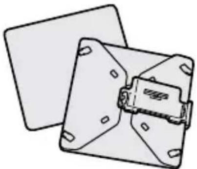
- The supplied wide panel expands flash coverage to a focal length of 24 mm.
- Modeling flash function can check shadows before photographing.
Name of parts
Macro Flash Controller

* Do not touch directly.
Control Panel

Macro Twin Flash
Twin Flash Unit*

Holder (14)

Arm* (17)

Adaptor ring (14)
∅49mm, ∅55mm

natural_image
Illustration of two overlapping rings (no text or symbols)Diffuser* (44) Wide panel* (42) Cord reel* (18)

natural_image
Technical line drawing of a mechanical component with mounting holes and a central internal structure (no text or symbols)
natural_image
Illustration of two computer monitors with ventilation grilles (no text or symbols)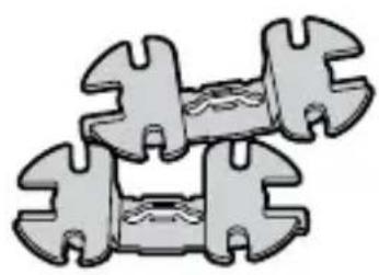
natural_image
Illustration of a mechanical component with interlocking parts and internal channels (no text or symbols)* Two supplied
Example of storage

Inserting batteries
The HVL-MT24AM may be powered by :
* Batteries are not supplied.
- Four AA-size alkaline batteries
- Four AA-size lithium batteries
- Four AA-size rechargeable nickel-metal hydride (Ni-MH) batteries
Always ensure that rechargeable nickel-metal hydride batteries are charged in the specified charger unit.
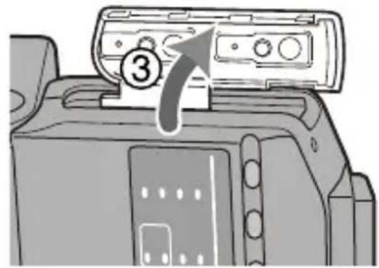
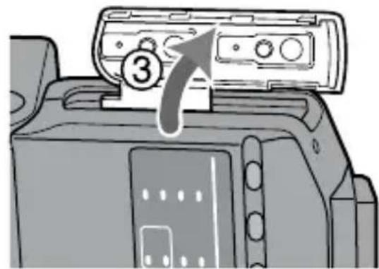
1 Open the battery-chamber door as shown.
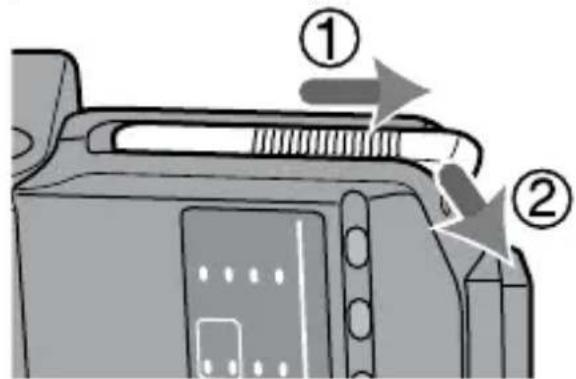
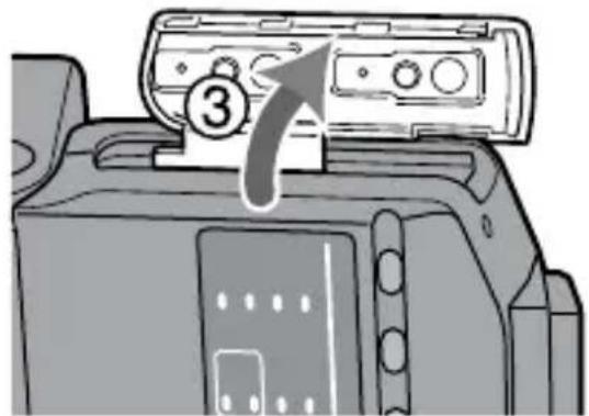
2 Insert the batteries in the battery chamber as in the diagram.

natural_image
Diagram of a camera module with four batteries and a display panel (no text or symbols)3 Close the battery-chamber door.
- Follow the reverse steps when opening the battery-chamber door.
- The lamp on the control panel comes on. If it does not come on, press the flash ON/OFF button.
Continuedonthenextpage
Checking Batteries
The clamp on the control panel comes on or blinks when the batteries are low.
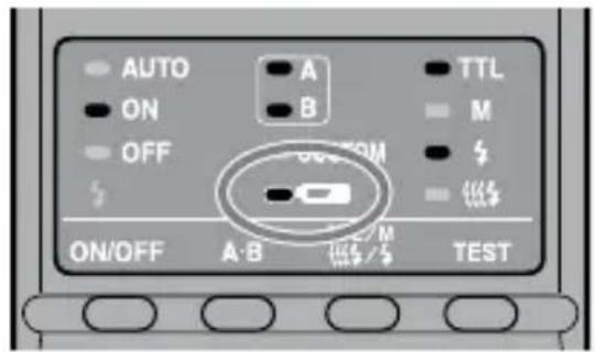
lamp on
Changing the batteries is recommended. The flash can still be used in this state if (Flash-ready lamp) on the rear of the unit is lit.

Only tap blinking
Flash cannot be used. Insert new batteries.
- If nothing comes on when the flash ON/OFF button of the macro flash controller is pressed, check the orientation of the batteries.
Attachment and removal of the macro flash controller
Attaching the macro flash controller to the camera
Push the mounting foot firmly onto the camera until it stops.
- The macro flash controller is locked in place automatically.
- If the built-in flash in the camera is protruding, lower it before attaching the macro flash controller.

natural_image
Diagram of a DSLR camera with an attached digital display and control buttons (no text or symbols)Removing the macro flash controller from the camera
While pressing the mounting foot release button ①, remove the macro flash controller ②.

Attaching the macro twin flash
1 Screw the appropriate adaptor ring clockwise onto the lens.
49mm and 55mm diameter adaptors are supplied.

natural_image
Line drawing of a DSLR camera with a coiled lens and scroll wheel (no text or symbols)2 While pressing the tabs on each side of the holder, place the holder over the adaptor, and then release both tabs.

natural_image
Technical illustration of a mechanical component with gear and mounting holes (no text or symbols)3 Remove the protective socket caps of the macro flash controller.
- For safe-keeping, place the caps in the case.
- Replace caps after use.

natural_image
Illustration of a portable electronic device with ports and a close-up of its right-hand grip (no text or symbols)4 Place the twin flash unit into the shoe of one of the holders.
Use of an arm is also possible (p. 17).

natural_image
Mechanical assembly diagram showing a tractor with gear and a valve (no text or symbols)5 Insert the plug of the twin flash unit into the twin-flash-cord socket on the macro flash controller.
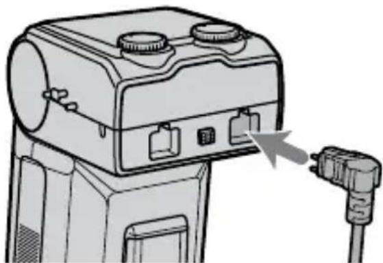
natural_image
Illustration of a camera with attached cable, showing ports and wiring (no text or symbols)Continuedonthenextpage
When removing the plug, press the twin flash-cord release button on the macro flash controller and pull the plug straight out of the socket.
Do not remove the plug by pulling on the connecting cord.
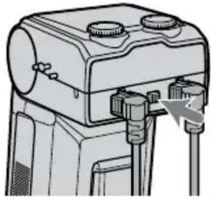
natural_image
Technical line drawing of a mechanical device with adjustment knobs and a scroll wheel (no text or symbols)6 Adjust positions of the flashtubes as desired.
- Each flashtube of the twin flash unit can be attached to any of the holder's four shoes.
• Each flashtube of the twin flash unit can be tilted.
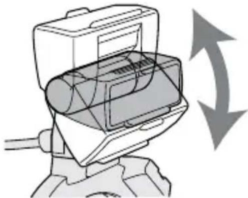
natural_image
Diagram of a mechanical device with directional arrows indicating rotation or movement (no text or symbols)- The holder can be rotated. Press the release tabs when removing or rotating the holder.

natural_image
Top-down schematic of a mechanical component with two arms and directional arrows indicating flow or movement (no text or symbols)Attaching the arm
You can use an arm to position the flash unit away from the lens.
1 Attach the arm by sliding its base into one of the four shoes on the holder.
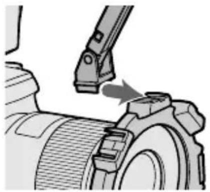
natural_image
Mechanical assembly diagram showing a lever interacting with a gear (no text or symbols visible)2 Attach the flashtube of the twin flash unit to the shoe of the arm.
3 Set the arm at either of two lengths.

natural_image
Technical line drawing of a mechanical device with lever and cable (no text or symbols)Continuedonthenextpage
4 When changing the angle to 60^ position, hold both ends of the arm and move it so that it clicks twice into place.
- The angle of the arm can be adjusted to either of two positions, 60^ or 90^ position.
- Although the arm can be moved past the 60^ and 90^ positions to prevent breakage, only use in these two positions. Also, do not attach the two arms in combination. Doing so may damage the arms.

natural_image
Technical illustration of two mechanical components mounted on a tire, showing different angles and mounting details (no text or symbols present)60° position 90° position
Using the cord reel
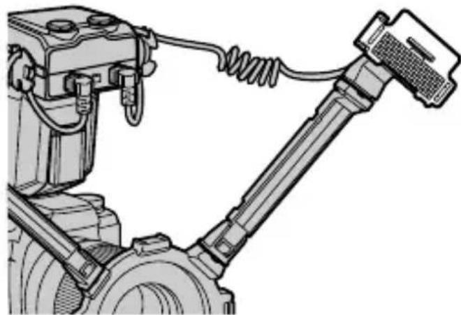
The cord reel can be attached to the side of the macro flash controller to take up slack in the connecting cord of the twin flash unit.
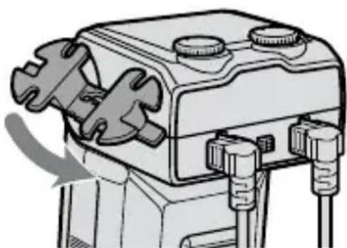
Attaching the cord reel to the macro flash controller
As illustrated, first check the up-down direction of the cord reel, and then attach the top of the cord reel followed by the bottom of the cord reel to the reel-attachment points on the side of the macro flash controller.
natural_image
Mechanical component diagram showing a lever mechanism with adjustment arrows (no text or symbols)Example of taking up the connecting cord
Secure the connecting cord slack by wrapping it around the reel and using the outer notches, as illustrated.

natural_image
Mechanical component with coiled spring and plug assembly, showing magnified detail (no text or symbols)Removing the cord reel
Pull the bottom of the cord reel away from the macro flash controller to remove it.

natural_image
Mechanical component diagram showing a gear mechanism with rotating shafts and mounting points (no text or symbols)Continuedonthenextpage
- By attaching the wide panel to the flashtube, the flash coverage angle can be increased (p. 42).
natural_image
Mechanical assembly diagram showing a linkage mechanism with hoses and components (no text or labels)- By using the diffuser attached to the flashtube, strong shadows can be softened. Always use the diffuser with an arm (p. 44).

natural_image
Technical line drawing of a mechanical robotic arm with a connecting rod and spring (no text or symbols)- Make sure the flashtube is pointing at the subject. Do not allow the cord to get in front of the flashtube or lens.
• See page 51 for photographic examples. - If an arm is used when taking extreme close-ups with a 50mm F2.8 Macro lens, the subject may not receive sufficient lighting (p. 53).
Auto power ON/OFF
Press the flash ON/OFF button on the back of the macro flash controller.
Power of the macro flash controller comes on.
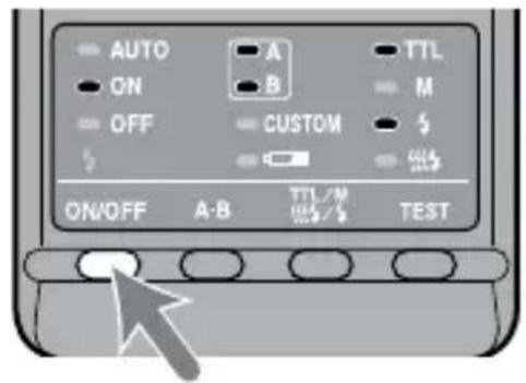
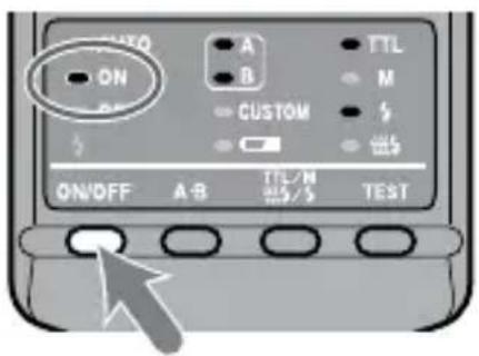
When the power of the macro flash controller is turned on, the flash-ON lamp on the control panel comes on.

If you press the flash ON/OFF button while the macro flash controller is turned on, the macro flash controller switches off and the flash-OFF lamp on the control panel comes on.
- The flash-OFF lamp goes out after about 10 seconds.
Auto power off
If the camera or macro flash controller is not used for four minutes, the power switches off and control panel indicators disappear automatically to save the batteries.
- You can disable auto power off or change the auto power off time by changing the customized settings (p. 48).
Basic flash modes (A mode/M mode)
Camera's exposure mode should be set to either A (aperture priority) mode ^1 , or M (manual) mode ^2 .
- In general close-up photography, the depth-of-field ^*3 must be quite shallow, which usually requires a smaller aperture when shooting. It is therefore better to select A or M mode, which enable you to select the aperture.
Using a macro lens is also recommended.
In this section, the basic flash operation in A or M mode with TTL metering (TTL lamp on) is described.
The following instructions from the next page assume that you are using one of the following cameras and macro lenses.
Camera: A camera with A (aperture priority) mode or M (manual) mode.
Lens: 50mm F2.8 Macro
100mm F2.8 Macro
If you photograph in P mode, refer to page 30. If using a different lens, see the aperture range graph on page 54.
^1 A mode: In A mode, you select the aperture and the camera automatically sets the shutter speed required for proper exposure.
^2 M mode: You can select both aperture and shutter speed. You can select a shutter speed that is slower than the camera’s sync speed.
*3 Depth-of-field: The range behind and in front of the subject that is sharply focused. In close-up photography, this range is shallower and the out-of-focus range is wider.
1 Set the POWER switch of the camera to ON and select A or M mode.
2 Press the flash ON/OFF button to turn on the flash-ON lamp on the control panel.

3 Focus your subject and check the magnification ratio.
You can check the magnification ratio with the magnification ratio scale on the lens. (The location of the magnification ratio scale differs depending on the lens.)
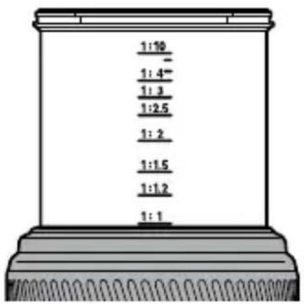
4 When using M mode, select a shutter speed.
You cannot select the shutter speed faster than the camera's sync speed.
5 Select the aperture.
To find the correct aperture number, refer to pages 26 to 29.
Continuedonthenextpage
6 Select the flash.
Press the A-B button on the back of the macro flash controller to turn on the twin flash A lamp, twin flash B lamp or both twin flash lamps. (The lit lamps indicate which flash will go off.)
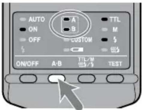
As viewed from the rear (control panel side), the A flash is connected to the left side socket and the B flash to the right side socket.
- For the effect of selecting the flash, see from page 51 to 53.

7 When the macro flash controller is charged, press the shutter button to take a photo.
The macro flash controller is charged when the flash-ready lamp on the control panel of the macro flash controller and the indicator in the camera viewfinder are both on.

When the correct exposure has been obtained for the photo just taken, the flash-ready lamp on the control panel blinks.
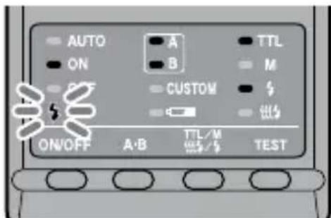
- The photo will be under-exposed if taken before charging is complete.
- The use of a tripod or remote cord is recommended to reduce camera shake.
- A camera-to-subject distance of less than 0.5m, and a magnification ratio of more than 0.15X (greater than 1:7), are recommended to get the best results from the macro flash units.
- Always turn off the macro flash controller if the twin flash unit is not connected. If the twin flash unit is not attached, but the controller is on, the camera flash sync will be in effect and the resulting ambient exposures will be incorrect.
- The camera's AF illuminator is blocked by the adaptor ring or twin flash unit and cannot be used for focusing.
Continuedonthenextpage
Selecting Apertures in TTL Flash
- The following tables show values when ISO 100 is used without the wide panel or diffuser. For other ISO speeds, or if you use the wide panel or diffuser, adjust the aperture settings according to the tables on page 28.
- The aperture ranges given in the tables are calculated values. The actual lens will have its own usable aperture range.
Example: Using a 50mm F2.8 Macro lens when ISO 100, with a pair of twin flash units with no arm, at a magnification ratio of 1:1
→ The range of acceptable apertures is calculated to be from f/4 to f/90 (refer to the following table).
However, the lens aperture range is f/2.8 to f/32, so the actual range possible with this lens is f/4 to f/32.
- The following tables show data for certain lenses and magnification ratios. For other lenses and magnification ratios, see page 54.
50mm F2.8 Macro (Lens aperture range : f/2.8 - f/32)
| Magnification ratio | 1:1 1:1.5 | 1:2 1:3 1:4 | |||
| Without arm | 4 ~ 90 | 5.6 ~ 128 | 8 ~ 180 | 5.6 ~ 128 | 4.5 ~ 108 |
| 2.8 ~ 64 | 4 ~ 90 | 5.6 ~ 128 | 4 ~ 90 | 3.5 ~ 76 | |
| Arm (short) | 2.4 ~ 54 | 2.8 ~ 64 | 4 ~ 90 | 4 ~ 90 | 4.5 ~ 108 |
| 60° position | 1.7 ~ 38 | 2 ~ 45 | 2.8 ~ 64 | 2.8 ~ 64 | 3.5 ~ 76 |
| Arm (long) | 1.4 ~ 32 | 1.4 ~ 32 | 2 ~ 45 | 2.4 ~ 54 | 2.8 ~ 64 |
| 90° position | 1 ~ 22 | 1 ~ 22 | 1.4 ~ 32 | 1.7 ~ 38 | 2 ~ 45 |
Upper set of numbers is for two twin flash units.
Lower set is for one twin flash unit.
100mm F2.8 Macro (Lens aperture range : f/2.8 - f/32)
| Magnification ratio | 1:1 1:1.5 | 1:2 1:3 | ||
| Without arm | 3.5 ~ 76 | 3.5 ~ 76 | 2.8 ~ 64 | 2.4 ~ 54 |
| 2.4 ~ 54 | 2.4 ~ 54 | 2 ~ 45 | 1.7 ~ 38 | |
| Arm (short) | 2 ~ 45 | 2.8 ~ 64 | 2.8 ~ 64 | 2.8 ~ 64 |
| 60° position | 1.4 ~ 32 | 2 ~ 45 | 2 ~ 45 | 2 ~ 45 |
| Arm (long) | 1.2 ~ 27 | 1.7 ~ 38 | 2 ~ 45 | 2 ~ 45 |
| 90° position | 0.85 ~ 19 | 1.2 ~ 27 | 1.4 ~ 32 | 1.4 ~ 32 |
Upper set of numbers is for two twin flash units. Lower set is for one twin flash unit.
Continuedonthenextpage
When using other than ISO 100, or when using the wide panel or diffuser
An additional adjustment must be applied to the previous tables.
| Without wide panel or diffuser (Exposure adjustment) | With wide panel (Exposure adjustment) | With diffuser (Exposure adjustment) | |
| ISO 25 + | 2 Stop +3.5 Stop +4.5 Stop | ||
| ISO 50 + | 1 Stop +2.5 Stop +3.5 Stop | ||
| ISO 100 No change +1.5 Stop +2.5 Stop | |||
| ISO 200 -1 Stop +0.5 Stop +1.5 Stop | |||
| ISO 400 -2 Stop -0.5 Stop +0.5 Stop | |||
| ISO 800 -3 Stop -1.5 Stop -0.5 Stop | |||
| ISO 1600 -4 Stop -2.5 Stop -1.5 Stop | |||
f/stop scale

tree
| Level | Value | |---|---| | a full-stop | 180 | | a half-stop | 152 | | a full-stop | 128 | | a half-stop | 108 | | a full-stop | 90 | | a half-stop | 76 | | a full-stop | 64 | | a half-stop | 54 | | a full-stop | 45 | | a half-stop | 38 | | a full-stop | 32 | | a half-stop | 27 | | a full-stop | 22 | | a half-stop | 19 | | a full-stop | 16 | | a half-stop | 13 | | a full-stop | 11 | | a half-stop | 9.5 | | a full-stop | 8 | | a half-stop | 6.7 | | a full-stop | 5.6 | | a half-stop | 4.5 | | a full-stop | 4 | | a half-stop | 3.5 | | a full-stop | 2.8 | | a half-stop | 2.4 | | a full-stop | 2 | | a half-stop | 1.7 | | a full-stop | 1.4 | | a half-stop | 1.2 | | a full-stop | 1 | | a half-stop | 0.85 | Decrease exposure Increase exposure ↑ ↓Using the f/stop scale
Using the f/stop scale at the left, moving one step vertically is equal to a full-stop change. Moving one step diagonally is equal to a half-stop change.
Half a stop is basic for setting the aperture in this step. When using a 0.3 stop setting camera, adjust the aperture by a value as close as possible to a value in the above table and use the aperture around the f/stop scale. For precise photography, bracketing is recommended.
Example:
Starting at f/8, if you decrease the exposure by a full stop, you get f/11. If you increase by half a stop, you get f/6.7.
Selecting the aperture when using other than ISO 100, or when using the wide panel or diffuser
1 Check the calculated acceptable aperture range under the same condition with ISO 100 by using the table on page 27.
2 Check the additional adjustment when using other than ISO 100 or when using the wide panel or diffuser by using the table on page 28.
3 Check the calculated acceptable aperture range by using the f/stop scale using the results of step1 and step2.
4 Apply the result of step3 to the actual aperture range for this particular lens and select the usable range for satisfactorily results.
Example: Using a 50mm F2.8 Macro lens, two twin flash units, no arm, magnification ratio of 1:2, and ISO 200
1 Check the calculated acceptable aperture range when using a 50mm F2.8 Macro lens, two twin flash units, no arm, magnification ratio of 1:2, and ISO 100. →f/8 - f/180 (refer to the table on page 27)
2 Check the additional adjustment when using ISO 200 and diffuser by using the table on page 28.
→Increase the aperture by +1.5 stops (refer to the table on page 28).
3 The aperture increased by +1.5 stops from f/8 is equal to f/4.5, and the aperture increased by +1.5 stops from f/180 is equal to f/108.
4 The actual aperture range for a 50mm F2.8 Macro lens is f/2.8 - f/32, so the upper limit of the adjusted f/4.5 - f/108 range, i.e. f/108, is beyond the range that can be set. The usable range for satisfactorily results is therefore f/4.5 - f/32.
Program auto flash (The basics)
The procedure for P mode, including subject program selection, is the same as that for A or M mode, except that the aperture is set automatically.
1 Set the POWER switch of the camera to ON and select P mode.
2 Press the flash ON/OFF button to turn on flash-ON lamp on the control panel.

3 Focus your subject and check the magnification ratio.
4 Select the flash.

5 When the macro flash controller is charged, press the shutter button to take a photo.
- With some cameras, the flash will fire automatically in P mode. In this case, the auto lamp on the macro flash unit comes on and the flash may not fire if the surrounding conditions are bright.

- The P mode flash program is designed for general subjects, not macro subjects. When taking macro photos, the depth-of-field may be very shallow. If the aperture selected by the camera is outside the allowable range, the proper exposure cannot be obtained (p. 26 - 29).
Manual flash (M)
Normal TTL flash metering automatically adjusts the flash intensity to provide the proper exposure for the subject. Manual flash provides a fixed flash intensity irrespective of the brightness of the subject and the camera setting.
- In manual flash mode, the maximum flash power is when the manual flash control is set to 1/1. Each step of the flash power level corresponds to one aperture stop. Changing the setting by one stop, for example from 1/1 to 1/2, is equivalent to decreasing the aperture one stop, for example from f/4 to f/5.6.
- Manual flash can only be used when the camera is in the M mode. In other modes, TTL measuring is automatically selected.
- As manual flash is not affected by the reflectivity of the subject, it is convenient for use with subjects with extremely high or low reflectivity.

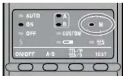
TTL flash metering Manual flash metering
1 Select M mode on the camera.
2 Press the TTL/M/Test button to light on the M (manual-flash control) lamp.
The modes change in the following order. (Test flash (p. 40), Modeling flash (p. 41))

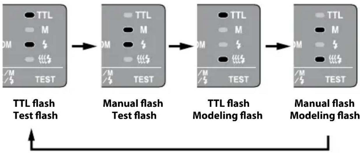
flowchart
graph LR
    A["TTL flash Test flash"] --> B["Manual flash Test flash"]
    B --> C["TTL flash Modeling flash"]
    C --> D["Manual flash Modeling flash"]
3 Select shutter speed and aperture (p. 34 - 39).
4 Turn the appropriate manual-flash-control dial and select the desired power level (p. 34 - 39).
- When viewed from the rear (control panel side), the manual-flash-control dial for twin flash A is on the left, and that for twin flash B is on the right. You can select any power level setting on the upper scale from 1/1 to 1/64.

- In manual flash mode, if a proper exposure has been obtained, the flash-ready lamp will not blink on the control panel after a photo is taken.
- Using customized functions, manual flash may be selected without setting the camera in M mode. The size of the steps on the manual-flash-control dials can also be changed from full-stop increments to half-stop increments (p. 48).
Continuedonthenextpage
Selecting apertures and power level in manual flash
- The following tables show the values when ISO 100 is used without the wide panel or diffuser. For other ISO speeds, or if you use the wide panel or diffuser, adjust the aperture settings according to the table on page 38. When using the twin flash units, the data assumes that the power lever is the same for both units. If they are set at different power levels, see page 37.
- The aperture values given in the tables are calculated values. The actual lens will have its own usable aperture range.
Example: Using a 50mm F2.8 Macro lens when ISO 100, with a pair of twin flash units with no arm, power level of 1/1, and a magnification ratio of 1:1
→ The aperture is calculated at f/90 (refer to the following table). However, the smallest actual aperture possible with this lens is f/32. Therefore, if you set the power level to 1/1, the picture will be overexposed. But if you set the power level to 1/8, you will get a correct exposure at f/32.
- These following tables show the apertures where the proper exposure of the illuminated area is obtained. Actual exposure varies according to the subject's shape or position (p. 53). Test photographs or bracketing is recommended especially when the subject is illuminated from side or behind.
- The following tables show data for certain lenses and magnification ratios. For other lenses and magnification ratios, see page 55.
50mm F2.8 Macro (Lens aperture range: f/2.8 - f/32)
| Magnification ratio | 1:1 1:1.5 | 1:2 1:3 1:4 | ||||
| Power level | ||||||
| Without arm | 1/1 90 (64) | 128 (90) 1 | 80 (128) 12 | 8 (90) 108 | (76) | |
| 1/2 64 (45) | 90 (64) 12 | 8 (90) 90 (64) | 76 (54) | |||
| 1/4 45 (32) | 64 (45) 90 | (64) 64 (45) | 54 (38) | |||
| 1/8 32 (22) | 45 (32) 64 | (45) 45 (32) | 38 (27) | |||
| 1/16 22 (16) | 32 (22) 45 | (32) 32 (22) | 27 (19) | |||
| 1/32 16 (11) | 22 (16) 32 | (22) 22 (16) | 19 (13) | |||
| 1/64 11 (8) | 16 (11) 22 | (16) 16 (11) | 13 (9.5) | |||
| Arm(short) 60^ position | 1/1 54 (38) | 64 (45) 90 | (64) 90 (64) | 108 (76) | ||
| 1/2 38 (27) | 45 (32) 64 | (45) 64 (45) | 76 (54) | |||
| 1/4 27 (19) | 32 (22) 45 | (32) 45 (32) | 54 (38) | |||
| 1/8 19 (13) | 22 (16) 32 | (22) 32 (22) | 38 (27) | |||
| 1/16 13 (9.5) | 16 (11) 22 | (16) 22 (16) | 27 (19) | |||
| 1/32 9.5 (6.7) | 11 (8) 16 | (11) 16 (11) | 19 (13) | |||
| 1/64 6.7 (4.5) | 8 (5.6) 1 | 1 (8) 11 (8) | 13 (9.5) | |||
| Arm(long) 90^ position | 1/1 32 (22) | 32 (22) 45 | (32) 54 (38) | 64 (45) | ||
| 1/2 22 (16) | 22 (16) 32 | (22) 38 (27) | 45 (32) | |||
| 1/4 16 (11) | 16 (11) 22 | (16) 27 (19) | 32 (22) | |||
| 1/8 | 11 (8) 11 | (8) 16 (11) | 19 (13) 22 | (16) | ||
| 1/16 | 8 (5.6) 8 | (5.6) 11 (8) | 13 (9.5) 16 | (11) | ||
| 1/32 | 5.6 (4) 5.6 | (4) 8 (5.6) | 9.5 (6.7) | 11 (8) | ||
| 1/64 | 4 (2.8) 4 | (2.8) 5.6 (4) | 6.7 (4.5) | 8 (5.6) |
Use aperture values inside ( ) when only one twin flash unit is used.
100mm F2.8 Macro (Lens aperture range: f/2.8 - f/32)
| Magnification ratio | 1:1 1:1.5 | 1:2 1:3 | |||
| Power level | |||||
| Without arm | 1/1 76 (54) | 76 (54) 64 | (45) 54 (38) | ||
| 1/2 54 (38) | 54 (38) 45 | (32) 38 (27) | |||
| 1/4 38 (27) | 38 (27) 32 | (22) 27 (19) | |||
| 1/8 27 (19) | 27 (19) 22 | (16) 19 (13) | |||
| 1/16 19 (13) | 19 (13) 16 | (11) 13 (9.5) | |||
| 1/32 13 (9.5) | 13 (9.5) | 11 (8) 9.5 (6.7) | |||
| 1/64 9.5 (6.7) | 9.5 (6.7) | 8 (5.6) 6.7 | (4.5) | ||
| Arm(short) 60^ position | 1/1 45 (32) | 64 (45) 64 | (45) 64 (45) | ||
| 1/2 32 (22) | 45 (32) 45 | (32) 45 (32) | |||
| 1/4 22 (16) | 32 (22) 32 | (22) 32 (22) | |||
| 1/8 16 (11) | 22 (16) 22 | (16) 22 (16) | |||
| 1/16 11 (8) | 16 (11) 16 | (11) 16 (11) | |||
| 1/32 8 (5.6) | 11 (8) 11 | (8) 11 (8) | |||
| 1/64 5.6 (4) | 8 (5.6) 8 (5.6) | 8 (5.6) | |||
| Arm(long) 90^ position | 1/1 27 (19) | 38 (27) 45 | (32) 45 (32) | ||
| 1/2 19 (13) | 27 (19) 32 | (22) 32 (22) | |||
| 1/4 13 (9.5) | 19 (13) 22 | (16) 22 (16) | |||
| 1/8 9.5 (6.7) | 13 (9.5) | 16 (11) 16 (11) | |||
| 1/16 6.7 (4.5) | 9.5 (6.7) | 11 (8) 11 (8) | |||
| 1/32 4.5 (3.5) | 6.7 (4.5) | 8 (5.6) 8 (5.6) | |||
| 1/64 3.5 (2.4) | 4.5 (3.5) | 5.6 (4) 5.6 | (4) |
Use aperture values inside ( ) when only one twin flash unit is used.
When twin flash units are at different power level settings
The values given in the preceding tables for the twin flash units assume that both twin flash units are set at the same flash level.
When they are set to different flash power levels, the aperture needed for correct exposure can be calculated using the following equation:
Aperture*
$$ = \sqrt {(\mathrm{Aflashaperture}) ^ {2} + (\mathrm{Bflashaperture}) ^ {2}} $$
Example:
Using a 100mm F2.8 Macro lens with a pair of twin flash units with no arm, "A" flash is set at a power level of 1/8, "B" flash unit is set at 1/16, and the magnification ratio is 1:1
The A flash aperture set at a power level of 1/8 is f/19 and the B flash aperture set at a power level of 1/16 is f/13 (refer to the table on 36 page).
Apply these results in the above equation.
$$ \sqrt {1 9 ^ {2} + 1 3 ^ {2}} = \sqrt {3 6 1 + 1 6 9 = 5 3 0 2 2} \sqrt {} \quad \div $$
Therefore, in the above example, an aperture setting of f/22 will give proper exposure.
* When both twin flash units are used.
When using other than ISO 100, or when using the wide panel or diffuser
An additional adjustment must be applied to the previous tables.
| Without wide panel or diffuser (Exposure adjustment) | With wide panel (Exposure adjustment) | With diffuser (Exposure adjustment) | |
| ISO 25 + | 2 Stop +3.5 Stop +4.5 Stop | ||
| ISO 50 + | 1 Stop +2.5 Stop +3.5 Stop | ||
| ISO 100 No change +1.5 Stop +2.5 Stop | |||
| ISO 200 -1 Stop +0.5 Stop +1.5 Stop | |||
| ISO 400 -2 Stop -0.5 Stop +0.5 Stop | |||
| ISO 800 -3 Stop -1.5 Stop -0.5 Stop | |||
| ISO 1600 -4 Stop -2.5 Stop -1.5 Stop | |||
f/stop scale

tree
| Node | Value | |---|---| | a full-stop | 180 | | a half-stop | 152 | | | 128 | | | 108 | | | 90 | | | 76 | | | 64 | | | 54 | | | 45 | | | 38 | | | 32 | | | 27 | | | 22 | | | 19 | | | 16 | | | 13 | | | 11 | | | 9.5 | | | 8 | | | 6.7 | | | 5.6 | | | 4.5 | | | 4 | | | 3.5 | | | 2.8 | | | 2.4 | | | 2 | | | 1.7 | | | 1.4 | | | 1.2 | | | 1 |Using the f/stop scale
Using the f/stop scale at the left, moving one step vertically is equal to a full-stop change. Moving one step diagonally is equal to a half-stop change.
Half a stop is basic for setting the aperture in this step. When using a 0.3 stop setting camera, adjust the aperture by a value as close as possible to a value in the above table and use the aperture around the f/stop scale. For precise photography, bracketing is recommended.
Example:
Starting at f/8, if you decrease the exposure by a full stop, you get f/11. If you increase by half a stop, you get f/6.7.
Selecting the aperture when using other than ISO 100, or when using the wide panel or diffuser
1 Check the calculated acceptable aperture under the same condition with ISO 100 by using the table on pages 35 and 36.
2 Check the additional adjustment when using other than ISO 100 or when using the wide panel or diffuser by using the table on page 38.
3 Select the calculated acceptable aperture by using the f/stop scale using the results of step1 and step2.
Example: Using a 100mm F2.8 Macro lens, two twin flash units, no arm, a power level of 1/4, magnification ratio of 1:1, ISO 200 with the diffuser
1 Check the calculated acceptable aperture when using a 100mm F2.8 Macro lens, two twin flash units, no arm, a power level of 1/4, magnification ratio of 1:1, and ISO 100.
→f/38 (refer to the table on page 36)
2 Check the additional adjustment when using ISO 200 and diffuser by using the table on page 38.
→Increase the aperture by +1.5 stops (refer to the table on page 38).
3 The aperture increased by +1.5 stops from f/38 is equal to f/22.
Test flash
You can try one test flash before shooting. Use test flash mode when using a flash meter in manual-flash mode.
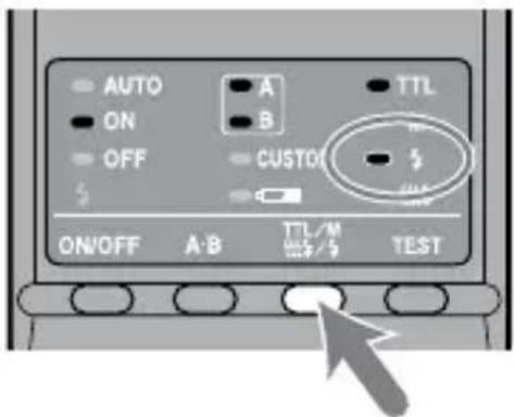
1 Press the TTL/M/Test button to turn on the test-flash lamp ♣.
Each time the TTL/M/Test button is pressed to change the TTL and M lamp be sure to check that the appropriate lamp is on. (See page 33 for the display sequence.)
2 Press the TEST button (test/modeling flash button).

- With TTL flash metering, the test flash will fire at full power when the TEST button is pressed.
- In manual flash mode, the test flash will fire at the selected power level when the TEST button is pressed. When using a flash meter, use manual flash mode.
Modeling flash
You can try continuous flash to check for shadows on the subject before shooting. The flash will fire for two seconds at a rate of 40 flashes per second.
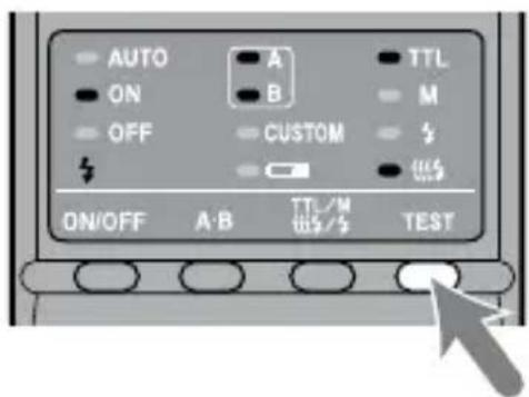
1 Press the TTL/M/Test button to turn on the modeling-flash lamp
Each time the TTL/M/Test button is pressed to change the TTL and M lamp be sure to check that the appropriate lamp is on. (See page 33 for the display sequence.)

2 Press the TEST button (test/modeling flash button).
- Do not press the shutter button while the flash is in use.
- The strength of shadows will differ from that during actual photography.
- When using the flash in a bright place or outdoors or when using a bounce flash, shadows are lighter so verification is more difficult.
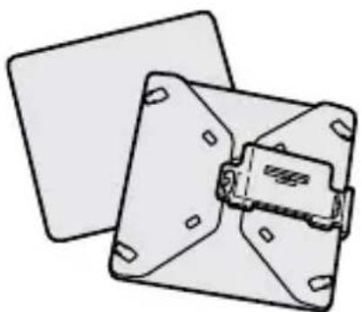
Wide panel
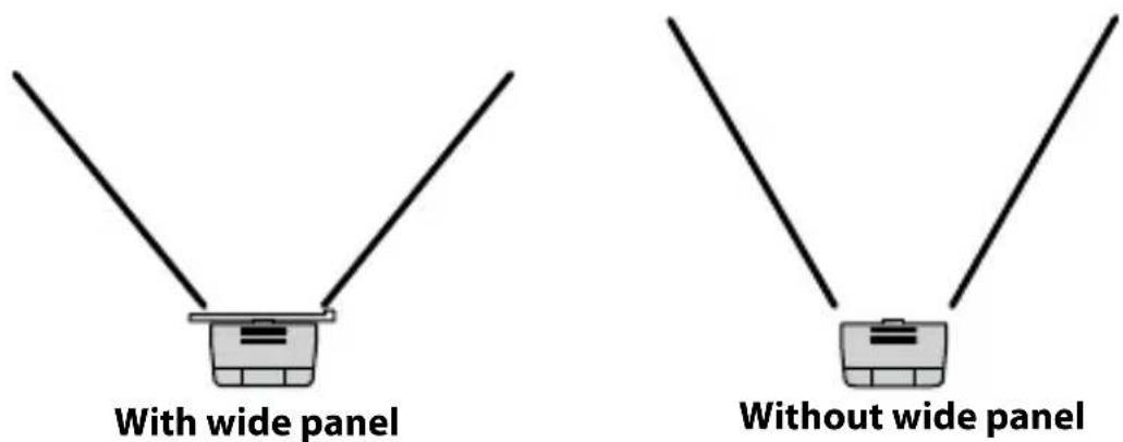
The twin flash unit has a coverage of 60^ horizontally and 45^ vertically (equivalent to a lens with a 35mm focal length). By attaching the wide panel, the angles are increased to 78^ horizontally and 60^ vertically (equivalent to a lens with a 24mm focal length).
Attaching the wide panel
1 Check the front side of the wide panel.

2 Align the lower edge of the wide panel to the projection on the side of the flashtube and press the wide panel.
Press the wide panel until it clicks into place.

natural_image
Two identical illustrations of a robotic arm with a keyboard and grid-patterned cover, showing mechanical components (no text or symbols)Removing the wide panel
Hold the top tab of the wide panel and remove it forwards while pressing downward slightly.

natural_image
Illustration of a mechanical component with a grid-patterned connector and cable (no text or symbols)The flash output is reduced when using the wide panel. See page 28 for TTL flash metering and page 38 for manual flash metering.
Diffuser
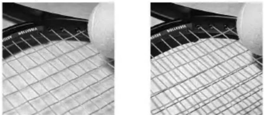
Strong shadows can be softened by attaching the diffuser to the flashtube. Always use the diffuser with an arm to prevent it appearing in the image.
Example:
natural_image
Close-up of two tennis netting grids showing meshing and surface texture (no text or symbols)With diffuser Without diffuser
Using the diffuser
1 Unclip the panel from the diffuser.
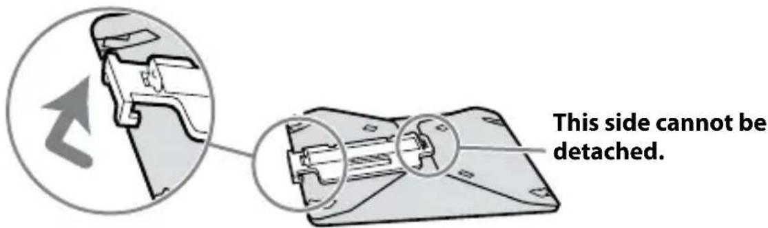
2 As illustration, slide the tab through the slot near the clip. The dimple above the slot should slide fit into the hole in the tab.

natural_image
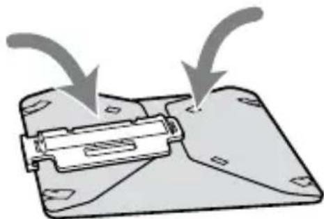
Diagram showing a vehicle interior with a lever mechanism before and after assembly (no text or symbols)3 Place the four side tabs into the slot on the side of the diffuser.
On the other side, in the same way, place the four side tabs into the slots.

natural_image
Diagram showing a device being processed from a base to a final component, with no visible text or symbols.- If it is difficult to assemble the diffuser, fold it up and try again.
natural_image
Diagram of a device with arrows indicating flow or movement, no text or symbols presentNote
Do not force or pull hard on the diffuser. Do not fold the diffuser inside out.
Continuedonthenextpage
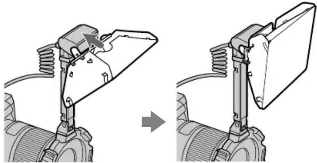
4 While holding the diffuser by its panel's top tab, press it against the face of the twin flash unit.
Press the diffuser until it clicks into place.
natural_image
Mechanical assembly diagram showing a lever mechanism before and after assembly (no text or symbols)Notes on using the diffuser
- If the arm is set at the 60^ position and used with a wide angle lens, the diffuser may appear in the image. It is recommended that you always use the diffuser with the arm set at the 90^ position.
- The flash output is reduced when using the diffuser. See page 28 for TTL flash metering, or page 38 for manual flash metering.
Removing the diffuser
1 Remove the diffuser while holding its panel's top tab.

natural_image
Mechanical assembly diagram showing a lever mechanism with no visible text or symbols2 Pull the tab off the dimple as illustration. The diffuser can now be easily removed.

natural_image
Diagram of a mechanical component with an arrow indicating force or movement, no visible text or symbols3 Refold the diffuser and secure it by clipping the panel to it.

natural_image
Diagram showing mechanical assembly with arrows indicating motion, no text or symbols presentCustom setting
The various flash settings can be changed as necessary.
The following three items may be changed.
- Time to auto power off (4 minutes/15 minutes/60 minutes/None)
- Recording modes in which manual flash may be set (M mode only/All modes)
- Manual-flash power-level steps (1EV increments / 1/2EV increments)
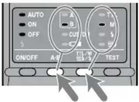
1 Press the flash ON/OFF button for three seconds.
The auto lamp, flash-ON lamp and flash-OFF lamp all come on together, and the item (time to auto power off) is displayed.

2 Press the A-B button (twin-flash A-B selection button) to select the item, and press the TTL/M/Test button to select the desired setting.
Each time the A-B button is pressed, the above three items appear on the control panel (see following page).
SelectusingtheTTL/M/Testbutton
1.Timetoautopoweroff

4minutes15minutes

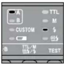
60minutesNone

2. Recording modes in which manual flash may be set

MmodeonlyAllmodes

3. Manual-flashpower-levelsteps

1EVincrements1/2EVincrements

Continuedonthenextpage
3 After making your selections, press the flash ON/OFF button to return to exit the custom mode.

- When a setting other than the default setting is selected in custom mode, the custom lamp on the control panel comes on.
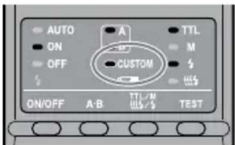
- When “All modes” is selected (see 2. Recording modes in which manual flash may be set), manual flash may be used in all recording modes.*
* The proper exposure may not be obtained in modes other than M mode. Using M mode is therefore recommended. - If “1/2 EV steps” is selected in item 3, use the gray power values provided on the lower scale of the manual-flash-control dials. The half-stop values are not written on the scale.
The power values are 1/1, 1/1.4, 1/2, 1/2.8, 1/4, 1/5.6, and 1/8. - The selected settings are maintained even when the flash unit is turned off or the battery removed.
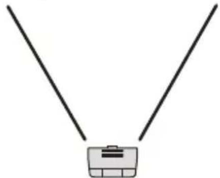
Examples of macro twin flash photography
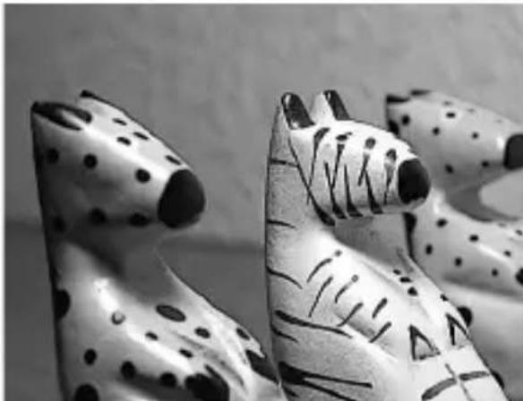
By using this macro twin flash, you can change the position and angle of the twin flash unit to achieve more expressive lighting.
Example:
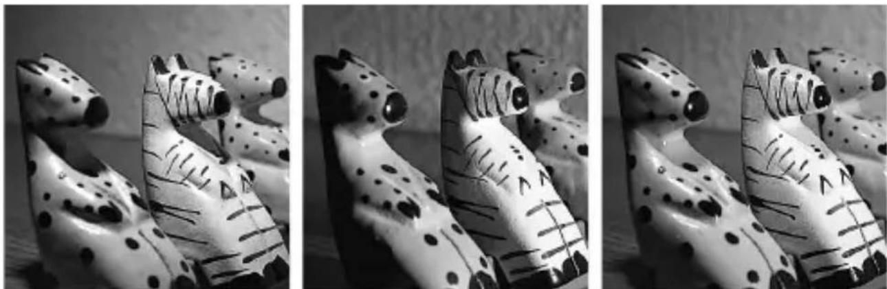
Top light only Side light only Top and side light
Strong shadows of the subjects can be softened by using the diffuser attached to the flashtube (p. 44).
Example:
natural_image
Black-and-white close-up of two patterned tiger figurines with black and white designs (no text or symbols)Top light with diffuser
Continuedonthenextpage
Two twin flash shooting with arms
To accent detail and give depth, illuminate the subject from the sides using the arms.
Example:
With arms from the sides

natural_image
Black-and-white close-up of white flowers with leaves against a dark background (no text or symbols)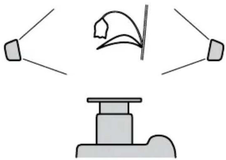
natural_image
Diagram showing three objects: a speaker emitting sound waves, a bird-like figure with curved lines, and a podium with a ladder (no text or symbols)Without arms from the front

natural_image
Black-and-white close-up of white flowers with stems and leaves, no text or symbols visible
natural_image
Simple line drawing of a mechanical device with a curved component above it (no text or symbols)Note
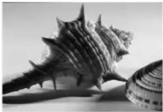
If a close-up subject is illuminated from the side using an arm, strong shadows may occur. Strong flash illumination from behind the subject can cause flaring.
- This condition is particularly likely to occur with a 50mm F2.8 Macro lens with flashtubes mounted on arms.
Example:
With arms from the sides
natural_image
Black-and-white photo of a seashell with spiky fronds and a circular shell (no text or symbols)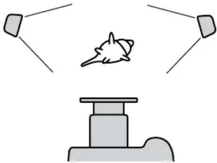
natural_image
Simple diagram showing a rocket launch with two targets and a base station (no text or symbols)Without arms from the front

natural_image
Black-and-white photo of a spiky seashell and a circular decorative object (no text or symbols visible)
natural_image
Simple line drawing of a mechanical device with a gear-like object above it (no text or symbols)Aperture range graph
The aperture range for macro lenses is displayed on page 26 (TTL), and page 34 (Manual flash). The aperture ranges described here are for lenses other than macro lenses, or when the subject distance is large.
TTL flash metering

line
| Flash-subject distance (m) | Aperture (F No.) | | -------------------------- | ---------------- | | 0.3 | 32 | | 0.3 | 22 | | 0.3 | 16 | | 0.3 | 8 | | 0.3 | 4 | | 0.3 | 2 | | 0.3 | 1 | | 0.3 | 0.5 | | 0.3 | 0.2 | | 0.3 | 0.1 | | 0.3 | 0.05 | | 0.3 | 0.02 | | 0.3 | 0.01 | | 0.3 | 0.005 | | 0.3 | 0.002 | | 0.3 | 0.001 | | 0.3 | 0.0005 | | 0.3 | 0.0002 | | 0.3 | 0.0001 | | 0.3 | 0.00005 | | 0.3 | 0.00002 | | 0.3 | 0.00001 | | 0.3 | 0.000005 | | 0.3 | 0.000002 | | 0.3 | 0.000001 | | 0.3 | 0.0000005 | | 0.3 | 0.0000002 | | 0.3 | 0.0000001 | | 0.3 | 0.00000005 | | 1 | 16 | | 1 | 8 | | 1 | 4 | | 1 | 2 | | 1 | 1 | | 1 | 0.5 | | 1 | 0.2 | | 1 | 0.1 | | 1 | 0.05 | | 1 | 0.02 | | 1 | 0.01 | | 1 | 0.005 | | 1 | 0.002 | | 1 | 0.001 | | 1 | 0.0005 | | 1 | 0.0002 | | 1 | 0.0001 | | 1 | 0.00005 | | 1 | 0.00002 | | 1 | 0.00001 | | 1 | 0.000005 | | 1 | 0.000002 | | 1 | 0.000001 | | 1 | 0.0000005 | | 1 | 0.0000002 | | 1 | 0.0000001 | | 1 | 0.00000005 | | 1 | 9 | | 1 | 6 | | 1 | 4 | | 1 | 2 | | 1 | 1 | | 1 | 1 | | 1 | 1 | | 1 | 1 | | 1 | 1 | | 1 | 1 | | 1 | 1 | | 1 | 1 | | 1 | 1 | | 1 | 1 | | 1 | 1 | | 1 | 15 | | 1 | 8 | | 1 | 4 | | 1 | 2 | | 1 | 1 | | 1 | 1 | | 1 | 1 | | 1 | 1 | | 1 | 1 | | 1 | 1 | | 1 | 1 | | 1 | 1 | | 1 | 15 | | 1 | 6 | | 1 | 2 | | 1 | 1 | | 1 | 1 | | 1 | 1 | | 1 | 1 | | 1 | 1 | | 1 | 1 | | 1 | 1 | | 1 | 1 | | 1 | 7 | | 1 | 2 | | 1 | -2 | | 7 | -4 | | 7 | -6 | | 7 | -8 | | 7 | -6 | | 7 | -4 | | 7 | -2 | | 7 | -1 | | 7 | -2 | | 7 | -4 | | 7 | -6 | | 7 | -8 | | 7 | -6 | | 7 | -4 | | 7 | -2 | | 7 | -1 | | 7 | -2 | | 7 | -4 | | 7 | -6 | | 7,8 | -8 | |8 | -6 | |8 | -4 | |8 | -2 | |8 | -1 | |8 | -2 | |8 | -4 | |8 | -6 | |8 | -8 | |8 | -6 | |8 | -4 | |8 | -2 | |8 | -2 | |8 | -2 | |8 | -4 | |8 | -6 | |8 | -8 | |8 | -6 | |8 | -8 | |8 | -4 | |8 | -2 | |8 | -2 | |8 | -2 | |8 | -4 | |8 | -6 | |8 | -8 | | 9 | -6 | |9 | -4 | |9 | -2 | |9 | -1 | |9 | -2 | |9 | -4 | |9 | -6 | |9 | -8 | |9 | -6 | |9 | -4 | |9 | -2 | |9 | -2 | |9 | -2 | |9 | -4 | |9 | -6 | | 9 | -8 | | 9 | -6 | | 9 | -4 | | 9 | -2 | | 9 | -2 | | 9 | -2 | | 9 | -4 | | 9 | -6 | | 9 | -8 | | 95 | -6 | |95 | -4 | |95 | -2 | |95 | -1 | |95 | -2 | |95 | -4 | |95 | -6 | |95 | -8 | | 95 | -6 | | 95 | -4 | | 95 | -2 | | 95 | -2 | | 95 | -2 | | 95 | -4 | | 95 | -6 | | 95 | -8 | The chart displays two horizontal lines labeled 'Min.Aperturelines' and 'Max.Aperturelines', each representing a minimum aperture line with a corresponding aperture value (F No.) for each aperture level (F No.) on the vertical axis.The following explains how to obtain the aperture range using the two twin flash units with a 1.5 m flash-to-subject distance and at ISO 100.
1 Draw a vertical line upwards from the flash-to-subject distance until it reaches the minimum aperture line (A).
2 Draw a horizontal line leftwards from Ⓐ until it reaches the vertical ISO line corresponding to the camera used (B).
3 Draw a diagonal line from Ⓑ upwards and leftwards. The result indicates the minimum aperture that will provide the proper exposure ( ⓒ ).
4 The maximum aperture can be obtained in the same way by using the maximum aperture line (D). The results of both calculations will give the usable aperture range for obtaining the proper exposure (E).
In this case, the proper exposure can be obtained by setting the camera's aperture from maximum to f/16.
- The dotted lines are employed when only one twin flash unit is used.
Manual flash metering
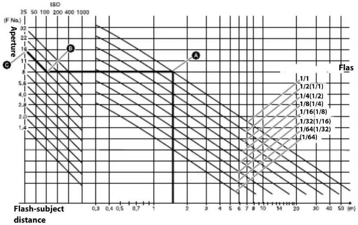
line
| Flas | Aperture (F No.) | | -------- | ---------------- | | 1/1 | 8 | | 1/2(1/1) | 8 | | 1/4(1/2) | 8 | | 1/8(1/4) | 8 | | 1/16(1/8)| 8 | | 1/32(1/16)| 8 | | 1/64(1/32)| 8 | | 1/64 | 8 |The following explains how to obtain the aperture using the two twin flash units with a power level of 1/1 at 1.5 ~m flash-to-subject distance and at ISO 100.
1 Draw a vertical line upwards from the flash-to-subject distance until it reaches the flash power line that corresponds to the set power level (A).
2 Draw a horizontal line leftwards from Ⓐ until it reaches the vertical ISO line corresponding to the camera used (B).
3 Draw a diagonal line from Ⓑ upwards and leftwards. The result indicates the aperture that will provide the proper exposure ( ⓒ ).
In this case, the proper exposure can be obtained by setting the camera's aperture to f/16.
- The figures in parenthesis are employed when only one twin flash unit is used.
Compatibility with other products
Lens
- 49 mm and 55 mm adaptor rings are supplied.
- Lenses whose barrels rotate when auto-focusing cannot be used.
- When a wide angle lens is used, part of the holder may appear in the image. Do not use lenses whose focal length is shorter than 24 mm. If the focal length is between 24 mm and 27 mm, contact an authorized Sony dealer.
- If using a filter at a focal length of less than 50 mm, part of the holder may appear in the image.
Notes on use
While shooting
- This flash unit generates strong light, so it should not be used directly in front of the eyes.
Batteries
- Do not store the macro flash controller with the alkaline batteries inside it. Leakage from the batteries may damage the battery chamber.
- Depending on the temperature or storage conditions, the battery level displayed may be lower than the actual battery capacity. The displayed battery level is restored to the correct value after the flash has been used a few times. When lamp blinks to indicate that the flash cannot be used, pressing the flash ON/OFF button a number of times may result in restoration of the correct battery level display. If the battery level is still not restored, replace the battery.
- When using lithium batteries, if the batteries become hot due to high temperature or continuous use, clamp may blink and the flash may not work for a while. Wait for the batteries to cool down before using the flash again.
- Nickel-metal hydride batteries can lose power suddenly. If clamp starts blinking or the flash can no longer be used while taking pictures, change or recharge the batteries.
- The flash frequency and number of flashes provided by new batteries may vary from the values shown in the table, depending on the time elapsed since manufacture of the batteries.
Continuedonthenextpage
Temperature
- The flash unit may be used over a temperature range of 0^ to 40^ .
- Do not expose the flash unit to extremely high temperatures (e.g. in direct sunlight inside a vehicle) or high humidity.
- To prevent condensation forming on the flash, place it in a sealed plastic bag when bringing it from a cold environment into a warm environment. Allow it to reach room temperature before removing it from the bag.
- Battery capacity decreases at colder temperatures. Keep your camera and spare batteries in a warm inside pocket when shooting in cold weather. □ lamp may light on even when there is some power left in the batteries in cold weather. Batteries will regain some of their capacity when warmed to normal operating temperature.
- This flash unit is not waterproof. Be careful not to bring it into contact with water or sand when using it at the seashore, for example. Contact with water, sand, dust, or salt may result in a malfunction.
Maintenance
Remove this unit from the camera. Clean the flash with a dry soft cloth. If the flash has been in contact with sand, wiping will damage the surface, and it should therefore be cleaned gently using a blower. In the event of stubborn stains, use a cloth lightly dampened with a mild detergent solution, and then wipe the unit clean with a dry soft cloth. Never use strong solvents, such as thinner or benzene, as these damage the surface finish.
Specifications
Guide number
Normal flash (ISO 100)
| Power level | 1 tube 2 tubes | Wide panel | Diffuser |
| 1/1 17 24 11 7 | |||
| 1/2 12 17 8 5 | |||
| 1/4 8.5 12 5.6 3.5 | |||
| 1/8 6 8.5 4 2.5 | |||
| 1/16 4.2 6 2.8 1.8 | |||
| 1/32 3 4.2 2 1.3 | |||
| 1/64 2.1 3 1.4 0.9 |
Wide panel and diffuser is for one tube.
Frequency/Repetition
| Alkaline Lithium | Nickel-hydride (1550 mAh) | |||
| Frequency (sec) 0.2~6 0.2~6 0.2~5 | ||||
| Repetition (times) 200~4000 500~10000 150~3000 | ||||
- Repetition is the approximate number of times that are possible before a new battery is completely dead.
Flash coverage
| Flash coverage | Twin flash | Wide panel | Diffuser |
| Vertical 45° | 60° | 90° | |
| Horizontal | 60° | 78° | 90° |
Continuous flash performance
40 flashes at 5 flashes per second
(Power level 1/32, nickel-metal hydride battery)
Flash control Flash control using pre-flash, TTL direct metering,
Manual flash
Dimension (Approx.)
Macro flash controller
68 × 123 × 91 ~mm (2 3/4 × 47/8 × 35/8 in.) (w × h × d)
Twin flash unit
43 × 41 × 37 ~mm (1 3/4 × 15/8 × 11/2 in.) (w × h × d)
Mass (Approx.) Macro flash controller 235 g (8.3 oz.) (without batteries)
Twin flash unit 33 g (1.2 oz.) (per twin flash unit)
Operating temperature
0^ to 40^ (32°F to 104°F)
Included items Macro flash controller (1), Twin flash unit (2), Holder (1),
Arm (2), Adaptor ring 49mm (1),
Adaptor ring 55mm (1), Wide panel (2), Diffuser (2),
Cord reel (2), Controller case (1), Flash case (1),
Set of printed documentation
Functions in these operating instructions depend on testing conditions at our firm.
Design and specifications are subject to change without notice.
Trademark
α is a trademark of Sony Corporation.
Français
natural_image
Symbol of a trash bin crossed with no text or numbers, representing waste sorting or disposal (no text present)Bagues adaptatrice (13) ø 49 mm, ø 55 mm

natural_image
Illustration of two overlapping rings (no text or symbols)natural_image
Technical line drawing of a mechanical component with mounting holes and internal structure (no text or symbols)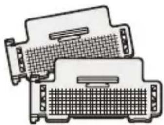
natural_image
Illustration of two computer monitors with ventilation grilles (no text or symbols)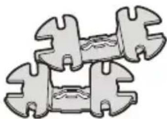
natural_image
Illustration of a mechanical clamp or clamping device with interlocking brackets (no text or symbols)* Deux fournis
Exemple de stockage

Insertion des piles
natural_image
Illustration of a camera module with four batteries and a battery cover (no text or symbols)3 Refermez le compartiment.
Témoin allamé
natural_image
Illustration of a DSLR camera with an LCD screen and adjustment knob (no text or symbols)natural_image
Line drawing of a DSLR camera with lens and aperture (no text or symbols)natural_image
Technical illustration of a mechanical component with gear and adjustment arrows (no text or symbols)natural_image
Line drawing of a portable device with two buttons and a close button, no text or symbols presentnatural_image
Mechanical assembly diagram showing a tractor with gear and valve mechanism (no text or symbols)natural_image
Illustration of a portable electronic device with ports and an attached plug (no text or symbols)natural_image
Technical line drawing of a mechanical device with adjustment knobs and a directional arrow (no text or symbols)natural_image
Diagram of a mechanical device with directional arrows indicating rotation or movement (no text or symbols)natural_image
Technical diagram of a mechanical component with three arms and directional arrows indicating flow or movement (no text or symbols)natural_image
Mechanical assembly diagram showing a lever interacting with a gear (no text or symbols visible)natural_image
Technical line drawing of a mechanical device with lever and clamping mechanism (no text or symbols)natural_image
Technical illustration of mechanical components with angular annotations (60° and 90°), no readable text or symbols present.natural_image
Mechanical component diagram showing a lever mechanism with adjustment arrows (no text or symbols)natural_image
Mechanical component with coiled spring and plug assembly, showing magnified detail (no text or symbols)natural_image
Mechanical assembly diagram showing a mechanical component with bolts and a directional arrow indicating motion (no text or symbols)natural_image
Technical line drawing of a mechanical assembly with hoses and components (no text or symbols)natural_image
Mechanical assembly diagram showing a robotic arm with attached spring and connecting rod (no text or symbols)tree
| Position | Diaphragme | Demi diaphragme | |---|---|---| | 1 | 180 | 152 | | 2 | 128 | 108 | | 3 | 90 | 76 | | 4 | 64 | 54 | | 5 | 45 | 38 | | 6 | 32 | 27 | | 7 | 22 | 19 | | 8 | 16 | 13 | | 9 | 11 | 9.5 | | 10 | 8 | 6.7 | | 11 | | | | 12 | 5.6 | 4.5 | | 13 | | | | 14 | 4 | 3.5 | | 15 | 2.8 | 2.4 | | 16 | | | | 17 | 2 | 1.7 | | 18 | 1.4 | 1.2 | | 19 | | | | 20 | 1 | 0.85 | The diagram illustrates a hierarchical relationship between diaphragme and demi diaphragme, with 'Réduit l'exposition' indicating the relative role of these two expositions.natural_image
Simple line drawing of a container with two vertical rods extending upward (no text or symbols)natural_image
Simple line drawing of a box with two vertical lines above it, no text or symbols present.natural_image
Illustration of a robot arm holding a laptop, with no visible text or symbols
natural_image
Illustration of a mechanical device with a grid-patterned panel attached (no text or symbols visible)natural_image
Illustration of a mechanical device with a grid-patterned panel attached to its side (no text or symbols visible)natural_image
Diagram showing a car interior with a steering wheel and directional arrows, before and after assembly (no text or symbols)natural_image
Diagram showing a device being processed from a base to a final component, with no visible text or symbols.natural_image
Diagram of a mechanical component with arrows indicating direction (no text or symbols)Remarque
natural_image
Mechanical assembly diagram showing a lever mechanism before and after assembly (no text or symbols)natural_image
Mechanical assembly diagram showing a lever mechanism with no visible text or symbolsnatural_image
Diagram of a mechanical component with an arrow indicating direction, no visible text or symbolsnatural_image
Diagram showing mechanical assembly with arrows indicating motion (no text or symbols)natural_image
Black-and-white photo of three patterned tiger-themed objects with black and white stripes (no text or symbols visible)natural_image
Black-and-white photo of two stylized animal figurines with spotted patterns and large eyes (no text or symbols)natural_image
Black-and-white photo of three patterned ceramic figurines with black and white designs (no text or symbols)natural_image
Black-and-white close-up of two patterned tiger figurines with dot patterns, no text or symbols visiblenatural_image
Black-and-white close-up of three white flowers with stems and leaves against a dark background (no text or symbols)
natural_image
Diagram showing three light sources projecting a car silhouette, with a base platform below (no text or symbols)natural_image
Black-and-white close-up of white flowers with stems and leaves, no text or symbols visible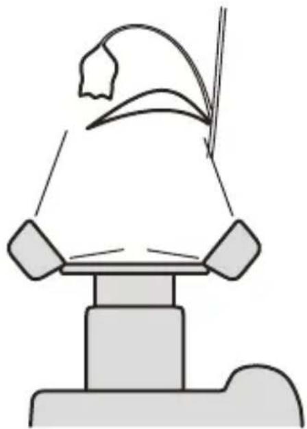
natural_image
Simple line drawing of a mechanical device with a curved component above it (no text or symbols)natural_image
Black-and-white artistic photo of a seashell with spiky fronds and a circular object partially visible (no text or symbols)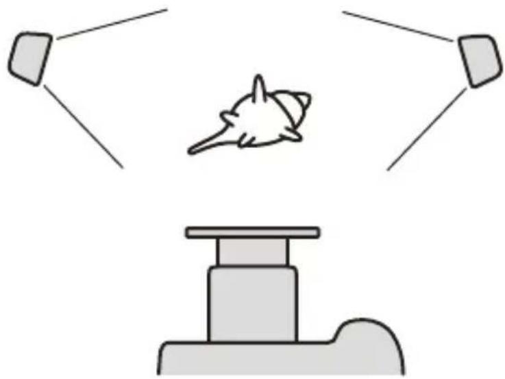
natural_image
Diagram showing a rocket launch with two radar beams and a base station (no text or symbols)natural_image
Black-and-white photo of a seashell with spiky shell and a circular decorative object beside it (no text or symbols visible)
natural_image
Simple line drawing of a mechanical device with a suspended object above it (no text or symbols)natural_image
Symbol of a trash bin crossed with no text or numbers, representing waste sorting or disposal (no text present)natural_image
Illustration of two overlapping rings (no text or symbols)Softbox* (43)
natural_image
Technical line drawing of a mechanical component with mounting holes and internal structure (no text or symbols)natural_image
Illustration of two computer monitors with ventilation grilles (no text or symbols)natural_image
Illustration of a mechanical clamp or wrench with no text or symbols* Zwei mitgeliefert
natural_image
Diagram of a camera module with three batteries and a display panel (no text or symbols)natural_image
Illustration of a DSLR camera with an attached display screen and mechanical components (no text or symbols)natural_image
Line drawing of a DSLR camera with lens and aperture (no text or symbols)natural_image
Technical illustration of a mechanical component with gear and mounting holes (no text or symbols)natural_image
Illustration of a portable device with a button and handle, no text or symbols presentnatural_image
Mechanical assembly diagram showing a tractor with attached gear and a belt drive (no text or symbols)natural_image
Illustration of a camera device with two ports and an attached plug, showing no text or symbols.natural_image
Technical line drawing of a mechanical device with adjustment knobs and a directional arrow (no text or symbols)natural_image
Diagram of a mechanical device with directional arrows indicating rotation or movement (no text or symbols)natural_image
Top-down schematic of a mechanical component with three arms and central hub (no text or symbols)natural_image
Mechanical assembly diagram showing a lever interacting with a cam or tire component (no text or symbols visible)natural_image
Technical line drawing of a mechanical device with lever and connecting rod (no text or symbols)natural_image
Technical illustration of two mechanical assembly steps showing a lever mechanism (no text or symbols present)60°-Position 90°-Position
natural_image
Technical illustration of a mechanical device with adjustment knobs and connectors (no text or symbols)natural_image
Close-up of a car electrical plug with coiled cable and socket, showing wiring details (no text or symbols)natural_image
Mechanical assembly diagram showing a mechanical component with rotating parts and a directional arrow indicating motion (no text or symbols present)natural_image
Technical line drawing of a mechanical assembly with hoses and components (no text or symbols)natural_image
Technical line drawing of a mechanical assembly with a spring and linkage (no text or symbols)natural_image
Illustration of a mechanical device with a grid-patterned cover and cable, no visible text or symbolsnatural_image
Diagram showing a car interior with a steering wheel and directional arrows, before and after assembly (no text or symbols)natural_image
Diagram showing a device being processed from a base to a final component, with no visible text or symbols.natural_image
Diagram of a mechanical component with arrows indicating direction (no text or symbols)Hinweis
natural_image
Mechanical assembly diagram showing a lever mechanism before and after assembly (no text or symbols)natural_image
Mechanical assembly diagram showing a lever mechanism with no visible text or symbolsnatural_image
Diagram of a mechanical component with an arrow indicating force or movement, no visible text or symbolsnatural_image
Diagram showing mechanical assembly with arrows indicating direction of movement (no text or symbols present)natural_image
Black-and-white photo of four ceramic tiger-shaped figurines with black-and-white patterns, arranged in a row (no text or symbols visible)natural_image
Black-and-white close-up of two patterned tiger figurines with dot patterns, no text or symbols visiblenatural_image
Black-and-white close-up of white flowers with green leaves against a dark background (no text or symbols)
natural_image
Simple line drawing of two endpoints with a curved arrow and a small figure inside, no text or symbols present.
natural_image
Simple line drawing of a mechanical component or tool (no text or symbols)natural_image
Black-and-white close-up of white, flower-like structures with stems and leaves against a dark background (no text or symbols)
natural_image
Simple line drawing of a mechanical device with a curved component above it (no text or symbols)natural_image
Black-and-white artistic photo of a seashell with spiky fronds and a circular object partially visible (no text or symbols)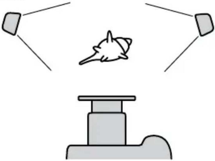
natural_image
Simple diagram showing a rocket launch with two targets and a base station (no text or symbols)natural_image
Black-and-white photo of a seashell with spiky shell and a circular decorative object beside it (no text or symbols visible)
natural_image
Simple line drawing of a mechanical device with a suspended object above it (no text or symbols)natural_image
Simple line drawing of a trash bin with two crossed lines indicating no waste or restriction (no text or symbols)
natural_image
Illustration of two overlapping rings (no text or symbols)natural_image
Technical line drawing of a mechanical component with mounting holes and internal structure (no text or symbols)
natural_image
Illustration of two computer heat exchangers with mesh insulation (no text or symbols)natural_image
Illustration of a mechanical clamp or spring with two interlocking parts (no text or symbols)* Due in dotazione

natural_image
Illustration of a camera module with four batteries and a display panel (no text or symbols)natural_image
Diagram of a DSLR camera with an attached display and control panel, showing no text or symbols.natural_image
Line drawing of a DSLR camera with lens and aperture (no text or symbols)natural_image
Technical illustration of a mechanical component with gear and adjustment arrows (no text or symbols)natural_image
Line drawing of a portable device with buttons and a close button, no text or symbols presentnatural_image
Mechanical assembly diagram showing a belt drive mechanism with no visible text or symbolsnatural_image
Line drawing of a portable device with ports and connectors, showing a cable inserted (no text or symbols)natural_image
Technical line drawing of a mechanical device with adjustment knobs and a directional arrow (no text or symbols)natural_image
Diagram of a mechanical device with directional arrows indicating rotation or movement (no text or symbols)natural_image
Technical diagram of a mechanical component with three arms and directional arrows indicating flow or movement (no text or symbols)natural_image
Mechanical assembly diagram showing a robotic arm interacting with a gear (no text or symbols visible)natural_image
Technical line drawing of a mechanical device with lever and connecting rod (no text or symbols)natural_image
Technical illustration of mechanical components with no visible text or symbolsnatural_image
Technical illustration of a mechanical device with no visible text or symbolsnatural_image
Mechanical diagram showing a plug inserted into a wire with a magnified inset highlighting the cable detail (no text or symbols present)natural_image
Mechanical assembly diagram showing a gear mechanism with no visible text or symbolsnatural_image
Technical line drawing of a mechanical assembly with hoses and connectors (no text or symbols)natural_image
Technical line drawing of a mechanical assembly with a spring and linkage (no text or symbols)tree
| Node | Value | |---|---| | 1 | 0.85 | | 2 | 1.7 | | 3 | 1.4 | | 4 | 3.5 | | 5 | 4.5 | | 6 | 6.7 | | 7 | 9.5 | | 8 | 1 | | 9 | 13 | | 10 | 16 | | 11 | 19 | | 12 | 22 | | 13 | 27 | | 14 | 32 | | 15 | 38 | | 16 | 45 | | 17 | 54 | | 18 | 64 | | 19 | 76 | | 20 | 90 | | 21 | 108 | | 22 | 128 | | 23 | 152 | | 24 | mezzo stop (top node) | | 25 | complete (top node) | The diagram shows a hierarchical decomposition with vertical arrows indicating the decomposition process.natural_image
Simple line drawing of a V-shaped object with two diagonal lines extending upward from its base (no text or symbols)Con pannello ampio
natural_image
Simple line drawing of a box with two vertical lines above it, no text or symbols present.natural_image
Technical line drawing of a mechanical component with a grid-patterned base and mounting bracket (no text or symbols)Parte anteriore
natural_image
Illustration of a robotic arm holding a keyboard, with no visible text or symbols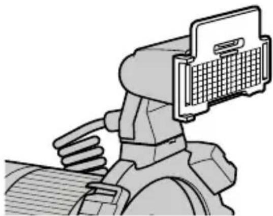
natural_image
Illustration of a mechanical component with a grid-like structure attached to its top (no text or symbols visible)natural_image
Illustration of a mechanical device with a grid-patterned connector and cable (no text or symbols)natural_image
Diagram showing a car interior with a handle and seat, before and after assembly (no text or symbols)natural_image
Diagram showing a device being processed from a base to a final component, with no visible text or symbols.natural_image
Diagram of a mechanical component with arrows indicating direction (no text or symbols)Nota
natural_image
Mechanical assembly diagram showing a lever mechanism before and after assembly (no text or symbols)natural_image
Mechanical assembly diagram showing a lever mechanism with no visible text or symbolsnatural_image
Diagram of a mechanical component with an arrow indicating direction, showing a cut or assembly (no text or symbols present)natural_image
Diagram showing mechanical assembly with arrows indicating motion (no text or symbols)natural_image
Black-and-white photo of two patterned tiger feet with black spots and striped designs (no text or symbols)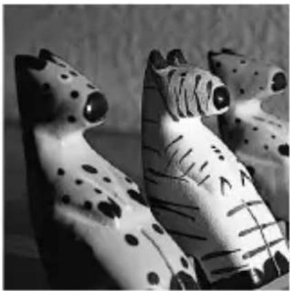
natural_image
Black-and-white photo of two stylized animal figurines with black spots and striped patterns (no text or symbols)
natural_image
Black-and-white photo of three patterned tiger figurines with black and white designs (no text or symbols)natural_image
Black-and-white close-up of two patterned tiger figurines with black and white designs (no text or symbols)natural_image
Black-and-white close-up of three white flowers with stems and leaves against a dark background (no text or symbols)
natural_image
Diagram showing three light sources projecting a curved object onto a platform, with no text or symbols present.natural_image
Black-and-white close-up of white flowers with green leaves, no text or symbols visible
natural_image
Simple line drawing of a mechanical device with a curved component above it (no text or symbols)natural_image
Black-and-white artistic photo of a seashell with spiky fronds and a circular object partially visible (no text or symbols)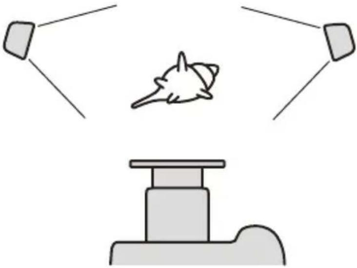
natural_image
Simple diagram showing a rocket with two ground stations above it and a base station below (no text or symbols)natural_image
Black-and-white photo of a seashell with spiky shell and a circular decorative object beside it (no text or symbols visible)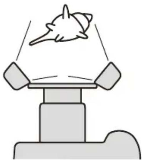
natural_image
Simple line drawing of a mechanical device with a gear-like object above it (no text or symbols)natural_image
Simple line drawing of a trash bin with two crossed lines indicating no waste or restriction (no text or symbols)
Adapterring (13)
ø49mm, ø55mm

natural_image
Illustration of two interlocking rings (no text or symbols)Diffuser* (43) Groothoekadapter*
(41)
natural_image
Technical illustration of a mechanical component with mounting holes and internal structure (no text or symbols)
natural_image
Illustration of three electronic components with no visible text or symbolsSnoerhaspel* (17)

natural_image
Illustration of a mechanical clamp or wrench with no text or symbols* Twee bijgeleverd

natural_image
Illustration of a camera module with four batteries and a top-mounted control panel (no text or symbols)natural_image
Diagram of a DSLR camera with an attached display screen and control buttons (no text or symbols)De macroduoflitser bevestigen
natural_image
Line drawing of a DSLR camera with a circular lens and arrow indicating rotation (no text or symbols)natural_image
Technical illustration of a mechanical component with gear and adjustment arrows (no text or symbols)natural_image
Illustration of a vintage camera with adjustment knobs and a button, no text or symbols presentnatural_image
Mechanical assembly diagram showing a lever pressing down on a tractor wheel (no text or symbols visible)natural_image
Illustration of a camera device with ports and an external plug, no text or symbols presentnatural_image
Technical line drawing of a mechanical device with adjustment knobs and a directional arrow (no text or symbols)natural_image
Mechanical device with rotating arrow indicating rotation (no text or symbols)natural_image
Top-down schematic of a mechanical component with three arms and central hub (no text or symbols)natural_image
Mechanical assembly diagram showing a lever interacting with a cam or tire component (no text or symbols visible)natural_image
Technical line drawing of a mechanical device with lever and connecting rod (no text or symbols)natural_image
Technical illustration of two mechanical components with no visible text or symbolsnatural_image
Illustration of a mechanical device with a wrench inserted into a housing (no text or symbols visible)natural_image
Close-up of a car electrical plug with coiled cable and socket, showing mechanical assembly (no text or symbols)natural_image
Mechanical component diagram showing a rotating mechanism with arrows indicating motion (no text or symbols)natural_image
Technical line drawing of a mechanical assembly with hoses and components (no text or symbols)natural_image
Technical line drawing of a mechanical assembly with a spring and linkage (no text or symbols)tree
| Node | Value | |---|---| | 1 | 180 | | 2 | 152 | | 3 | 128 | | 4 | 108 | | 5 | 90 | | 6 | 76 | | 7 | 64 | | 8 | 54 | | 9 | 45 | | 10 | 38 | | 11 | 32 | | 12 | 27 | | 13 | 22 | | 14 | 19 | | 15 | 16 | | 16 | 13 | | 17 | 9.5 | | 18 | 8 | | 19 | 6.7 | | 20 | 5.6 | | 21 | 4.5 | | 22 | 4 | | 23 | 3.5 | | 24 | 2.8 | | 25 | 2.4 | | 26 | 2 | | 27 | 1.7 | | 28 | 1.4 | | 29 | 1.2 | The image is a hierarchical tree diagram showing the structure of 'een halve stop' and 'Minder belichting Meer belichting'. The structure is divided into two branches: one for 'een hele stop' (left) and another for 'een halve stop' (right). The branches are labeled with their respective values.natural_image
Simple line drawing of a V-shaped container with two diagonal lines extending upward (no text or symbols)natural_image
Simple diagram of a V-shaped object with two long lines extending upward from its base (no text or symbols)Zonder groothoekadapter
De groothoekadapter bevestigen
natural_image
Two identical illustrations of a robotic arm with a keyboard inserted, showing the mechanism (no text or symbols present)natural_image
Illustration of a mechanical device with a grid-patterned cover and cable, no visible text or symbolsnatural_image
Close-up of tennis serve netting and surface meshing (no text or symbols visible)Met diffuser Zonder diffuser
natural_image
Diagram showing a car interior with a steering wheel and directional arrows, before and after assembly (no text or symbols)natural_image
Diagram showing a device being processed from a base to a final component, with no visible text or symbols.natural_image
Diagram of a mechanical component with arrows indicating direction (no text or symbols)Opmerking
natural_image
Mechanical assembly diagram showing a lever mechanism before and after assembly (no text or symbols)natural_image
Mechanical assembly diagram showing a lever mechanism with no visible text or symbolsnatural_image
Diagram of a mechanical component with an arrow indicating force or movement, no visible text or symbolsnatural_image
Diagram showing mechanical assembly with arrows indicating direction of movement (no text or symbols present)natural_image
Black-and-white photo of two patterned tiger-themed shoes with black and white stripes (no text or symbols visible)
natural_image
Black-and-white photo of two stylized animal figurines with black-and-white patterns and dot accents (no text or symbols)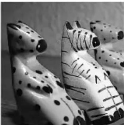
natural_image
Black-and-white photo of two patterned tiger figurines with black spots, no text or symbols visiblenatural_image
Black-and-white close-up of two patterned tiger figurines with black and white designs (no text or symbols)natural_image
Black-and-white close-up of three white flowers with stems and leaves against a black background (no text or symbols)
natural_image
Diagram showing three light sources projecting a curved object onto a platform, with no text or symbols present.natural_image
Black-and-white close-up of three white flower buds with stems and leaves, no text or symbols visible
natural_image
Simple line drawing of a mechanical device with a curved component above it (no text or symbols)natural_image
Black-and-white artistic photo of a seashell with spiky fronds and a circular object partially visible (no text or symbols)
natural_image
Simple diagram showing a rocket launch with two radar units and a base station (no text or symbols)natural_image
Black-and-white photo of a seashell with spiky shell and a circular decorative object beside it (no visible text or symbols)
natural_image
Simple line drawing of a mechanical device with a suspended object above it (no text or symbols)Grafiek diafragmabereik
line
| Afstand flitser-onderwerp (m) | I/O (F No.) | Region | |---|---|---| | 0.3 | 15 | C | | 0.3 | 8 | E | | 0.3 | 1.4 | D | | 0.3 | 2.8 | E | | 0.3 | 4.0 | E | | 0.3 | 5.6 | E | | 0.3 | 7.0 | E | | 0.3 | 8.4 | E | | 0.3 | 9.8 | E | | 0.3 | 11.2 | E | | 0.3 | 12.6 | E | | 0.3 | 14.0 | E | | 0.3 | 15.4 | E | | 0.3 | 16.8 | E | | 0.3 | 18.2 | E | | 0.3 | 19.6 | E | | 0.3 | 21.0 | E | | 0.3 | 22.4 | E | | 0.3 | 23.8 | E | | 0.3 | 25.2 | E | | 0.3 | 26.6 | E | | 0.3 | 28.0 | E | | 0.3 | 29.4 | E | | 0.3 | 30.8 | E | | 0.3 | 32.2 | E | | 0.3 | 33.6 | E | | 0.3 | 35.0 | E | | 0.3 | 36.4 | E | | 0.3 | 37.8 | E | | 0.3 | 39.2 | E | | 0.3 | 40.6 | E | | 0.3 | 42.0 | E | | 0.3 | 43.4 | E | | 0.3 | 44.8 | E | | 0.3 | 46.2 | E | | 0.3 | 47.6 | E | | 0.3 | 49.0 | E | | 0.3 | 50.4 | E | | 0.3 | 51.8 | E | | 0.3 | 53.2 | E | | 0.3 | 54.6 | E | | 0.3 | 56.0 | E | | 0.3 | 57.4 | E | | 0.3 | 58.8 | E | | 0.3 | 60.2 | E | | 0.3 | 61.6 | E | | 0.3 | 63.0 | E | | 0.3 | 64.4 | E | | 0.3 | 65.8 | E | | 0.3 | 67.2 | E | | 0.3 | 68.6 | E | | 0.3 | 70.0 | E | | 0.3 | 71.4 | E | | 0.3 | 72.8 | E | | 0.3 | 74.2 | E | | 0.3 | 75.6 | E | | 0.3 | 77.0 | E | | 0.3 | 78.4 | E | | 0.3 | 79.8 | E | | 0.3 | 81.2 | E | | 0.3 | 82.6 | E | | 0.3 | 84.0 | E | | 0.3 | 85.4 | E | | 0.3 | 86.8 | E | | 0.3 | 88.2 | E | | 0.3 | 89.6 | E | | 0.3 | 91.0 | E | | 0.3 | 92.4 | E | | 0.3 | 93.8 | E | | 0.3 | 95.2 | E | | 0.3 | 96.6 | E | | 0.3 | 98.0 | E | | 0.3 | 99.4 | E | | 0.3 | 100.8 | E | | 1 | - | A | | - | - | B | | - | - | D | | - | - | D | | - | - | D | | - | - | D | | - | - | D | | - | - | D | | - | - | D | | - | - | D | | - | - | D | | - | - | D | | - | - | A | | - | - | B | | - | - | D | | - | - | D | | - | - | D | | - | - | D | | - | - | D | | - | - | D | | - | - | D | | - | - | D | | - | - | A | | - | - | B | | - | - | D | | - | - | D | | - | - | D | | - | - | D | | - | - | D | | - | - | D | | - | - | D | | - | - | D | | - | - | D | | - | - | D | | - | - | A | | - | - | B | | - | - | D | | - | - | D | | - | - | D | | - | - | D | | - | - | D | | - | - | D | | - | - | D | | -```

- English
- WARNING
- IMPORTANT SAFETY INSTRUCTIONS
- SAVE THESE INSTRUCTIONS
- CAUTION
- For customers in Europe
- Disposal of Old Electrical & Electronic Equipment (Applicable in the European Union and other European countries with separate collection systems)
- < Notice for the customers in the countries applying EU Directives >
- For the customers in the U.S.A.
- NOTE:
- Table of contents
- Preparations
- Basics
- Detailed operations
- Additional Information
- Before use
- This flash is not dust-proof, splash-proof or waterproof.
- Do not place this flash in the following locations
- Features
- Name of parts
- Control Panel
- Macro Twin Flash
- Example of storage
- Inserting batteries
- Checking Batteries
- lamp on
- Only tap blinking
- Attachment and removal of the macro flash controller
- Attaching the macro flash controller to the camera
- Removing the macro flash controller from the camera
- Attaching the macro twin flash
- Screw the appropriate adaptor ring clockwise onto the lens.
- While pressing the tabs on each side of the holder, place the holder over the adaptor, and then release both tabs.
- Remove the protective socket caps of the macro flash controller.
- Place the twin flash unit into the shoe of one of the holders.
- Insert the plug of the twin flash unit into the twin-flash-cord socket on the macro flash controller.
- When removing the plug, press the twin flash-cord release button on the macro flash controller and pull the plug straight out of the socket.
- Adjust positions of the flashtubes as desired.
- Attaching the arm
- When changing the angle to 60° position, hold both ends of the arm and move it so that it clicks twice into place.
- Using the cord reel
- Attaching the cord reel to the macro flash controller
- Example of taking up the connecting cord
- Removing the cord reel
- Auto power ON/OFF
- Press the flash ON/OFF button on the back of the macro flash controller.
- Auto power off
- Basic flash modes (A mode/M mode)
- Select the flash.
- When the macro flash controller is charged, press the shutter button to take a photo.
- Selecting Apertures in TTL Flash
- Example: Using a 50mm F2.8 Macro lens when ISO 100, with a pair of twin flash units with no arm, at a magnification ratio of 1:1
- When using other than ISO 100, or when using the wide panel or diffuser
- f/stop scale
- Using the f/stop scale
- Example:
- Selecting the aperture when using other than ISO 100, or when using the wide panel or diffuser
- Example: Using a 50mm F2.8 Macro lens, two twin flash units, no arm, magnification ratio of 1:2, and ISO 200
- Program auto flash (The basics)
- Manual flash (M)
- Select M mode on the camera.
- Press the TTL/M/Test button to light on the M (manual-flash control) lamp.
- Selecting apertures and power level in manual flash
- Example: Using a 50mm F2.8 Macro lens when ISO 100, with a pair of twin flash units with no arm, power level of 1/1, and a magnification ratio of 1:1
- When twin flash units are at different power level settings
- Example: Using a 100mm F2.8 Macro lens, two twin flash units, no arm, a power level of 1/4, magnification ratio of 1:1, ISO 200 with the diffuser
- Test flash
- Press the TTL/M/Test button to turn on the test-flash lamp ♣.
- Press the TEST button (test/modeling flash button).
- Modeling flash
- Press the TTL/M/Test button to turn on the modeling-flash lamp
- Wide panel
- Attaching the wide panel
- Removing the wide panel
- Diffuser
- Using the diffuser
- Unclip the panel from the diffuser.
- Note
- While holding the diffuser by its panel's top tab, press it against the face of the twin flash unit.
- Notes on using the diffuser
- Removing the diffuser
- Custom setting
- Press the flash ON/OFF button for three seconds.
- Press the A-B button (twin-flash A-B selection button) to select the item, and press the TTL/M/Test button to select the desired setting.
- SelectusingtheTTL/M/Testbutton
- 1.Timetoautopoweroff
- Recording modes in which manual flash may be set
- Manual-flashpower-levelsteps
- After making your selections, press the flash ON/OFF button to return to exit the custom mode.
- Examples of macro twin flash photography
- Two twin flash shooting with arms
- Aperture range graph
- TTL flash metering
- Manual flash metering
- Compatibility with other products
- Lens
- Notes on use
- While shooting
- Batteries
- Temperature
- Maintenance
- Specifications
- Trademark
- Français
- Exemple de stockage
- Insertion des piles
- Témoin allamé
- Remarque
- Hinweis
- Nota
- De macroduoflitser bevestigen
- De groothoekadapter bevestigen
- Opmerking
- Grafiek diafragmabereik
Brand : SONY
Model : HVL-MT24AM
Category : Flash