
TPF 7000 S - Pump METABO - Free user manual and instructions
Find the device manual for free TPF 7000 S METABO in PDF.
| Brand | Metabo |
| Model | TPF 7000 S |
| Product type | Submersible pump for clear and dirty water |
| Application areas | Domestic and garden drainage, irrigation, pumping from containers, basins, swimming pools, drainage wells, flooded rooms |
| Float switch | Yes, with adjustable on/off level |
| Pressure connection | With angular connector and multiple adapter |
| Air vent | Yes, depending on model |
| Maximum liquid temperature | 35 °C |
| Required electrical protection | Residual current device (RCD) 30 mA max. |
| Power supply | 230 V ~ 50 Hz (typical mains voltage) |
| Maximum immersion depth | Up to the depth indicated in the technical specifications (not specified in the manual) |
| Maximum discharge head | See technical specifications (not specified in the manual) |
| Flat suction | Possible on TPF models (brief moment, monitoring required) |
| Regular maintenance | Rinse with clean water, clean the impeller by removing the base plate |
| Storage | Frost-free, drain residual water |
| Safety | Do not use with people in the water, do not pump flammable or aggressive liquids, disconnect before maintenance |
| Repairs | Entrust only to a qualified electrician or Metabo after-sales service |
| Disposal | Do not dispose of with household waste, recycle at a waste disposal facility |
| Included documentation | Original user manual (FR, DE, EN, etc.), keep for future use |
Frequently Asked Questions - TPF 7000 S METABO
User questions about TPF 7000 S METABO
0 question about this device. Answer the ones you know or ask your own.
Ask a new question about this device
Download the instructions for your Pump in PDF format for free! Find your manual TPF 7000 S - METABO and take your electronic device back in hand. On this page are published all the documents necessary for the use of your device. TPF 7000 S by METABO.
USER MANUAL TPF 7000 S METABO
natural_image
Technical line drawing of a mechanical device with tubing and a valve (no text or symbols)
ENG Original operating instructions....10
KONFORMITÄTSERKLÄRUNGVDECLARATION OF CONFORMITY
We herewith declare in our sole responsibility that this product complies with the following standards* in accordance with the regulations of the undermentioned Directives**
Director Innovation, Research and Development
Dokumentationsbevollmächtigter/ responsible person for documentation/ Chargé de la documentation
Metabowerke GmbH
Metabo-Allee 1
D - 72622 Nürtingen

natural_image
Technical line drawing of a mechanical device with no visible text or symbolsD DEUTSCH
natural_image
Line drawing of a car interior with hoses and a connector (no text or symbols)
natural_image
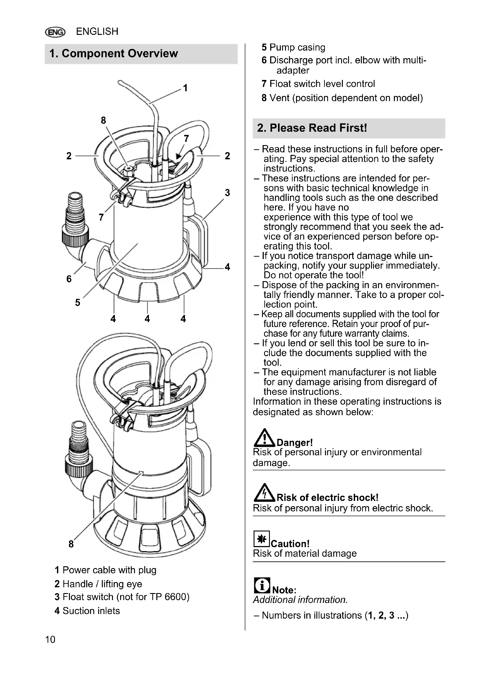
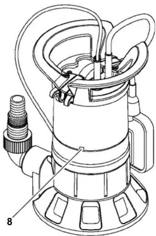
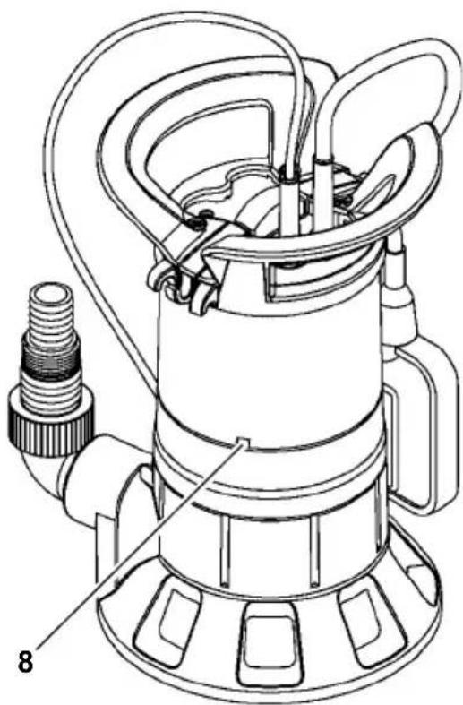
Technical line drawing of a mechanical device with no visible text or symbols1 Power cable with plug
2 Handle / lifting eye
3 Float switch (not for TP 6600)
4 Suction inlets
5 Pump casing
6 Discharge port incl. elbow with multi-adapter
7 Float switch level control
8 Vent (position dependent on model)
2. Please Read First!
- Read these instructions in full before operating. Pay special attention to the safety instructions.
- These instructions are intended for persons with basic technical knowledge in handling tools such as the one described here. If you have no experience with this type of tool we strongly recommend that you seek the advice of an experienced person before operating this tool.
- If you notice transport damage while un- packing, notify your supplier immediately. Do not operate the tool!
- Dispose of the packing in an environmentally friendly manner. Take to a proper collection point.
- Keep all documents supplied with the tool for future reference. Retain your proof of purchase for any future warranty claims.
- If you lend or sell this tool be sure to include the documents supplied with the tool.
- The equipment manufacturer is not liable for any damage arising from disregard of these instructions.
Information in these operating instructions is designated as shown below:

Danger!
Risk of personal injury or environmental damage.

Risk of electric shock!
Risk of personal injury from electric shock.

Caution!
Risk of material damage

Note:
Additional information.
- Numbers in illustrations (1, 2, 3 ...)
– indicate component parts;
- are consecutively numbered; and
– refer to the corresponding numbers in brackets (1), (2), (3) ... in the neighbouring text.
– Numbered steps must be carried out in sequence.
- Instructions which can be carried out in any order are indicated by bullet points (•).
- List items are indicated by dashes (-).
3. Safety
3.1 Specified conditions of use
The pump is intended solely for private use for draining flooded house and garden areas.
Approved pumping media
Submersible clean water pumps: clean water Submersible dirty water pumps: clean or dirty water.
– The suspended solids content in the dirty water must not exceed 5%.
- The particle sizes of the solids in the dirty water must not exceed the maximum particle size specified in the technical data.
Any other use is considered to be not as specified and not allowed.
Typical application areas
- Drainage of containers, water tanks, swimming pools, soakaways and flooded rooms
– Irrigation of gardens and lawns.
Unspecified use
The pump is not intended for:
- pumping fluids at a temperature >35^ ;
– supplying drinking water or pumping liquid food; - pumping salt water;
- pumping explosive, inflammable, aggressive or health-damaging substances or human waste;
– commercial or industrial use; or
– continuous circulation (pond).
The pump should not be used by people (including children and youths) who:
– have physical and/or mental impairments;
– have impaired senses;
– do not have adequate experience and/or knowledge in handling the pump; or
– have not read and understood the operating instructions.
The manufacturer assumes no liability for damage caused by unspecified use.
Unspecified use, modification of the pump or use of parts that have not been tested and approved by the manufacturer can cause unforeseeable damage!
3.2 General safety instructions
- When using this pump observe the following safety instructions to exclude the risk of personal injury or material damage.
– Follow the legal guidelines or accident prevention regulations for use of submersible pumps. - When the pump is being used in swimming pools and garden ponds and in the protected areas around them, the regulations must be observed in accordance with DIN VDE 0100-702 and -738.
All local regulations pertaining to the safe operation of submersible pumps must also be followed. - The pump must be protected by a residual current device (RCD) with a trip current of max 30 mA.

General danger!
Do not operate the pump if anyone is in contact with the pumping media (e.g. in the swimming pool or garden pond)!
The following residual risks do principally exist when operating submersible pumps and can not be fully eliminated – even by employing safety devices.

Danger from the environment!
Do not use the pump in hazardous locations or near inflammable liquids and gases!

Danger: Hot water!
If the shut-off pressure of the pressure switch cannot be reached due to poor pressure conditions or a defective pressure switch the water can heat up within the pump as a result of internal circulation. Through this the pump and the connection lines can become damaged or leaky, allowing hot water to escape. Danger of scalding!
- Do not operate the pump against a closed pressure line for longer than 5 minutes.
- Unplug the pump and allow to cool. A specialist must check the system to make sure it is in perfect working order before it can be used again.

Danger! Risk of electric shock!
Do not touch the plug with wet hands! To unplug always pull on the plug, not the power cable.
Connect only to an earthed outlet that is properly installed, earthed and tested. Mains voltage and fuse protection must correspond to those stated in the 'Technical Specifications'.
Always lift and transport the pump by the handle, never by the power cable or discharge hose.
Extension cables must have sufficient conductor cross sections. Unroll cable reels fully.
Do not buckle, squeeze, drag or drive over power cable or extension cables; protect from sharp edges, oil and heat.
Place extension cable so that it can not get into the fluid to be pumped.
Always unplug before servicing the pump.

Risk of electric shock from pump
faults!
Before each use check the equipment, especially the power and extension cables, power plug and float switch for possible damage. Risk of fatal electric shock!
Do not attempt to repair the pump yourself! When repaired inexpertly there is a hazard of liquid entering the electrical parts of the pump.

Caution!
To avoid water damage, e.g. flooded rooms, caused by pump malfunctions or defects:
• provide for suitable safety measures such as the following:
- alarm or
– collection tank with monitoring.
The manufacturer is not liable for any damage caused by:
- improper use of the pump;
– overloading of the pump through continuous operation;
– failure to operate and store the pump in a frost-free environment; - unauthorised modification of the pump (repairs to electrical equipment may only be carried out by qualified electricians!);
– use of spare parts which have not been tested and approved by the manufacturer; or
– use of unsuitable installation materials (fittings, connection lines etc.).
Suitable installation materials:
– pressure-resistant (min. 10 bar)
- heat-resistant (min. 100°C).
4. Assembly and Installation
4.1 Assembling the handle / lifting eye
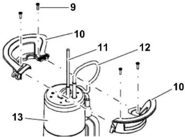
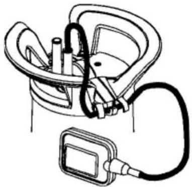
- Bring the two halves of the handle (10) together as illustrated above. Run the power supply cable (11) and float switch cable (12) out the top.
- Join the two halves of the handle (10). Ensure that the guides on the two handle parts engage.
- Secure the handle with the four screws (9) to the pump casing (13). Use the supplied screws only.
4.2 Connecting the discharge line
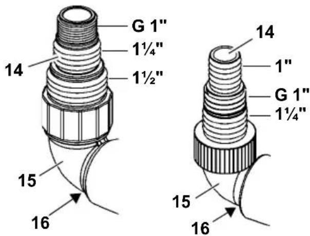
PS 18000 SN All other models
- For selection of the largest discharge line diameter: cut the smaller attachment off the multi- adapter (14).
Note:
The best pump capacity is achieved through selection of the largest discharge line diameter.
- Screw the multi-adapter (14) on to the elbow (15).
- Screw the elbow incl. multi-adapter on to the discharge port (16).
- Slide the discharge line over the multi-adapter (14) and secure with a hose clamp.
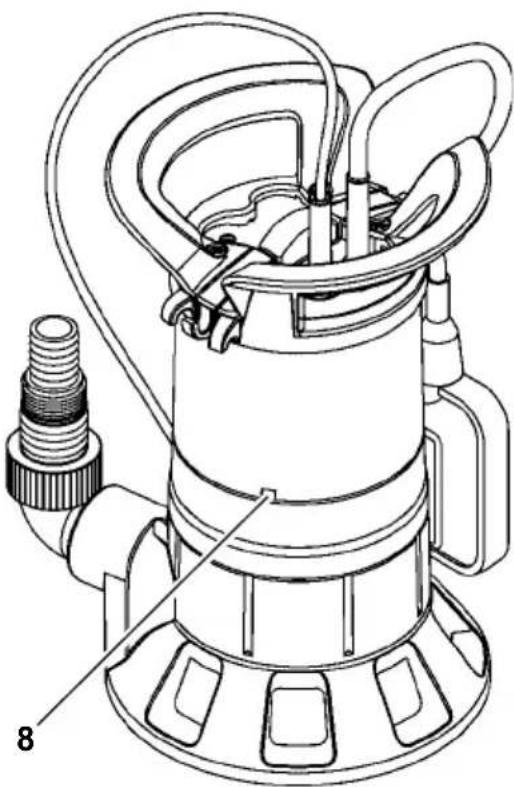
4.3 Fixing the float switch cable
Note:
Fix the float cable such that the distance between the cable holder and the float switch is at least 100 mm.
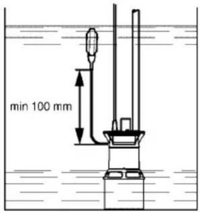
- Form a loop with the float switch cable. Lay the loop as illustrated over the centre hook (18) on the cable holder and guide the float switch cable under the two outside hooks (17).

The following illustration shows the fixed float switch cable:
natural_image
Diagram of a car interior with hoses and a device connected to a motor (no text or symbols)Caution!
The float switch cable may be damaged. Never pull on the float switch cable to change its position in the cable holder! To detach the float switch cable carry out the steps in reverse order.
4.4 Installation instructions
- Space required: approx. 50 x 50 cm. In order for the float switch to function properly it must be able to move freely.
- Submerge the pump to no more than the maximum immersion depth specified in the technical data.
- Install the pump such that the suction inlets cannot be blocked by foreign objects. If necessary place the pump on a support surface.
- Ensure sufficient upright stability.
Risk of electric shock from severed cables!
Do not lift or transport the pump by the cables or the discharge hose! The cables and the discharge hose are not designed to withstand the tensile stress produced by the weight of the pump.
4.5 Installing the pump
- Submerge pump at a slight angle to avoid creating an air cushion on the underside, which would prevent priming. Once the pump is submerged, it can be placed upright.
- Lower pump to the bottom of the fluid container.
Use a strong rope fastened to the lifting eye to lower the pump.
The pump can also be operated when suspended by a rope.
- Before operating the pump again ensure that the pump line has been completely emptied. When doing so vent the pump if necessary.
5. Operation
5.1 Switching ON and OFF
TP 6600
The pump will start immediately after you have connected it to the mains. It will shut off after you have disconnected it from the mains.
All other models
After you have connected the pump to the mains it will be switched on (19) and off (20) automatically by the float switch. The point in time at which switching occurs depends on the water level.
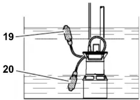
Adjusting the ON and OFF times for the pump
The position of the float switch cable in the cable holder can be changed. The time interval between pump switch-on and switch-off is thereby adjusted:
- 'Short' float switch cable: ON and OFF positions are close together.
- 'Long' float switch cable: ON and OFF positions are far apart.

Caution!
The pump may run dry and thereby be damaged.
The float switch must always be able to move up and down to allow the pump to be switched on and off.

Danger from faulty pump!
Take appropriate measures to ensure that pump faults do not cause consequential
damage through flooding of rooms. This must be ensured, for example, through installation of an alarm system or a reserve pump.

Danger!
Do not let the pump run against a closed pump line.
5.2 Shallow water suctioning (TPF ... models)
- Fasten the float switch upright to the handle to enable suctioning of shallow water.

Risk of material damage from dryning of pump!
The pump can overheat and be damaged as the cooling function of the pumped medium is not active during suctioning of shallow water. The thermal switch will react.
- Only suction shallow water for a short period of time.
- Supervise the pump during suctioning of shallow water.
6. Pump Care

Danger!
Unplug before maintaining or cleaning. Repair and maintenance work other than described in this section should only be carried out by qualified specialists.
6.1 Routine care
For the pump to function perfectly at all times routine care is required. This also applies if the pump is not switched on for extended periods of time (e.g. during operation in soakaways).
Cleaning the pump
- Rinse pump with clean water. Remove persistent marks, e.g. algae deposits, with brush and dishwashing liquid.
- To rinse the inside of the pump: dip pump into a container of clean water and switch on briefly.
Cleaning the impeller
- Undo Phillips screws on pump base plate. If necessary push back the two clips on pump base plate using a screwdriver.
- Remove base plate.
- Clean impeller.
- Mount base plate, fasten screws and if necessary secure with the clips.
6.2 Pump storage
Caution!
Frost damages the pump and accessories as both always contain water!
- If there is a danger of frost disassemble pump and accessories and store in frost-free conditions.
7. Troubleshooting
Danger! Prior to all servicing: Unplug.
7.1 Troubleshooting guide
Pump does not run:
- No mains voltage.
- Check cables, plug, outlet and mains fuse.
- Mains voltage too low.
- Use an extension cable with sufficient conductor diameter.
- Motor overheated; motor protection relay tripped.
- Eliminate the cause of overheating (pump blocked by foreign objects?).
- After cooling the pump will switch ON again.
- Float switch does not switch pump ON when water level rises.
- Make sure the float switch can move unrestrictedly.
If, despite sufficient mobility of the float switch, the pump does not switch ON: send the pump to the service centre in your country.
Motor hums, but does not start:
- Pump blocked by foreign objects.
- Clean impeller.
Pump runs, but does not pump properly:
• Delivery head too high.
- Observe max delivery head (see 'Technical Specifications').
• Discharge hose kinked.
– Straighten discharge hose.
• Discharge hose leaky.
- Seal discharge hose; tighten screw fittings.
Pump runs very noisily:
- Pump is sucking air.
- Ensure there is a sufficient water supply.
– Foreign objects are present (clean pump). - Manual mode has been set (shallow water suctioning).
– Hold pump at an angle when submerging.
Pump runs continuously:
- Float switch does not reach cut-out position.
- Make sure the float switch can move unrestrictedly.
8. Repairs
Danger!
Repair of power tools must be carried out by qualified electricians only!
Power tools in need of repair can be sent to the service centre in your country. Refer to spare parts list for address.
Please attach a description of the fault to the power tool.
9. Disposal
Power tools do not belong in the household rubbish. According to European
Directive 2002/96/EC on waste electrical and electronic equipment, electrical waste must
be collected separately and taken to an environmentally friendly recycling facility.
Contact your local council for information on disposal of the used tool.
All packaging materials are recyclable.

natural_image
Technical line drawing of a mechanical device with no visible text or symbolsnatural_image
Diagram of a medical or laboratory setup with tubing and components, no visible text or symbolsAttention!

natural_image
Technical line drawing of a mechanical device with no visible text or symbolsnatural_image
Line drawing of a car interior with hoses and a small device attached (no text or symbols)Let op!

natural_image
Technical line drawing of a mechanical device with no visible text or symbolsPS 18000 SN Alle andre modeller
- Ved størst mulig valgt diameter på trykledning:
natural_image
Diagram of a car interior with hoses and a connector (no text or symbols)NB!

natural_image
Technical line drawing of a mechanical device with no visible text or symbolsPS 18000 SN Alla andra model-ler
natural_image
Diagram of a car interior with hoses and a connector (no text or symbols)Varning!
Flottörkabeln kan skadas.

natural_image
Technical line drawing of a mechanical device with no visible text or symbolsnatural_image
Diagram of a car interior with hoses and a handheld device (no text or symbols)Tähelepanu!
natural_image
Technical line drawing of a mechanical device with no visible text or symbols1 Strāvas kabelis ar kontaktspraudni
2 Rokturis / piekabināšanas cilpa
3 Schwimmerschalter (nav modelim TP 6600)
natural_image
Diagram of a car interior with hoses and a connector (no text or symbols)
Uzmanību!
natural_image
Technical line drawing of a mechanical device with no visible text or symbolsPS 18000 SN Visi kiti modeliai
LT LIETUVIŠKAI
natural_image
Medical illustration showing a laparoscopic device connected to a patient's seat (no text or labels)Dèmesio!

natural_image
Technical line drawing of a mechanical device with no visible text or symbolsnatural_image
Diagram of a medical or laboratory setup with tubing and components, no visible text or symbolsΠροσοχή!


- D DEUTSCH
- Please Read First!
- Danger!
- Risk of electric shock!
- Caution!
- Note:
- Safety
- Specified conditions of use
- Approved pumping media
- Typical application areas
- Unspecified use
- General safety instructions
- General danger!
- Danger from the environment!
- Danger: Hot water!
- Danger! Risk of electric shock!
- Risk of electric shock from pump
- faults!
- To avoid water damage, e.g. flooded rooms, caused by pump malfunctions or defects:
- Assembly and Installation
- Assembling the handle / lifting eye
- Connecting the discharge line
- Fixing the float switch cable
- Installation instructions
- Risk of electric shock from severed cables!
- Installing the pump
- Operation
- Switching ON and OFF
- TP 6600
- All other models
- Adjusting the ON and OFF times for the pump
- Danger from faulty pump!
- Shallow water suctioning (TPF ... models)
- Risk of material damage from dryning of pump!
- Pump Care
- Routine care
- Cleaning the pump
- Cleaning the impeller
- Pump storage
- Frost damages the pump and accessories as both always contain water!
- Troubleshooting
- Danger! Prior to all servicing: Unplug.
- Troubleshooting guide
- Pump does not run:
- Motor hums, but does not start:
- Pump runs, but does not pump properly:
- Pump runs very noisily:
- Pump runs continuously:
- Repairs
- Disposal
- Attention!
- Let op!
- NB!
- Varning!
- Tähelepanu!
- Uzmanību!
- LT LIETUVIŠKAI
- Dèmesio!
- Προσοχή!
Brand : METABO
Model : TPF 7000 S
Category : Pump