
A9130 - AV receiver ONKYO - Free user manual and instructions
Find the device manual for free A9130 ONKYO in PDF.
| Product Type | Stereo Integrated Amplifier |
| Rated Output Power (IEC) | 2 × 60 W (4 Ω, 20 Hz-20 kHz, 0.5% THD); 2 × 30 W (8 Ω, 20 Hz-20 kHz, 0.4% THD) |
| Power Supply | AC 220-230 V, 50/60 Hz |
| Power Consumption | 150 W (On); 0.2 W (Standby) |
| Audio Inputs | 5 × LINE (RCA), 1 × PHONO (MM), 1 × Digital Coaxial (D1), 1 × Digital Optical (D2) |
| Audio Outputs | 1 × LINE OUT (RCA), 1 × SUBWOOFER PRE OUT, 1 × MAIN IN (RCA), 1 × Headphone (6.3 mm), L/R Speaker Terminals |
| Compatible Speaker Impedance | 4 Ω to 16 Ω |
| Frequency Response | 10 Hz - 100 kHz (+1 dB, -3 dB, DIRECT mode) |
| Special Functions | DIRECT mode, Phase Matching Bass, RI (Remote Interactive) |
| Phono Input | Yes, for MM cartridge, sensitivity 4 mV/47 kΩ |
| Remote Control | RC-968S (included), AAA batteries × 2 |
| Other Connectors | RI REMOTE CONTROL (jack), GND terminal for turntable |
| Safety | Protection against overheating and short circuits; ventilation required (20 cm above and sides, 10 cm at rear) |
| Maintenance | Clean with a soft dry cloth; do not use solvents |
| Supplied Accessories | Remote control, batteries, power cord, instruction manual |
Frequently Asked Questions - A9130 ONKYO
User questions about A9130 ONKYO
0 question about this device. Answer the ones you know or ask your own.
Ask a new question about this device
Download the instructions for your AV receiver in PDF format for free! Find your manual A9130 - ONKYO and take your electronic device back in hand. On this page are published all the documents necessary for the use of your device. A9130 by ONKYO.
USER MANUAL A9130 ONKYO
INTEGRATED AMPLIFIER
A-9130
Instruction Manual
Before use
2
Preparations
8
Basic Operations
16
Others
20
Table of Contents What's in the box
Before use
What's in the box 2
Safety Information 3
Part Names 4
Front Panel 4
Rear Panel 5
Remote Controller 6
Preparations
Connections 8
Connecting speakers 8
Connecting a Powered subwoofer 9
Connecting players (DIGITAL IN connection) .... 9
Connecting players (LINE IN connection) 10
Connecting players (Turntable connection) .... 10
Connecting with Onkyo RI Components 11
Using this unit as a power amplifier 12
Power Cord Hookup. 12
Setup 13
Remote controller preparations 13
Turn on the power of the unit 13
Speaker impedance settings 14
RI function settings 15
Basic Operations
Playback 16
Switching input and adjusting the volume 16
Subwoofer output settings 17
Using the Direct Function 18
Adjusting the sound quality and balance 18
Switching the unit to power amplifier mode 19
Others
Useful functions 20
Setting auto standby 20
Troubleshooting 21
Specifications 23

-
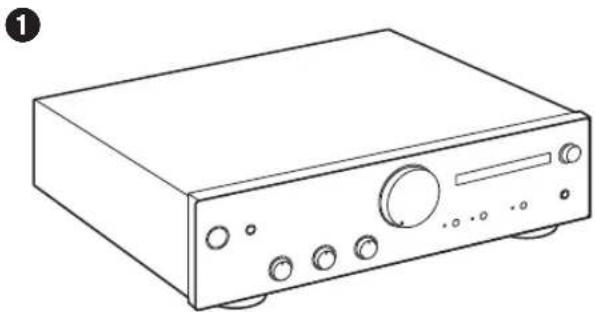
Main unit (1)
-
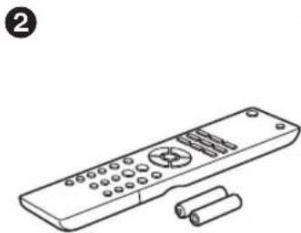
Remote controller (RC-968S) (1), batteries (AAA/R03) (2)
-
Power Cord (1)
-
Instruction Manual (This document)
-
Connect speakers with 4 to 16 impedance.
- The power cord must be connected only after all other cable connections are completed.
- We will not accept responsibility for damage arising from the connection of equipment manufactured by other companies.
- Specifications and appearance are subject to change without prior notice.
Safety Information


The lightning flash with arrowhead symbol, within an equilateral triangle, is intended to alert the user to the presence of uninsulated "dangerous voltage" within the product's enclosure that may be of sufficient magnitude to constitute a risk of electric shock to persons.

The exclamation point within an equilateral triangle is intended to alert the user to the presence of important operating and maintenance (servicing) instructions in the literature accompanying the appliance.
CAUTION:
TO PREVENT THE RISK OF ELECTRIC SHOCK, DO NOT REMOVE COVER (OR BACK). NO USER-SERVICEABLE PARTS INSIDE. REFER SERVICING TO QUALIFIED SERVICE PERSONNEL.
WARNING
TO PREVENT THE RISK OF ELECTRIC SHOCK, DO NOT REMOVE COVER (OR BACK). NO USER-SERVICEABLE PARTS INSIDE. REFER SERVICING TO QUALIFIED SERVICE PERSONNEL.
This equipment is not waterproof. To prevent a fire or shock hazard, do not place any container filled with liquid near this equipment (such as a vase or flower pot) or expose it to dripping, splashing, rain or moisture.
To prevent a fire hazard, do not place any naked flame sources (such as a lighted candle) on the equipment.
Store small parts out of the reach of children and infants. If accidentally swallowed, contact a doctor immediately.
Slots and openings in the cabinet are provided for ventilation to ensure reliable operation of the product, and to protect it from overheating. To prevent fire hazard, the openings should never be blocked or covered with items (such as newspapers, tablecloths, curtains) or by operating the equipment on thick carpet or a bed.
Do not use or store batteries in direct sunlight or other excessively hot place, such as inside a car or near a heater. This can cause batteries to leak, overheat, explode or catch fire. It can also reduce the life or performance of batteries.
Risk of explosion if battery is replaced by an incorrect type. Risk of explosion If disposal of a battery into fire or a hot oven, or mechanically crushing or cutting of a battery.
Precautions
If you install the apparatus in a built-in installation, such as a bookcase or rack, ensure that there is adequate ventilation.
Leave 20cm ( 8'' ) of free space at the top and sides and 10cm ( 4'' ) at the rear. The rear edge of the shelf or board above the apparatus shall be set 10cm ( 4'' ) away from the rear panel or wall, creating a flue-like gap for warm air to escape.
Operating Environment
Operating environment temperature and humidity: +5^ to +35^ (+41^ to +95^) less than 85% RH cooling vents not blocked
Do not install this unit in a poorly ventilated area, or in locations exposed to high humidity or direct sunlight (or strong artificial light).
Important Notice
The model number and serial number of this equipment are on the rear or bottom. Record these numbers on your enclosed warranty card and keep in a safe place for future reference.
CAUTION
The power switch on this unit will not completely shut off all power from the AC outlet. Since the power cord serves as the main disconnect device for the unit, you will need to unplug it from the AC outlet to shut down all power. Therefore, make sure the unit has been installed so that the power cord can be easily unplugged from the AC outlet in case of an accident. To avoid fire hazard, the power cord should also be unplugged from the AC outlet when left unused for a long period of time (for example, when on vacation).
This product is for general household purposes. Any failure due to use for other than household purposes (such as long-term use for business purposes in a restaurant or use in a car or ship) and which requires repair will be charged for even during the warranty period.
Power-Cord Caution
Handle the power cord by the plug. Do not pull out the plug by tugging the cord and never touch the power cord when your hands are wet as this could cause a short circuit or electric shock. Do not place the unit, a piece of furniture, etc., on the power cord, or pinch the cord. Never make a knot in the cord or tie it with other cords. The power cords should be routed such that they are not likely to be stepped on. A damaged power cord can cause a fire or give you an electrical shock. Check the power cord once in a while. When you find it damaged, ask your nearest our authorized service center or your dealer for a replacement.
For European models
Information for users on collection and disposal of old equipment and used batteries
Symbol for equipment
Symbol examples for batteries


These symbols on the products, packaging, and/or accompanying documents mean that used electrical and electronic products and batteries should not be mixed with general household waste.
For proper treatment, recovery and recycling of old products and used batteries, please take them to applicable collection points in accordance with your national legislation.
By disposing of these products and batteries correctly, you will help to save valuable resources and prevent any potential negative effects on human health and the environment which could otherwise arise from inappropriate waste handling.
For more information about collection and recycling of old products and batteries, please contact your local municipality, your waste disposal service or the point of sale where you purchased the items.
These symbols are only valid in the European Union. For countries outside the European Union:
If you wish to discard these items, please contact your local authorities or dealer and ask for the correct method of disposal.
WEEE
http://www.onkyo.com/manual/weee/weee.pdf
Part Names
Front Panel
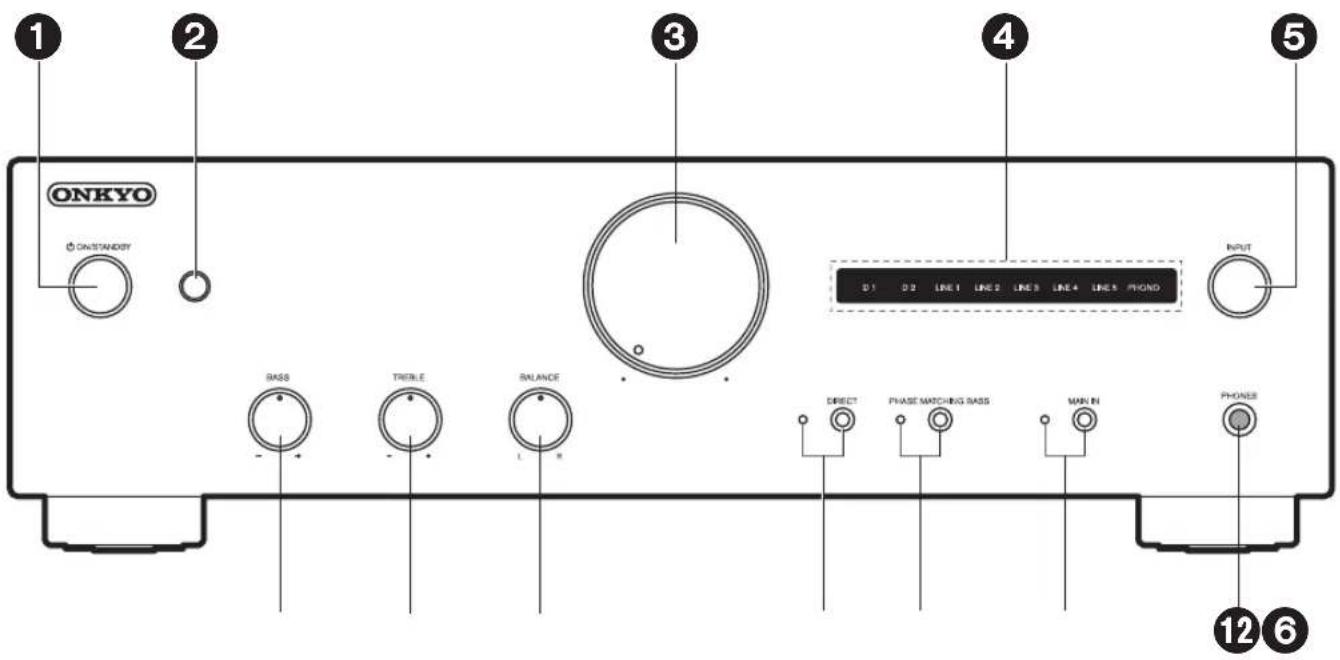
- ON/STANDBY button
- Remote control sensor: Receives signals from the remote controller.
The signal range of the remote controller is within about 16^ / 5m at an angle of 20^ on the perpendicular axis and 30^ to either side.
- Volume controller
- Input source indicators: The indicators light according to the selected input source.
The indicator for the selected input source blinks when MUTING ( p6) is active. - INPUT dial: Switches the input source to be played.
- BASS -/+ controller: Enhance or moderate the bass range of the speakers. ( p18)
- TREBLE - / + controller: Enhance or moderate the treble range of the speakers. ( p18)
- BALANCE L/R controller: Adjust the left/right audio balance. ( p19)
- DIRECT button/indicator: Switch the DIRECT feature on and off. The indicator lights when the DIRECT feature is on. ( p18)
- PHASE MATCHING BASS button/indicator: Switch the PHASE MATCHING BASS feature on and off. The indicator lights when the PHASE MATCHING BASS feature is on. ( p18)
- MAIN IN button/indicator: Button for making settings when this unit is used as a power amplifier. The indicator lights when the mode to use this unit as a power amplifier is on. ( p19)
12.PHONES jack: Connect stereo headphones with a standard plug ( 1 / 4^ / 6.3mm diameter).
Rear Panel
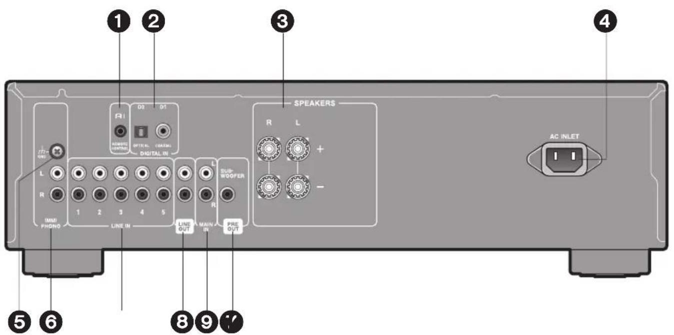
- RI REMOTE CONTROL jack: This jack is for linking when you connect an Onkyo CD player, tuner, network audio player, or RI dock that has an RI ("Remote Interactive") jack. ( p11)
- DIGITAL IN COAXIAL D1/DIGITAL IN OPTICAL D2 jacks: Input digital audio signals from a playback device with a digital coaxial cable or digital optical cable. ( p9)
- SPEAKERS terminals: Connect speakers with speaker cables. (Not compatible with connection using banana plugs or Y plugs.) ( p8)
- AC INLET: Connect the supplied power cord. ( p12)
- GND terminal: The ground wire of the turntable is connected.
- PHONO (MM) jacks: Use an Analog audio cable to connect a Turntable that uses an MM type cartridge. ( p10)
- LINE IN jacks: Input audio signals from a playback device with an analog audio cable. ( p10)
- LINE OUT jacks: Use an Analog audio cable to output audio signals to recording equipment, such as a cassette tape deck. To select the input source for recording, use the INPUT dial on this unit or use the remote controller.
- MAIN IN jacks: When using this unit as a power amplifier, connect the pre-amplifier here. ( p12)
10.SUBWOOFER PRE OUT jack: Connect a powered subwoofer with a subwoofer cable. ( p9)
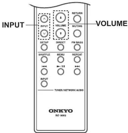
Remote Controller
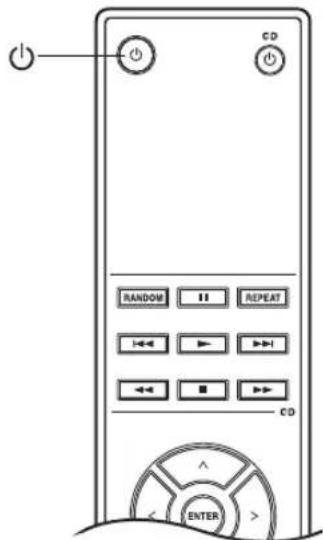
Operating this unit
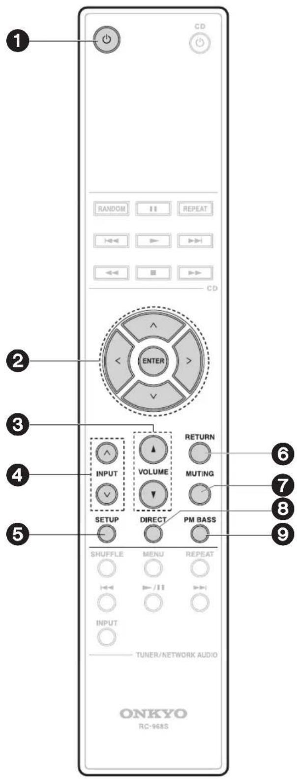
- button: Sets this unit to On or Standby.
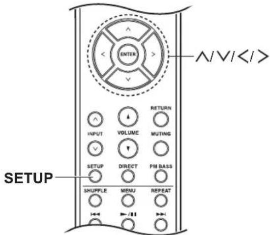
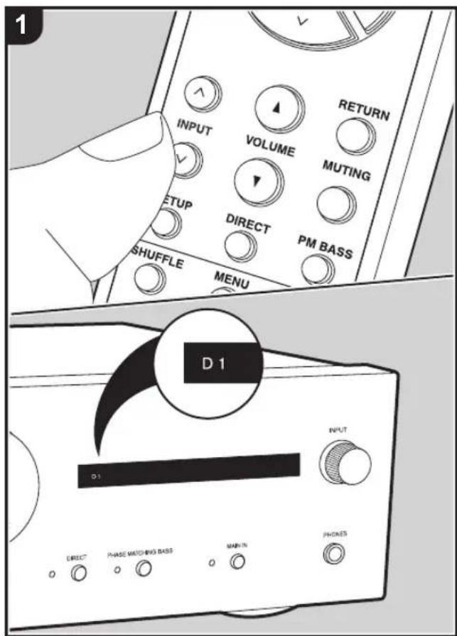
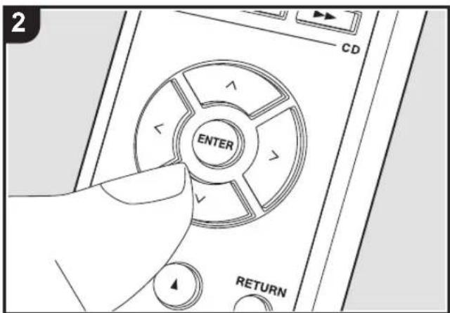
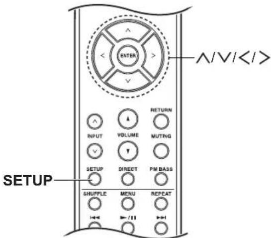
- Cursor ( / / < / >) , ENTER button: Select the item with the cursors and press ENTER to confirm.
- VOLUME buttons
- INPUT( ∧ / ∨ ) buttons: Switches the input source to be played.
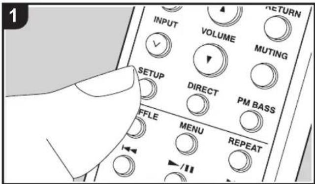
- SETUP button: Switches to the settings menu. Make speaker impedance settings ( p14) , RI function settings ( p15) , subwoofer output settings ( p17) , and auto standby settings ( p20) .
- RETURN button: Returns the display to the previous display/state during setting.
- MUTING button: Temporarily mutes audio. Press again to cancel muting.
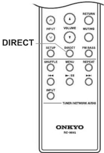
- DIRECT button: Switch the DIRECT feature on and off. ( p18)
- PM BASS button: Switch the PHASE MATCHING BASS feature on and off. ( p18)
You can operate Onkyo CD players, tuners, network audio players, and RI docks with the remote controller of this unit.
Operating an Onkyo CD player
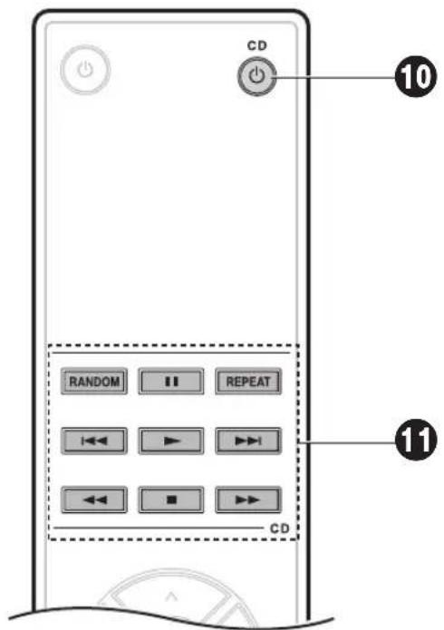
Point the remote controller at the CD player's remote control sensor and operate.
10.CD button
11.Play mode buttons
- If you have a Network CD player, then the RI function enables use of the 12 and 13 buttons when you connect it with an RI cable ( p11). When using these buttons, point the remote controller at the remote control sensor of this unit.
Operating an Onkyo tuner, network audio player, or Rl dock
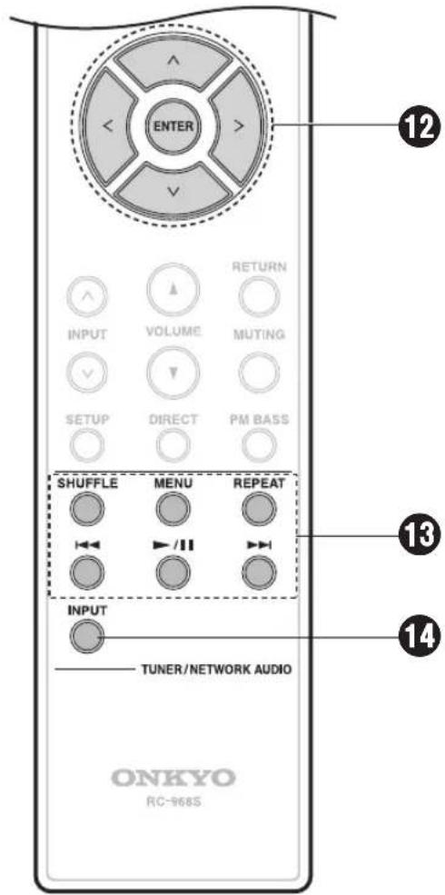
You can use the RI function to centrally control with the remote controller of this unit by connecting this unit and the other audio components with an RI cable ( p11) . Point the remote controller at the remote control sensor of this unit to operate.
-
Cursor buttons ( / / < / >) , ENTER button: Select items with the cursor buttons and press ENTER to confirm.
-
Play mode buttons
-
When using a network audio player, pressing the MENU button returns to the previous display/state during setting.
-
INPUT button
-
When using a tuner, this works as a BAND button.
The INPUT button is not used for RI docks.
Connections
Connecting speakers
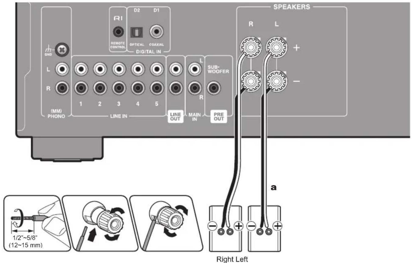
a Speaker Cable
(Note) Speaker Impedance
Connect speakers with an impedance of 4 to 16

Setup: You have to change the setting on this unit if any of the connected speakers have 4 or more to less than 8 impedance. Change the speaker impedance setting to 4 ( p14)
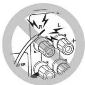
Connect the Speaker Cables
Make correct connection between the unit's jacks and speaker's jacks (+ side to + side, and - side to - side) for each channel. If the connection is wrong, a bass sound will not be reproduced properly due to reverse phase. Twist the wires exposed from the tip of the speaker cable so that the wires do not stick out of the speaker terminal when connecting. If the exposed wires touch the rear panel, or the + side and - side wires touch each other, the protection circuit will be activated.
Connecting a Powered subwoofer
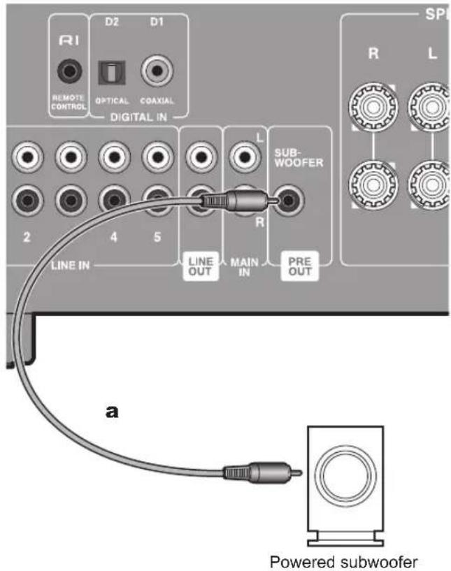
a Subwoofer Cable
You can also connect a Powered subwoofer to the SUBWOOFER PRE OUT jack to boost bass playback even more. Use a subwoofer cable for connection.
You can switch the subwoofer output setting between auto/ on/off according to your preference. Refer to "Subwoofer output settings" ( p17) for details.
- It is recommended to set this off if you are not using a subwoofer.
Connecting players (DIGITAL IN connection)

a Digital Optical Cable, b Digital Coaxial Cable
Use a Digital coaxial cable to connect a player to the DIGITAL IN COAXIAL D1 jack. Alternatively, use a Digital optical cable to connect a player to the DIGITAL IN OPTICAL D2 jack. Refer to "Connecting with Onkyo RI Components" ( p11) to use the RI function.
Only PCM audio is supported for input through the DIGITAL IN OPTICAL/COAXIAL jacks. Set the audio output on the playback device to output PCM.
Connecting players (LINE IN connection)
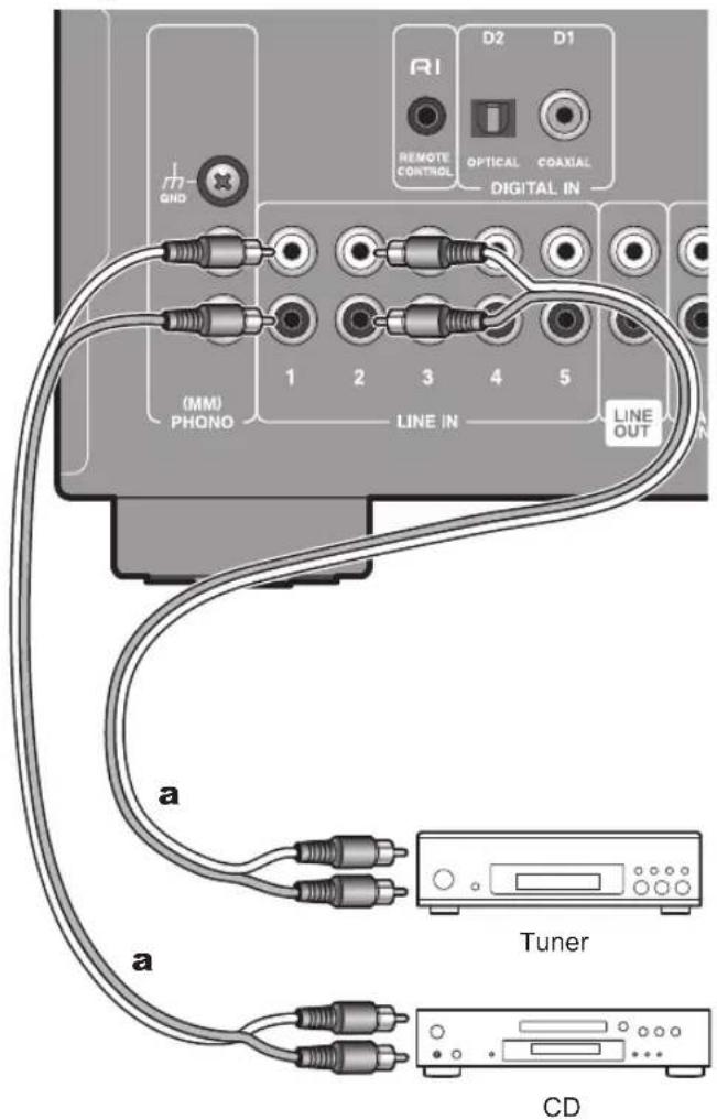
a Analog Audio Cable
Use an Analog audio cable to connect a player to one of the LINE IN 1/2/3/4/5 jacks. Refer to "Connecting with Onkyo RI Components" ( p11) to use the RI function.
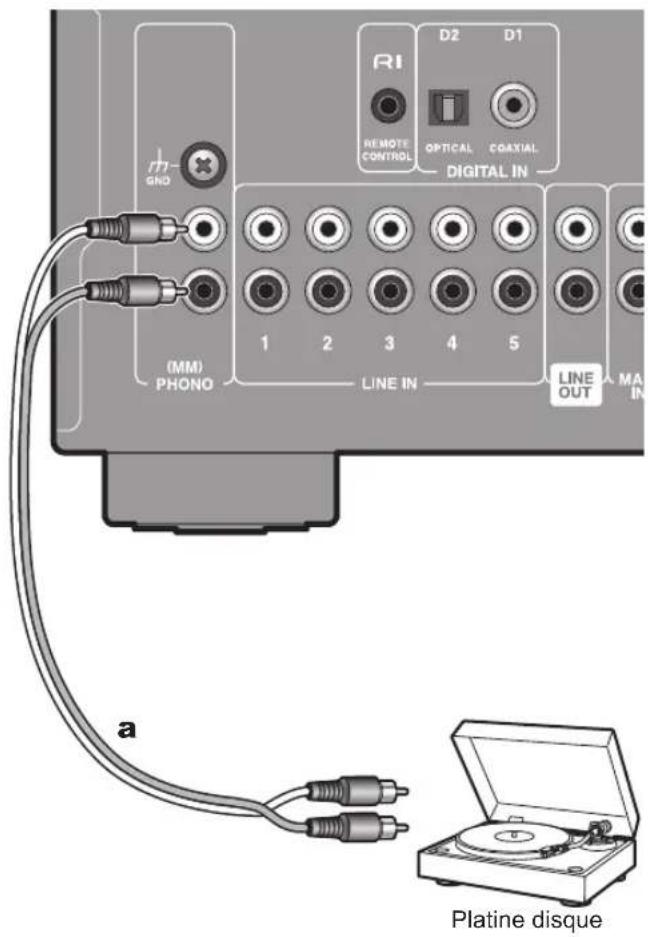
Connecting players (Turntable connection)
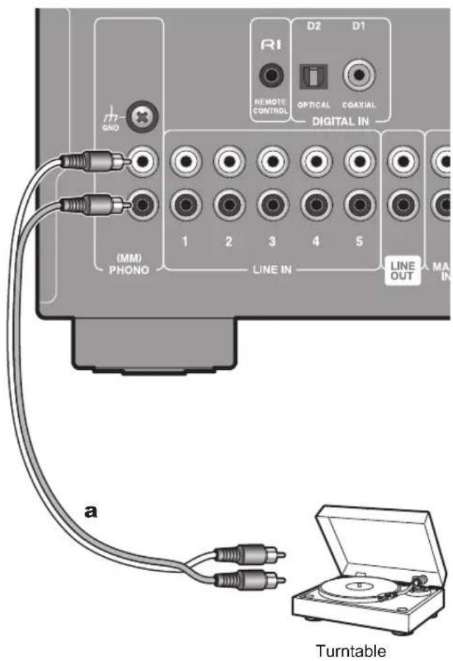
a Analog Audio Cable
Use an analog audio cable to connect a turntable that uses an MM-type cartridge to the PHONO (MM) jack.
If the turntable has a ground wire, connect it to the GND terminal. With some turntables, connecting the ground wire may cause hum, in which case it should be disconnected.
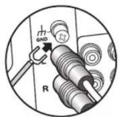
- If the turntable has a built-in audio equalizer, connect it to an LINE IN jack other than the PHONO (MM) jack. Also, if the turntable uses an MC type cartridge, install an audio equalizer compatible with the MC type cartridge between the unit and the turntable, then connect to any LINE IN jack other than the PHONO (MM) jack.
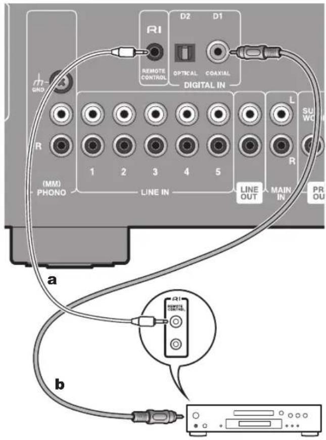
Connecting with Onkyo RI Components
a RI Cable, b Digital Coaxial Cable
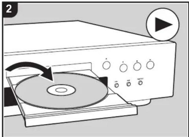
CD
Connection and Setup
If you have an Onkyo CD player, tuner, network audio player, or RI dock, if these have RI jacks, then you can connect them to this unit and link switching between on and standby, and use the remote controller of this unit to centrally control the equipment. (RI function)
These linked operations are enabled by the connection with an RI cable between the equipment with an RI jack and this unit, and the connection using a Digital cable or Analog audio cable. Refer to the following table for connections. When connecting to the DIGITAL IN COAXIAL D1 jack, use a Digital coaxial cable. When connecting to the DIGITAL IN OPTICAL D2 jack, use a Digital optical cable. When connecting to LINE IN 1/2/3, use an Analog audio cable.
| Equipment connected Jack | to connect to |
| CD player (*) DIGITAL IN CO | AXIAL D1 or LINE IN 1 |
| Tuner (*) DIGITAL IN OPTICAL | D2 or LINE IN 2 |
| Network audio player / Rl dock | LINE IN 3 |

(*)Setup: When connecting a CD player or tuner, settings
are required to use the RI function. Refer to "RI function settings" ( p15) for details.
The RI function
The follow system functions can be used with the RL function.
- Some functions may not be supported depending on the product even when an RI connection is used.
Auto Power On
When this unit is in standby mode, if a component connected by an RI cable is turned on, this unit automatically turns on.
Direct change
When playback is started on a component connected via RI, the unit selects that component as the input source.
System off
When this unit is turned off, components connected by an RI cable are automatically turned off.
Remote controller operations
You can use the remote controller of this unit to centrally control components by connecting with an RI cable. Refer to "Remote Controller" - "Operating other components" ( p7) for information about the buttons and operations for the components.
- The RI feature on this unit supports Onkyo CD players, tuners, network audio players, and RI docks only. It does not work properly with other devices such as MD recorders. Refer to the instruction manual of the component with the RI jack for details.
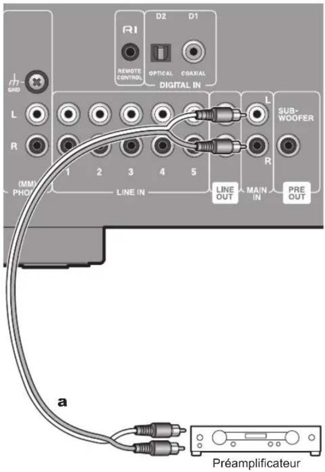
Using this unit as a power amplifier
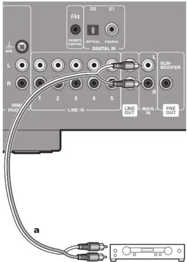
a Analog Audio Cable
Pre-amplifier
Connect your pre-amplifier and you can use this unit as a power amplifier. Connect the MAIN IN jacks of the unit and the PRE OUT jacks of the pre-amplifier with an analog audio cable.
- Do not connect a source device (CD device, etc.) to the MAIN IN jack. Doing so may produce high-volume sound that can damage the unit, speakers, and various other devices.

Setup: Switch the unit to power amplifier mode to use this unit as a power amplifier. ( p19)
Power Cord Hookup
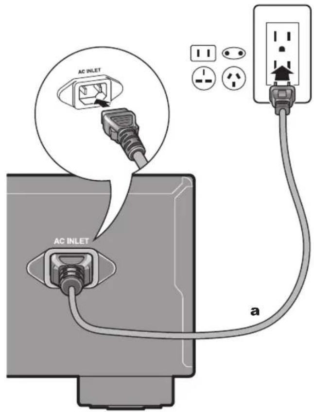
a Power Cord
This model includes a removable power cord. The power cord must be connected only after all other connections are completed. Make sure you first connect the power cord to AC INLET terminal of the unit and then connect to the outlet. Always disconnect the outlet side first when disconnecting the power cord.
Setup
Remote controller preparations
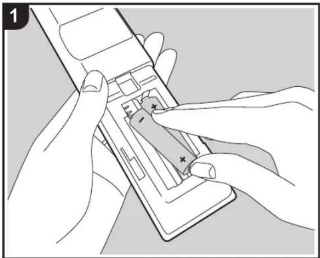
Match the polarity when inserting the batteries.
Turn on the power of the unit
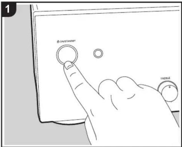
Press ON/STANDBY on this unit or on the remote controller.
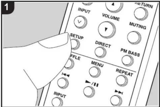
Speaker impedance settings
Depending on the speakers you connect, you may need to change the speaker impedance setting on this unit. Refer to the page describing speaker connection ( p8) and do the following procedures if the change is required.
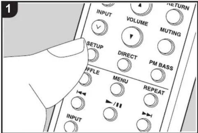
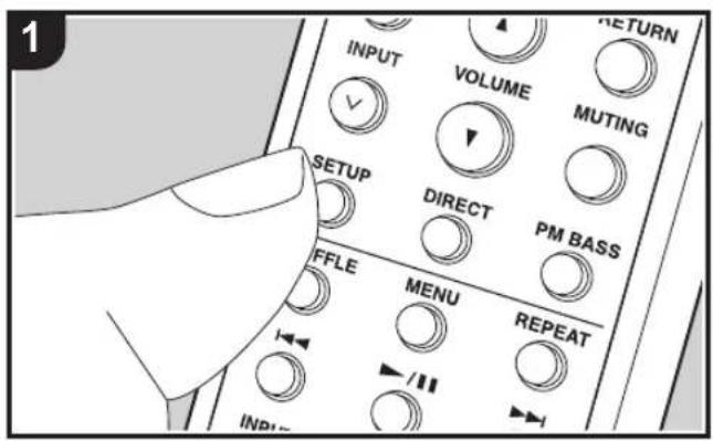
- Press SETUP on the remote controller.
- If this unit is set to be used as a power amplifier, the SETUP button will not work. Check the setting. ( p19)
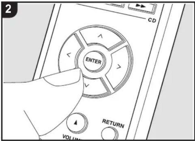
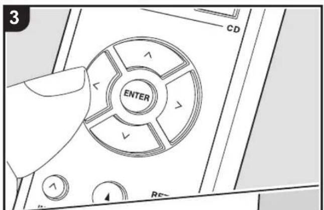
- Press / on the remote controller several times so that input source indicators on the unit, such as "LINE 1" and "LINE 2", start blinking.

(BLINKING)
-
The indicators blink and the current setting is displayed.
-
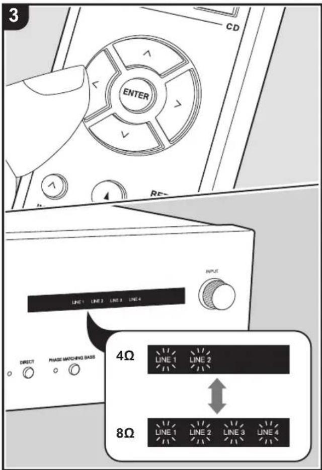
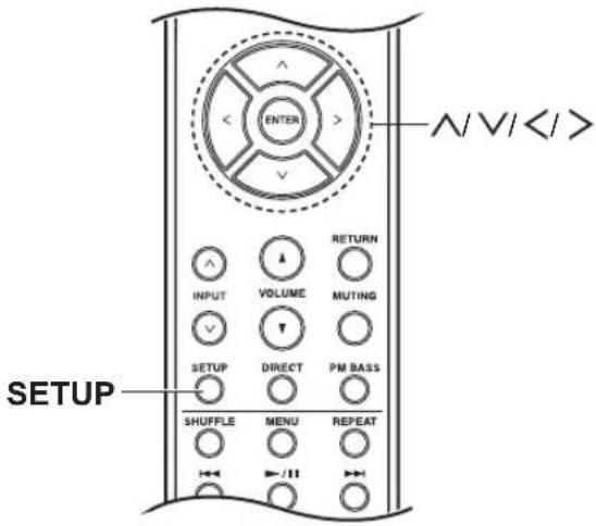
Press < / > on the remote controller to change the setting.
- 4Ω:"LINE1" and "LINE2" indicators are blinking
-
8Ω(default value): "LINE1", "LINE2", "LINE3" and "LINE4" indicators are blinking
-
To exit the settings, press SETUP.
-
The setting mode ends after 5 seconds elapse with no operations performed.
RI function settings

When connecting an Onkyo CD player or tuner to the RI REMOTE CONTROL jack on this unit ( p11) and using the RI function, you need to make RI function settings.
- Press SETUP on the remote controller.
- If this unit is set to be used as a power amplifier, the SETUP button will not work. Check the setting. ( p19)
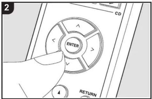
- Press / on the remote controller several times to switch to the RI function setting mode.
- When connecting a CD player, make it so that one of the "D1" and "LINE 1" indicators blinks and the other one lights.
- When connecting a tuner, make it so that one of the "D2" and "LINE 2" indicators blinks and the other one lights.

(BLINKING) (LIGHTING)
-
Press < / > on the remote controller to switch the setting. (When connecting a CD player)
-
When connecting to the DIGITAL IN COAXIAL D1 jack (default value): The "D1" indicator blinks and "LINE 1" lights.
- When connecting to the LINE IN 1 jack: The "LINE 1" indicator blinks and "D1" lights.
(When connecting a tuner)
- When connecting to the DIGITAL IN OPTICAL D2 jack (default value): The "D2" indicator blinks and "LINE 2" lights.
-
When connecting to the LINE IN 2 jack: The "LINE 2" indicator blinks and "D2" lights.
-
To exit the settings, press SETUP.
-
The setting mode ends after 5 seconds elapse with no operations performed.
Playback
Switching input and adjusting the volume
Perform the following procedure when the unit is on.
- Press INPUT/√ on the remote controller to switch to the input with the same name as the jack to which you have connected the player.
For example, switch to D1 to play the device connected to the DIGITAL IN COAXIAL D1 jack.
When operating on the main unit, turn the INPUT dial to switch the input.
The indicator for the selected input source lights.
- If there is no digital audio signal input while D1 or D2 is selected, the indicator blinks while the source is selected.
- Start play on the connected player.
- Press VOLUME on the remote controller or turn the volume controller on the main unit to adjust the volume.
Subwoofer output settings
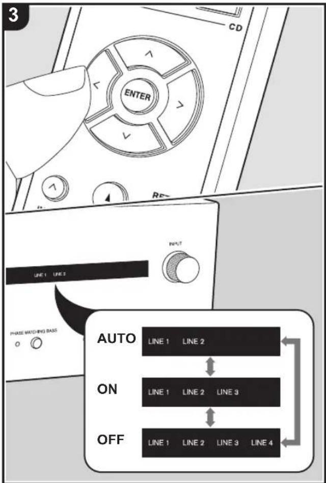
This unit enables you to choose the subwoofer output mode, with the choices being "Auto" (default setting), "On", and "Off".
Auto: The subwoofer signal is not output when the DIRECT function ( p18) is on.
On : The subwoofer signal is always output.
Off: The subwoofer signal output is stopped, and the effect on sound quality can be moderated within the unit. It is recommended to set this off if you are not using a subwoofer.
-
There is no audio output from the subwoofer when headphones are connected, irrespective of the setting.
-
Press SETUP on the remote controller.
If this unit is set to be used as a power amplifier, the SETUP button will not work. Check the setting. ( p19)
- Press / on the remote controller several times so that some input source indicators, such as "LINE 1" and "LINE 2", light on the unit.

(LIGHTING)
The indicators light and the current setting is displayed.
-
Press / on the remote controller to change the setting.
-
Auto (default value): "LINE 1" and "LINE 2" indicators light
- On: "LINE 1", "LINE 2" and, "LINE 3" indicators light
-
Off: "LINE 1", "LINE 2", "LINE 3" and "LINE 4" indicators light
-
To exit the settings, press SETUP.
-
The setting mode ends after 5 seconds elapse with no operations performed.
Using the Direct Function
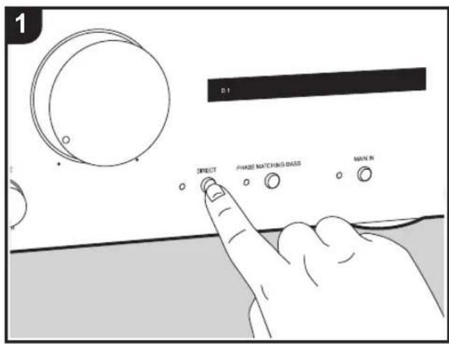
When you turn the DIRECT feature on (default value), the unit bi-passes the tone control circuits that adjust the bass and treble, taking the shortest route which favors sound quality.
PHASE MATCHING BASS/BASS/TREBLE cannot be adjusted when DIRECT feature is on.
1. Press DIRECT on the main unit or the remote controller to switch on or off. The DIRECT indicator lights when on.
Adjusting the sound quality and balance
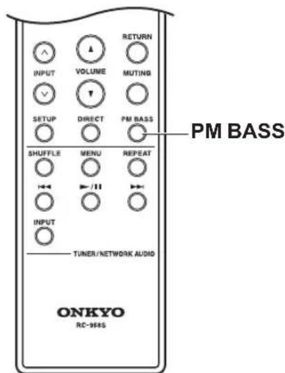
PHASE MATCHING BASS
Turning the PHASE MATCHING BASS function on maintains smooth and powerful bass reproduction while effectively keeping the mid-range clear and making vocals and strings stand out (The default value is "off").
- This cannot be set when DIRECT is on (default value). Press DIRECT to turn the DIRECT indicator off before operating. Note that the PHASE MATCHING BASS setting reverts to the previous setting when the DIRECT function is turned off.
- Press PHASE MATCHING BASS on the main unit or PM BASS on the remote controller to switch on or off. The PHASE MATCHING BASS indicator lights when on.
BASS (main unit only)
- This cannot be set when DIRECT is on (default value). Press DIRECT to turn the DIRECT indicator off before operating.
- Turn the BASS -/+ controller to enhance or moderate the bass.
TREBLE (main unit only)
-
This cannot be set when DIRECT is on (default value). Press DIRECT to turn the DIRECT indicator off before operating.
-
Turn the TREBLE - / + controller to enhance or moderate the treble.
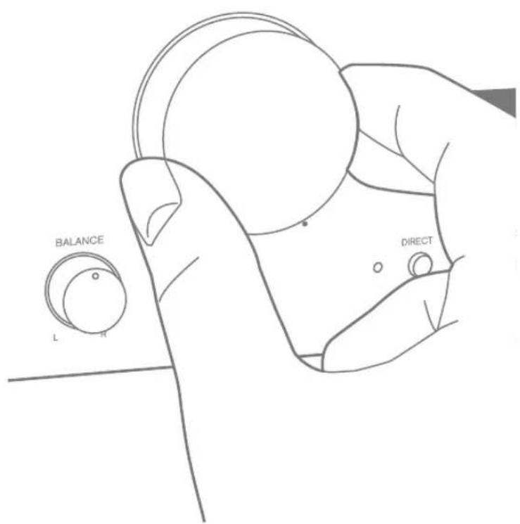
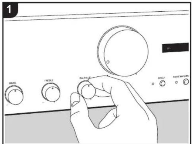
BALANCE (main unit only)
- Turn the BALANCE L/R controller on the main unit to adjust the balance of the sounds output from the left and right speakers.
Switching the unit to power amplifier mode
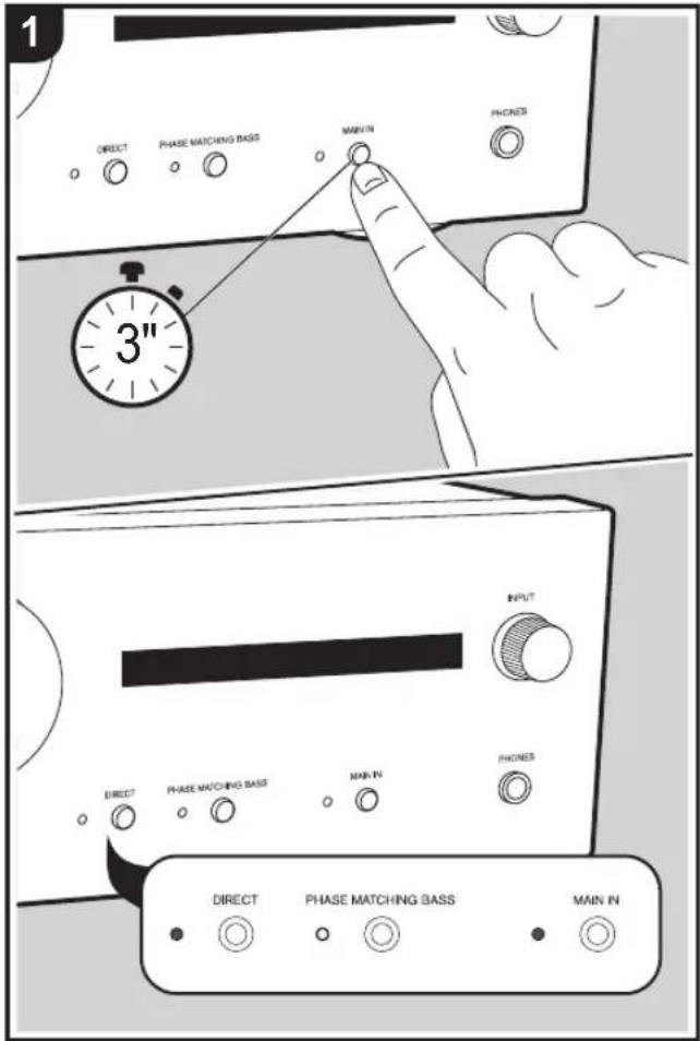
Perform the following operations to switch the unit to power amplifier mode to use this unit as a power amplifier when you have connected a pre-amplifier to the MAIN IN jack on this unit ( p12) .
- Power amplifier modes settings are not available if headphones are connected.
- Press and hold MAIN IN until the "DIRECT" and "MAIN IN" indicators light on the main unit. Press and hold MAIN IN to cancel the power amplifier mode. Note that the power amplifier mode is not canceled even if this unit goes to standby mode.
- When you cancel the power amplifier mode, BASS, TREBLE, BALANCE, DIRECT, and PHASE MATCHING BASS revert to the settings prior to changing to the power amplifier mode.
There is no audio output from the PHONES jack and LINE OUT jacks while the power amplifier mode is engaged. The following functions are also unavailable while the power amplifier mode is on.
Basic Operations
"Speaker impedance settings ( p14) / "RI function settings ( p15) / "Switching input and adjusting the volume ( p16) / "Subwoofer output settings ( p17) / "Adjusting the sound quality and balance ( p18) / "Setting auto standby ( p20)
- When switched to power amplifier mode, if the volume of the connected pre-amplifier is low, auto standby ( p20) may function and the power may automatically switch to standby. If this happens, you may be able to fix it by increasing the volume on the pre-amplifier.
- Also read the instruction manual of the pre-amplifier you connected to this unit.
Useful functions
Setting auto standby

When automatic standby is on (default value), the unit automatically switches to standby mode after 20 minutes of no audio input without any operations.
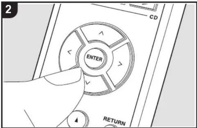
- Press SETUP on the remote controller.
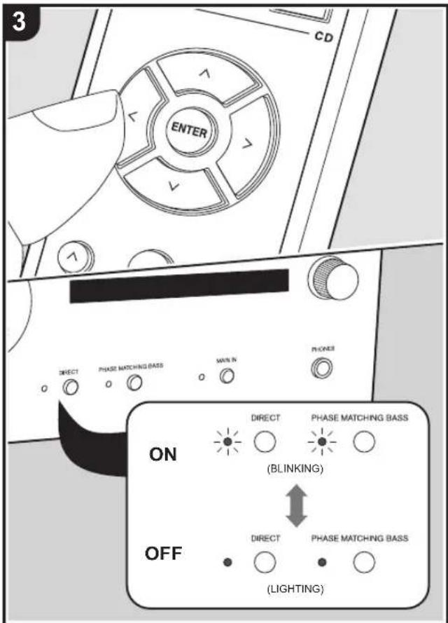
If this unit is set to be used as a power amplifier, the SETUP button will not work. Check the setting. ( p19) - Press / on the remote controller several times to make the "DIRECT" and "PHASE MATCHING BASS" indicators either blink or light.

The indicators blink or light and the current setting value is displayed.
-
Press / on the remote controller to switch auto standby on or off.
-
On (default value): "DIRECT" and "PHASE MATCHING BASS" indicators are blinking
-
Off: "DIRECT" and "PHASE MATCHING BASS" indicators light
-
To exit the settings, press SETUP.
-
The setting mode ends after 5 seconds elapse with no operations performed.
- 60 seconds before switching to standby mode, the input source indicator for the currently selected source starts blinking.
Depending on the connected device, the auto standby feature may not engage due to factors such as noise.
Troubleshooting
Before starting the procedure
Problems may be solved by simply turning the power on/off or disconnecting/connecting the power cord, which is easier than working on the connection, setting and operating procedure. Try the simple measures on both the unit and the connected device. After reconnecting, turn off and on the unit and the connected device.
- This unit contains a microPC for signal processing and control functions. In very rare situations, severe interference, noise from an external source, or static electricity may cause it to lockup. In the unlikely event that this happens, unplug the power cord from the wall outlet, wait at least 5 seconds, and then plug it back in.
- We are not responsible for reparations for damages (such as CD rental fees) due to unsuccessful recordings caused by the unit's malfunction. Before you record important data, make sure that the material will be recorded correctly.
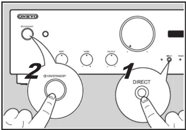
Resetting the unit (this resets the unit settings to the default)
Resetting the unit to the status at the time of shipment may solve the problem. If the unit is reset, your settings are restored to the default values. Be sure to note down your setting contents before performing the following operations.
- While the power is on, press ON/STANDBY while pressing DIRECT.
Power
Cannot turn on the unit
- Make sure that the power cord is properly plugged into the wall outlet.
- Unplug the power cord from the wall outlet, wait 5 seconds or more, then plug it in again.
The unit turns off unexpectedly
- The unit automatically enters standby mode when auto standby ( p20) is activated.
- A speaker cable may have shorted and the protective circuit function may have been activated. Make sure bare
speaker wires are not touching each other or the back panel of the unit, then turn the unit on again. If this unit does not turn on, immediately unplug the power cord from the wall outlet and contact your dealer.
- The protective circuit function may have been activated because the temperature of the unit rose abnormally. If this happens, then the power will continue to turn off after you have turned the unit on again. Make sure the unit has plenty of space for ventilation around it, wait for the unit to cool down sufficiently, and then try turning it on again.
- When switched to power amplifier mode, if the volume of the connected pre-amplifier is low, auto standby ( p20) may function and the power may automatically switch to standby. If this happens, you may be able to fix it by increasing the volume on the pre-amplifier.
WARNING: If smoke, smell or abnormal noise is produced by the unit, unplug the power cord from the wall outlet immediately and contact the dealer or customer support.
Audio
- Confirm that the connection between the output jack on the device and the input jack on this unit is correct.
Make sure that none of the connecting cables are bent, twisted, or damaged. - If MUTING is active, press MUTING on the remote controller to cancel. MUTING is active when the indicator for the selected input source is blinking.
While headphones are connected to the PHONES jack, no sound is output from the speakers or subwoofer.
Audio performance
Audio performance will be at its best about 10 to 30 minutes after the integrated amplifier has been turned on and had time to warm up.
- The sound quality can be affected by strong magnetic fields, such as those from a TV. Try moving any such devices away from the integrated amplifier.
- If you have any devices that emit high-intensity radio waves near the integrated amplifier, such as a cellular phone that's being used to make a call, the integrated amplifier may output noise.
- Install the integrated amplifier on a sturdy rack or shelf. Position it so that its weight is evenly dispersed on its four insulators. Do not install the integrated amplifier in a place with vibration or an unstable location.
No sound from a connected playback device
- Change the input selector on this unit to the position of the terminal to which the playback device is connected.
Only PCM audio is supported for input through the DIGITAL IN OPTICAL/COAXIAL jacks. Set the audio output on the playback device to output PCM.
A speaker produces no sound
- Make sure that the polarity of the speaker cables (+/-) is correct, and that no bare wires are in contact with the metal part of speaker terminals.
Make sure that the speaker cables have not shorted.
Make sure the speakers are connected correctly. ( 8)
Noise can be heard
- Using cable ties to bundle analog audio cables, power cords, speaker cables, etc. may degrade the audio performance, Do not bundle cords.
- An audio cable may be picking up interference. Try repositioning your cables.
Headphone output is intermittent or there's no sound
- The connection part may be dirty. Clean the headphones plug. See your headphones' instruction manual for cleaning information. Also, make sure that the headphones cable is not broken or damaged.
The RI function
The RI function isn't working properly
Make sure that the RI REMOTE CONTROL jacks are properly connected.
- A connection to the RI REMOTE CONTROL jack is not enough for the units to operate as a system. Connect the Digital cable or Analog audio cable properly. ( p11)
Remote Controller
- Make sure that the batteries are installed with the correct polarity.
- Install new batteries. Do not mix different types of batteries, or old and new batteries.
Make sure that the unit is not subjected to direct sunshine or inverter-type fluorescent lights. Relocate if necessary. - If the unit is installed in a rack or cabinet with colored-glass doors or if the doors are closed, the remote controller may not work reliably.
Cannot switch the input source
- If this unit is set to be used as a power amplifier, you will be unable to switch the input source or adjust the sound quality. Check the setting. ( p19)
Others
Strange noises can be heard from the unit
- If you have connected another unit to the same wall outlet as this unit, this noise may be an effect from the other unit. If the symptoms improve by unplugging the power cord of the other unit, use different wall outlets for this unit and the other unit.
Specifications
Amplifier (Audio) section
Rated Output Power (IEC)
2 ch × 60 W at 4 ohms, 20 Hz-20 kHz, 2 ch driven of
0.5% THD
2 ch × 76 W at 4 ohms, 1 kHz, 2 ch driven of 0.9% THD
2 ch × 30 W at 8 ohms, 20 Hz-20 kHz, 2 ch driven of
0.4% THD
2 ch × 52 W at 8 ohms, 1 kHz, 2 ch driven of 0.9% THD
Dynamic Power (^*)
(*)IEC60268-Short-term maximum output power
260 W (3 Ω, Front)
220 W (4 Ω, Front)
130 W (8Ω, Front)
Input Sensitivity and Impedance
200 mV/47 kΩ (LINE (RCA))
4 mV/47 kΩ (PHONO MM)
Rated RCA Output Voltage and Impedance
0.2 V/2.3 kΩ (LINE OUT)
1 V/500 Ω (SUBWOOFER PRE OUT)
Deviations from RIAA Equalizer
±0.5 dB (MM 20 Hz-20 kHz)
Phono Maximum Input Signal Voltage
70mV (MM 1 kHz, 0.5%)
Frequency Response
10 Hz - 100 kHz/ +1 dB, -3 dB (DIRECT)
Tone Control Characteristics
±10 dB, 100 Hz (BASS)
± 10 dB, 10kHz (TREBLE)
Signal to Noise Ratio
106 dB (IHF-A, LINE IN, SP OUT)
81 dB (IHF-A, PHONO IN, SP OUT)
Speaker Impedance
4Ω-16Ω
Supported impedance of Headphones
8Ω-600Ω
Headphones Frequency Response
30 Hz -100 kHz
General
Power Supply
AC 220-230 V, 50/60 Hz
Power Consumption
150W
0.2 W (Stand-by)
Dimensions (W× H× D)
435mm× 129mm× 330mm
17-1/8"×5-1/16"×13"
Weight
8.0 kg (17.6 lbs)
Audio Inputs
Digital
OPTICAL (D2)
Maximum Fs: 192 kHz
COAXIAL (D1)
Maximum Fs: 192 kHz
Analog
a Cable audio analogue
a Cable audio analogue
BASS (appareil principal unquipment)
TREBLE (appareil principal quinquement)
106 dB (IHF-A, LINE IN, SP OUT)
81 dB (IHF-A, PHONO IN, SP OUT)
a Cable RI, b Cable coaxial digital

CD
BASS (solo lainstitutional principal)
TREBLE (solo lainstitutional)
106 dB (IHF-A, LINE IN, SP OUT)
81 dB (IHF-A, PHONO IN, SP OUT)
18 Park Way, Upper Saddle River, N.J. 07458, U.S.A.
For Dealer, Service, Order and all other Business Inquiries:
Tel: 201-785-2600 Fax: 201-785-2650
http://www.us.onkyo.com/
For Product Support Team Only:
1-800-229-1687
http://www.us.onkyo.com/
Gutenbergstrasse 3, 82178 Puchheim, Germany
Tel: +49-8142-4401-0 Fax: +49-8142-4208-213
http://www.eu.onkyo.com/
Anteros Building, Odyssey Business Park, West End Road, South Ruislip, Middlesex,
HA4 6QQ United Kingdom
Tel: +44 (0)871-200-1996 Fax: +44 (0)871-200-1995
For Product Support only: +44 (0)208-836-3510
http://www.uk.onkyo.com/en/
6, Avenue de Marais F - 95816 Argenteuil Cedex FRANCE
For Product Support only: +33 969 368 138
Unit 1033, 10/F, Star House, No 3, Salisbury Road, Tsim Sha Tsui Kowloon, Hong Kong.
Tel: +852-2429-3118 Fax: +852-2428-9039
http://www.hk.onkyo.com/
302, Building 1, 20 North Chaling Rd., Xuhui District, Shanghai, China 200032,
Tel: +86-21-52131366 Fax: +86-21-52130396
http://www.cn.onkyo.com/
Please contact an Onkyo distributor referring to Onkyo SUPPORT site.
http://www.intl.onkyo.com/support/
The above-mentioned information is subject to change without prior notice. Visit the Onkyo web site for the latest update.
- INTEGRATED AMPLIFIER
- A-9130
- Instruction Manual
- Table of Contents What's in the box
- Before use
- Preparations
- Basic Operations
- Others
- Safety Information
- CAUTION:
- WARNING
- Precautions
- Operating Environment
- Important Notice
- CAUTION
- Power-Cord Caution
- For European models
- WEEE
- Part Names
- Front Panel
- Rear Panel
- Remote Controller
- Operating this unit
- Operating an Onkyo CD player
- Operating an Onkyo tuner, network audio player, or Rl dock
- Connections
- Connecting speakers
- (Note) Speaker Impedance
- Connect the Speaker Cables
- Connecting a Powered subwoofer
- Connecting players (DIGITAL IN connection)
- Connecting players (LINE IN connection)
- Connecting players (Turntable connection)
- Connecting with Onkyo RI Components
- Connection and Setup
- The RI function
- Auto Power On
- Direct change
- System off
- Remote controller operations
- Using this unit as a power amplifier
- Power Cord Hookup
- Setup
- Remote controller preparations
- Turn on the power of the unit
- Speaker impedance settings
- RI function settings
- Playback
- Switching input and adjusting the volume
- Subwoofer output settings
- Using the Direct Function
- Adjusting the sound quality and balance
- PHASE MATCHING BASS
- BASS (main unit only)
- TREBLE (main unit only)
- BALANCE (main unit only)
- Switching the unit to power amplifier mode
- Useful functions
- Setting auto standby
- Troubleshooting
- Before starting the procedure
- Resetting the unit (this resets the unit settings to the default)
- Power
- Cannot turn on the unit
- The unit turns off unexpectedly
- Audio
- Audio performance
- No sound from a connected playback device
- A speaker produces no sound
- Noise can be heard
- Headphone output is intermittent or there's no sound
- The RI function isn't working properly
- Cannot switch the input source
- Strange noises can be heard from the unit
- Specifications
- Amplifier (Audio) section
- General
- Audio Inputs
- BASS (appareil principal unquipment)
- BASS (solo lainstitutional principal)
- TREBLE (solo lainstitutional)
Brand : ONKYO
Model : A9130
Category : AV receiver