1680 - Saw DREMEL - Free user manual and instructions
Find the device manual for free 1680 DREMEL in PDF.

| Product Type | Scroll Saw |
| Brand | DREMEL |
| Model | 1680 |
| Table Dimensions | 406.4 mm (16 in) |
| Stroke Length | 19.5 mm |
| No-load Speed | 500-1600 strokes/min (variable) |
| Rated Current | 1.4 A |
| Supply Voltage | 120 V ~, 60 Hz |
| Cutting Capacity (0°) | 50.8 mm |
| Cutting Capacity (45°) | 25.4 mm |
| Blade Length | 127 mm (5 in) |
| Blade Type | Pin-end or bayonet |
| Table Tilt | 0° to 45° left/right |
| Main Features | Sawdust blower, integrated light, dust extraction connection, adjustable hold-down, quick-release tension lever, upper and lower blade holders, circuit breaker |
| Safety Devices | Mandatory grounding, lockable switch, eye protection and dust mask recommended |
| Maintenance and Cleaning | Lubricate arm bearings every 50 hours of use, replace carbon brushes (pair) if worn, clean internal dust, wax table for smooth sliding |
| Spare Parts and Repairability | Dremel replacement parts available (blades, brushes, bulb 25W max, etc.); repairs by qualified technician recommended |
| Warranty | Limited 2-year warranty (see manual for conditions) |
| Optional Accessories | Foot set (model 16500), various blades (pin-end, bayonet, spiral, metal, carbide) |
Frequently Asked Questions - 1680 DREMEL
User questions about 1680 DREMEL
0 question about this device. Answer the ones you know or ask your own.
Ask a new question about this device
Download the instructions for your Saw in PDF format for free! Find your manual 1680 - DREMEL and take your electronic device back in hand. On this page are published all the documents necessary for the use of your device. 1680 by DREMEL.
USER MANUAL 1680 DREMEL
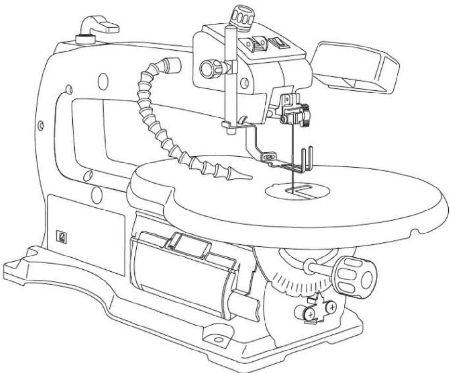
natural_image
Line drawing of a mechanical sewing machine with no visible text or symbols
Amperage rating 1.4 A
No load speed n 0 500-1,600/min
Throat 16"
Blade 5" Plain and pin-end
Blade stroke 3/4"
Cutting capacity 2" at 0°; 1" at 45°
assembly • operation • safety instructions
DREMEL P.O. Box 1468 Racine, Wisconsin
1-800-437-3635
http://www.dremel.com
General Safety Rules

"READ ALL INSTRUCTIONS" Failure to follow the safety rules listed below and other basic safety precautions may result in serious personal injury.
Work Area
KEEP CHILDREN AWAY
Do not let visitors contact tool or extension cord. All visitors should be kept away from work area.
KEEP WORK AREAS CLEAN
Cluttered areas and benches invite accidents.
MAKE WORKSHOP CHILD-PROOF
With padlocks, master switches.
AVOID DANGEROUS ENVIRONMENTS
Don't use power tools in damp or wet locations. Keep work area well lit. Do not expose power tools to rain. Do not use the tool in the presence of flammable liquids or gases.
Personal Safety
Read and understand the owner's manual and labels affixed to the tool. Learn its application and limitations as well as the specific potential hazards peculiar to this tool.
DON'T OVERREACH
Keep proper footing and balance at all times.
STAY ALERT
Watch what you are doing. Use common sense. Do not operate tool when you are tired. Do not operate while under medication or while using alcohol or other drugs.
DRESS PROPERLY
Do not wear loose clothing or jewelry. They can be caught in moving parts. Rubber gloves and non-skid footwear are recommended when working outdoors. Wear protective hair covering to contain long hair.
USE SAFETY GLASSES
Also face or dust mask if cutting operation is dusty, and ear plugs during extended periods of operation.
Everyday eyeglasses have only impact resistant lenses, they are NOT safety glasses.
Prevent body contact with grounded surfaces. For example: pipes, radiators, ranges, refrigerator enclosures.
DISCONNECT TOOLS FROM POWER SOURCE
When not in use, before servicing, when changing blades, bits, cutters, etc.
KEEP GUARDS IN PLACE
In working order, and in proper adjustment and alignment.
REMOVE ADJUSTING KEYS AND WRENCHES
Form the habit of checking to see that keys and adjusting wrenches are removed from tool before turning it on.
AVOID ACCIDENTAL STARTING
Make sure the switch is in the "OFF" position before plugging in tool.
GROUND ALL TOOLS
This tool is equipped with an approved 3-conductor cord and a 3 prong grounding type plug to fit the proper grounding type receptacle. The green conductor in the cord is the grounding wire. Never connect the green wire to a live terminal.
NEVER STAND ON TOOL OR ITS STAND
Serious injury could occur if the tool is tipped or if the cutting tool is accidentally contacted. Do not store materials on or near the tool such that it is necessary to stand on the tool or its stand to reach them.
CHECK DAMAGED PARTS
Before further use of the tool, a guard or other part that is damaged should be carefully checked to ensure that it will operate properly and perform its intended function. Check for alignment of moving parts, mounting, and any other conditions that may affect its operation. A guard or other part that is damaged should be properly replaced.

All repairs, electrical or mechanical, should be attempted only by trained repairmen.
Contact the nearest Dremel Service Center, Authorized Dremel Service Station or other competent repair service.

Use only Dremel replacement parts; any others may create a hazard.

The use of any other accessories not specified in the current Dremel catalog, may cre-
"SAVE THESE INSTRUCTIONS"
Additional Safety Rules
Tool Use
DON'T FORCE TOOL
It will do the job better and safer at the rate for which it was designed.
USE THE RIGHT TOOL
Don't force a small tool or attachment to do the job of a heavy duty tool. Don't used tool for purpose not intended—for example, don't use a circular saw for cutting tree limbs or logs.
SECURE WORK
Use clamps or a vise to hold work when practical. It's safer than using your hand and it frees both hands to operate the tool.
NEVER LEAVE TOOL RUNNING UNATTENDED
Turn power off. Don't leave tool until it comes to a complete stop.
Tool Care
DO NOT ALTER OR MISUSE TOOL
These tools are precision built. Any alteration or modification not specified is misuse and may result in dangerous conditions.
AVOID GASEOUS AREAS
Do not operate electric tools in a gaseous or explosive atmosphere. Motors in these tools normally spark, and may result in a dangerous condition.
MAINTAIN TOOLS WITH CARE
Keep tools sharp and clean for better and safer performance. Follow instructions for lubricating and changing accessories. Inspect tool cords periodically and if damaged, have repaired by authorized service facility. Inspect extension cords periodically and replace if damaged. Keep handles dry, clean and free from oil and grease.
WARNING
Before connecting the tool to a power source (receptacle, outlet, etc.), be sure
voltage supplied is the same as that specified on the nameplate of the tool. A power source with a voltage greater than that specified for the tool can result in serious injury to the user, as well as damage to the tool. If in doubt, DO NOT PLUG IN THE TOOL. Using a power source with a voltage less than the nameplate rating is harmful to the motor.
WARNING
For your own safety, do not operate your Scroll Saw until it is completely assembled
and installed according to the instructions...and until you have read and understood the following:
- General Safety Rules....2-4
- Motor Specifications and Electrical Requirements 5
- Getting to Know Your Scroll Saw ....8-9
- Operating Adjustments .....10
- Basic Scroll Saw Operations .....11-14
- Mounting the Scroll Saw....15-16
- Maintaining Your Scroll Saw ....17
8. STABILITY OF SAW
Your Scroll Saw must be bolted securely to a stand or workbench. In addition, if there is any tendency for the Scroll Saw to tip over or move during certain operations, such as cutting long, heavy boards, bolt your Scroll Saw stand or workbench to the floor.
9. LOCATION
This Scroll Saw is intended for indoor use only.
- PROTECTION: Eyes, hands, face, ears and body.
WARNING
TO AVOID BEING PULLED INTO THE BLADE—
DO NOT WEAR: Loose Fitting Gloves
Necktie
Loose Clothing
Jewelry
DO: TIE BACK LONG HAIR
ROLL LONG SLEEVES ABOVE ELBOWS
a. If any part of your saw is missing, malfunctioning, has been damaged or broken . . . such as the motor switch, or other operating control, a safety device or the power cord...cease operating immediately until the particular part is properly repaired or replaced.
b. Do not cut piece too small to hold by hand. HINT: When making a very small cut out, always secure the workpiece to a scrap piece of plywood with double-faced tape. This way, the work is supported and your fingers are away from the blade.
c. Never turn your Scroll Saw on before clearing the table of all objects (tools, scraps of wood, etc.) except for the workpiece and related feed or support devices for the operation planned.
Additional Safety Rules
d. Avoid awkward hand positions where a sudden slip could cause a hand to move into the blade.
- ALWAYS adjust the drop foot to just clear the workpiece to protect the operator, keep blade breakage to a minimum and provide maximum support for blade.
• Always adjust blade tension correctly.
- The Scroll Saw should cut on the down stroke. Always make sure blade teeth are oriented downward toward table.
- When cutting a large piece of material, make sure it is supported at table height.
- Hold the work firmly against the table.
- Do not feed the material too fast while cutting. Only feed the material fast enough so that the blade will cut. Keep fingers away from the blade.
- Use caution when cutting off material which is irregular in cross section, it could pinch the blade before the cut is completed. A piece of molding, for example, must lay flat on the table and not be permitted to rock while being cut.
- Use caution when cutting off round material such as dowel rods or tubing. They have a tendency to roll while being cut, causing the blade to "bite".
e. Never leave the Scroll Saw running unattended. Turn the saw OFF, make sure the saw has come to a complete stop, and then remove plug from power supply before leaving the work area.
f. Do not perform layout, assembly or setup work on the table while the cutting tool is operating.
g. Turn saw off and remove plug from power supply outlet before installing or removing an accessory attachment.
h. Access Door must be closed before operation.
i. Quick Release Tension Lever should be in down position before operating.
11. THINK SAFETY
SAFETY IS A COMBINATION OF OPERATOR COMMON SENSE AND ALERTNESS AT ALL TIMES WHEN THE SCROLL SAW IS BEING USED.

Do not allow familiarity (gained from frequent use of your Scroll Saw) to become
commonplace. Always remember that a careless fraction of a second is sufficient to inflict severe injury.

The operation of any power tool can result in foreign objects being thrown into the eyes, which can result in severe eye damage. Always wear safety goggles that comply with ANSI Z87.1 before commencing power tool operation.

Some dust created by power sanding, sawing, grinding, drilling, and other construction activities contains chemicals known to cause cancer, birth defects or other reproductive harm. Some examples of these chemicals are:
- Lead from lead-based paints,
- Crystalline silica from bricks and cement and other masonry products, and
- Arsenic and chromium from chemically treated lumber.
Your risk from these exposures varies, depending on how often you do this type of work. To reduce your exposure to these chemicals: work in a well ventilated area, and work with approved safety equipment, such as those dust masks that are specially designed to filter out microscopic particles.
NOTE AND FOLLOW THE SAFETY WARNINGS AND INSTRUCTIONS THAT APPEAR ON THE PANEL ON SCROLL SAW HOUSING:

For Your Own Safety - Read and Understand
owner's manual before operating saw. Unplug saw before changing blade, adjusting, moving, or storing it. Securely fasten tool to a stable platform or workbench. Know how to shut off tool in an emergency. Blade teeth must point down, maintain proper tension of blade and adjust the drop foot height. Wait for blade to stop before removing jammed or cut-off workpiece. Wear eye protection and dust mask. Do not expose to rain or use in damp locations. Grounding required.
MOD. 1680
F013 1680 02


120 VOLTS AC 50-60 Hz. 1.4 AMPS 500 -1600 SPM
LISTED TOOL 37J2
LR 59053
DREMEL RACINE, WI. U.S.A. 1-800-437-3635 www.dremel.com Made in Taiwan

Motor Specifications and Electrical Requirements
Motor Specifications
In the event of a malfunction or breakdown, grounding provides a path of least resistance for electric current to reduce the risk of electric shock.
This Scroll Saw is designed to use a Variable Speed RPM motor. It is wired for operation on 110-120 volts, 60 Hz. alternating current. Before connecting the motor cord to power source, make certain the switch is in the "OFF" position and be sure the electric current is of the same characteristics as stamped on the nameplate.
Connection To A Power Source
This machine must be grounded while in use to protect the operator from electric shock.
Plug power cord into a 110-120V properly grounded type outlet protected by a 15-amp dual element time delay fuse or circuit breaker.
Not all outlets are properly grounded. If you are not sure that your outlet, as pictured below, is properly grounded; have it checked by a qualified electrician.
DANGER
To avoid electric shock, do not touch the metal prongs on the plug when installing or plug to or from the outlet.
DANGER
Failure to properly ground this power tool can cause electrocution or serious shock, partic-
ularly when used near metal plumbing or other metal objects. If shocked, your reaction could cause your hands to hit the tool.
WARNING
If power cord is worn, cut or damaged in any way, have it replaced immediately to avoid
shock or fire hazard.
Your unit is for use on 120 volts; it has a plug that looks like the one below.

This power tool is equipped with a 3-conductor cord and grounding type plug, approved by Underwriters Laboratories and the Canadian Standards Association. The ground conductor has a green jacket with or without yellow stripes and is attached to the tool housing at one end and to the ground prong in the attachment plug at the other end.
This plug requires a mating 3-conductor grounded type outlet as shown. It must be grounded in accordance with all local codes and ordinances.
If the outlet you are planning to use for this power tool is of the two-prong type, DO NOT REMOVE OR ALTER THE GROUNDING PRONG IN ANY MANNER. Have a qualified electrician replace the TWO-prong outlet with a properly grounded THREE prong outlet.
Improper connection of the equipment-grounding conductor can result in a risk of electric shock. If repair or replacement of the electric cord or plug is necessary, do not connect the equipment-grounding conductor to a live terminal.
Check with a qualified electrician or service personnel if the grounding instructions are not completely understood, or if in doubt as to whether the tool is properly grounded.
The temporary adapter should be used only until a properly grounded outlet can be installed by a qualified electrician.
WARNING
The green grounding lug extending from the adapter must be connected to a permanent
ground such as a properly grounded outlet box.

NOTE: The adapter illustrated is for use only if you already have a properly grounded 2-prong receptacle. Adapter is not allowed in Canada by the Canadian Electrical Code. Always use proper extension cord.
The use of any extension cord will cause some loss of power. To keep this to a minimum and to prevent overheating and motor burn-out, use the table below to determine the minimum wire size (A.W.G.) extension cord. Use only 3-wire extension cords which have 3-prong grounding type plugs and 3-pole receptacles which accept the tool's plug. Make sure your extension cord is in good condition.
Extension Cord Length Wire Size A.W.G.
0-25 Feet 18
26-50 Feet 16
51-100 Feet 16
"SAVE THESE INSTRUCTIONS"
Table of Contents
General Safety Rules....2
Additional Safety Rules 3-4
Motor Specifications and Electrical Requirements ....5
Connection to a Power Source....5
Unpacking and Checking Contents ....7
Table of Loose Parts....7
Glossary of Terms....8
Getting to Know Your Scroll Saw 8-9
Operating Adjustments ....10
Setting the Table for Horizontal or Bevel Cutting......10
Aligning the Degree Scale Pointer ....10
Basic Scroll Saw Operations ......11-14
Removing and Installing Pin-End Blades 12
Removing and Installing Plain-End Blades .....12
Adjusting the Lamp....13
Replacing the Bulb 13
On/Off Switch 13
Variable Speed Switch 13
Reset Button 13
Making Interior Scroll Cuts Pin-End Blades and Plain-End Blades....14
Mounting the Scroll Saw....15-16
Mounting the Scroll Saw to a Bench ....15
Mounting the Scroll Saw to Plywood ....16
Attaching Scroll Saw to Leg Set....16
Maintaining Your Scroll Saw ....17
Lubrication 17
Recommended Accessories ....18
Trouble Shooting....19
Dremel Limited Warranty 22
Service Parts List....61-64
Unpacking and Checking Contents

WARNING
To avoid injury from unexpected starting or electrical shock, always remove plug from when tool is not in use.
Model 1680 Motorized Scroll Saw is shipped complete in one carton.
- Unpacking and Checking Contents. Separate all "loose parts" from packing materials and check each item with the "Table of Loose Parts" to make sure all items are accounted for before discarding any packing material.

WARNING
If any parts are missing, do not attempt to operate Scroll Saw, plug in the power the switch on until the missing parts are installed correctly.
natural_image
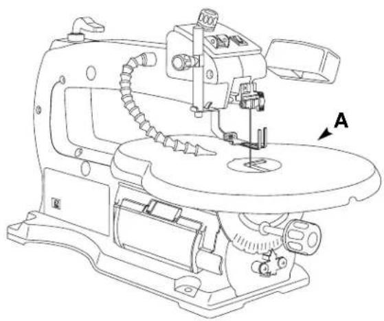
Line drawing of a sewing machine with labeled component A (no text or symbols beyond label)Table of Loose Parts
Item Description Qty.
A 16" Scroll Saw ....1
B Owner's Manual ....1
C Loose Parts Bag (containing)....1
Allen Wrench (3 mm) 1
Allen Wrench (5 mm) 1
Blades 11
NOTE: Hardware to mount this Scroll Saw to a bench or leg set is NOT supplied. See mounting instructions on Page 15-16 for recommended hardware size.
To remove protective coating from the table surface, moisten a soft cloth with kerosene and wipe off coating. Do not use acetone, gasoline or lacquer thinner for this purpose.
After removing protective coating, If you wish, you may apply a coat of paste wax to the table to allow the workpiece to slide easily across the table surface and deter rust. Wipe the table thoroughly with a clean dry cloth.

natural_image
Simple line drawing of a blank rectangular sheet with a downward arrow labeled 'B' pointing to the top edge (no text or symbols on the sheet itself)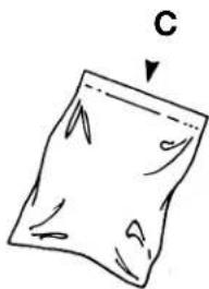
natural_image
Simple line drawing of a folded paper or sheet with a label 'C' pointing downward (no text or symbols on the sheet itself)Tools Needed
PHILLIPS SCREWDRIVER

WRENCHES
7/16 in.
natural_image
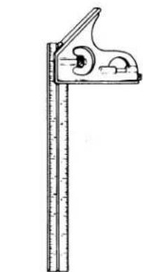
Illustration of a ruler measuring an object, showing measurement markings and scale (no text or symbols)COMBINATION
SQUARE
COMBINATION SQUARE MUST BE TRUE
Check its accuracy as illustrated below.
DRAW LIGHT LINE ON BOARD ALONG THIS EDGE
STRAIGHT EDGE OF BOARD 3/4" THICK-
THIS EDGE MUST BE PERFECTLY STRAIGHT

SHOULD BE NO GAP OR OVERLAP WHEN SQUARE IS FLIPPED OVER IN DOTTED POSITION
Glossary of Terms
KERF The slot cut by the blade.
LEADING EDGE
The edge of the workpiece which is pushed into the blade first.
SAWBLADE PATH
The area of the workpiece directly in line with and moving toward the sawblade edge.
BLADE TOOTH SET
The distance that the edge of the sawblade tooth is bent (onset) outward from the side of the blade.
TRAILING EDGE
The workpiece edge last cut by the sawblade.
WORKPIECE
The item on which the cutting operation is being performed.
Getting to Know Your Scroll Saw
This versatile Scroll Saw is great for making toys, puzzles, games, fretwork, and jewelry. Because of its cutting capacity, it is a handy do-it-yourself tool. It cuts wood up to 2 inches thick as well as plastics and non-ferrous metals.
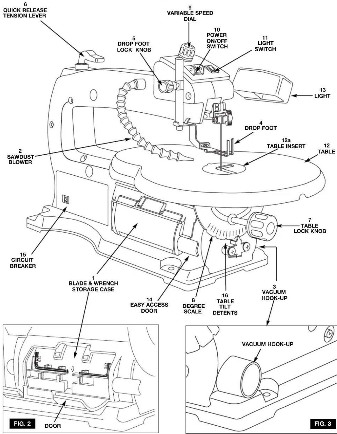
1. BLADE & WRENCH STORAGE CASE
Your Scroll Saw is equipped with a blade storage area located on the easy access door of the saw. The blade storage area conveniently stores your allen wrenches, and both Pin and Plain end blades.
2. SAWDUST BLOWER
Keeps workpiece clean for more accurate scroll cuts. For best results, always direct air flow from blower tube at blade and workpiece. To adjust, simply bend to desired position.
3. VACUUM HOOK-UP
Your Scroll Saw is equipped with a vacuum hook-up. This feature will allow you to attach any 1-1/4" vacuum hose into the hole provided for convenient sawdust removal.
4. DROP FOOT
The foot should always be lowered until it just rests on top of the workpiece to prevent workpiece from lifting, but not so much that the workpiece drags.
5. DROP FOOT LOCK KNOB
Allows you to raise or lower the foot and lock it at desired heights.
Allows you to quickly loosen, or tighten the blade to it's original tension with lever action.
7. TABLE LOCK KNOB
Allows you to tilt the table and lock it at desired angle up to 45 degrees to the right or left.
8. DEGREE SCALE
Shows the degree the table is tilted.
9. VARIABLE SPEED DIAL
Your Scroll Saw is equipped with a variable speed dial for greater versatility.
10. POWER ON/OFF SWITCH
Has holes provided by the switch for a lock (not included). THIS FEATURE IS INTENDED TO PREVENT UNAUTHOURIZED AND POSSIBLY HAZARDOUS USE BY CHILDREN AND OTHERS. To turn saw on, push power switch to the "on" position; to turn saw off, push power switch to the "off" position.
11. LIGHT SWITCH
To turn light on, push light switch to the "on" position; to turn light off, push light switch to the "off" position.
12. TABLE
Provide working surface to support workpiece.
12.a TABLE INSERT
Should always be in place and flush with table during cutting operation.
13. LIGHT
Illuminates the workpiece.
14. EASY ACCESS DOOR
Allows easy access to lower blade holder when changing blades.
15. CIRCUIT BREAKER
Protects motor from from overheating and damage.
16. TABLE TILT DETENTS
Automatically stops the table to the right or left at 0, 15, 30, and 45 degree increments.
17. ALLEN WRENCHES
Convenient wrenches, assists in making blade changes and adjustments if desired.
Getting to Know Your Scroll Saw
FIG. 1
9.
Operating Adjustments
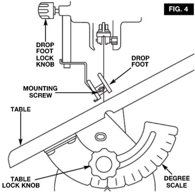
Setting the Table for Horizontal or Bevel Cutting
- Loosen the table lock knob, and the saw table can be tilted to the right or left and locked at any angle from 0 degree horizontal cutting position up to 45 degrees for bevel cutting (Fig. 4). Your tool also features table tilt den- tents which automatically stops the table to the right or left every 15 degrees.
- A degree scale is also provided under the work table as a convenient reference for setting the approximate table angle for bevel cutting. When greater precision is required, make practice cuts and adjust the table as necessary for your requirements.
Adjusting the hold down clamp
The hold down clamp should always rest just above the workpiece to help prevent the workpiece from lifting from the table.
- Hold the drop foot, loosen the drop foot lock knob and lower by hand until it just rests above the workpiece surface, and securely tighten the drop foot lock knob.
- When cutting with the table angled, adjust drop foot so it's parallel to the table. To adjust, loosen screw with the allen wrench provided, turn foot to correct angle, tighten screw.
Always make sure the blade does not contact either side of the drop foot, or the table opening.
NOTE: When cutting at extreme angles, the drop foot should be lifted off the workpiece, as it will impede cutting. Hold the workpiece against the table. The drop foot may be disassembled when thick materials are cut at extreme angles.
Aligning the Degree Scale Pointer
The table is factory set to 0^ . If further adjustments are necessary, please follow the instructions below:
- Loosen the table lock knob and move the table until it is 90 degree to the blade.
- With the wrench provided remove the drop foot assembly, mounting screw, and washer, and move it out of the way. Place a small square on the table next to the blade as shown in (Fig. 5) to check if the table is 90° to the blade. If no adjustment is required, replace the drop foot assembly, washer and screw.
If adjustment is necessary. Loosen, but don't remove the two screws holding the pointer. With the steel ball centered in the 0^ detent, slide the pointer left or right until the blade is parallel to the square.
4. Tighten the table lock knob, both screws, and replace drop foot, washers and screw. Remember, the degree scale is a convenient guide but should not be relied upon for precision. Make practice cuts in scrap wood to determine if your angle setting is correct.
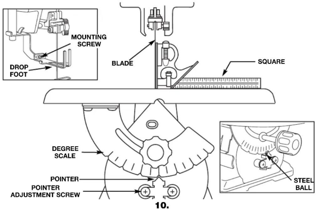
FIG. 5
Basic Scroll Saw Operations
Follow these instructions for operating your Scroll Saw to get the best results and to minimize the likelihood of personal injury.

WARNING
ALWAYS OBSERVE THE SAFETY PRECAUTIONS HERE AND ON PAGES 2, 3, 4,
AND 5.
- Protection: Eyes, Hands, Face, Ears and Body

WARNING
TO AVOID BEING PULLED INTO THE BLADE—
DO NOT WEAR: Loose Fitting Gloves Necktie Loose Clothing Jewelry
DO: TIE BACK LONG HAIR ROLL LONG SLEEVES ABOVE ELBOWS
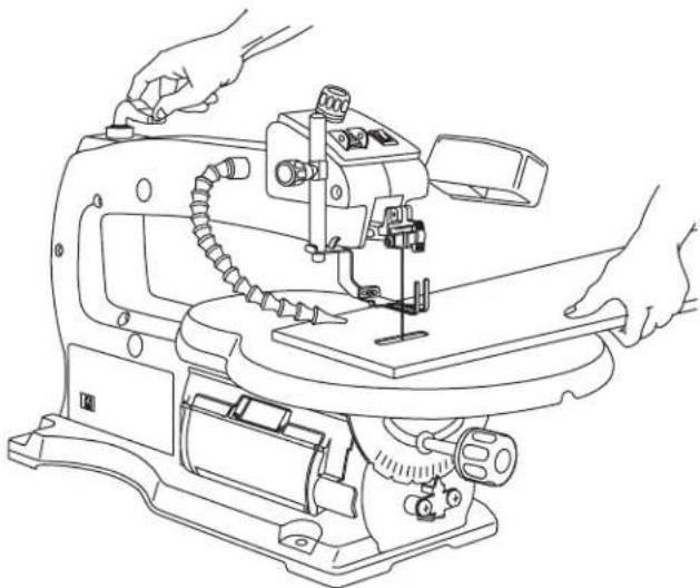
- The saw does not cut wood by itself. You allow the saw to cut wood by guiding the wood into the blade as it moves.
- The blade teeth cut ONLY on the down stroke.
- The drop foot should always be lowered until it just rests on top of the workpiece.
- You must feed the wood into the blade slowly because the teeth of the blade are very small and they can only remove wood when they are on the down stroke. The blade will flex backwards when applying feed pressure. Too much feed pressure will cause blade breakage.
-
There is a learning curve for each person who wants to use this saw. During that period of time it is expected that some blades will break until you learn how to use the saw and receive the greatest benefit from the blades.
-
Best results are achieved when cutting wood less than one inch thick.
- When cutting wood thicker than one inch the user must feed the wood very slowly into the blade, increase blade tension and take extra care not to bend or twist the blade while cutting in order to maximize blade life.
- Teeth on Scroll Saw blades wear out and as such must be replaced frequently for best cutting results. Scroll Saw blades generally stay sharp for 1/2 hour to 2 hours of cutting.
- To get accurate cuts be prepared to compensate for the blade's tendency to follow the wood grain as you are cutting.
- When choosing a blade to use with your Scroll Saw consider the following carefully:
- Choose a blade that allows at least three (3) teeth to be in contact with the workpiece at all times.
- Very fine, narrow blades should be used to scroll cut in thin wood (1/4 inch thick or less).
- To cut thicker wood, use wider blades with fewer teeth per inch.
- Most blade packages state the size or thickness of wood which that blade is intended to cut, and the radius (size of curve) which can be cut with that blade.
- Wider blades can't cut curves as tight or small as thinner blades.
- This saw uses 5 inch long, Pin or Plain-End type blades only (See Accessories on page 18).
- Blades wear faster when (1) cutting plywood, which is very abrasive, (2) when sawing wood which is thicker than the 3/4 inch blade stroke, and (3) when sawing hardwood, or when side pressure is placed on the blade.
Basic Scroll Saw Operations
Blades
Your new Scroll Saw accepts 5 inch Pin-End blades or 5 inch Plain-End blades (See Accessories on page 18).

WARNING
To prevent personal injury always disconnect the plug from power source before changing
blades or making adjustments.
Removing and Installing Pin-End Blades
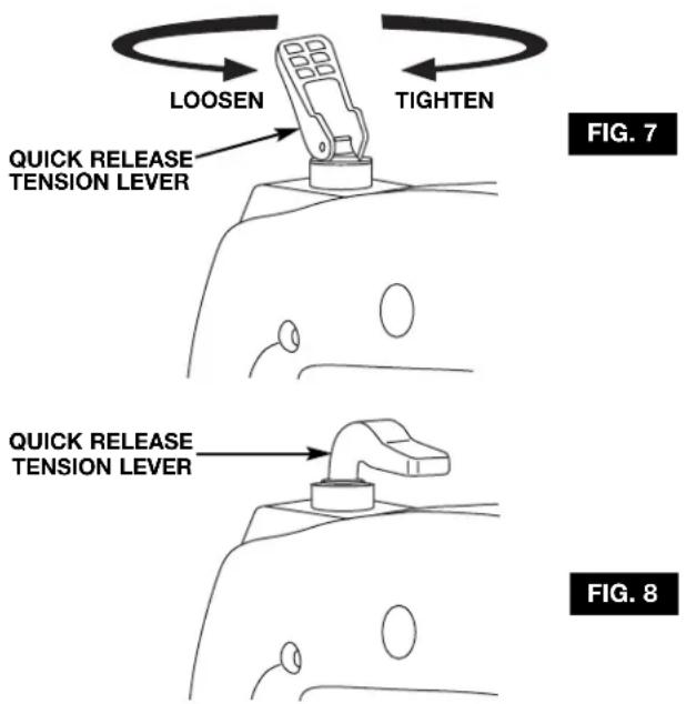
- Release blade tension by lifting up the Quick Release Tension Lever (Fig. 7).
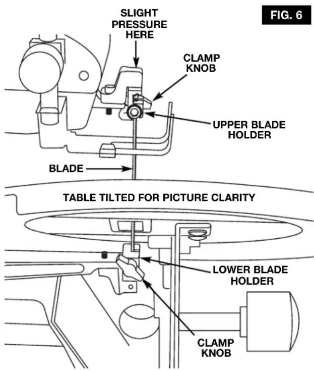
- Open easy access door and loosen the blade clamping knob on the upper and lower blade holders. Remove blade from the upper and lower blade holders by pulling forward on blade and then lifting the blade through the access hole in the table. Slight downward pressure against the upper holder may be helpful when removing blade from upper holder.
- Look at the blade holders closely and notice the blade slots and pin recesses in the blade holders.
NOTE: In order to cut, and avoid uncontrollable lifting of the workpiece, the teeth of the blade used on the Scroll Saw should always point downward as shown in (Fig. 6) when installed.
- Install the blade by inserting one end of the blade through the access hole in the table and hook the blade pin in the pin recess in the lower blade holder. Slide the top blade pin into the pin recess of the upper blade holder. You may need to press down lightly on the upper blade holder to install the blade.
- Check to see that the pins are properly located in the blade holders.
Removing and Installing Plain-End Blades
- Release blade tension by lifting up the Quick Release Tension Lever (Fig. 7).
- Open easy access door and loosen the blade clamping knob on the upper and lower blade holders. Remove blade from the upper and lower blade holders by pulling forward on blade and then lifting the blade through the access hole in the table.
- Install the blade by inserting one end of the blade through the access hole in the table and centering the blade in the blade slot in the upper and lower blade holders. To secure the blade securely tighten the clamping knob on the upper and lower holders. If desired, the allen wrench provided can assist in securely tightening the blade into the upper and lower blade holders (Fig. 6).
Blade Tension
To tension blade, move Quick Release Tension Lever to “down” position. As the lever is lowered, tension will be applied to the blade (Fig. 8).
ATTENTION: Moving the lever downward should require moderate, steady pressure only. If heavy pressure is needed, the blade is too tight. Loosen tension by rotating the Quick Release Tension Lever counterclockwise 1-2 turns, then reset the tension lever to the "down" position. If the tension lever is in the "down" position and the blade is too loose, you can increase tension by leaving the tension lever "down" and rotating it clockwise just until you feel the slack in the blade removed. Then turn the tension lever ONE full turn clockwise. This amount of blade pressure should do well for most cutting operations and blades (Fig. 7).
When the blade tension has been properly adjusted, you should be able to lift up the Quick Release Tension Lever, remove and install the blade, lower the lever and return the original blade tension.
NOTE: It may be necessary to re-adjust the tension lever when using different types of blades.
Basic Scroll Saw Operations
Adjusting the Lamp
- Position the lamp as needed to illuminate the workpiece.
- Loosen lock knob, slide lamp to desired position and tighten lock knob (Fig. 9).
Note: Lamp shade angle is fixed and cannot be adjusted.
Replacing the Bulb
- Use only a (25 watt maximum), candelabra base bulb. Turn the light switch off and unplug the saw.
- Remove the shade screw and the outer shade cover.
- Slide the inner shade off the bulb socket.
- Replace bulb and reassemble the shades (Fig. 9).
Note: Additional bulbs are available through Customer Service.
ON/OFF Switch
- To turn power ON or OFF push the power switch (Fig. 10).
Variable Speed Switch
- Your saw is equipped with a variable speed dial.
The blade stroke rate may be adjusted by simply rotating the dial (Fig. 10).
To increase speed, rotate dial clockwise.
To reduce speed, rotate dial counterclockwise.
Reset Button
Your saw features a reset button that protects the motor from overheating and damage (Fig. 11).
- If the switch pops, turn the power ON/Off switch to the off position.
- Unplug the cord from the power source and allow the saw to cool down.
- Return reset button to its original position.
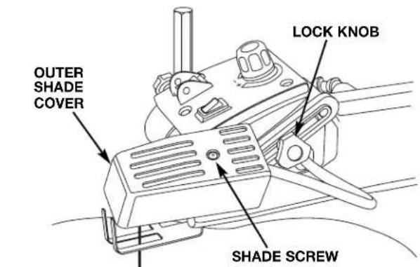
FIG. 9
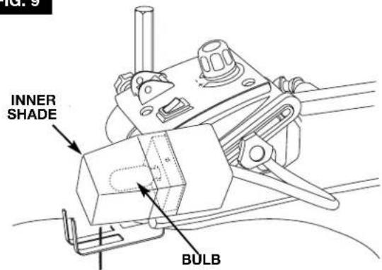

FIG. 11

Basic Scroll Saw Operations
Making Interior Scroll Cuts
(Pin-End Blades and Plain-End Blades)

WARNING
TO AVOID ACCIDENTAL STARTING, ALWAYS TURN SWITCH "OFF" AND
REMOVE PLUG FROM POWER SOURCE BEFORE REMOVING OR REPLACING THE BLADE.
A main benefit of this saw is the ability to perform intricate interior cuts quickly and easily. This is best accomplished using the Quick Release Tension Lever. Simply follow these steps (Fig. 12):
- Drill appropriate sized pilot hole in work piece.
- Release Quick Release Tension Lever.
3 Remove the blade from the upper blade holder as explained on page 12 Removing and Installing (Pin-End) or (Plain-End) blades. - Thread blade through pilot hole from underneath the workpiece. If needed, remove the table insert. This will allow the blade to fall forward for more clearance between the workpiece and the upper arm housing. Reinstall the blade in the upper blade holder.
- Retension blade by pulling tension lever down.
- Lower drop foot until it just rests on top of the workpiece and you're ready to begin cutting.
- When finished making the interior scroll cuts simply remove the blade from the blade holders, as described on page 12 Removing and Installing (Pin-End) or (Plain-End) blades, and remove the board from the table.
FIG. 12
natural_image
Line drawing of a sewing machine with hands operating it (no text or symbols)Mounting the Scroll Saw
Mounting the Scroll Saw to a Bench
- The Scroll Saw should be fastened securely to a firm supporting surface such as a stand or workbench, using the four mounting holes.
Note: When mounting this saw to a workbench, a solid bench is preferable to a plywood bench where noise and vibration will be more noticeable.
We recommend to reduce noise and vibration, that a soft foam pad be placed between your Scroll Saw and workbench. (Not Supplied)
Quantity Description
1 Soft foam pad, such as carpet padding, 24"x12"x1/2"
- When mounting the Scroll Saw to a workbench, holes should be drilled through the foam pad or carpet and mounting surface of the workbench using the dimensions illustrated in Figure 13.
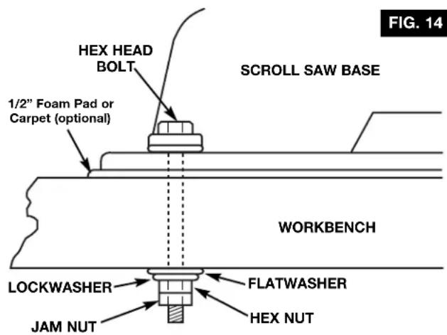
Each of the four mounting holes should be bolted securely using no less than 1/4" hex bolts, flat washers, lock washers, and nuts. We recommend:
Quantity Description
4 Hex Head Bolts, 1/4"-20 x 1/4"-20 x Length Required 4 Flat Washers, 9/32" I.D. 4 Lockwasher, 9/32" I.D. 8 Hex Nuts, 1/4"-20 (Hardware not supplied)
A. Locate and mark where the Scroll Saw is to be mounted.
B. Drill the four 5/16" holes through the workbench.
C. Place the Scroll Saw on the workbench aligning holes in the base with the holes drilled in the workbench. Insert all four (4) screws and tighten.
Note: Do NOT overtighten mounting bolts - leave some cushion in the foam pad for absorbing noise and vibration.
ATTENTION: When inserting the front right hex head bolt, it will be necessary to insert the hex head bolt from the bottom side of the workbench, and secure with hex nut from the top side of Scroll Saw Base.
Example of mounting this Scroll Saw to workbench (Fig. 14).
FIG. 13

Mounting the Scroll Saw
Mounting the Scroll Saw to Plywood
An alternative method of securing your Scroll Saw is to fasten the Scroll Saw base to a mounting board 18" x 24". Any good grade of plywood with a 3/4" minimum thickness is recommended. Follow the instructions for "Mounting the Scroll Saw to a Bench", substituting the 18" x 24" board for the workbench and using 1/4"-20 Flat Head Screws for the Hex Screws (Fig.15).
Note: For proper stability, holes must be counter sunk so screw heads are flush with the bottom surface of the supporting board.
Securely clamp board to workbench using two or more "C" Clamps.
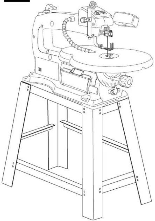
Attaching the Scroll Saw to Leg Set (Available as Accessory)
If you prefer to mount your Scroll Saw to a leg set we recommend the leg set for benchtop tools which is available through Dremel. The model number is 16500. This leg set is an optional accessory and instructions to mount the Scroll Saw to this leg set are included in the package (Fig. 16).
FIG. 15

FIG. 16
natural_image
Line drawing of a manual machine with handle and workpiece (no text or symbols)Maintaining Your Scroll Saw
Maintenance
WARNING
For your own safety, turn power switch "OFF" and remove plug from the power source outlet before maintaining or lubricating your Scroll Saw.
GENERAL
Frequently blow out any dust that may accumulate inside the motor.
An occasional coat of paste wax on the work table will allow materials being cut to glide smoothly across the work surface and deters rust.
CAUTION
Certain cleaning agents and solvents damage plastic parts. Including: gasoline, carbon tetrachloride, chlorinated cleaning solvents, ammonia and household detergents that contain ammonia. Avoiding use of these and other types of cleaning agents minimizes the probability of damage.
WARNING
To avoid shock or fire hazard, if the power cord is worn or cut, or damaged in any way, have it replaced immediately.
WARNING
All repairs, electrical or mechanical, should be attempted only by trained repairmen. Contact the nearest Dremel Factory Service Center, or other competent repair service. Use only Dremel replacement parts, any others may create a hazard.
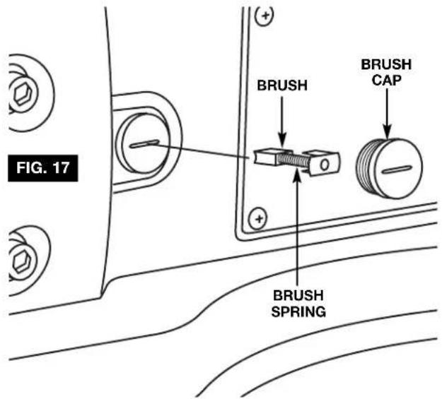
Carbon Brushes
The brushes and commutator in your tool have been engineered for many hours of dependable service. To maintain peak efficiency of the motor, we recommend every two to six months the brushes be examined. Only genuine Dremel replacement brushes specially designed for your tool should be used.
The brushes should be inspected frequently when tools are used continuously. If your tool runs sporadically, loses
power, makes unusual noises or runs at a reduced speed, check the brushes. To continue using the tool in this condition will permanently damage your tool.
With the cord unplugged, remove the brush caps one at a time with a small screwdriver by rotating cap counter-clockwise and check each brush (Fig. 17).
If the brush is less than 1/8" long and the end surface of the brush that contacts the commutator is rough and/or pitted, they should be replaced. Check both brushes. Usually the brushes will not wear out simultaneously. If one brush is worn out, replace both brushes. Make sure the brushes are installed as illustrated. The curved surface of the brush must match the curvature of the commutator.
After replacing brushes the tool should be run at no-load; place it on a clean surface and run it freely for 5 minutes before loading (or using) the tool. This will allow the brushes to "seat" properly and will give you more hours of life from each set of brushes. This will also extend the total life of your tool since the commutator surface will "wear" longer.
Lubrication
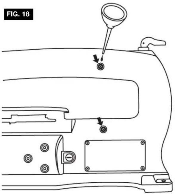
ARM BEARINGS
Lubricate the arm bearings with oil after 10 hours of use. Re-oil after every 50 hours of use or whenever there is a squeak coming from the bearings.
TO LUBRICATE
- Turn saw on its side (Fig. 18).
- Remove rubber plug to expose bronze bearing.
- Squirt a generous amount of SAE 20 oil around the shaft end and bronze bearing.
- Let the oil soak in overnight in this condition.
- Next day repeat the above procedure for the opposite side of the saw.
Recommended Accessories
Use only Dremel accessories. Follow instructions that accompany accessories. Use of improper accessories may cause hazards.
LEG SET
Cat. No.
16500 Scroll Saw Stand
Saw Blades
Dremel offers both Plain and Pin-End 5 inch blades.
PIN-END
Pin-End blades permit relatively tight radius cutting in hard and soft wood.
Cat. No. Suggested Usage Width Thick TPI Speed
16412 For cutting wood 3/8" to 2" thick .110" x .018" x 10 Any
16411 For cutting wood 3/16" to 1" thick .110" x .018" x 15 Any
16413 For cutting wood thinner than 1/4" thick .070" x .010" x 18.5 Any
PLAIN-END
The Pin-End blades, while somewhat easier to put in and take out of the machine, do not always produce the same controlled cutting action provided with the Plain-End blade. These narrow Plain-End blades allow the user to cut more detailed, intricate patterns and smaller inside cuts.
Cat.No. Suggested Usage Width Thick TPI Speed
16453 For cutting hard and soft woods 1/4" to 2" thick .062" x .020" x 9.5 High
16446 For close radius cutting in materials 1/8" or thicker .038" x .016" x 12.5 High
16443 For very tight radius work in thin materials, up to 1/8".029" x .012" x 20
16440
20 High
16448
.022" x .010" x 28
High
.045" x .017" x 11.5 High
SPIRAL
Saws in all directions without turning the workpiece.
Cat. No. Suggested Usage
16461 For wood, plastic and abrasive materials
16463
Kerf
TPI Speed
.028" - .030" x 46 Any
.034" - .036" x 41
METAL PIERCING
For cutting precious and non-ferrous metals; these must be used at very slow speeds. They perform well on machines that have variable speed capability and should be lubricated with beeswax, or a light machine oil.
Cat. No. Suggested Usage
16483 Metals and other hardwood materials.
Kerf
TPI Speed
.033" x .016" x 36 Low
REVERSE TOOTH
Provides a smooth, splinter free finish. Eliminates the need for excessive finish sanding, and leaves a clean sharp edge on both the top and bottom of your workpiece.
Cat. No. Suggested Usage
16431 For cutting hard or soft woods up to 1/8" thick.
16432 For cutting hard or soft woods 1/8" or thicker
16433 For cutting hard or soft woods 3/8" to 2" thick
Kerf
TPI Speed
.029" x .012" x 20
Any
.038" x .016" x 12.5
Any
.047" x .017" x 11.5
Any
PERMA-GRIT TUNGSTEN CARBIDE
Shapes and cuts ceramic tiles cleanly and accurately. Cuts intricate patterns easily in any direction. Also use for thin wood. Not for use on ceramic floor tile.
Cat. No. Suggested Usage
16471 For very tight radius work in cearmic tile or thin wood.
16472 For close radius cutting in ceramic tile or thin wood.
Kerf
Grit
Speed
.031" x .033" 60
Medium
.046" x .048" 120
Medium
Troubleshooting

WARNING
Turn switch "OFF" and always remove plug from the power source before troubleshooting.
| TROUBLE | PROBLEM | REMEDY |
| Breaking blades. | Wrong tension.Over working blade.Wrong blade application.Twisting blade in wood.Incorrect teeth per inch. | Adjust blade tension, see “REMOVING AND INSTALLING BLADES,” Page 12 (Pin End) or (Plain End).Reduce feed rate, see “BASIC SCROLL SAW OPERATION,” Page 11.Use narrow blades for cutting thin wood, wide blades for thicker wood.Avoid side pressure on blade.Blade should have minimum 3 teeth in contact with workpiece. |
| Motor will not run. | Defective cord or plug.Defective motor.Defective wire connections.Brushes worn. | Replace defective parts before using saw again.& 3. Consult Dremel Service. Any attempt to repair this motor may create a HAZARD unless repair is done by a qualified service technician.Replace both brushes. |
| VibrationNOTE: There will always be some vibration present when the saw is running because of motor operation. | Improper mounting of saw.Unsuitable mounting surface.Loose table or table resting against motor. | See “MOUNTING YOUR SCROLL SAW,” Pages 15 & 16.The heavier your work bench is, the less vibration will occur. A plywood workbench will not be as good a work surface as the same size solid lumber. Use common sense in choosing a mounting surface.Tighten table lock knob. |
Dremel Limited Warranty
Your Dremel product is warranted against defective material or workmanship for a period of two years from date of purchase. In the event of a failure of a product to conform to this written warranty, please take the following action:
- DO NOT return your product to the place of purchase.
- Carefully package the product by itself, with no other items, and return it, freight prepaid, along with:
A. A copy of your dated proof of purchase (please keep a copy for yourself).
B. A written statement about the nature of the problem.
C. Your name, address and phone number to:
UNITED STATES
Dremel Service Center Dremel Service Center
4915 Twenty-First Street OR 4631 E. Sunny Dune
Racine, Wisconsin 53406 Palm Springs, CA 92264
CANADA OUTSIDE
Giles Tool Agency CONTINENTAL UNITED STATES
6520 Lawrence Av. East See your local distributor or write
Scarborough, Ont. to Dremel, 4915 Twenty-First St.
Canada M1C 4A7 Racine, Wisconsin 53406
We recommend that the package be insured against loss or in transit damage for which we cannot be responsible.
This warranty applies only to the original registered purchaser. DAMAGE TO THE PRODUCT RESULTING FROM TAMPERING, ACCIDENT, ABUSE, NEGLIGENCE, UNAUTHORIZED REPAIRS OR ALTERATIONS, UNAPPROVED ATTACHMENTS OR OTHER CAUSES UNRELATED TO PROBLEMS WITH MATERIAL OR WORKMANSHIP ARE NOT COVERED BY THIS WARRANTY.
No employee, agent, dealer or other person is authorized to give any warranties on behalf of Dremel. If Dremel inspection shows that the problem was caused by problems with material or workmanship within the limitations of the warranty, Dremel will repair or replace the product free of charge and return product prepaid. Repairs made necessary by normal wear or abuse, or repair for product outside the warranty period, if they can be made, will be charged at regular factory prices.
DREMEL MAKES NO OTHER WARRANTY OF ANY KIND WHATEVER, EXPRESSED OR IMPLIED, AND ALL IMPLIED WARRANTIES OF MERCHANTABILITY AND FITNESS FOR A PARTICULAR PURPOSE WHICH EXCEED THE ABOVE MENTIONED OBLIGATION ARE HEREBY DISCLAIMED BY DREMEL AND EXCLUDED FROM THIS LIMITED WARRANTY.
This warranty gives you specific legal rights and you may also have other rights which vary from state to state. The obligation of the warrantor is solely to repair or replace the product. The warrantor is not liable for any incidental or consequential damages due to any such alleged defect. Some states do not allow the exclusion or limitation of incidental or consequential damages, so the above limitations or exclusion may not apply to you.
For prices and warranty fulfillment in the continental United States, contact your local Dremel distributor.
MODÈLE 1680, SCIE À CHANTOURNER DE 406,4 mm AVEC VARIATION DE VITESSE
natural_image
Line drawing of a mechanical sewing machine with no visible text or symbols
Tension nominale c.a. 120 V \~50 - 60Hz
natural_image
Line drawing of a sewing machine with no visible text or symbolsnatural_image
Simple line drawing of a blank sheet with a small arrow labeled 'B' pointing downward (no text or symbols on the sheet itself)
natural_image
Simple line drawing of a folded paper or sheet with a downward arrow labeled 'C' pointing to it (no text or symbols beyond the label)natural_image
Illustration of a ruler measuring an object with a curved handle and two circular cutouts (no text or symbols)ÉQUERRE À COMBINAISONS
L'ÉQUERRE À COMBINAISONS DOIT ÉTRE BIEN RÉGLÉE
natural_image
Line drawing of a sewing machine with hands operating it (no text or symbols)natural_image
Line drawing of a manual milling machine with handle and workpiece (no text or symbols)Dremel Service Center Dremel Service Center
4915 Twenty-First Street OU 4631 E. Sunny Dunes
Racine, Wisconsin 53406 Palm Springs, CA 92264
CANADA
Giles Tool Agency
Scarborough, Ontario Canada M1C 4A7 Dremel
4915 Twenty-First St.
Racine, Wisconsin 5340
natural_image
Line drawing of a sewing machine with handle and base mount (no text or symbols)
natural_image
Line drawing of a sewing machine with no visible text or symbolsnatural_image
Simple line drawing of a blank sheet with a small arrow labeled 'B' pointing downward (no text or symbols on the sheet itself)
natural_image
Simple line drawing of a folded paper or sheet with a label 'C' and an arrow pointing downward (no text or symbols on the sheet itself)natural_image
Technical line drawing of a measuring tool with ruler and scale (no text or symbols)natural_image
Line drawing of a sewing machine with hands operating it (no text or symbols present)natural_image
Line drawing of a manual machine with handle and base (no text or symbols)Dremel Service Center Dremel Service Center
4915 Twenty-First Street O 4631 E. Sunny Dunes
Racine, Wisconsin 53406 Palm Springs, CA 92264
Scarborough, Ont. a Dremel, 4915 Twenty-First St.
Canada M1C 4A7 Racine, Wisconsin 53406
ORDER BY PART NUMBER, NOT CODE NUMBER
| CODE PARTNO. NO. DESCRIPTION | CODE PARTNO. NO. DESCRIPTION | CODE PARTNO. NO. DESCRIPTION |
| 4 2610907536 Rocker Switch (2) | 58 2610914358 Light Assembly (1) | 91 2615303033 Screw (7) |
| 5 2615303007 Cord 120V (1) | 58/4 2610914362 Light Bulb 25 W (1) | 92 2615302998 Bellow (1) |
| 6 2615303043 Strain Relief (2) | 59 2615914358 Support Rod (1) | 93 2615296164 Retainer (2) |
| 7 2615303006 Cord Clamp (4) | 60 2615303014 Blade Guard (1) | 94 2615303034 Screw (3) |
| 8 2610614355 Nameplate (1) | 61 2615303015 Linking Bracket (1) | 95 2615302966 Upper Arm (1) |
| 10 2610913478 Dust Boot (2) | 62 2615303016 Blade Holder Assembly (2) | 96 2615303035 Screw (15) |
| 19 2615303038 Screw (6) | 63 2610355570 Washer (4) | 97 2615303036 Screw (6) |
| 20 2615302956 Warning Label Plate (1) | 64 2610911895 Washer (1) | 98 2615302967 Lower Arm (1) |
| 22 2615302951 Foot (4) | 65 2615302973 Bearing Seat Assembly (1) | 99 2615303037 Screw (1) |
| 23 2615302952 Cover (1) | 66 2615296167 Washer (1) | 100 2615302975 Collar (2) |
| 24 2615302953 Ball Plunger (1) | 67 2615303019 Washer (1) | 102 2615303039 Screw (2) |
| 25 2615302963 Spring (1) | 68 2615303020 Washer (4) | 103 2615303040 Screw (2) |
| 26 2615302964 Angle Indicator (1) | 69 2610909178 Washer (1) | 104 2610909504 Screw (2) |
| 27 2615302965 Ball 12 MM (1) | 70 2610001734 Washer (4) | 105 2610910774 Nut (2) |
| 28 2615302962 Knob (1) | 71 2615303021 Washer (1) | 106 2615303042 Nut (3) |
| 29 2615302968 Dust Cap (4) | 72 2610021599 Washer (1) | 109 2610909166 Spring Clip (1) |
| 30 2615302970 Handle Assembly (1) | 73 2610911450 Washer (1) | 111 2610914360 Blade Box (1) |
| 31 2615302974 Bracket (1) | 74 2610909171 Washer (1) | 113 2615302957 Hinge (1) |
| 33 2615302999 Switch Housing (1) | 75 2610306064 Bolt (4) | 116 2610909173 Lower Clamp Bolster (1) |
| 36 2615296771 Brush Cap (Pair) | 76 2615303024 Bolt (1) | 117 2615302969 Linkage Bar (1) |
| 41 2615302972 Counter Weight (1) | 77 2615303025 Bolt (2) | 118 2615296749 Spring (1) |
| 44 2610914356 Table (1) | 78 2615303026 Bolt (1) | 120 2610909175 Upper Clamp Bolster (1) |
| 45 2610914357 Table Insert (1) | 79 2615303023 Bolt (1) | 126 2615302971 Spacer (1) |
| 46 2615302960 Pivot Shaft (1) | 80 2615303012 Knob (1) | 127 2610909182 Spacer (1) |
| 50 2615302995 Air Hose (1) | 81 2615303010 Knob (1) | 131 2610913479 Switch Plate (1) |
| 51 2615302961 Bevel Scale (1) | 82 2615303027 Set Screw (1) | 650/13 2615303046 Hex Wrench 5.0 mm (1) |
| 52 2615302950 Base Assembly (1) | 83 2615303028 Bolt w/ Washer(3) | 650/14 2610909158 Hex Wrench 3.0 mm (1) |
| 53 2615303001 Knob (1) | 84 2615303029 Bolt w/ Washer (1) | 801 2615302976 Motor Assembly (1) |
| 54 2615303002 Speed Control Unit (1) | 85 2615303030 Bolt w/ Washer (3) | 810 2615296770 Brush Spring (Pair) |
| 55 2615303003 Housing (1) | 86 2615303031 Screw (1) | 823 2610914361 Housing Set Assembly (1) |
| 56 2615303004 Housing Cover Assembly (1) | 89 2615302996 PVC Hose (1) | |
| 57 2615303005 Control Power Cable (1) | 90 2615302997 Blower Housing (1) |
WRITE FOR CURRENT PRICES—NO C.O.D.'S
COMMANDEZ PAR LE NUMÉRO DE LA PIÉCE—NON PAR LE NUMÉRO DE CODE