1800 - Saw DREMEL - Free user manual and instructions
Find the device manual for free 1800 DREMEL in PDF.

| Product Type | Scroll Saw (scroll saw station) |
| Brand | Dremel |
| Model | 1800 |
| Dimensions (approximate) | 18'' (457 mm) throat depth table |
| Weight (estimated) | Approximately 9 kg (20 lb) |
| Power Supply | 120 V ~ 60 Hz, 1.6 A |
| Variable Speed | 500 - 1700 strokes per minute (SPM) |
| Blade Stroke | 19 mm (3/4 in) |
| Cutting Capacity at 0° | 44.5 mm (1 3/4 in) |
| Cutting Capacity at 45° | 25.4 mm (1 in) |
| Blade Type Used | 127 mm (5 in), pin end or plain end |
| Table Tilt | Up to 45° left, 5° right |
| Main Functions | Scroll saw, integrated disc sander, power take-off for flexible shaft |
| Integrated Lighting | Adjustable lamp to illuminate cutting area |
| Chip Blower | Adjustable tube to remove sawdust |
| Hold-down Device | Height- and angle-adjustable guide |
| Dust Collection Port | Diameter 32 mm (1 1/4 in) |
| Integrated Disc Sander | 127 mm (5 in) adhesive-backed abrasive disc |
| Routine Maintenance | Bearing lubrication every 50 h, brush inspection every 2-6 months |
| Warranty | Limited 2 years |
Frequently Asked Questions - 1800 DREMEL
User questions about 1800 DREMEL
0 question about this device. Answer the ones you know or ask your own.
Ask a new question about this device
Download the instructions for your Saw in PDF format for free! Find your manual 1800 - DREMEL and take your electronic device back in hand. On this page are published all the documents necessary for the use of your device. 1800 by DREMEL.
USER MANUAL 1800 DREMEL
natural_image
Line drawing of a Dremel robotic machine with no visible text or symbols
Manual Contents
General Safety Rules 2
Specific Safety Rules 3 - 5
Additional Safety Rules 5-6
Specifications....7
General Specifications....7
Motor Specifications ....7
Connection to a Power Source 7
Unpacking & Checking Contents ....8
Getting to Know Your Scroll Station .....9 - 10
Glossary of Terms 10
Assembly 11
Installing the Disc Table ....11
Installing the Flex Shaft (optional accessory) .....11
Mounting the Scroll Station to a Bench .....12
Mounting the Scroll Station to Plywood .....13
Operation 14
Basic Scroll Station Operations ....14
Blades 14
Removing and Installing Pin-End Blades .....14
Removing and Installing Plain-End Blades .....15
Blade Tension 15
Making Interior Scroll Cuts 16
Adjusting the Table for Horizontal or Bevel Cutting . . . 16
Operating Adjustments 17
Aligning the Degree Scale Pointer .....17
Removing and Installing Abrasive Discs .....17
Power ON/OFF Switch 17
Adjusting the Lamp 17
Adjusting the Blower 18
Variable Speed Control....18
Adjusting Side Table 18
Squaring Side Table 18
Maintaining Your Scroll Station....19
General 19
Carbon Brushes....19
Lubrication 19
Troubleshooting 20
Recommended Accessories .....21
Dremel Limited Warranty ....22
General Safety Rules

WARNING
READ ALL INSTRUCTIONS! Failure to follow the safety rules listed below and other basic safety precautions may result in serious personal injury.
Work Area
KEEP CHILDREN AWAY
Do not let visitors contact tool or extension cord. All visitors should be kept away from work area.
KEEP WORK AREAS CLEAN
Cluttered areas and benches invite accidents.
MAKE WORKSHOP CHILD-PROOF
Use padlocks, master switches.
AVOID DANGEROUS ENVIRONMENTS
Don't use power tools in damp or wet locations. Keep work area well lit. Do not expose power tools to rain. Do not use the tool in the presence of flammable liquids or gases.
Personal Safety
Read and understand the owner's manual and labels affixed to the tool. Learn its application and limitations as well as the specific potential hazards peculiar to this tool.
DON'T OVERREACH
Keep proper footing and balance at all times.
STAY ALERT
Watch what you are doing. Use common sense. Do not operate tool when you are tired. Do not operate while under medication or while using alcohol or other drugs.
DRESS PROPERLY
Do not wear loose clothing or jewelry. They can be caught in moving parts. Rubber gloves and non-skid footwear are recommended when working outdoors. Wear protective hair covering to contain long hair.
USE SAFETY GLASSES
Also wear face or dust mask if cutting operation is dusty, and ear plugs during extended periods of operation.
Everyday eyeglasses have only impact resistant lenses, they are NOT safety glasses.
Prevent body contact with grounded surfaces. For example: pipes, radiators, ranges, refrigerator enclosures.
DISCONNECT TOOLS FROM POWER SOURCE
When not in use, before servicing, when changing blades, bits, cutters, etc.
KEEP GUARDS IN PLACE
In working order, and in proper adjustment and alignment.
REMOVE ADJUSTING KEYS AND WRENCHES
Form the habit of checking to see that keys and adjusting wrenches are removed from tool before turning it on.
AVOID ACCIDENTAL STARTING
Make sure the switch is in the "OFF" position before plugging in tool.
GROUND ALL TOOLS
This tool is equipped with an approved 3-conductor cord and a 3 prong grounding type plug to fit the proper grounding type receptacle. The green conductor in the cord is the grounding wire. Never connect the green wire to a live terminal.
NEVER STAND ON TOOL OR ITS STAND
Serious injury could occur if the tool is tipped or if the cutting tool is accidentally contacted. Do not store materials on or near the tool such that it is necessary to stand on the tool or its stand to reach them.
CHECK DAMAGED PARTS
Before further use of the tool, a guard or other part that is damaged should be carefully checked to ensure that it will operate properly and perform its intended function. Check for alignment of moving parts, mounting, and any other conditions that may affect its operation. A guard or other part that is damaged should be properly replaced.

WARNING
All repairs, electrical or mechanical, should be attempted only by trained repairmen. Contact Dremel Service Center, Authorized Dremel

WARNING
Use only Dremel replacement parts; any others may create a hazard.

WARNING
The use of any other accessories not specified in the current Dremel catalog, may create

WARNING
Some dust created by power sanding, sawing, grinding, drilling, and other construction activ-
ities contains chemicals known to cause cancer, birth defects or other reproductive harm. Some examples of these chemicals are:
- Lead from lead-based paints,
- Crystalline silica from bricks and cement and other masonry products, and
- Arsenic and chromium from chemically treated lumber.
Your risk from these exposures varies, depending on how often you do this type of work. To reduce your exposure to these chemicals: work in a well ventilated area, and work with approved safety equipment, such as those dust masks that are specially designed to filter out microscopic particles.
SAVE THESE INSTRUCTIONS
Specific Safety Rules
Scroll Station Station
Always disconnect the power cord from the power source before making any adjustments or attaching any accessories. Always turn off saw before disconnecting it to avoid accidental starting when reconnecting to a power source. You may unexpectedly cause the tool to start leading to serious personal injury.
Never leave tool running unattended. Turn power off. Don't leave tool until it comes to a complete stop.
Never leave the switches in "ON" position. Before plugging the tool in, check that the switches are "OFF". Accidental start-ups could cause injury.
Do not use tool if switch does not turn it on and off. Have broken switches replaced by an authorized service center.
Use only Dremel Scroll Station blades. Use the right blade size, style and cutting speed for the material and the type of cut. Sharp blades minimize stalling and kickbacks. Blade teeth should point down toward the table.
Avoid awkward operations and hand positions and always make sure you have good balance. A sudden slip could cause your hand to move into the blade.
Firmly clamp or bolt your saw station to a stable, level workbench or table. The most comfortable table height is approximately waist height.
Never stand on tool. Serious injury could occur if the tool is tipped or if the blade is unintentionally contacted.
Before making a cut, be sure all adjustments are secure. Loose table or guards could shift in use and cause you to loose control of the workpiece.
Always adjust drop foot to just clear the workpiece. Proper adjustment of the drop foot will help protect your fingers and keep blade breakage to a minimum.
Always support large workpieces while cutting to minimize risk of blade pinching and kickback. Heavy workpiece may cause the table to slip, walk or slide while cutting.
Be sure the blade path is free of nails. Inspect for and remove nails from lumber or workpiece before cutting or sanding.
Keep hands away from cutting area. Do not hand hold pieces so small that your fingers go under the blade guard. Do not reach underneath work or in blade cutting path with your hands and fingers for any reason.
Never start the tool when the blade is in contact with the workpiece. Allow the motor to come up to full speed before starting a cut. Blade in contact with the workpiece on start up will cause it to jump.
Observe and follow correct direction of feed and do not feed the material too quickly. Hold the work firmly against the table. Feed work into a blade against the teeth of the blade. Feeding material too forcefully may cause blade to snap.
Use caution when cutting materials with an irregular cross-section or rounds like dowel rods. If possible lay the material on its "flat" side when cutting. For round stock use a "Vee" block to support the material. Wavy material like molding will tend to rock and may bind while cutting. Rounds will tend to roll while being cut and the blade may "bite" and grab it from your control.
Do not remove jammed cutoff pieces until blade has stopped. Never touch blade or other moving parts during use. Contacting the blade or other moving mechanism may cause injury.
Power Take Off Safety Rules
The use of attachments and accessories not recommended by Dremel may result in risk of injuries.
Remove the Scroll Station blade and replace it with the Scroll Station blank in the blade holder before operating any attachment from the power take off. Avoid the possibility of contacting the reciprocating blade while sanding. Inadvertent contact with a blade could cause serious lacerations.
Unplug the tool before changing accessories or attachments. Accidental start-ups may occur if sander is plugged in while changing an accessory.
Keep the cord to the side away from sanding pad or other attachments. The cord can be dragged into housing and become entangled with the pad or other moving components.
Disc Sander Safety Rules
Use only 5" diameter adhesive backed sandpaper discs. Do not use sandpaper intended for larger sanding pads. Larger sandpaper will extend beyond the sanding pad causing snagging, tearing of the paper or kickback.
Make sure the sandpaper disc is not torn or loose before turning tool on. The disc could fly away unexpectedly.
Properly adjust sanding disc to avoid it overhanging the pad. Spinning sanding disc overhanging its pad can cause severe lacerations.
Always position your workpiece on the downward side of the direction of rotation arrow while sanding. Hold the work firmly against the table. Sanding on the upward side of the rotation could cause the workpiece to lift up or kickback. Refer to rotation arrow on your sander guard.
Avoid awkward hand positions while sanding. A sudden slip could cause a hand to move into abrasive disc.
Specific Safety Rules
Keep your fingers and clothing away from the sanding disc. Do not sand pieces that are so small that your fingers touch the sanding disc while sanding. Don't use a rag to hold workpiece while sanding. They could get cut or wedged between the pad and the table.
Do not sand pieces of material that cannot be supported by the table. When sanding larger workpieces provide additional support at the sanding table height. Oversized workpiece may cause the table to shift and you could lose control.
Use miter fence when sanding. Supporting the workpiece prevents it from being ejected from the sander and leaves both hands to control the work.
Do not wet sand with this sander. A liquid entering the motor housing is an electrical shock hazard.
Use special precautions when sanding chemically pressure treated lumber, paint that may be lead based, or any other materials that may contain carcinogens. All persons entering the work area must wear a suitable breathing respirator and protective clothing. Plastic sheeting should seal Work area and persons not protected should be kept out until work area is thoroughly cleaned.
Flex Shaft Safety Rules
Do not operate the flexible shaft with a sharp bend. Over bending the shaft can generate excessive heat on the jacket or hand piece. The recommended minimum is 6" radius.
Be aware of the switch location, when placing the flex shaft down or when picking the tool up. You may accidentally activate the switch.
Always hold the hand piece firmly in your hands during the start-up. The reaction torque of the motor, as it accelerates to full speed, can cause the shaft to twist.
After changing the bits or making any adjustments, make sure the collet nut and any other adjustment devices are securely tightened. Loose adjustment device can unexpectedly shift, causing loss of control; loose rotating components will be violently thrown.
Do not reach in the area of the spinning bit. The proximity of the spinning bit to your hand may not always be obvious.
Allow brushes to run at operating speed for at least one minute before using wheel. During this time no one is to stand in front or in line with the brush. Loose bristles or wires will be discharged during the run-in time.
Wear protective gloves and face shield with wire or bristle brushes. Apply wire or bristle brushes lightly to the work as only the tips of the wire/bristles do the work. "Heavy" pressure on bristles will cause the wire or bristle to become overstressed, resulting in a wiping action and will cause the bristles/wire to be discharged.
Carefully handle both the tool and individual grinding
wheels to avoid chipping or cracking. Install a new wheel if tool is dropped while grinding. Do not use a wheel that may be damaged. Fragments from a wheel that bursts during operation will fly away at great velocity possibly striking you or bystanders.
Never use dull or damaged bits. Sharp bits must be handled with care. Damaged bits can snap during use. Dull bits require more force to push the tool, possibly causing the bit to break.
Use clamps to support workpiece whenever practical. Never hold a small workpiece in one hand and the tool in the other hand while in use. Allow for sufficient space, at least 6", between your hand and the spinning bit. Round material such as dowel rods, pipes or tubing have a tendency to roll while being cut, and may cause the bit to "bite" or jump toward you. Clamping a small workpiece allows you to use both hands to control the tool.
Inspect your workpiece before cutting. When cutting irregularly shaped workpieces, plan your work so it will not slip and pinch the bit and be torn from your hand. For example, if carving wood, make sure there are no nails or foreign objects in the workpiece. Nails or foreign objects can cause the bit to jump.
Never start the tool when the bit is engaged in the material. Let the bit reach its full set speed before contacting the workpiece. The bit cutting edge may grab the material causing loss of control of the cutter.
Avoid bouncing and snagging the wheel, especially when working corners, sharp edges etc. This can cause loss of control and kickback.
The direction of feed with the bit into the material when carving, routing or cutting is very important. Always feed the bit into the material in the same direction as the cutting edge is exiting from the material (which is the same direction as the chips are thrown). Feeding the tool in the wrong direction causes the cutting edge of the bit to climb out of the work and pull the tool in the direction of this feed.
If the workpiece or bit becomes jammed or bogged down, turn the tool "OFF" by the switch. Wait for all moving parts to stop and unplug the tool, then work to free the jammed material. If the switch to the tool is left "ON" the tool could restart unexpectedly causing serious personal injury.
Do not leave a running tool unattended, turn power off. Only when tool comes to a complete stop it is safe to put it down.
Do not grind or sand near flammable materials. Sparks from the wheel could ignite these materials.
Do not touch the bit or collet after use. After use the bit and collet are too hot to be touched by bare hands.
Do not allow familiarity gained from frequent use of your rotary tool to become commonplace. Always remember
that a careless fraction of a second is sufficient to inflict severe injury.
Do not alter or misuse tool. Any alteration or modification is a misuse and may result in serious personal injury.
When using the steel saws, cutoff wheels, high-speed cutters or tungsten carbide cutters, always have the work securely clamped. Never attempt to hold the work
with one hand while using any of these accessories. The reason is that these wheels will grab if they become slightly canted in the groove, and can kickback, causing loss of control resulting in serious injury. Your second hand should be used to steady and guide the hand holding the tool. When a cutoff wheel grabs, the wheel itself usually breaks. When the steel saw, high-speed cutters or tungsten carbide cutter grab, it may jump from the groove and you could lose control of the tool.
Additional Safety Rules
Tool Use
DON'T FORCE TOOL
It will do the job better and safer at the rate for which it was designed.
USE THE RIGHT TOOL
Don't force a small tool or attachment to do the job of a heavy duty tool. Don't use tool for purpose not intended—for example, don't use a circular saw for cutting tree limbs or logs.
SECURE WORK
Use clamps or a vise to hold work when practical. It's safer than using your hand and it frees both hands to operate the tool.
NEVER LEAVE TOOL RUNNING UNATTENDED
Turn power off. Don't leave tool until it comes to a complete stop.
Tool Care
DO NOT ALTER OR MISUSE TOOL
These tools are precision built. Any alteration or modification not specified is misuse and may result in dangerous conditions.
AVOID GASEOUS AREAS
Do not operate electric tools in a gaseous or explosive atmosphere. Motors in these tools normally spark, and may result in a dangerous condition.
MAINTAIN TOOLS WITH CARE
Keep tools sharp and clean for better and safer performance. Follow instructions for lubricating and changing accessories. Inspect tool cords periodically and if damaged, have repaired by authorized service facility. Inspect extension cords periodically and replace if damaged. Keep handles dry, clean and free from oil and grease.
Before connecting the tool to a power source (receptacle, outlet, etc.), be sure voltage supplied is the same as that specified on the nameplate of the tool. A power source with a voltage greater than that specified for the tool can result in serious injury to the user, as well as damage to the tool. If in doubt, DO NOT PLUG IN THE TOOL. Using a power source with a voltage less than the nameplate rating is harmful to the motor.
For your own safety, do not operate your Scroll Station until it is completely assembled and installed according to the instructions...and until you have read and understood the following:
- General Safety Rules ......2
- Motor Specifications and Electrical Requirements ....7
- Getting to Know Your Scroll Station .....9 - 10
- Operation 14 - 16
- Maintaining Your Scroll Station ....19
STABILITY OF SAW
Your Scroll Station must be bolted securely to a stand or workbench. In addition, if there is any tendency for the Scroll Station to tip over or move during certain operations, such as cutting long, heavy boards, bolt your Scroll Station stand or workbench to the floor.
LOCATION
This Scroll Station is intended for indoor use only.
PROTECTION: Eyes, hands, face, ears and body.
WARNING
TO AVOID BEING PULLED INTO THE BLADE—
DO NOT WEAR:
- Loose Fitting Gloves
- Necktie
- Loose Clothing
- Jewelry
DO:
- Tie Back Long Hair
• Roll Long Sleeves Above Elbow
a. If any part of your saw is missing, malfunctioning, has been damaged or broken . . . such as the motor switch, or other operating control, a safety device or the power cord...cease operating immediately until the particular part is properly repaired or replaced.
b. Do not cut piece too small to hold by hand. HINT: When making a very small cut out, always secure the workpiece to a scrap piece of plywood with double-faced tape. This way, the work is supported and your fingers are away from the blade.
c. Never turn your Scroll Station on before clearing the table of all objects (tools, scraps of wood, etc.) except for the workpiece and related feed or support devices for the operation planned.
Additional Safety Rules
d. Avoid awkward hand positions where a sudden slip could cause a hand to move into the blade.
- ALWAYS adjust the drop foot to just clear the workpiece to protect the operator, keep blade breakage to a minimum and provide maximum support for blade.
• Always adjust blade tension correctly.
- The Scroll Station should cut on the down stroke. Always make sure blade teeth are oriented downward toward table.
- When cutting a large piece of material, make sure it is supported at table height.
- Hold the work firmly against the table.
- Do not feed the material too fast while cutting. Only feed the material fast enough so that the blade will cut. Keep fingers away from the blade.
- Use caution when cutting off material which is irregular in cross section, it could pinch the blade before the cut is completed. A piece of molding, for example, must lay flat on the table and not be permitted to rock while being cut.
- Use caution when cutting off round material such as dowel rods or tubing. They have a tendency to roll while being cut, causing the blade to "bite".
e. Never leave the Scroll Station running unattended. Turn the saw OFF, make sure the saw has come to a complete stop, and then remove plug from power supply before leaving the work area.
f. Do not perform layout, assembly or setup work on the table while the cutting tool is operating.
g. Turn saw off and remove plug from power supply outlet before installing or removing an accessory attachment.
h. Access Door must be closed before operation.
i. Quick Release Tension Lever should be in down position before operating.
THINK SAFETY
SAFETY IS A COMBINATION OF OPERATOR COMMON SENSE AND ALERTNESS AT ALL TIMES WHEN THE Scroll Station IS BEING USED.

Do not allow familiarity (gained from frequent use of your Scroll Station) to become com-
monplace. Always remember that a careless fraction of a second is sufficient to inflict severe injury.

The operation of any power tool can result in foreign objects being thrown into the eyes, which can result in severe eye damage. Always wear safety goggles that comply with ANSI Z87.1 before commencing power tool operation.

Some dust created by power sanding, sawing, grinding, drilling, and other construction activi-
ties contains chemicals known to cause cancer, birth defects or other reproductive harm. Some examples of these chemicals are:
- Lead from lead-based paints,
- Crystalline silica from bricks and cement and other masonry products, and
- Arsenic and chromium from chemically treated lumber.
Your risk from these exposures varies, depending on how often you do this type of work. To reduce your exposure to these chemicals: work in a well ventilated area, and work with approved safety equipment, such as those dust masks that are specially designed to filter out microscopic particles.
NOTE AND FOLLOW THE SAFETY WARNINGS AND INSTRUCTIONS THAT APPEAR ON THE PANEL ON SCROLL STATION HOUSING:

Specifications
General Specifications
Voltage Rating 120 V, 60 Hz
Amperage Rating 1.6 A
No Load Speed ....N _O 500-1,700/min (SPM)
Throat 18"
Blade 5" plain and pin-end
Blade Stroke 3/4"
Cutting Capacity ....1fl" at 0°, 1" at 45°
Motor Specifications
In the event of a malfunction or breakdown, grounding provides a path of least resistance for electric current to reduce the risk of electric shock.
This Scroll Station is designed to use a variable speed RPM motor. It is wired for operation on 110-120 volts, 60 Hz. alternating current. Before connecting the motor cord to wall outlet, make certain the power switch is in the OFF position and be sure the electric current is of the same characteristics as stamped on the Scroll Station nameplate.
Connection To A Power Source
This machine must be grounded while in use to protect the operator from electric shock.
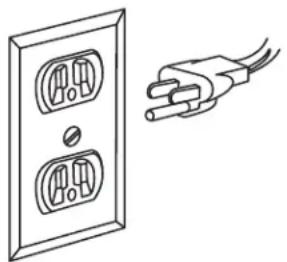
Plug power cord into a 110-120V properly grounded type outlet protected by a 15-amp dual element time delay fuse or circuit breaker.
Not all outlets are properly grounded. If you are not sure that your outlet, as pictured on this page, is properly grounded; have it checked by a qualified electrician.

DANGER
To avoid electric shock, do not touch the metal prongs on the plug when installing or plug to or from the outlet.

DANGER
Failure to properly ground this power tool can cause electrocution or serious shock, particu-
larly when used near metal plumbing or other metal objects. If shocked, your reaction could cause your hands to hit the tool.

DANGER
If power cord is worn, cut or damaged in any way, have it replaced immediately to avoid
shock or fire hazard.
natural_image
Line drawing of a wall socket connected to a power plug (no text or symbols)Figure 1. Grounded Wall Outlet
Your unit is for use on 120 volts; it has a plug that looks like the one in Figure 1.
This power tool is equipped with a 3-conductor cord and this plug requires a mating 3-conductor grounded type outlet as shown. It must be grounded in accordance with all local codes and ordinances.
If the outlet you are planning to use for this power tool is of the two-prong type, DO NOT REMOVE OR ALTER THE GROUNDING PRONG IN ANY MANNER. Have a qualified electrician replace the TWO-prong outlet with a properly grounded THREE-prong outlet.
Improper connection of the equipment-grounding conductor can result in a risk of electric shock. If repair or replacement of the electric cord or plug is necessary, do not connect the equipment-grounding conductor to a live terminal.
Check with a qualified electrician or service personnel if the grounding instructions are not completely understood, or if in doubt as to whether the tool is properly grounded.
Always use proper extension cord. The use of any extension cord will cause some loss of power. To keep this to a minimum and to prevent overheating and motor burn-out, use the table below to determine the minimum wire size (A.W.G.) extension cord. Use only 3-wire extension cords which have 3-prong grounding type plugs and 3-pole receptacles which accept the tool's plug. Make sure your extension cord is in good condition.
Extension Cord Length
Wire Size A.W.G.
0-25 feet 18
26-50 feet 16
51-100 feet 16
SAVE THESE INSTRUCTIONS
Unpacking & Checking Contents

WARNING
To avoid injury from unexpected starting or electrical shock, always remove plug from en tool is not in use.
Model 1800 Scroll Station is shipped complete in one carton.
Separate all "loose parts" from packing materials and check each item with the "Packing List" to make sure all items are accounted for before discarding any packing material.

WARNING
If any parts are missing, do not attempt to operate Scroll Station, plug in the power cord which on until the missing parts are obtained and correctly.
Packing List
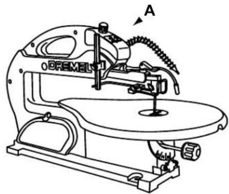
Item Description Qty.
A 18" Scroll Station ....1
B Owner's Manual 1
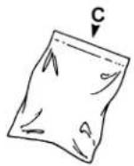
C Parts Bag (containing) 1
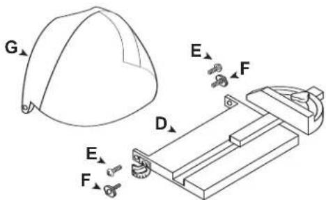
D Side Table with Side Miter ....1
E Flat Head Screws....2
F Wing Knobs 2
G. Flip-up Guard ....1
Allen Wrench (2 mm, 2.5 mm & 4 mm) .....1
Drive Screw for Flex Shaft Attachment ....1
Adaptor for future additions ....1
Spacer 2
O Ring 2
Drive Nut ....1
Blades 12
To remove protective coating from the table surface, moisten a soft cloth with kerosene or WD-40 and wipe off coating. Do not use acetone, gasoline or lacquer thinner for this purpose.
After removing protective coating, If you wish, you may apply a coat of paste wax to the table to allow the workpiece to slide easily across the table surface and deter rust. Wipe the table thoroughly with a clean dry cloth.
NOTE: Hardware to mount this Scroll Station to a bench or leg set is NOT supplied. See ASSEMBLY-MOUNTING THE SCROLL STATION, Page 8, for recommended hardware size.
IMPORTANT! If you require any assistance with these instructions, please contact the Dremel Service Department at: 1-809-427-3625
1-800-437-3635
Tools Needed
Phillips Screwdriver (not included)

Combination Square (not included)
natural_image
Line drawing of a Bremel sewing machine with no visible text or symbols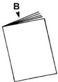
natural_image
Simple line drawing of a blank rectangular sheet with a downward arrow labeled 'B' pointing to the top-left corner (no text or symbols on the sheet itself)
natural_image
Simple line drawing of a folded paper or sheet with a downward arrow labeled 'C' pointing to the top edge (no text or symbols beyond the label)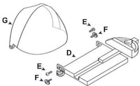
Figure 2. Packing List Parts
Combination Square Must be True
- Use the straight edge of a 3/4" thick board (this edge must be perfectly straight).
- Draw a line on the board along this edge.
- There should be no gap or overlap when the square is flipped over in dotted position.
Getting to Know Your Scroll Station
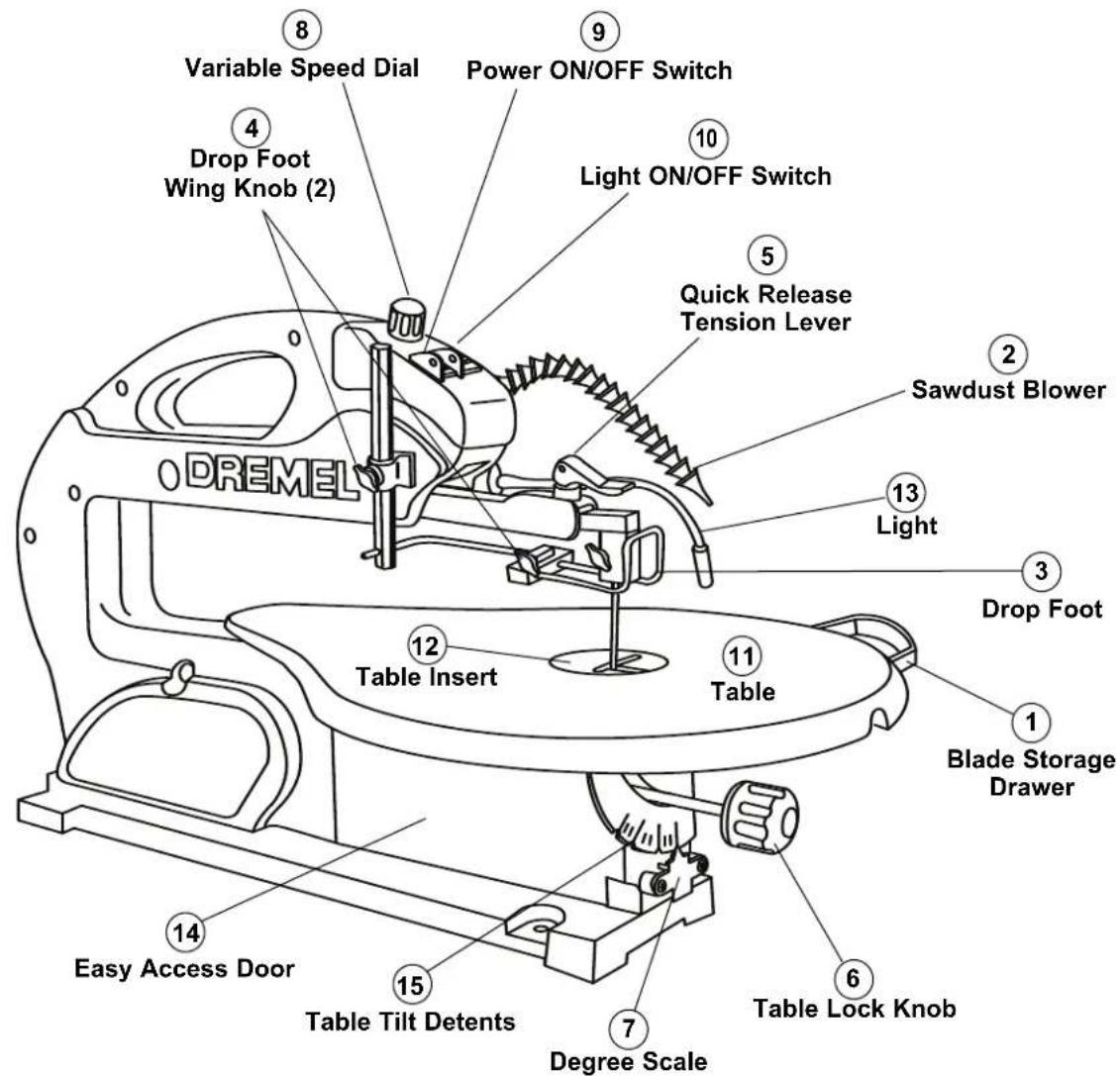
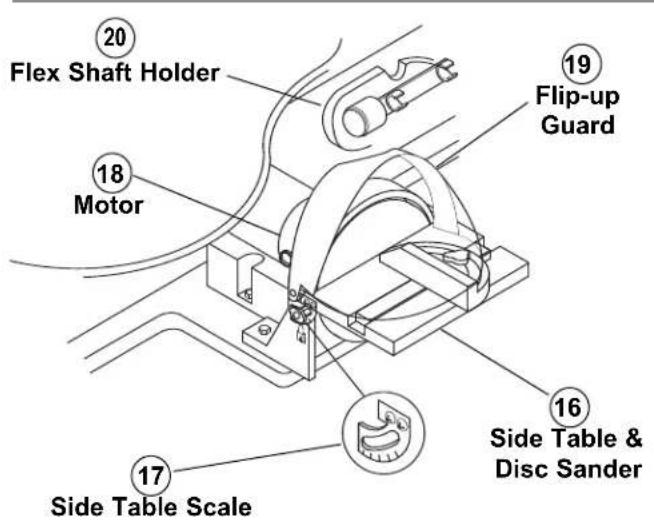
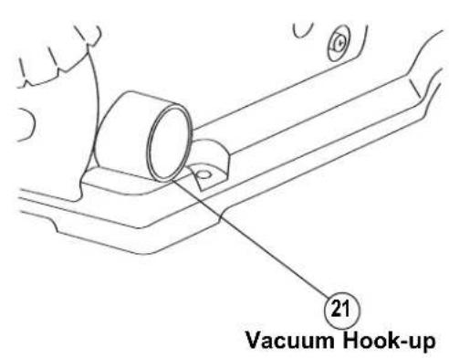
Figure 3. Scroll Station Components
Getting to Know Your Scroll Station
This versatile Scroll Station is great for making toys, puzzles, games, fretwork, and jewelry. Because of its cutting capacity, it is a handy do-it-yourself tool. It cuts wood up to 1fl" thick as well as plastics and non-ferrous metals.
1. BLADE STORAGE DRAWER
Your Scroll Station is equipped with a blade storage area located under the right side of the saw table (when facing table). The blade storage area conveniently stores both Pin-and Plain-end blades.
2. SAWDUST BLOWER
Keeps workpiece clean for better visibility. For best results, always direct air flow from blower tube at blade and workpiece. To adjust, simply bend to desired position.
3. DROP FOOT
The drop foot should always be lowered until it just rests on top of the workpiece to prevent workpiece from lifting, but not so much that the workpiece drags.
4. DROP FOOT WING KNOBS
Allows you to adjust the height and rotation of the drop foot and lock it into the desired position.
Allows you to quickly loosen, or tighten the blade to its proper tension with lever action.
6. TABLE LOCK KNOB
Allows you to tilt the table and lock it at desired angle up to 45^ to the left or 5^ to the right.
7. DEGREE SCALE
Shows the degree the table is tilted.
8. VARIABLE SPEED DIAL
Your Scroll Station is equipped with a variable speed dial for greater versatility.
9. POWER ON/OFF SWITCH
Has holes provided by the switch for a lock (not included). THIS FEATURE IS INTENDED TO PREVENT UNAUTHOURIZED AND POSSIBLY HAZARDOUS USE BY CHILDREN AND OTHERS. To turn saw on, push power switch to the ON (I) position; to turn saw off, push power switch to the OFF (O) position.
10. LIGHT SWITCH
To turn light on, push light switch to the ON (I) position; to turn light off, push light switch to the OFF (O) position.
11. TABLE
Provide working surface to support workpiece.
12. TABLE INSERT
Insert may be removed for ease of changing blades. Insert should always be in place and flush with table during cutting operation.
13. LIGHT
Illuminates the workpiece.
14. EASY ACCESS DOOR
Allows easy access to lower blade holder when changing blades.
15. TABLE TILT DETENTS
Automatically stops the table to the left at 0^ , 15^ , 30^ , and 45^ increments, and to the right up to 5^ .
16. SIDE TABLE & DISC SANDER
Allows multiple positions for sanding work piece.
17. SIDE TABLE TILT SCALE
Displays adjustments at 0^ , 15^ , 30^ , and 45^ increments.
18. MOTOR
Provides power to the disc sander and optional flex shaft tool.
19. FLIP-UP GUARD
Protects disc sander when saw is in operation.
20. FLEX SHAFT HOLDER
Protects flex shaft (if attached) when saw is in operation. Flex shaft should be disconnected before sawing is performed.
21. VACUUM HOOK-UP
Your Scroll Station is equipped with a vacuum hook-up. This feature will allow you to attach any 1-1/4" vacuum hose into the hole provided for convenient sawdust removal.
Glossary of Terms
KERF The slot cut by the blade.
LEADING EDGE
The edge of the workpiece which is pushed into the blade first.
SAWBLADE PATH
The area of the workpiece directly in line with and moving toward the sawblade edge.
BLADE TOOTH SET
The distance that the edge of the sawblade tooth is bent (onset) outward from the side of the blade.
TRAILING EDGE
The workpiece edge last cut by the sawblade.
WORKPIECE
The item on which the cutting operation is being performed.
Assembly
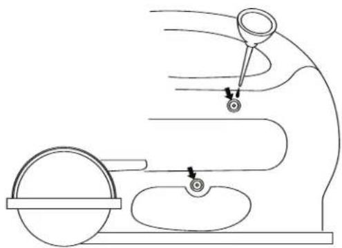
Installing the Disc Table & Guard
Refer to Figure 4.
Assemble the side table and guard, using two wing knobs, large spacers, flat head screws, and o-rings. Put spacers on wing knobs, then insert through sliding scales on sides of table and screw into bottom holes in base. Next, insert flat head screws through clear plastic guard, then though o-rings and tighten into top holes on table and base. Adjust table to desired angle and tighten wing knobs.
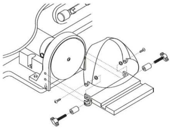
Installing the Flex Shaft (Optional Accessory - Model 225)
The optional flex shaft is used mainly for drilling pilot holes when making interior scroll cuts (see OPERATION) or for sanding. Also refer to the manual supplied with the Flex Shaft.
Refer to Figure 5.
- Remove the two Phillips head mounting screws and wing knobs securing the side table to the guard.
- Remove the Phillips head screw securing the disc to the motor and remove the disc.
- Insert the drive screw (supplied with the Scroll Station) into the end of the motor shaft and tighten securely.
- Insert square cable through the square hole in the drive screw and fully into the motor shaft.
- Secure the flex shaft to the motor shaft and tighten securely.
- Flex shaft should be disconnected from the motor shaft before sawing is performed.

Flex shaft must be stored in holder when attached and not in use.

Do not engage shaft lock on handpiece while motor is running.
natural_image
Technical line drawing of a mechanical assembly with rollers and mounting base (no text or symbols)Figure 4. Installing the Side Table

Figure 5. Installing the Flex Shaft (optional accessory)
Assembly
Mounting the Scroll Station to a Bench
The Scroll Station should be fastened securely to a firm supporting surface such as a stand or workbench, using the three mounting holes.
NOTE: When mounting this saw to a workbench, a solid bench is preferable to a plywood bench where noise and vibration will be more noticeable.
We recommend to reduce noise and vibration, that a soft foam pad be placed between your Scroll Station and workbench (not included).
Quantity Description
1 Soft foam pad, such as carpet padding, 24"x12"x1/2"
When mounting the Scroll Station to a workbench, holes should be drilled through the foam pad or carpet and mounting surface of the workbench using the dimensions illustrated in Figure 6.
Each of the three mounting holes should be bolted securely using no less than 1/4" hex bolts, flat washers, lockwashers, and nuts (not included). We recommend:
Quantity Description
4 Hex Head Bolts, 1/4"-20 x 1/4"-20 x Length Required 4 Flat Washers, 9/32" I.D. 4 Lockwasher, 9/32" I.D. 8 Hex Nuts, 1/4"-20 (Hardware not included)
Refer to Figures 6 and 7.
-
Locate and mark where the Scroll Station is to be mounted.
-
Drill the three (3) 5/16" holes through the workbench.
-
Place the Scroll Station on the workbench aligning holes in the base with the holes drilled in the workbench. Insert all three (3) bolts and secure using washers, lockwashers and nuts.
NOTE: Do NOT overtighten mounting bolts. If using recommended foam pad, leave some cushion in the foam pad for absorbing noise and vibration.
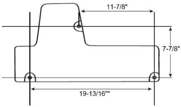
Figure 6. Bench Mounting Template
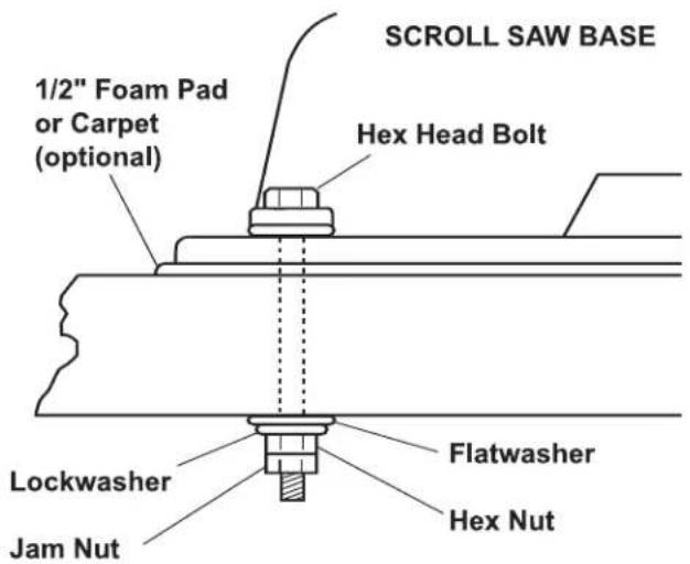
Figure 7. Table Mounting Hardware (not included)
Assembly
Mounting the Scroll Station to Plywood
An alternative method of securing your Scroll Station is to fasten the Scroll Station base to a mounting board 18" x 24". Any good grade of plywood with a 3/4" minimum thickness is recommended. Follow the instructions for MOUNTING THE SCROLL STATION TO A BENCH, substituting the 18" x 24" board for the workbench and using 1/4"-20 flat head screws for the hex head bolts (Figure 7). Screws must be mounted from underneath the plywood with washers and nuts on top.
NOTE: For proper stability, holes must be countersunk so screw heads are flush with the bottom surface of the supporting board.
Securely clamp board to workbench using two or more "C" clamps.
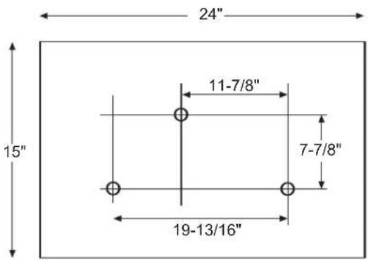
Figure 8. Plywood Mounting Template
Operation
Basic Scroll Station Operations
Follow these instructions for operating your Scroll Station to get the best results and to minimize the likelihood of personal injury.

WARNING
Always observe the safety precautions here and on pages 2 - 6.
Protection: Eyes, Hands, Face, Ears and Body

WARNING
To avoid being pulled into the saw blade –
DO NOT WEAR:
- Loose Fitting Gloves
- Necktie
- Loose Clothing
- Jewelry
DO:
-
Tie Back Long Hair
• Roll Long Sleeves Above Elbows -
The saw does not cut wood by itself. You allow the saw to cut wood by guiding the wood into the blade as it moves.
- The blade teeth cut ONLY on the down stroke.
- The drop foot should always be lowered until it just rests on top of the workpiece.
- You must feed the wood into the blade slowly because the teeth of the blade are very small and they can only remove wood when they are on the down stroke. The blade will flex backwards when applying feed pressure. Too much feed pressure will cause blade breakage. Let the blade do the work.
- There is a learning curve for each person who wants to use this saw. During that period of time it is expected that some blades will break until you learn how to use the saw and receive the greatest benefit from the blades.
- Best results are achieved when cutting wood less than 1" thick.
- When cutting wood thicker than 1", the user must feed the wood very slowly into the blade, increase blade tension and take extra care not to bend or twist the blade while cutting in order to maximize blade life.
- Teeth on Scroll Station blades wear out and blades must be replaced frequently for best cutting results. Scroll Station blades generally stay sharp for 1/2 hour to 2 hours of cutting.
- To get accurate cuts, be prepared to compensate for the blade's tendency to follow the wood grain as you are cutting.
When choosing a blade to use with your Scroll Station consider the following carefully:
- Choose a blade that allows at least three (3) teeth to be in contact with the workpiece at all times.
-
Very fine, narrow blades should be used to scroll cut in thin wood (1/4" thick or less).
-
To cut thicker wood, use wider blades with fewer teeth per inch.
- Most blade packages state the size or thickness of wood which that blade is intended to cut, and the radius (size of curve) which can be cut with that blade.
- Wider blades can't cut curves as tight or small as thinner blades.
- This saw uses 5" long, Pin- or Plain-End type blades only (See RECOMMENDED ACCESSORIES on page 21).
- Blades wear faster when (1) cutting plywood, which is very abrasive, (2) when sawing wood which is thicker than the 3/4" blade stroke, (3) when sawing hardwood or (4) when side pressure is placed on the blade.
Blades
Your new Scroll Station accepts 5" Pin-End blades or 5" Plain-End blades (See RECOMMENDED ACCESSORIES on page 21).
The blades can be used in either 0^ (forward facing) or 90^ (to the left) position.
- Remove hex bolt from upper and lower blade holders.
- Remove blade holders and rotate 90^ so the blade slot faces the left side of the saw.
- Re-install hex bolts and tighten securely.

WARNING
To prevent personal injury always disconnect the plug from power source before changing
blades or making adjustments.
Removing and Installing Pin-End Blades
- Release blade tension by lifting up the Quick Release Tension Lever and turning counterclockwise (Figure 11).
- Open easy access door and loosen the blade clamping knobs on the upper and lower blade holders. Remove blade from the upper and lower blade holders by pulling forward on blade and then lifting the blade through the access hole in the table. Slight downward pressure against the upper holder may be helpful when removing blade from upper holder.
NOTE: Table insert may be removed for better access. Table insert must be replaced before operating the saw.
- Look at the blade holders closely and notice the blade slots and pin recesses in the blade holders.
NOTE: In order to cut, and avoid uncontrollable lifting of the workpiece, the teeth of the blade used on the Scroll Station should always point downward as shown in (Figure 11) when installed.
Operation
-
Install the blade by inserting one end of the blade through the access hole in the table and hook the blade pin in the pin recess in the lower blade holder. Slide the top blade pin into the pin recess of the upper blade holder. You may need to press down lightly on the upper blade holder to install the blade.
-
Check to see that the pins are properly located in the blade holders.
-
To properly secure the blade securely tighten the wing knob on the upper and lower holders.
-
Tension blade (see BLADE TENSION below).
Removing and Installing Plain-End Blades
-
Release blade tension by lifting up the Quick Release Tension Lever (Figure 11) and turn counterclockwise.
-
Open easy access door and loosen the blade wing knob on the upper and lower blade holders (Figure 9). Remove blade from the upper and lower blade holders by pulling forward on blade and then lifting the blade through the access hole in the table. Slight downward pressure may be necessary on the upper arm.
NOTE: Table insert may be removed for better access. Table insert must be replaced before operating the saw.
-
Install the blade by inserting one end of the blade through the access hole in the table and centering the blade in the blade slot in the upper and lower blade holders (Figure 10).
-
To properly secure the blade securely tighten the wing knob on the upper and lower holders.
-
Tension blade (see BLADE TENSION below).
NOTE: In order to cut, and avoid uncontrollable lifting of the workpiece, the teeth of the blade used on the Scroll Station should always point downward as shown in (Figure 9) when installed.
Blade Tension
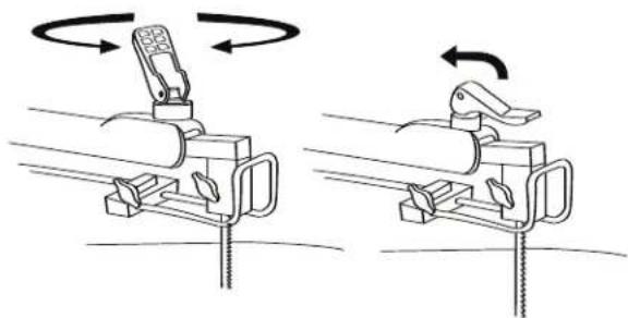
To tension blade, move Quick Release Tension Lever to "down" position. As the lever is lowered, tension will be applied to the blade (Figure 11).
ATTENTION: Moving the lever downward should require moderate, steady pressure only. If heavy pressure is needed, the blade is too tight. Loosen tension by rotating the Quick Release Tension Lever counterclockwise 1-2 turns, then reset the tension lever to the "down" position. If the tension lever is in the "down" position and the blade is too loose, you can increase tension by leaving the tension lever "down" and rotating it clockwise just until you feel the slack in the blade
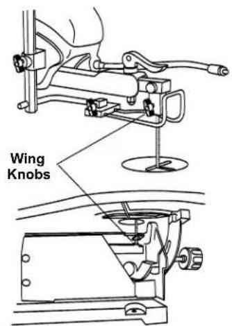
Figure 9. Changing Blades
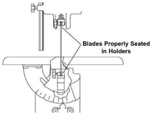
Figure 10. Installing Blades
natural_image
Diagram showing two mechanical clamping setups with rotating components and directional arrows indicating rotation (no text or symbols)Figure 11. Quick Release Tension Lever
removed. Then turn the tension lever ONE full turn clockwise. This amount of blade pressure should do well for most cutting operations and blades.
When the blade tension has been properly adjusted, you should be able to lift up the Quick Release Tension Lever, remove and install the blade, lower the lever and return the original blade tension. The life of the tension lever will be extended if you back the tension off one-half turn before lifting the lever.
NOTE: It may be necessary to re-adjust the tension lever when using different types of blades.
Operation
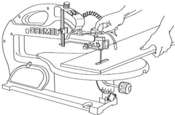
Making Interior Scroll Cuts
(Pin-End Blades & Plain-End Blades)

WARNING
TO AVOID ACCIDENTAL STARTING,
| ALWAYS TURN SWITCH TO OFF (O) AND
REMOVE PLUG FROM POWER SOURCE BEFORE REMOVING OR REPLACING THE BLADE.
A main benefit of this saw is the ability to perform intricate interior cuts quickly and easily. This is best accomplished using the Quick Release Tension Lever. Simply follow these steps (Figure 12):
- Drill appropriate sized pilot hole in work piece.
- Release Quick Release Tension Lever.
- Remove the blade from the upper blade holder as explained on page 14 or 15, REMOVING AND INSTALLING BLADES.
- Thread blade through pilot hole from underneath the workpiece. If needed, remove the table insert. This will allow the blade to angle forward for more clearance between the workpiece and the upper arm housing. Reinstall the blade in the upper blade holder. Replace table insert.
- Re-tension blade by pulling tension lever down.
- Lower drop foot until it just rests on top of the workpiece and you're ready to begin cutting.
- When finished making the interior scroll cuts simply remove the blade from the upper blade holder, as described on page 14 & 15, REMOVING AND INSTALLING BLADES, then remove the board from the table.
Adjusting the Table for Horizontal or Bevel Cutting
- Loosen the table lock knob, and the saw table can be tilted to the left and locked at any angle from 0° horizontal cutting position up to 45° for bevel cutting (Figure 15). Your tool also features table tilt detents which audibly click into place to the left every 15°. The table may be tilted to the right up to 5°.
- A degree scale is provided under the work table as a convenient reference for setting the approximate table angle for bevel cutting. When greater precision is required, make practice cuts and adjust the table as necessary for your requirements.
- Loosen the drop foot wing knob and lower by hand until it just rests above the workpiece surface, then securely tighten the drop foot wing knob. The drop foot should always rest just above the workpiece to help prevent the workpiece from lifting off the table.
natural_image
Line drawing of hands operating a Dremel sewing machine (no text or symbols present)Figure 12. Making Interior Scroll Cuts
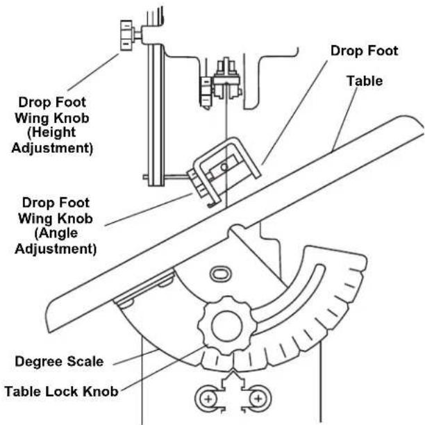
Figure 13. Adjusting Table for Horizontal or Bevel Cutting
- When cutting with the table angled, adjust drop foot so it's parallel to the table. To adjust, loosen the wing knob, turn drop foot to correct angle, tighten wing knob (Figure 13).
Always make sure the blade does not contact either side of the drop foot, table opening or insert.
NOTE: When cutting at extreme angles, the drop foot should be lifted off the workpiece, as it will impede cutting. Hold the workpiece against the table.
Operating Adjustments
Aligning the Degree Scale Pointer
The table is factory set to 0°. If further adjustments are necessary, please follow the instructions below:
- Loosen the table lock knob and move the table until it is 90° to the blade.
- Remove the blade, remove the drop foot assembly, then reinstall the blade (see REMOVING AND INSTALLING BLADES, page 14 or 15). Place a small square on the table next to the blade as shown in (Figure 14) to check if the table is 90° to the blade. If no adjustment is required, re-install the drop foot assembly.
If adjustment is necessary. Loosen, but don't remove the two screws holding the pointer. With the steel ball centered in the 0^ detent, slide the pointer left or right until the blade is parallel to the square. - Tighten the table lock knob, both screws, and reinstall the drop foot. Remember, the degree scale is a convenient guide but should not be relied upon for precision. Make practice cuts in scrap wood to determine if your angle setting is correct.
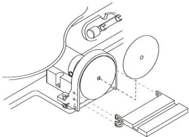
Removing and Installing Abrasive Discs
The disc furnished with the sander is self-adhesive type. Refer to Figure 15.
- Remove the disc table adjustment wing knobs and Phillips hd. screws, then remove the disc table.
- To remove the abrasive disc, work the edge of disc back then peel it away from the backing plate.
- Rotate the disc and continue peeling until it is removed.
- Remove the protective backing from the new disc. Carefully center disc on backing plate and apply pressure to disc.
- Install disc table using Phillips hd. screws and lock knobs.
Power ON/OFF Switch
Turn the power on or off using the Power ON (I) / OFF (O) switch (Figure 16).
Your saw features an overload switch that protects the motor from overheating and damage. If the switch is tripped, the motor will automatically stop. When this occurs, turn the ON/OFF switch to the OFF (O) position. The tool will automatically reset. Turn the power switch to the ON (I) position.
Adjusting the Lamp
Turn the lamp switch to ON (I). Position the lamp as needed to illuminate the workpiece (Figure 16).
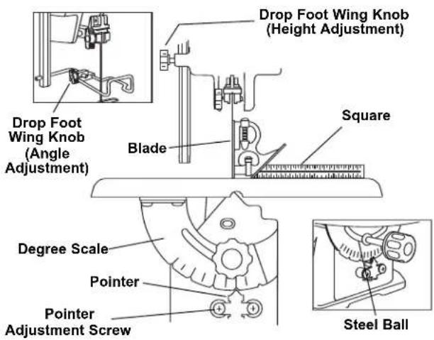
Figure 14. Aligning the Degree Scale Pointer
natural_image
Technical line drawing of a mechanical assembly with pulley, gears, and mounting base (no text or symbols)Figure 15. Removing and Installing Abrasive Discs

Figure 16. Adjusting the Lamp or Blower
Operating Adjustments
Adjusting the Blower
Position the blower as needed to blow-off sawdust from the workpiece (Figure 16).
Variable Speed Control
Turn the control to vary the speed of the saw, disc sander and other optional attachments (Figure 16).
Adjusting Side Table
- Loosen the side table lock knobs and move the side table to the desired angle. A scale is located under the left side lock knob (Figure 17).
- Tighten the wing knobs.
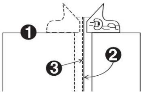
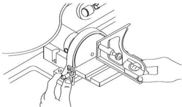
Squaring Side Table
For most projects, the table should be square with the sanding disc. Check using a combination square (Figure 18).
- Place a square on the table with the other end against the sanding disc. Check that the table is 90° to the disc.
- If the table is not 90^ to the disc, loosen the adjustment wing knobs and move the table to the desired position. Tighten adjustment knobs and check again for square-ness.
NOTE: Any desired angle can be checked the same way using a protractor instead of a square.

WARNING
Sanding is done only on the forward half of the disc as shown in Figure 19, with the supported by the table. If the back half of the dust and grit will be thrown up in your face, kpiece can be pulled out of your hands painfully abraded fingers.
The miter gauge (Figure 19) is used for making most angle cuts, such as the corners of a frame. The angle setting on the table should be used only for rough work. To make perfect joints, such as required for picture framing, a protractor should be used to make settings. Adjustments are made by loosening wing knobs, moving gauge to desired angle, then tightening wing knobs.
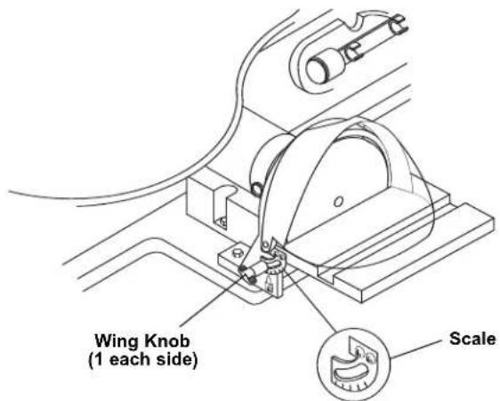
Figure 17. Adjusting the Side Table Angle
natural_image
Technical line drawing of hands operating a mechanical clamp or bracket assembly (no text or symbols present)Figure 18. Checking Side Table Squareness
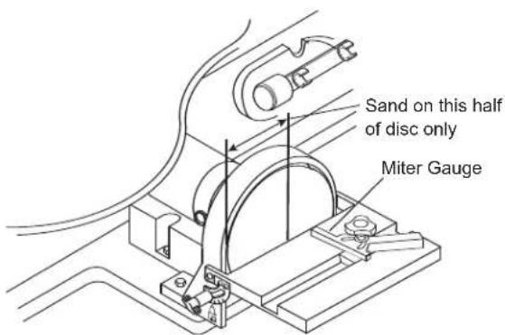
Figure 19. Disc Sanding Surface
Maintaining Your Scroll Station
General

For your own safety, turn power switch to OFF and remove plug from the power source out-
let before maintaining or lubricating your Scroll Station.
Frequently blow out any dust that may accumulate inside the motor.
An occasional coat of paste wax on the work table will allow materials being cut to glide smoothly across the work surface and deters rust.

Certain cleaning agents and solvents damage plastic parts. Including: gasoline, carbon tetra-
chloride, chlorinated cleaning solvents, ammonia and household detergents that contain ammonia. Avoiding use of these and other types of cleaning agents minimizes the probability of damage.

To avoid shock or fire hazard, if the power cord is worn or cut, or damaged in any way,
have it replaced immediately.

All repairs, electrical or mechanical, should be attempted only by trained repairmen. Contact
the nearest Dremel Factory Service Center. Use only Dremel replacement parts, any others may create a hazard.
Carbon Brushes
The brushes and commutator in your tool have been engineered for many hours of dependable service. To maintain peak efficiency of the motor, we recommend the brushes be examined every two to six months. Only genuine Dremel replacement brushes specially designed for your tool should be used.
The brushes should be inspected frequently when tools are used continuously. If your tool runs sporadically, loses power, makes unusual noises or runs at a reduced speed, check the brushes. To continue using the tool in this condition will permanently damage your tool.
With the cord unplugged, remove the brush caps one at a time with a small screwdriver by rotating cap counter-clockwise and check each brush (Figure 20).
If the brush is less than 1/8" long and the end surface of the brush that contacts the commutator is rough and/or pitted, replace the brush. Check both brushes. Usually the brushes will not wear out simultaneously. If one brush is worn out, replace both brushes. Make sure the brushes are installed as illustrated. The curved surface of the brush must match the curvature of the commutator.
After replacing brushes the tool should be run at no-load; place it on a clean surface and run it freely for 5 minutes before loading (or using) the tool. This will allow the brushes to "seat" properly and will give you more hours of life from
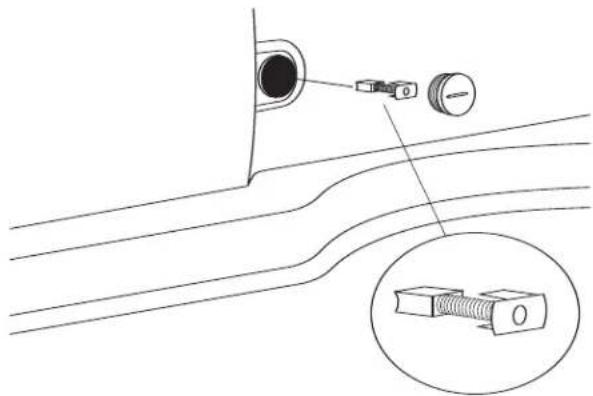
Figure 20. Checking Motor Carbon Brushes
natural_image
Diagram of a scientific apparatus with a curved surface, a sphere, and a droplet inserted into a ring (no text or labels)Figure 21. Lubrication
each set of brushes. This will also extend the total life of your tool since the commutator surface will wear longer.
Lubrication
ARM BEARINGS
Lubricate the arm bearings with oil after 10 hours of use. Re-oil after every 50 hours of use or whenever there is a squeak coming from the bearings.
TO LUBRICATE
- Remove rubber plug to expose bronze bearing.
- Squirt a generous amount of SAE 20 oil around the shaft end and bronze bearing.
- Replace rubber plug.
- Let the oil soak in overnight in this condition.
Troubleshooting

WARNING
Turn power switch to "OFF" (O) and always remove plug from the wall outlet before troubleshooting.
| TROUBLE | PROBLEM | REMEDY |
| Breaking blades. | Wrong tension.Over working blade.Wrong blade application.Twisting blade in wood.Incorrect teeth per inch. | Adjust blade tension, see REMOVING AND INSTALLING BLADES, Pages 14 & 15.(Pin End) or (Plain End).Reduce feed rate, see BASIC Scroll Station OPERA-TION, Page 14.Use narrow blades for cutting thin wood, wide blades for thicker wood.Avoid side pressure on blade - avoid over-tensioning pin-end blade.Blade should have minimum 3 teeth in contact with workpiece. |
| Jammed disc sander | Material jammed in disc. | Turn off and unplug saw.Remove material. |
| Motor will not run. | Defective cord or plug.Defective motor.Defective wire connections.Brushes worn. | Replace defective parts before using saw again.& 3. Consult Dremel Service. Any attempt to repair this motor may create a HAZARD unless repair is done by a qualified service technician.Replace both brushes. |
| VibrationNOTE: There will always be some vibration present when the saw is running because of motor operation. | Improper mounting of saw.Unsuitable mounting surface.Loose table or table resting against motor. | See MOUNTING YOUR Scroll Station, Pages 12 & 13.The heavier your work bench is, the less vibration will occur. A plywood workbench will not be as good a work surface as the same size solid lumber. Use common sense in choosing a mounting surface.Tighten table wing knob. |
Recommended Accessories
Use only Dremel accessories. Follow instructions that accompany accessories. Use of improper accessories may cause hazards.
LEG SET Magnifier
Cat. No.
Cat. No.
2615018500
2615018505
Dremel offers both Pin- and Plain-End 5 inch blades.
PIN-END SAW BLADES
Pin-End blades permit relatively tight radius cutting in hard and soft wood.
Cat. No. Suggested Usage Width Thick TPI Speed
16412 For cutting wood 3/8" to 2" thick .110" x .018" x 10 Any
16411 For cutting wood 3/16" to 1" thick .110" x .018" x 15 Any
16413 For cutting wood thinner than 1/4" thick .070" x .010" x 18.5 Any
PLAIN-END
The Pin-End blades, while somewhat easier to put in and take out of the machine, do not always produce the same controlled cutting action provided with the Plain-End blade. These narrow Plain-End blades allow the user to cut more detailed, intricate patterns and smaller inside cuts.
Cat.No. Suggested Usage Width Thick TPI Speed
16453 For cutting hard and soft woods 1/4" to 2" thick .062" x .020" x 9.5 High
16446 For close radius cutting in materials 1/8" or thicker
.038" x .016" x 12.5
High
16440 .022" x .010" x 28
High
SPIRAL
Saws in all directions without turning the workpiece.
Cat. No. Suggested Usage
Kerf
TPI
Speed
16463 For wood, plastic and abrasive materials
.034" - .036" x 41
METAL PIERCING
For cutting precious and non-ferrous metals; these must be used at very slow speeds.
They perform well on machines that have variable speed capability and should be lubricated with beeswax, or a light machine oil.
Cat. No. Suggested Usage
Kerf
TPI
Speed
16483 Metals and other hardwood materials.
.033" x .016" x 36
Low
REVERSE TOOTH
Provides a smooth, splinter free finish. Eliminates the need for excessive finish sanding, and leaves a clean sharp edge on both the top and bottom of your workpiece.
Cat. No. Suggested Usage
Kerf
TPI
Speed
16431 For cutting hard or soft woods up to 1/8" thick.
.029" x .012" x 20
Any
16432 For cutting hard or soft woods 1/8" or thicker
.038" x .016" x 12.5
Any
Dremel Limited Warranty
Your Dremel product is warranted against defective material or workmanship for a period of two years from date of purchase. In the event of a failure of a product to conform to this written warranty, please take the following action:
- DO NOT return your product to the place of purchase.
- Carefully package the product by itself, with no other items, and return it, freight prepaid, along with:
A. A copy of your dated proof of purchase (please keep a copy for yourself).
B. A written statement about the nature of the problem.
C. Your name, address and phone number to:
UNITED STATES
Dremel Service Center
Dremel Service Center
4915 21st Street OR 4631 E. Sunny Dune
Racine, WI 53406 Palm Springs, CA 92264
CANADA OUTSIDE
Giles Tool Agency CONTINENTAL UNITED STATES
6520 Lawrence Av. East See your local distributor or write
Scarborough, Ont. to Dremel, 4915 21st Street
Canada M1C 4A7 Racine, WI 53406
We recommend that the package be insured against loss or in transit damage for which we cannot be responsible.
This warranty applies only to the original registered purchaser. DAMAGE TO THE PRODUCT RESULTING FROM TAMPERING, ACCIDENT, ABUSE, NEGLIGENCE, UNAUTHORIZED REPAIRS OR ALTERATIONS, UNAPPROVED ATTACHMENTS OR OTHER CAUSES UNRELATED TO PROBLEMS WITH MATERIAL OR WORKMANSHIP ARE NOT COVERED BY THIS WARRANTY.
No employee, agent, dealer or other person is authorized to give any warranties on behalf of Dremel. If Dremel inspection shows that the problem was caused by problems with material or workmanship within the limitations of the warranty, Dremel will repair or replace the product free of charge and return product prepaid. Repairs made necessary by normal wear or abuse, or repair for product outside the warranty period, if they can be made, will be charged at regular factory prices.
DREMEL MAKES NO OTHER WARRANTY OF ANY KIND WHATEVER, EXPRESSED OR IMPLIED, AND ALL IMPLIED WARRANTIES OF MERCHANTABILITY AND FITNESS FOR A PARTICULAR PURPOSE WHICH EXCEED THE ABOVE MENTIONED OBLIGATION ARE HEREBY DISCLAIMED BY DREMEL AND EXCLUDED FROM THIS LIMITED WARRANTY.
This warranty gives you specific legal rights and you may also have other rights which vary from state to state. The obligation of the warrantor is solely to repair or replace the product. The warrantor is not liable for any incidental or consequential damages due to any such alleged defect. Some states do not allow the exclusion or limitation of incidental or consequential damages, so the above limitations or exclusion may not apply to you.
For prices and warranty fulfillment in the continental United States, contact your local Dremel distributor.
DREMEL®
Mode d'emploi
natural_image
Line drawing of a Dremelo industrial machine with no visible text or symbols
Table des Matières
natural_image
Line drawing of a wall socket connected to a power plug (no text or symbols)natural_image
Technical line drawing of a mechanical device with labeled component A (no text or symbols beyond label)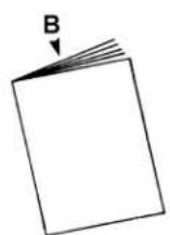
The edge of the workpiece which is pushed into the blade first.
TRAJECTOIRE DE LA LAME
natural_image
Technical line drawing of a mechanical assembly with rollers and mounting brackets (no text or symbols)natural_image
Diagram showing two mechanical lever mechanisms with rotating arrows indicating motion (no text or symbols)natural_image
Line drawing of a Dremel sewing machine with hands operating it (no text or symbols present)natural_image
Technical line drawing of a mechanical assembly with pulley, gears, and base plate (no text or symbols)natural_image
Technical line drawing of a mechanical assembly with hands operating a bracket (no text or symbols)natural_image
Diagram of a scientific apparatus with curved surfaces and labeled components (no text or symbols)Figure 21. Lubrification
Dépannage
! AVERTISSEMENT
Dremel Service Center
Dremel Service Center
4915 21st Street OU 4631 E. Sunny Dune
Racine, WI 53406 Palm Springs, CA 92264
CANADA EN DEHORS DES ÉTATS
Giles Tool Agency AMÉRICAINS CONTINENTAUX
Scarborough, Ont. to Dremel, 4915 21st Street
Canada M1C 4A7 Racine, WI 53406
natural_image
Line drawing of a Dremelo robotic machine with no visible text or symbols
natural_image
Line drawing of a wall socket connected to a power plug (no text or symbols)Figura 1. Tomacorriente de Pared Conectado a Tierra
Llave Allen (2 mm, 2.5 mm, y 4 mm)....1
natural_image
Line drawing of a manual cutting machine with labeled component A (no text or symbols on the machine itself)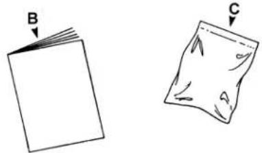
natural_image
Two hand-drawn diagrams showing a folded paper labeled B and a torn paper labeled C, with no text or symbols present.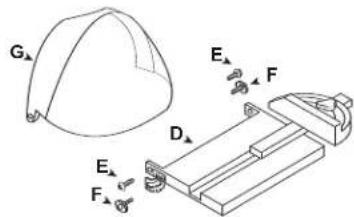
natural_image
Technical line drawing of a mechanical assembly with no visible text or symbolsnatural_image
Diagram showing two mechanical assembly steps with rotating arrows indicating motion (no text or symbols)Figura 11. Palanca Tensora de Suelta Rápida
natural_image
Line drawing of hands operating a Dremel sewing machine (no text or symbols present)natural_image
Technical line drawing of a mechanical device with rollers and mounting base (no text or symbols)natural_image
Technical line drawing of a mechanical assembly with hands operating a bracket (no text or symbols)natural_image
Diagram of a scientific apparatus with a curved surface, a sphere, and a dropper (no text or labels)Dremel Service Center Dremel Service Center
4915 21st Street O 4631 E. Sunny Dune
Racine, WI 53406 Palm Springs, CA 92264
CANADÁ FUERA DE
Giles Tool Agency LOS ESTADOS UNIDOS CONTINENTALES
Scarborough, Ont Dremel, 4915 21st Street
Canada M1C 4A7 Racine, WI 53406