
GA5040R01 - Garden shredder MAKITA - Free user manual and instructions
Find the device manual for free GA5040R01 MAKITA in PDF.
| Product type | Angle grinder (grinding, sanding, brushing, cutting) |
| Brand | Makita |
| Model | GA5040R01 |
| Max. wheel diameter (ordinary wheel) | 125 mm |
| Max. wheel thickness (ordinary wheel) | 7.2 mm |
| Max. wheel diameter (cutting) | 125 mm |
| Max. wheel thickness (cutting) | 3.2 mm |
| Max. diameter of circular wire brush | 125 mm |
| Shaft thread | M14 or 5/8" (depending on country) |
| Max. shaft length | 23 mm |
| No load speed | 9,000 min⁻¹ |
| Overall length | 325 mm |
| Net weight | 2.5 - 3.6 kg |
| Safety category | Double insulation (Class II) |
| Power supply | Single phase, voltage per nameplate, plug without ground |
| Main applications | Grinding, sanding, wire brushing, hole cutting, cutting metal or stone |
| Safety functions | Shaft lock, switch with lock-on, accidental restart prevention function, soft start, mechanical brake (depending on model) |
| Sound pressure level | 89 dB(A) |
| Sound power level | 97 dB(A) |
| Vibration emission (grinding with normal side handle) | 7.0 m/s² (K=1.5) |
| Vibration emission (disc sanding) | ≤2.5 m/s² (K=1.5) |
| Maintenance | Regular cleaning of ventilation openings, inspection and replacement of brushes by authorized center |
| Included accessories | Side handle, lock nut wrench, protective guard (depending on version) |
Frequently Asked Questions - GA5040R01 MAKITA
User questions about GA5040R01 MAKITA
0 question about this device. Answer the ones you know or ask your own.
Ask a new question about this device
Download the instructions for your Garden shredder in PDF format for free! Find your manual GA5040R01 - MAKITA and take your electronic device back in hand. On this page are published all the documents necessary for the use of your device. GA5040R01 by MAKITA.
USER MANUAL GA5040R01 MAKITA
| EN | Angle Grinding INSTRUCTION MANUAL 7 | |
| FR | Meuleuse d'Angle MANUEL D'INSTRUCTIONS 19 | |
| DE | Winkelschleifer BETRIEBSANLEITUNG 32 | |
| IT | Smerigliatrice angolare ISTRUZIONI PER L'USO 45 | |
| NL | Haakse slijpmachine GEBRUIKSAANWIJZING 58 | |
| ES | Esmeriladora Angular | MANUAL DE INSTRUCCIONES 71 |
| PT | Esmerilhadeira Angular MANUAL DE INSTRUÇões 84 | |
| DA | Vinkelsliber BRUGSANVISNING 97 | |
| EL | Γωνιακός λειαντήρας | ΕΓXEΙΡΙΑΟ OΔΗΓΙΩN 109 |
| TR | Taşlama Makinası | KULLANMA KILAVUZU 123 |
GA4540R
GA4541R
GA5040R
GA5041R
GA6040R
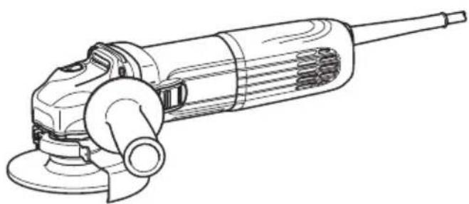
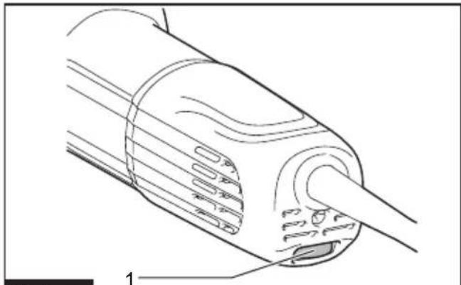
Fig.1
Fig.5
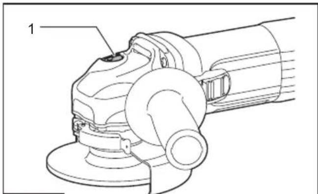
Fig.2
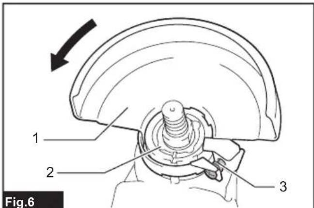
Fig.6
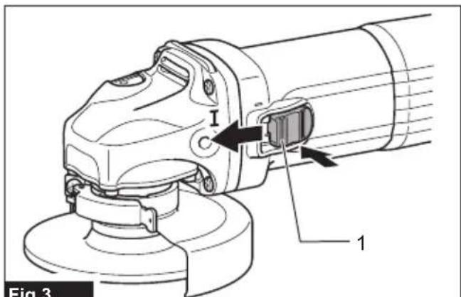
Fig.3
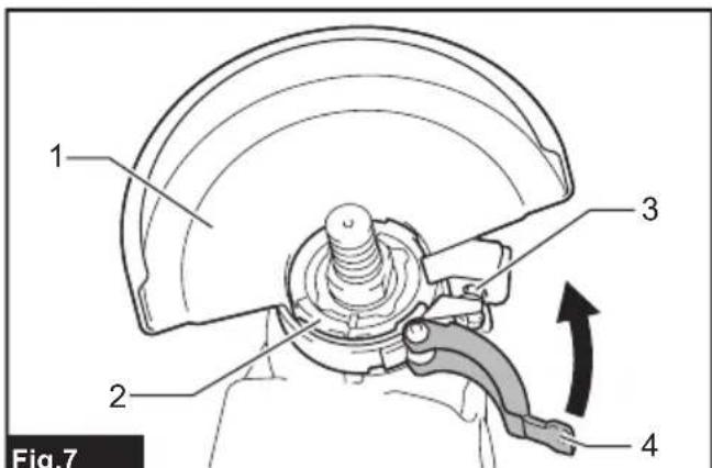
Fig.7


SPECIFICATIONS
| Model: GA4540R GA4541R GA5040R GA5041R GA6040R | ||||||
| Applicable grinding wheel Max. | wheel diameter 115 mm 125 mm 150 mm | |||||
| Max. wheel thickness 7.2 mm 6.4 mm | ||||||
| Applicable cut-off wheel Max. | wheel diameter 115 mm 125 mm 150 mm | |||||
| Max. wheel thickness 3.2 mm 3.0 mm | ||||||
| Applicable wire wheel brush Max. | wheel diameter 115 mm 125 mm | |||||
| Max. wheel thickness 20 mm | ||||||
| Spindle thread M14 or 5/8" (country specific) | ||||||
| Max. spindle length | 23 mm | |||||
| No load speed (n0) / Rated speed (n) | 11,000 min-1 | 9,000 min-1 | ||||
| Overall length | 303 mm | 325 mm | 303 mm | 325 mm | 303 mm | |
| Net weight | 2.4 - 3.6 kg | 2.7 - 3.8 kg | 2.5 - 3.6 kg | 2.7 - 3.8 kg | 2.5 - 3.0 kg | |
| Safety class | ☐/II | |||||
- Due to our continuing program of research and development, the specifications herein are subject to change without notice.
Specifications may differ from country to country.
The weight may differ depending on the attachment(s). The lightest and heaviest combinations, according to EPTA-Procedure 01/2014, are shown in the table.
Symbols
The followings show the symbols which may be used for the equipment. Be sure that you understand their meaning before use.

Read instruction manual.

Wear safety glasses.

Always operate with two hands.

Do not use the wheel guard for cut-off operations.

DOUBLE INSULATION

Only for EU countries
Due to the presence of hazardous components in the equipment, used electrical and electronic equipment may have a negative impact on the environment and human health.
Do not dispose of electrical and electronic appliances with household waste! In accordance with the European Directive on waste electrical and electronic equipment and its adaptation to national law, used electrical and electronic equipment should be collected separately and delivered to a separate collection point for municipal waste, operating in accordance with the environmental protection regulations.
This is indicated by the symbol of the crossed-out wheeled bin placed on the equipment.
Intended use
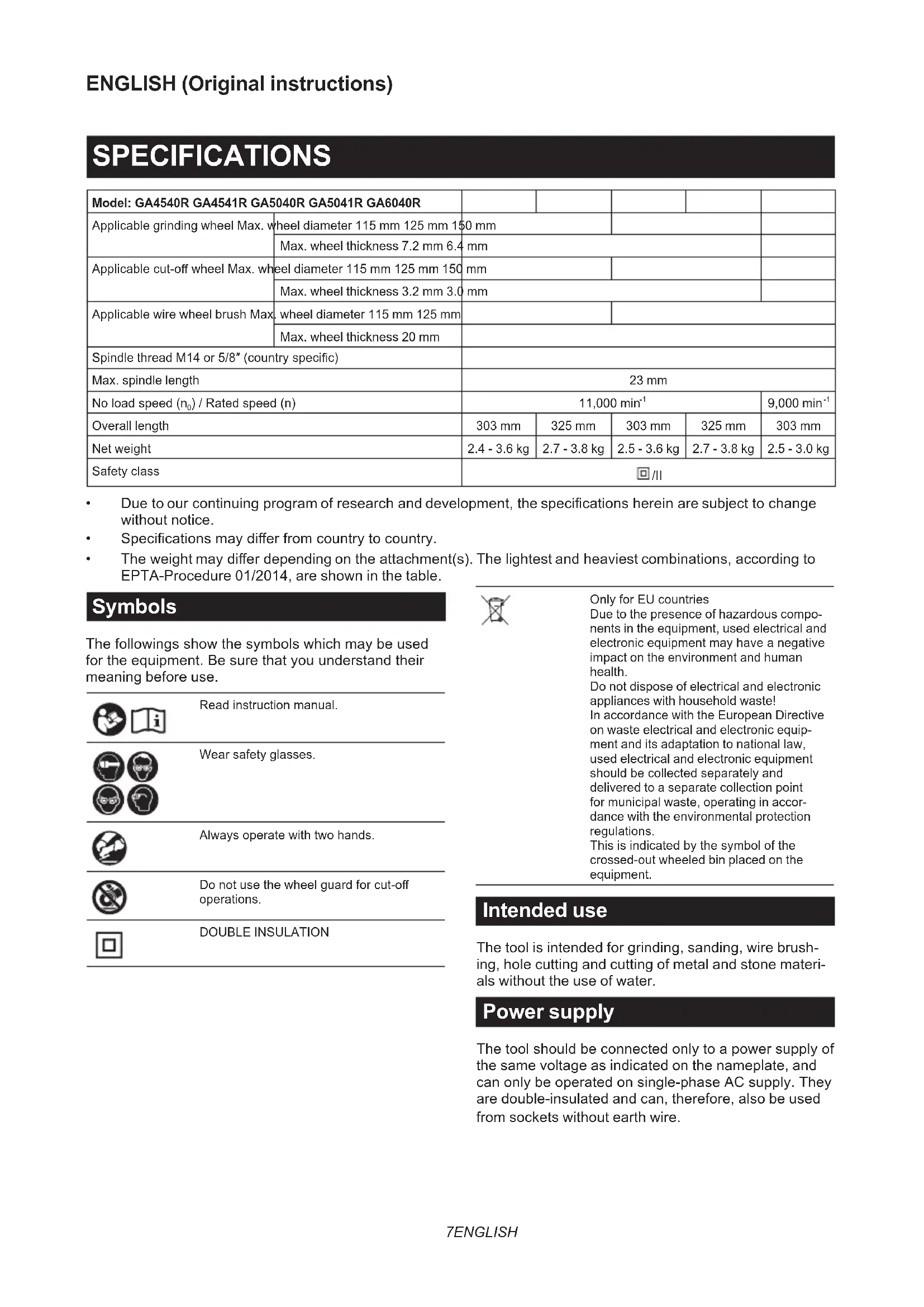
The tool is intended for grinding, sanding, wire brushing, hole cutting and cutting of metal and stone materials without the use of water.
Power supply
The tool should be connected only to a power supply of the same voltage as indicated on the nameplate, and can only be operated on single-phase AC supply. They are double-insulated and can, therefore, also be used from sockets without earth wire.
Noise
The typical A-weighted noise level determined according to EN62841-2-3:
| Model Sound pressure | level (LpA) : (dB(A)) | Sound power level (LwA) : (dB(A)) | Uncertainty (K) : (dB(A)) |
| GA4540R 89 97 3 | |||
| GA4541R 87 95 3 | |||
| GA5040R 89 97 3 | |||
| GA5041R 87 95 3 | |||
| GA6040R 90 98 3 |
NOTE: The declared noise emission value(s) has been measured in accordance with a standard test method and may be used for comparing one tool with another.
NOTE: The declared noise emission value(s) may also be used in a preliminary assessment of exposure.

WARNING: Wear ear protection.
WARNING: The noise emission during actual use of the power tool can differ from the declared value(s) depending on the ways in which the tool is used especially what kind of workpiece is processed.
WARNING: Be sure to identify safety measures to protect the operator that are based on an estimation of exposure in the actual conditions of use (taking account of all parts of the operating cycle such as the times when the tool is switched off and when it is running idle in addition to the trigger time).
WARNING: Grinding thin sheets of metal or other easily vibrating structures with a large surface can result in a total noise emission much higher (up to 15 dB) than the declared noise emission values.
Set heavy flexible damping mats or such to those workpieces to prevent them from emitting sound.
Take the increased noise emission into consideration for both the risk assessment of noise exposure and selecting adequate hearing protection.
Vibration
The vibration total value (tri-axial vector sum) determined according to EN62841-2-3:
Work mode: surface grinding with normal side grip
| Model | Vibration emission \( \left( {{a}_{n},{A}_{G}}\right) : \left( {\mathrm{m}/{\mathrm{s}}^{2}}\right) \) | Uncertainty (K) : \( \left( {\mathrm{m}/{\mathrm{s}}^{2}}\right) \) |
| GA4540R 6.5 1.5 | ||
| GA4541R 7.0 1.5 | ||
| GA5040R 7.0 1.5 | ||
| GA5041R 7.5 1.5 | ||
| GA6040R 7.0 1.5 |
Work mode: surface grinding with anti vibration side grip
| Model | Vibration emission \( \left( {{a}_{1},{A}_{G}}\right) : \left( {\mathrm{m}/{\mathrm{s}}^{2}}\right) \) | Uncertainty (K) : \( \left( {\mathrm{m}/{\mathrm{s}}^{2}}\right) \) |
| GA4540R 6.0 1.5 | ||
| GA4541R 6.0 1.5 | ||
| GA5040R 6.0 1.5 | ||
| GA5041R 6.0 1.5 | ||
| GA6040R 6.0 1.5 |
Work mode: disc sanding with normal side grip
| Model | Vibration emission \( \left( {{\mathrm{a}}_{\mathrm{h}},{}^{\prime }{}_{\mathrm{{DS}}}}\right) : \left( {\mathrm{m}/{\mathrm{s}}^{2}}\right) \) | Uncertainty (K) : \( \left( {\mathrm{m}/{\mathrm{s}}^{2}}\right) \) |
| GA4540R 2.5 m/s | \( {}^{2} \) or less 1.5 | |
| GA4541R 2.5 m/s | \( {}^{2} \) or less 1.5 | |
| GA5040R 2.5 m/s | \( {}^{2} \) or less 1.5 | |
| GA5041R 2.5 m/s | \( {}^{2} \) or less 1.5 | |
| GA6040R 2.5 m/s | \( {}^{2} \) or less 1.5 |
Work mode: disc sanding with anti vibration side grip
| Model | Vibration emission (ah, ds) : (m/s2) | Uncertainty (K) : (m/s2) |
| GA4540R 2.5 m/s | 2 or less 1.5 | |
| GA4541R 2.5 m/s | 2 or less 1.5 | |
| GA5040R 2.5 m/s | 2 or less 1.5 | |
| GA5041R 2.5 m/s | 2 or less 1.5 | |
| GA6040R 2.5 m/s | 2 or less 1.5 |
NOTE: The declared vibration total value(s) has been measured in accordance with a standard test method and may be used for comparing one tool with another.
NOTE: The declared vibration total value(s) may also be used in a preliminary assessment of exposure.
WARNING: The vibration emission during actual use of the power tool can differ from the declared value(s) depending on the ways in which the tool is used especially what kind of workpiece is processed.
WARNING: Be sure to identify safety measures to protect the operator that are based on an estimation of exposure in the actual conditions of use (taking account of all parts of the operating cycle such as the times when the tool is switched off and when it is running idle in addition to the trigger time).
WARNING: The declared vibration emission value is used for main applications of the power tool. However if the power tool is used for other applications, the vibration emission value may be different.
Declarations of Conformity
For European countries only
The Declarations of conformity are included in Annex A to this instruction manual.
SAFETYWARNINGS
General power tool safety warnings
WARNING Read all safety warnings, instructions, illustrations and specifications provided with this power tool. Failure to follow all instructions listed below may result in electric shock, fire and/or serious injury.
Save all warnings and instructions for future reference.
The term "power tool" in the warnings refers to your mains-operated (corded) power tool or battery-operated (cordless) power tool.
Grinder safety warnings
Safety warnings common for grinding, sanding, wire brushing, or cutting-off operations:
- This power tool is intended to function as a grinder, sander, wire brush, hole cutter or cut-off tool. Read all safety warnings, instructions, illustrations and specifications provided with this power tool. Failure to follow all instructions listed below may result in electric shock, fire and/or serious injury.
- Operations such as polishing are not to be performed with this power tool. Operations for which the power tool was not designed may create a hazard and cause personal injury.
-
Do not convert this power tool to operate in a way which is not specifically designed and specified by the tool manufacturer. Such a conversion may result in a loss of control and cause serious personal injury.
-
Do not use accessories which are not specifically designed and specified by the tool manufacturer. Just because the accessory can be attached to your power tool, it does not assure safe operation.
- The rated speed of the accessory must be at least equal to the maximum speed marked on the power tool. Accessories running faster than their rated speed can break and fly apart.
- The outside diameter and the thickness of your accessory must be within the capacity rating of your power tool. Incorrectly sized accessories cannot be adequately guarded or controlled.
- The dimensions of the accessory mounting must fit the dimensions of the mounting hardware of the power tool. Accessories that do not match the mounting hardware of the power tool will run out of balance, vibrate excessively and may cause loss of control.
- Do not use a damaged accessory. Before each use inspect the accessory such as abrasive wheels for chips and cracks, backing pad for cracks, tear or excess wear, wire brush for loose or cracked wires. If power tool or accessory is dropped, inspect for damage or install an undamaged accessory. After inspecting and installing an accessory, position yourself and bystanders away from the plane of the rotating accessory and run the power tool at maximum no-load speed for one minute. Damaged accessories will normally break apart during this test time.
-
Wear personal protective equipment. Depending on application, use face shield, safety goggles or safety glasses. As appropriate, wear dust mask, hearing protectors, gloves and workshop apron capable of stopping small abrasive or workpiece fragments. The eye protection must be capable of stopping flying debris generated by various applications. The dust mask or respirator must be capable of filtrating particles generated by the particular application. Prolonged exposure to high intensity noise may cause hearing loss.
-
Keep bystanders a safe distance away from work area. Anyone entering the work area must wear personal protective equipment. Fragments of workpiece or of a broken accessory may fly away and cause injury beyond immediate area of operation.
- Hold the power tool by insulated gripping surfaces only, when performing an operation where the cutting accessory may contact hidden wiring or its own cord. Cutting accessory contacting a "live" wire may make exposed metal parts of the power tool "live" and could give the operator an electric shock.
- Position the cord clear of the spinning accessory. If you lose control, the cord may be cut or snagged and your hand or arm may be pulled into the spinning accessory.
- Never lay the power tool down until the accessory has come to a complete stop. The spinning accessory may grab the surface and pull the power tool out of your control.
- Do not run the power tool while carrying it at your side. Accidental contact with the spinning accessory could snag your clothing, pulling the accessory into your body.
- Regularly clean the power tool's air vents. The motor's fan will draw the dust inside the housing and excessive accumulation of powdered metal may cause electrical hazards.
- Do not operate the power tool near flammable materials. Sparks could ignite these materials.
- Do not use accessories that require liquid coolants. Using water or other liquid coolants may result in electrocution or shock.
Kickback and related warnings:
Kickback is a sudden reaction to a pinched or snagged rotating wheel, backing pad, brush or any other accessory. Pinching or snagging causes rapid stalling of the rotating accessory which in turn causes the uncontrolled power tool to be forced in the direction opposite of the accessory's rotation at the point of the binding. For example, if an abrasive wheel is snagged or pinched by the workpiece, the edge of the wheel that is entering into the pinch point can dig into the surface of the material causing the wheel to climb out or kick out. The wheel may either jump toward or away from the operator, depending on direction of the wheel's movement at the point of pinching. Abrasive wheels may also break under these conditions.
Kickback is the result of power tool misuse and/or incorrect operating procedures or conditions and can be avoided by taking proper precautions as given below.
- Maintain a firm grip with both hands on the power tool and position your body and arms to allow you to resist kickback forces. Always use auxiliary handle, if provided, for maximum control over kickback or torque reaction during start-up. The operator can control torque reactions or kickback forces, if proper precautions are taken.
- Never place your hand near the rotating accessory. Accessory may kickback over your hand.
-
Do not position your body in the area where power tool will move if kickback occurs. Kickback will propel the tool in direction opposite to the wheel's movement at the point of snagging.
-
Use special care when working corners, sharp edges, etc. Avoid bouncing and snagging the accessory. Corners, sharp edges or bouncing have a tendency to snag the rotating accessory and cause loss of control or kickback.
- Do not attach a saw chain woodcarving blade, segmented diamond wheel with a peripheral gap greater than 10mm or toothed saw blade. Such blades create frequent kickback and loss of control.
Safety warnings specific for grinding and cutting-off operations:
- Use only wheel types that are specified for your power tool and the specific guard designed for the selected wheel. Wheels for which the power tool was not designed cannot be adequately guarded and are unsafe.
- The grinding surface of centre depressed wheels must be mounted below the plane of the guard lip. An improperly mounted wheel that projects through the plane of the guard lip cannot be adequately protected.
- The guard must be securely attached to the power tool and positioned for maximum safety, so the least amount of wheel is exposed towards the operator. The guard helps to protect the operator from broken wheel fragments, accidental contact with wheel and sparks that could ignite clothing.
- Wheels must be used only for specified applications. For example: do not grind with the side of cut-off wheel. Abrasive cut-off wheels are intended for peripheral grinding, side forces applied to these wheels may cause them to shatter.
- Always use undamaged wheel flanges that are of correct size and shape for your selected wheel. Proper wheel flanges support the wheel thus reducing the possibility of wheel breakage. Flanges for cut-off wheels may be different from grinding wheel flanges.
- Do not use worn down wheels from larger power tools. A wheel intended for larger power tool is not suitable for the higher speed of a smaller tool and may burst.
- When using dual purpose wheels always use the correct guard for the application being performed. Failure to use the correct guard may not provide the desired level of guarding, which could lead to serious injury.
Additional safety warnings specific for cutting-off operations:
- Do not "jam" the cut-off wheel or apply excessive pressure. Do not attempt to make an excessive depth of cut. Overstressing the wheel increases the loading and susceptibility to twisting or binding of the wheel in the cut and the possibility of kickback or wheel breakage.
-
Do not position your body in line with and behind the rotating wheel. When the wheel, at the point of operation, is moving away from your body, the possible kickback may propel the spinning wheel and the power tool directly at you.
-
When the wheel is binding or when interrupting a cut for any reason, switch off the power tool and hold it motionless until the wheel comes to a complete stop. Never attempt to remove the cut-off wheel from the cut while the wheel is in motion otherwise kickback may occur. Investigate and take corrective action to eliminate the cause of wheel binding.
- Do not restart the cutting operation in the workpiece. Let the wheel reach full speed and carefully re-enter the cut. The wheel may bind, walk up or kickback if the power tool is restarted in the workpiece.
- Support panels or any oversized workpiece to minimize the risk of wheel pinching and kickback. Large workpieces tend to sag under their own weight. Supports must be placed under the workpiece near the line of cut and near the edge of the workpiece on both sides of the wheel.
- Use extra caution when making a "pocket cut" into existing walls or other blind areas. The protruding wheel may cut gas or water pipes, electrical wiring or objects that can cause kickback.
- Do not attempt to do curved cutting. Overstressing the wheel increases the loading and susceptibility to twisting or binding of the wheel in the cut and the possibility of kickback or wheel breakage, which can lead to serious injury.
- Before using a segmented diamond wheel, make sure that the diamond wheel has the peripheral gap between segments of 10mm or less, only with a negative rake angle.
Safety warnings specific for sanding operations:
- Use proper sized sanding disc paper. Follow manufacturers recommendations, when selecting sanding paper. Larger sanding paper extending too far beyond the sanding pad presents a laceration hazard and may cause snagging, tearing of the disc or kickback.
Safety warnings specific for wire brushing operations:
- Be aware that wire bristles are thrown by the brush even during ordinary operation. Do not overstress the wires by applying excessive load to the brush. The wire bristles can easily penetrate light clothing and/or skin.
- If the use of a guard is specified for wire brushing, do not allow any interference of the wire wheel or brush with the guard. Wire wheel or brush may expand in diameter due to work load and centrifugal forces.
Additional SafetyWarnings:
- When using depressed centre grinding wheels, be sure to use only fiberglass-reinforced wheels.
- NEVER USE Stone Cup type wheels with this grinder. This grinder is not designed for these types of wheels and the use of such a product may result in serious personal injury.
- Be careful not to damage the spindle, the flange (especially the installing surface) or the lock nut. Damage to these parts could result in wheel breakage.
-
Make sure the wheel is not contacting the workpiece before the switch is turned on.
-
Before using the tool on an actual workpiece, let it run for a while. Watch for vibration or wobbling that could indicate poor installation or a poorly balanced wheel.
- Use the specified surface of the wheel to perform the grinding.
- Do not leave the tool running. Operate the tool only when hand-held.
- Do not touch the workpiece immediately after operation; it may be extremely hot and could burn your skin.
- Do not touch accessories immediately after operation; it may be extremely hot and could burn your skin.
- Observe the instructions of the manufacturer for correct mounting and use of wheels. Handle and store wheels with care.
- Do not use separate reducing bushings or adaptors to adapt large hole abrasive wheels.
- Use only flanges specified for this tool.
- For tools intended to be fitted with threaded hole wheel, ensure that the thread in the wheel is long enough to accept the spindle length.
- Check that the workpiece is properly supported.
- Pay attention that the wheel continues to rotate after the tool is switched off.
- If working place is extremely hot and humid, or badly polluted by conductive dust, use a short-circuit breaker (30 mA) to assure operator safety.
- Do not use the tool on any materials containing asbestos.
- When use cut-off wheel, always work with the dust collecting wheel guard if required by domestic regulation.
- Cutting discs must not be subjected to any lateral pressure.
- Do not use cloth work gloves during operation. Fibers from cloth gloves may enter the tool, which causes tool breakage.
- Before operation, make sure that there is no buried object such as electric pipe, water pipe or gas pipe in the workpiece. Otherwise, it may cause an electric shock, electrical leakage or gas leak.
- If a blotter is attached to the wheel, do not remove it. The diameter of the blotter must be larger than the lock nut, outer flange, and inner flange.
- Before installing a grinding wheel, always check that the blotter part does not have any abnormalities such as chips or cracks.
- Tighten the lock nut properly. Overtightening the wheel can cause breakage and insufficient tightening can cause fluttering.
SAVE THESE INSTRUCTIONS.
WARNING: DO NOT let comfort or familiarity with product (gained from repeated use) replace strict adherence to safety rules for the subject product. MISUSE or failure to follow the safety rules stated in this instruction manual may cause serious personal injury.
FUNCTIONAL DESCRIPTION
CAUTION: Always be sure that the tool is switched off and unplugged before adjusting or checking function on the tool.
Indication lamp
Fig.1: 1. Indication lamp
The indication lamp lights up green when the tool is plugged.
If the indication lamp does not light up, the mains cord or the controller may be defective.
The indication lamp is lit but the tool does not start even if the tool is switched on, the carbon brushes may be worn out, or the controller, the motor or the ON/OFF switch may be defective.
Shaft lock
WARNING: Never actuate the shaft lock when the spindle is moving. It may cause serious injury or the tool damage.
Press the shaft lock to prevent spindle rotation when installing or removing accessories.
Fig.2: 1. Shaft lock
Switch action
CAUTION: Before plugging in the tool, always check to see that the slide switch actuates properly and returns to the "OFF" position when the rear end of the slide switch is depressed.
CAUTION: Switch can be locked in the "ON" position for ease of operator comfort during extended use. Apply caution when locking tool in the "ON" position and maintain firm grasp on tool.
To start the tool, press down the rear end of the slide switch and then slide it toward the "I (ON)" position. For continuous operation, press down the front end of the slide switch to lock it.
▶ Fig.3: 1. Slide switch
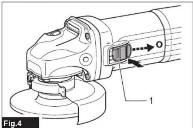
To stop the tool, press down the rear end of the slide switch so that it returns to the "O (OFF)" position.
▶ Fig.4: 1. Slide switch
Accidental re-start preventive function
When plugging in the tool while the switch is ON, the tool does not start.
At this time, the indication lamp blinks in red and shows that the accidental re-start preventive function works. To start the tool, turn off the switch, and turn it on again.
Soft start feature
Soft start feature reduces starting reaction.
Mechanical brake
Only for model GA4541R / GA5041R
Mechanical brake is activated after the tool is switched off.
The brake does not work when the power supply is shut down with the switch still on.
ASSEMBLY
CAUTION: Always be sure that the tool is switched off and unplugged before carrying out any work on the tool.
Installing side grip (handle)
CAUTION: Always be sure that the side grip is installed securely before operation.
Screw the side grip securely on the position of the tool as shown in the figure.
Fig.5
Installing or removing wheel guard (For depressed center wheel, flap disc, flex wheel, wire wheel brush / abrasive cut-off wheel, diamond wheel)
WARNING: When using a depressed center wheel, flap disc, flex wheel or wire wheel brush, the wheel guard must be fitted on the tool so that the closed side of the guard always points toward the operator.
WARNING: When using an abrasive cut-off diamond wheel, be sure to use only the special wheel guard designed for use with cut-off wheels.
For tool with locking screw type wheel guard
Mount the wheel guard with the protrusions on the wheel guard band aligned with the notches on the bearing box. Then rotate the wheel guard to such an angle that it can protect the operator according to work. Be sure to tighten the screw securely. To remove wheel guard, follow the installation procedure in reverse.
Fig.6: 1.Wheel guard 2.Bearing box 3.Screw
For tool with clamp lever type wheel guard
Loosen the screw, and then pull the lever in the direction of the arrow. Mount the wheel guard with the protrusions on the wheel guard band aligned with the notches on the bearing box. Then rotate the wheel guard to such an angle that it can protect the operator according to work.
▶ Fig.7: 1. Wheel guard 2. Bearing box 3. Screw 4. Lever
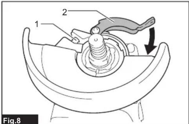
Pull the lever in direction of the arrow. Then tighten the wheel guard with fastening the screw. Be sure to tighten the screw securely. The setting angle of the wheel guard can be adjusted with the lever.
Fig.8: 1. Screw 2. Lever
To remove wheel guard, follow the installation procedure in reverse.
Clip-on cutting wheel guard attachment
Optional accessory
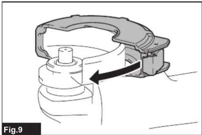
NOTE: For cutting-off operations, a clip-on cutting wheel guard attachment can be used with the wheel guard (for grinding wheel).
Not available in some countries.
Fig.9
Installing or removing depressed center wheel or flap disc
Optional accessory
WARNING: When using a depressed center wheel or flap disc, the wheel guard must be fitted on the tool so that the closed side of the guard always points toward the operator.
WARNING: Make sure that the mounting part of the inner flange fits into the inner diameter of the depressed center wheel / flap disc perfectly. Mounting the inner flange on the wrong side may result in the dangerous vibration.
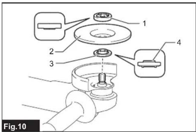
Mount the inner flange onto the spindle.
Make sure to fit the dented part of the inner flange onto the straight part at the bottom of the spindle.
Fit the depressed center wheel / flap disc on the inner flange and screw the lock nut onto the spindle.
Fig.10: 1. Lock nut 2. Depressed center wheel 3. Inner flange 4. Mounting part
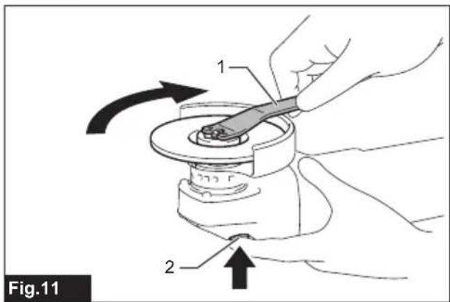
To tighten the lock nut, press the shaft lock firmly so that the spindle cannot revolve, then use the lock nut wrench and securely tighten clockwise.
Fig.11: 1. Lock nut wrench 2. Shaft lock
To remove the wheel, follow the installation procedure in reverse.
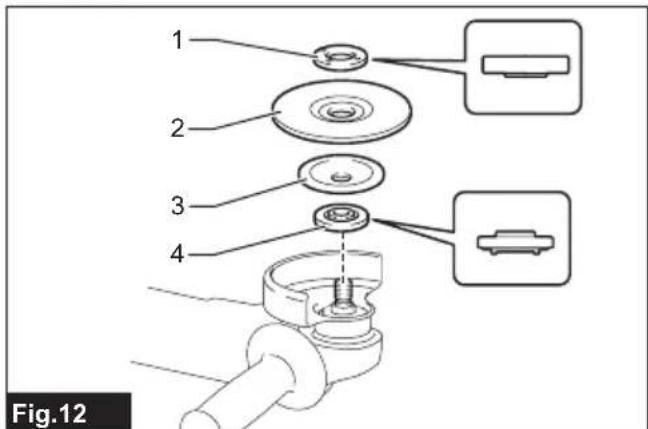
Installing or removing flex wheel
Optional accessory
WARNING: Always use supplied guard when flex wheel is on the tool. Wheel can shatter during use and guard helps to reduce chances of personal injury.
Fig.12: 1.Lock nut 2.Flex wheel 3.Back up pad 4. Inner flange
Follow instructions for depressed center wheel but also use back up pad over wheel.
Installing or removing abrasive disc
Optional accessory
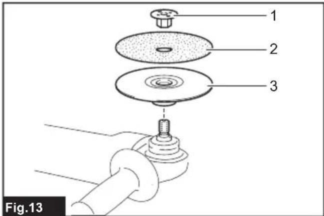
Fig.13: 1. Sanding lock nut 2. Abrasive disc 3. Rubber pad
- Mount the rubber pad onto the spindle.
- Fit the disc on the rubber pad and screw the sanding lock nut onto the spindle.
- Hold the spindle with the shaft lock, and securely tighten the sanding lock nut clockwise with the lock nut wrench.
To remove the disc, follow the installation procedure in reverse.
NOTE: Use sander accessories specified in this manual. These must be purchased separately.
Super flange
Optional accessory
Super flange is a special accessory for model which is NOT equipped with a brake function.
Models with the letter F are standard-equipped with Super flange. Only 1/3 of efforts needed to undo lock nut, compared with conventional type.
Installing or removing Ezynut
Optional accessory
Only for tools with M14 spindle thread.
CAUTION: Do not use Ezynut with Super Flange. Those flanges are so thick that the entire thread cannot be retained by the spindle.
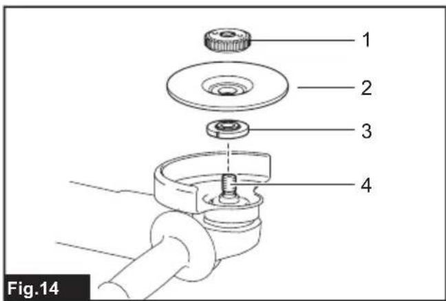
Mount inner flange, abrasive wheel and Ezynut onto the spindle so that Makita Logo on Ezynut faces outside.
Fig.14: 1. Ezynut 2. Abrasive wheel 3. Inner flange 4. Spindle
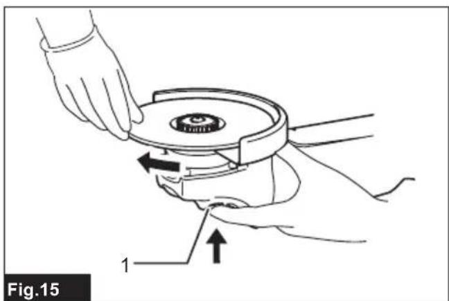
Press shaft lock firmly and tighten Ezynut by turning the abrasive wheel clockwise as far as it turns.
Fig.15: 1. Shaft lock
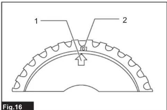
To loosen the Ezynut, turn the outside ring of Ezynut counterclockwise.
NOTE: Ezynut can be loosened by hand as long as the arrow points the notch. Otherwise a lock nut wrench is required to loosen it. Insert one pin of the wrench into a hole and turn Ezynut counterclockwise.
Fig.16: 1. Arrow 2. Notch
Fig.17
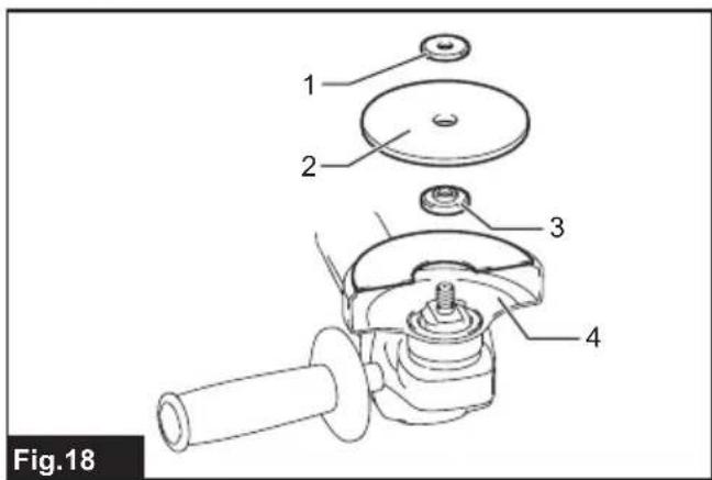
Installing abrasive cut-off / diamond wheel
Optional accessory
WARNING: When using an abrasive cut-off diamond wheel, be sure to use only the special wheel guard designed for use with cut-off wheels.
WARNING: NEVER use cut-off wheel for side grinding.
▶ Fig.18: 1. Lock nut 2. Abrasive cut-off wheel / diamond wheel 3. Inner flange 4. Wheel guard for abrasive cut-off wheel / diamond wheel
As for the installation, follow the instructions for depressed center wheel.
The direction for mounting the lock nut and the inner flange varies by wheel type and thickness.
Refer to the following figures.
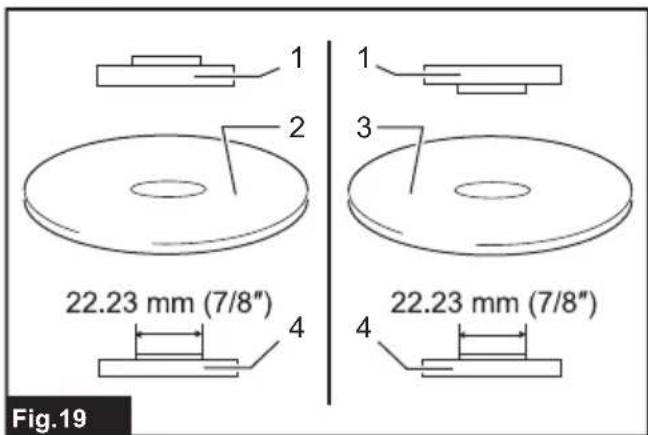
When installing the abrasive cut-off wheel:
▶ Fig.19: 1. Lock nut 2. Abrasive cut-off wheel (Thinner than 4 mm (5/32")) 3. Abrasive cut-off wheel (4 mm (5/32") or thicker) 4. Inner flange
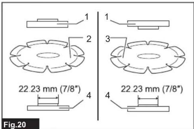
When installing the diamond wheel:
Fig.20: 1. Lock nut 2. Diamond wheel (Thinner than 4mm (5 / 32^ ) ) 3. Diamond wheel (4 mm (5 / 32^ ) or thicker) 4. Inner flange
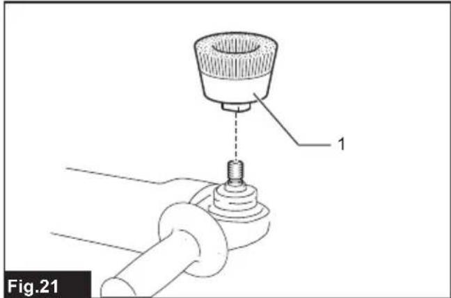
Installing wire cup brush
Optional accessory
CAUTION: Do not use brush that is damaged, or which is out of balance. Use of damaged brush could increase potential for injury from contact with broken brush wires.
Place the tool upside down to allow easy access to the spindle.
Remove any accessories on spindle. Thread wire cup brush onto spindle and tighten with supplied wrench.
Fig.21: 1. Wire cup brush
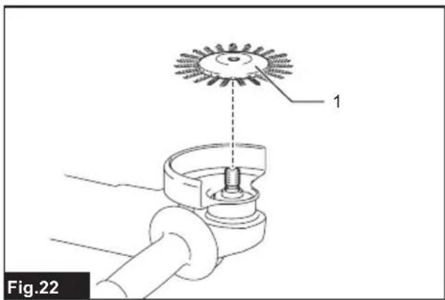
Installing wire wheel brush
Optional accessory
CAUTION: Do not use wire wheel brush that is damaged, or which is out of balance. Use of damaged wire wheel brush could increase potential for injury from contact with broken wires.
CAUTION: ALWAYS use guard with wire wheel brushes, assuring diameter of wheel fits inside guard. Wheel can shatter during use and guard helps to reduce chances of personal injury.
Place the tool upside down to allow easy access to the spindle.
Remove any accessories on spindle. Thread wire wheel brush onto spindle and tighten with the wrenches.
Fig.22: 1. Wire wheel brush
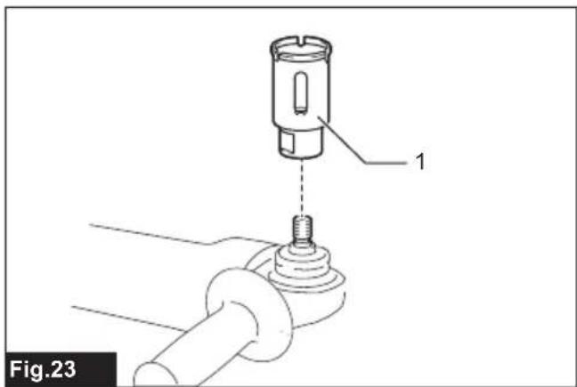
Installing hole cutter
Optional accessory
Place the tool upside down to allow easy access to the spindle.
Remove any accessories on the spindle. Thread the hole cutter onto the spindle, and tighten it with the supplied wrench.
Fig.23: 1.Hole cutter
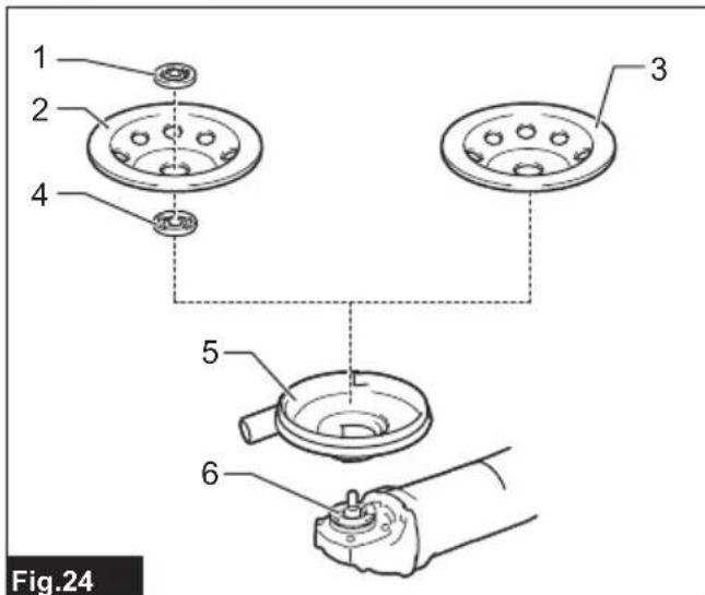
Installing dust collecting wheel guard for grinding
Only for model GA4540R / GA4541R / GA5040R / GA5041R
Optional accessory
With optional accessories, you can use this tool for planing concrete surface.
CAUTION: Dust collecting wheel guard for grinding is only for use in planing concrete surface with a cup-type diamond wheel. Do not use this guard with any other cutting accessory or for any other purpose.
CAUTION: Before operation, make sure that a vacuum cleaner is connected to the tool and turned on.
Place the tool upside down and install the dust collecting wheel guard.
Mount the inner flange onto the spindle.
Fit the cup-type diamond wheel on the inner flange and tighten the lock nut onto the spindle.
Fig.24: 1.Lock nut 2.Cup-type diamond wheel 3.Hubbed cup-type diamond wheel 4.Inner flange 5.Dust collecting wheel guard 6.Bearing box
NOTE: For information how to install the dust collecting wheel guard, refer to the manual of the dust collecting wheel guard.
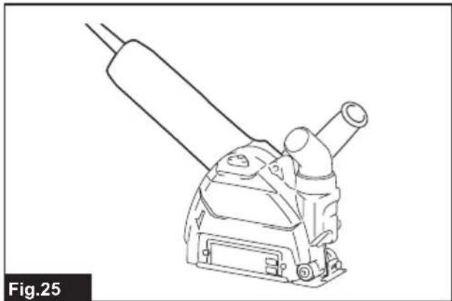
Installing dust collecting wheel guard for cutting-off
Only for model GA4540R / GA4541R / GA5040R / GA5041R
Optional accessory
With optional accessories, you can use this tool for cutting stone materials.
Fig.25
NOTE: For information how to install the dust collecting wheel guard, refer to the manual of the dust collecting wheel guard.
Installing or removing dust cover attachment
Optional accessory
CAUTION: Always be sure that the tool is switched off and unplugged before installing or removing the dust cover attachment. Failure to do so causes damage to the tool or a personal injury.
Install the dust cover attachment to each specified position.
For details, refer to the instruction manual of the dust cover attachment.
NOTICE: Clean out the dust cover attachment when it is clogged with dust or foreign matters. Continuing operation with a clogged dust cover attachment will damage the tool.
OPERATION
WARNING: It should never be necessary to force the tool. The weight of the tool applies adequate pressure. Forcing and excessive pressure could cause dangerous wheel breakage.
WARNING: ALWAYS replace wheel if tool is dropped while grinding.
WARNING: NEVER hit the workpiece with the wheel.
WARNING: Avoid bouncing and snagging the wheel, especially when working corners, sharp edges etc. This can cause loss of control and kickback.
WARNING: NEVER use tool with wood cutting blades and other saw blades. Such blades when used on a grinder frequently kick and cause loss of control leading to personal injury.
CAUTION: Never switch on the tool when it is in contact with the workpiece, it may cause an injury to operator.
CAUTION: Always wear safety goggles or a face shield during operation.
CAUTION: After operation, always switch off the tool and wait until the wheel has come to a complete stop before putting the tool down.
CAUTION: ALWAYS hold the tool firmly with one hand on housing and the other on the side grip (handle).
NOTE: A dual purpose wheel can be used for both grinding and cutting-off operations.
Refer to the "Grinding and sanding operation" for grinding operation, and refer to the "Operation with abrasive cut-off / diamond wheel" for cutting-off operation.
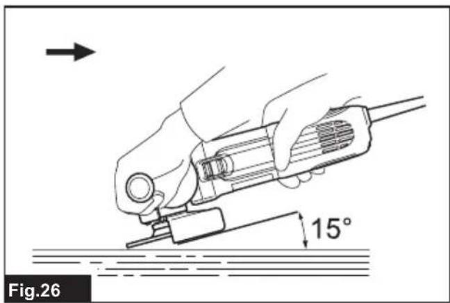
Grinding and sanding operation
Fig.26
Turn the tool on and then apply the wheel or disc to the workpiece.
In general, keep the edge of the wheel or disc at an angle of about 15^ to the workpiece surface.
During the break-in period with a new wheel, do not work the grinder in forward direction or it may cut into the workpiece. Once the edge of the wheel has been rounded off by use, the wheel may be worked in both forward and backward direction.
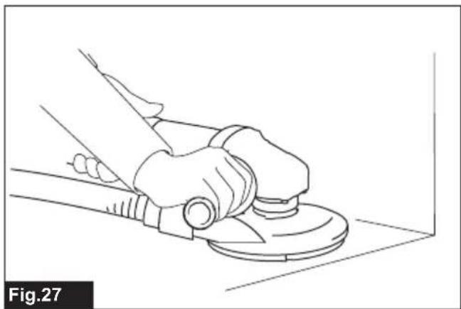
Usage example: operation with cup-type diamond wheel Fig.27
- Keep the tool horizontally and apply the entire cup-type diamond wheel to the workpiece surface.
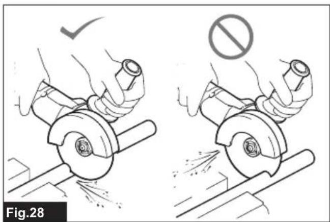
Operation with abrasive cut-off / diamond wheel
Optional accessory
WARNING: Do not "jam" the wheel or apply excessive pressure. Do not attempt to make an excessive depth of cut. Overstressing the wheel increases the loading and susceptibility to twisting or binding of the wheel in the cut and the possibility of kickback, wheel breakage and overheating of the motor may occur.
WARNING: Do not start the cutting operation in the workpiece. Let the wheel reach full speed and carefully enter into the cut moving the tool forward over the workpiece surface. The wheel may bind, walk up or kickback if the power tool is started in the workpiece.
WARNING: During cutting operations, never change the angle of the wheel. Placing side pressure on the cut-off wheel (as in grinding) will cause the wheel to crack and break, causing serious personal injury.
WARNING: A diamond wheel shall be operated perpendicular to the material being cut.
Usage example: operation with abrasive cut-off wheel Fig.28
Usage example: operation with diamond wheel Fig.29
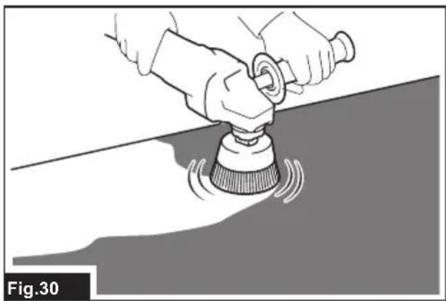
Operation with wire cup brush
Optional accessory
CAUTION: Check operation of brush by running tool with no load, insuring that no one is in front of or in line with brush.
NOTICE: Avoid applying too much pressure which causes over bending of wires when using the wire cup brush. It may lead to premature breakage.
Usage example: operation with wire cup brush
Fig.30
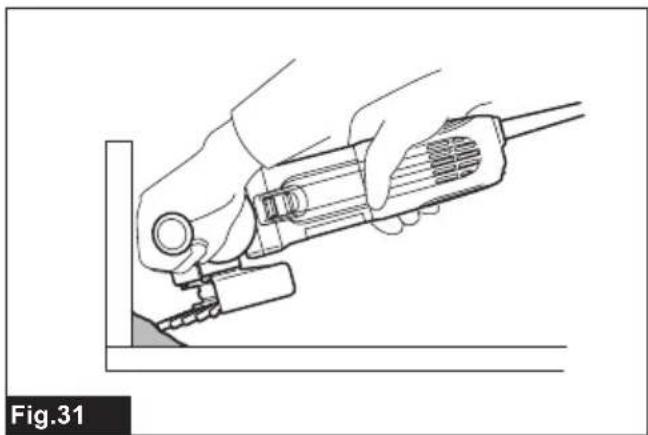
Operation with wire wheel brush
Optional accessory
CAUTION: Check operation of wire wheel brush by running tool with no load, insuring that no one is in front of or in line with the wire wheel brush.
NOTICE: Avoid applying too much pressure which causes over bending of wires when using wire wheel brush. It may lead to premature breakage.
Usage example: operation with wire wheel brush Fig.31
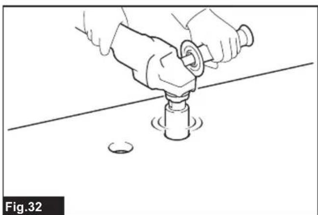
Operation with hole cutter
Optional accessory
CAUTION: Check operation of the hole cutter by running the tool with no load, insuring that no one is in front of the hole cutter.
NOTICE: Do not tilt the tool during operation. It may lead to premature breakage.
Usage example: operation with hole cutter Fig.32
MAINTENANCE
CAUTION: Always be sure that the tool is switched off and unplugged before attempting to perform inspection or maintenance.
NOTICE: Never use gasoline, benzine, thinner, alcohol or the like. Discoloration, deformation or cracks may result.
To maintain product SAFETY and RELIABILITY, repairs, carbon brush inspection and replacement, any other maintenance or adjustment should be performed by Makita Authorized or Factory Service Centers, always using Makita replacement parts.
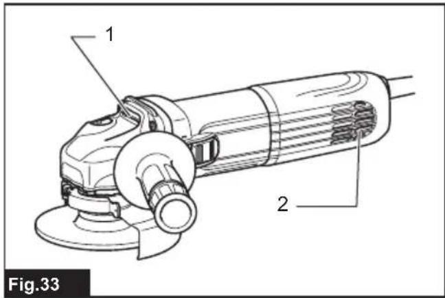
Air vent cleaning
The tool and its air vents have to be kept clean. Regularly clean the tool's air vents or whenever the vents start to become obstructed.
Fig.33: 1.Exhaust vent 2. Inhalation vent
COMBINATION OF APPLICATIONS AND ACCESSORIES
Optional accessory
CAUTION: Using the tool with incorrect guards can cause risks as follows.
- When using a cut-off wheel guard for facial grinding, the wheel guard may interfere with the workpiece causing poor control.
- When using a grinding wheel guard for cutting-off operations with bonded abrasive wheels and diamond wheels, there is an increased risk of exposure to rotating wheels, emitted sparks and particles, as well as exposure to wheel fragments in the event of wheel burst.
- When using a cut-off wheel guard or grinding wheel guard for facial operations with cup-type diamond wheels, the wheel guard may interfere with the workpiece causing poor control.
- When using a cut-off wheel guard or grinding wheel guard with a wheel-type wire brush with a thickness greater than the maximum thickness as specified in "SPECIFICATIONS", the wires may catch on the guard leading to breaking of wires.
Use of dust collecting wheel guards for cutting-off and facial operations in concrete or masonry reduces a risk of exposure to dust. - When using dual purpose (combined grinding and cutting-off abrasive) flange mounted wheels, only use a cut-off wheel guard.
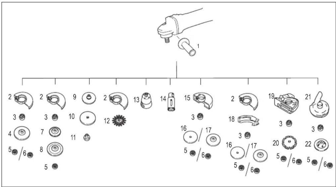
| - Application | 115 mm model 125 mm model | model 150 mm model | ||
| 1 - Side grip | ||||
| 2 - Wheel guard (for grinding wheel) | ||||
| 3 - Inner flange / Super flange *1*2 | ||||
| 4 Grinding / Sanding Depressed center w/ wheel / Flap disc | ||||
| 5 - Lock nut | ||||
| 6 - | Ezynut *1*3 | |||
| 7 - | Back up pad - | |||
| 8 | Grinding | Flex wheel | - | |
| 9 | - | Rubber pad 100 | Rubber pad 115 | Rubber pad 125 |
| 10 | Sanding | Abrasive disc | ||
| 11 | - | Sanding lock nut | ||
| 12 | Wire brushing | Wire wheel brush | ||
| - Application | 115 mm model 125 mm model | 150 mm model | ||
| 13 Wire brushing Wire cup brush | ||||
| 14 Hole cutting Hole cutter | ||||
| 15 - Wheel guard (for cut-off wheel) | ||||
| 16 Cutting-off Abrasive cut-off wheel / Diamond wheel | ||||
| 17 | Grinding / Cutting-off | Dual purpose wheel | - | |
| 18 - Clip-on cutting wheel guard attachment *4 | ||||
| 19 | - | Dust collecting wheel guard for cutting-off *5 | - | |
| 20 | Cutting-off | Diamond wheel | - | |
| 21 | - | Dust collecting wheel guard for grinding *6 | - | |
| 22 | Grinding | Cup-type diamond wheel *6 | - | |
| - | - | Lock nut wrench | ||
| - | - | Dust cover attachment | ||
NOTE: *1 Do not use Super flange and Ezynut together.
NOTE: *2 Do not use Super flange with a grinder equipped with a brake function.
NOTE: *3 Only for tools with M14 spindle thread.
NOTE: *4 Clip-on cutting wheel guard attachment is not available in some countries. For more details, refer to the instruction manual of the clip-on cutting wheel guard attachment.
NOTE: *5 Only for model GA4540R / GA4541R / GA5040R / GA5041R
For more details, refer to each instruction manual of the guard.
NOTE: *6 Only for model GA4540R / GA4541R / GA5040R / GA5041R
For more details, refer to each instruction manual of the guard.
OPTIONAL ACCESSORIES
CAUTION: These accessories or attachments are recommended for use with your Makita tool specified in this manual. The use of any other accessories or attachments might present a risk of injury to persons. Only use accessory or attachment for its stated purpose.
If you need any assistance for more details regarding these accessories, ask your local Makita Service Center.
- Accessories listed in "COMBINATION OF APPLICATIONS AND ACCESSORIES"
NOTE: Some items in the list may be included in the tool package as standard accessories. They may differ from country to country.
SPÉCIFICATIONS
ACCESSIONS EN OPTION
VEILIGHEIDSWAARSCHUWINGEN
OPTIONELE ACCESSOIRES
▶ Fig.4: 1. Interruptor desizable
| Modelo | Emissão de vibração (ah,AG) : (m/s2) | Incerteza (K): (m/s2) |
| GA4540R 6,0 1,5 | ||
| GA4541R 6,0 1,5 | ||
| GA5040R 6,0 1,5 | ||
| GA5041R 6,0 1,5 | ||
| GA6040R 6,0 1,5 |
Sikkerhedsadvarsler for slider
Kun for model GA4541R / GA5041R
Fig.8: 1. Skrue 2. Arm
Fig.16: 1. Pil 2. Hak
Fig.17
Kun for model GA4540R / GA4541R / GA5040R / GA5041R
Ekstraudstyr
Kun for model GA4540R / GA4541R / GA5040R / GA5041R
Ekstraudstyr
BEMAERK: *6 Kun for model GA4540R / GA4541R / GA5040R / GA5041R
Móvo yia xwpe ts Eupwnns
Oi Anwosicuupoppwong Tepiaaavovta oTnapaptnma A stpov yxepidio odnyiw.
IPOEIAOIOIHSEIEA ΣΦΑΛΕΙΑΣ
Evikeoioeic a0aiayia to nEKTpiko epyaieio
A PPOEI OIOIH Hiaaote oaes TIG PPOE I
oioinoeic aoaaleiac, odnyiec, EIKOVoypaonoeic
kai npoiaypaoec nou npexovtai e auto to nKtpiko epyaleio. H un npon oawv twv oywiw TOU
avayapovtai katwetpw mtopei va kataanxi e ne kTpoTTnla, Tupkayia n/kai oobapo tpaumatio.
UαTe oεC TIG POεiδoToin-σει KAI TIG OηyεC YIA μελIoVTIKn TAPaTouπn.
TIC TPOEIDOTIOAEOI, O oOc avaepetai e 9nEKTPOKO EPAAEIO TTou TPOPOBTeiTai ano TIV KUPIA TAPoxn nEeKPTIKOU PEUMATOC (eNtPko KaWio) n eNtPko EpyAeioTTou TPOPOBTeiTai ano MTatapia (wpiC NkTPOKO KaWio).
PpOeIoboTnOeIc aOgaaIaIg yia Tov λειavTnpa
PnoeioToinoei aqaaiea, koiEvc yiaepyaoic aeavons, yuaoxapriato, kaapou u eoupauoouptoa n atokotns:
- AutoTo nAekptikO epyaaleio Tpoopicietaia xpnoa Wc epyaaleio laivons, yuaoxapitioatoc, kaepioueupuatoBoutaa, TnnpotpuTavou n aTkoTnC. diaabeT oLc TIC TPOeIOToIOnEIG aOpaaleios, Odyiec, EIKOVypqneic KAI TPObiaypae cTou TApexovtai e auto To nAekptikO epyaaleio. H un npon oawv twv odnyiw Tou avaypaovtai katwepw mTopei va kataanE i e NAEKtpoTAnSia, TUPKayia /kai oobapo Tpaumatio.
- npETeIvaekTeAeToouvepyaOiesoTIAW- Ons 1e auto to nEeKTPIO EpyaEio.AeIoUpyie G YIA TIG OTIOEc auto TO nEeKTPIO EpyaEio DEv Exei OxEiaOTei mTOpEi va dNmuOpynOauV Kivduvo Ka Va TTPOKAeOauv TPOaONIK Tpaumatio
- Mny npaymuatoioitee metatpontc oe auto to nektpikó epyaleio me tpoTTOU 8ev exei eIDika oxediataei n kaopiotei anTo tv kataokeuotn tou epyaleiou. Mia teoia metatpottn mtopei va exei aTATEAeou Tnv atwleia eEyyou kai va Tpoka- aeoi oobapo TPOOWTIKO Tpaumatiao.
-
Mny xpnoiopoioite EapntmaTnou evivai Eikia oxediouva kai kaohopiovta aTTOV kataoKEuaotn Tou epyaieou.AAWCai mvo tEeIDnTo Eaptnma uTopei va TPOOAPTN0I OTO nAektpiko epyaieio, auto dev eaaqpaaiceiaopaaIh Aetoupyia.
-
H ovopaotikn taxutnta tou eaptnmuo ts pe TNI VA Eiva Toulaxiotov ion ME TNV MEYIOTN Taxutnta Tou Eiva OneuwevN OTO Nkptko Epyaleio. Eapntmuata TPO Aetoupyouv taxutepa aTNO vOvopaotikn taxutnta Touc MTopei va OTAOOV KAI VA EKTOEuvOv.
- H E\xi TEPIKn i ETPOs KAI TO TAPXOS TOU EApTnmuTOSa TPEIE VA Eivai MEoσ OTA opia IKavOTNTAC TO NLEKTPIKOU EPyAeiou OAc. EApTnmuTAAvOaμevou μEyEoUs δv μTopoUV va TPOpuaXoUV n VA EeYxOuv ETAPKwC.
- OI diaoTaeic TcS oTepewongc Eapntmuos Tpentei va taipiazouv ME Tc diaoTaoeis Tou EoTnlaou OTepewongtou nEeKtpikou Epyaleiou. Ta eapntma Tou dev taipiazouv ME To Eeaptnma OTepewongtou nEeKtpikou Epyaleiou 0a napouiaouuv UToBaaouevn Cuyoataoian, UTepeBoIAIOUC Kpaaoouc kai Evexoyewoc atwleia eelyxou.
- Mny xnpoiuotoeiEgaptnua Tou exi unootei .Piiv ano kaeXpno,va Egeatazete to eaptnua, otwns aeavitikouc tpoxouc, ia piviaata kaipwye, tn bao n uonotnpieng yia pwye, pnng n utepolikn oop, tn oupatobouptra yia xaapanpayioeva oupata.Av to nAektpko epyaaleio nto esaptna Teoei katw, eayote to yia znuiec nTPOAPoote eva kaLo eaptnma.Met aTov eayxo kai Tnv TPOAPooyn evoc eapntmuatoc, atoukaKpuveite eoeic kai oi yupw oac atto TETTEO Peipotpoqnc Tou eaptnmuatoc kai apnoTe OE toupyia to nAektpko epyaaleio oe myiotn taxutnta Xwpic qoptio yia eva AETIO.Egaptnata me Znuiec thadiauohov kataov xpvo autnc tsdokimns.
- Na φopate Εξοπλισό o atοικής προσταίας. Avaloya με την εφαμουγ, va χροιμοτοίeτι προωπιδα προσταίας, προσταυτικά γuαλί-προωπιδες ἡ yuaλί προσταίας. Šταν απαιτείαι, va φopate μασκα σκόνης, προσταυτικά ακός, γαντία κι Φόβα συνεργέιου έκανα va παρέχουν προσταία από τα εκτίνασόμενα μικρα θραύμata λόγω της λείανός ἡ του τεμαχίου εργαίας. Ta προσταυτικά ματιών πρεπείν αεῖαι έκανα va σταμatησουν tuxóv εκτίνασόμενα θραύμata του δημιουρούνται kata την εκτέλεόη διφόρων εφαμουγών. H μασκα σκόνης ἡ αναινεισηρας πρεπείν αεῖαι κανήν αφιλράρει σωμαιδία έπου πραγονται από τη συγκερίμενη εφαμουγή. H πρατεταμένη εκθεόη σε Εόρμοθο υμηλός ενταόng μπορείν απροκλέσει απιλεία ακόός.
- Kpatate Touc yupw oac oe ia aopaa n ano-
Otaon anro Tox wpo epyaiaoc. Otoiooohntote
EIOEPXoEvoc 0To Xwpo epyaiaoc PpETeI
va popa atoukio TPOOTATEUTIKO EOGTIAOu.
Teuxiaa anro To Teuxio epyaiaoc n anro eva
Otnaoevo EApntma uTOpei va EKtivaxoov
pakia kai va Tpokaleosouv Tpaumatoo Pepav
tns aleons TEPioxns epyaiaoc. -
Kpatate To nAekptiko Epyaaleio mOvo aTIO TIC MOVwueves ETIAPVEK kpatnmuotc,OTAV EKTAEITE MIA Epyaia OTOU TO ESAptnma KOITNS MTOpEi VA EPoE iEETAPH NkpumuVEc KAawoiwoeis nE To DIKO Tou KAawio. ZTE PEPITTOWI ENAqns Tou Eapntmuatc KOITNS ME nAektpofo KaWIO, MTOpE ta EKTeEIEVA UETAALIKA EApntmuata Tou nAektpkoU epyaaiou va kataoouv Ta iDIA nAektpofo pa Kai va TpokaAeouv nAektpoTTAnGia oTo XeiPiotn.
-
KpatnoTe To kaawio pakia aTo Tpei OTepeoEvO EApTnua.AV XaoTe Tov ELevXo, To Kaawio Tpoopooiaac mTOpE iVa KOTei n va EITAAkei kai To xepi n o Bpaxiovac oac mTOpE va TpaBnxti TPOC TO TEPIOTpeoEvO EApTnua.
- Mny aqivete note to nektpiko epyaaleio katw, piv otapatnoe i npw c n tepiotppon tou egaptmuo. To nepiortpefoevo esaptma o va Tiaoei Tnv Etnipaveia kai va TpaBnei to nektpko epyaaleio eomega ato tv eayxo ag.
- Mny xepiote To nAekpiko Epyaiao Evw To metapepet OTO AEPUO aC. Tuaia eTAPn eTo TEPIOPEPOevo EApTNmu TIOpEVA TPOKAeaei TIAIO oTa pouxa oac kai va TpaBnEto EApTNmu eo aTo oWma aC.
- Kaθapiετε TAKIKA ta avoiyμata εαερισοu Tou nλεκτριού εργαλείου. O avεμισηρac Tou μοτερ θα αναρροφησει τη σκόνη μεσα στο περβλημα κai n utερβολικη σουκεντρωση πισματων μεταλλού μτορείνα προκαλεσει κιδυνο nλεκτροπληξίας.
- Mny xepiEeTo nAektpko epyaiao KovTa oE uqAekta uIAka. OITIVnpeC mTopei va TpokaAeouv avapAeN autwTwv uikwv.
- Mny xpnoiopoioite Eepntmuata Tou xpeia- Zovta iyuktiKa uypa.Hxpnoy evpou n aaawv yuktkow uypw vTOpE va TpokaAeoi nAektpoTTnxi a nok.
KlOToNa kai oxTeiKeS pOeIoToOnioEoi:
To klotanega eivai iia faqvikn avtidaon tou epaieou Aoyw ouoqiyng n okaawmuotc Tou TEPiOTpepoevou tpoxou,tns Baoang utooTnpigns,tns BouOtaoc n tuxov aalou eapntmuatc. H ouoqiyn n to kaawma TPOkalei taxaia atwaleia eEyyou Tou TEPiOTpepoevou eapntmuatc to otioio stn ouvexia utoxpeewei to aveEeYKTO nAektpiko epyaaleio OE TEPiOTpOg n avtietn ato Eeivn Tou eapntmuatc oTo onueio EumloKnc. Ia Tnapadeiyua,av evac leavitikoc TPOXCS TEPIEALeI O e ouoqiyn n okalomega aTo TEpaixio epyaiaag, n akun Tou tpoxou Tou Etepxetai oTo onueio ouoqiyng mTOpei va okaeivtnv ETiPaveia Tou ulikou TPOkawvtac Tnv avatihonn to klotanega Tou tpoxou. O tpoxoc mTOpei va avatihonnoi TPOC TO Mepoc Tou xeipiotn n avtihtera va atopakpvthetai atto autov, avaloya e tn qopa TEPiATPOPNC Tou tpoxou oTo onueio ouoqiyngs. Ytio autec tic ouvthkec,oi LEAVTIKOI TPOXIOTeTIOG VA UTOOUv 0paun. To klotanega eivai aTOTeLaeogkaKnc xphongn /kai epaalveuvdiabikaaiuvn suuvthkwv xepiouou Tou nAektpkoU epyaaleiou kivai duvatov va attopeuxthetai laubavovtac katallnaes TPOpuAaeic, OTWSC TEPiPypovtaikatwTePW.
- Kpatate Otaepa to nEeKtpio Epyaleio kai e Ta duo xepia kai TOToBETnoTe TO oWma kai Touc Bpaxioe c aac etoi wote va avthetaavai OTIS Duvapeic tou kLoToHmuato. Na xpnoiopoIe iTavta BonOtnikn Aabn, na TAPexetai, yia Mevioto BaOmu ELeyxou tou KLoToHmuato n TnC potncs avtibpaonk kat a Tnv EKKivnon. O xei-piotnc mIopei va ELeyXei TIC avtibpaoeic potncn h Duvapeic kLoToHmuato, av exouv AnpOei oI kataa-
-
Noté μη βαλετο TO xέρι σας κοντα στο Περιστρεφόμενο εξάρτημα. To εξάρτημα μπιρείνα κλοτοήσει στο xέρι σας.
-
Mn toTOnToeTneTo oWma Oac OTNV TEPIOXn 0Tou To nAektpiKo Epyaleio 8a KIVnTei av ouBei KaToMa.To KaToMa 8a OdynoeI To Epyaleio 6 dieuovon AvtiEtn Tc KivnOng Tou Tpoxou OTO Onmuio EPTAOkns.
- Pooexe Tiaepa oTav epyaceote e ywies, aixunpa akpa, kT. Na anopoeuyete tnv avanbnonkai to okalwaou Eapntmuotc. Wvies, aixunpeacke n avattnoaeic exouv tnvaon va Tpokalov EPTLOKn OTO TEPOTPEOevo EAp-tnma kai Tpokalov aTTWEA iExyou n KLOTOnma.
- Mny TPOOAPUOZTe aAUoONPiOvo, AETIIDA gULOyAUTTIKns, TUNaTko DIAuVTOPxO Me TEPiPePEIAKO KEVO MEYALUTePo aTO 10 mm n OBOVtwn AETIIDA TPOIOU. TeTOIEs AAEsc TPOKAoUV Ouxv KLOTOnma KAI ATWAAEA EEyxou.
PnoeioToinoeic aopaaiae iikya yia epyaiec aeavonkai atokotns:
- Na xpnoiiooieite movu tuouc tpoxwv Tou Ka0opioVtai yxno n e To diko oac nKtpko epyaaleio kaowc kai tov ouykepigevo Tpoquulaktnpa Tou exei oxediaotei ia Tov EIIeYmuvo Tpoxo.H npoxn eTapkouc Tpo- taia c aTOPOXOUC YIA TOU C OIOUc DEV ExeI oxediaotei To Nektpko epyaaleio,Dev evai duvat KAI ETOVEWc oI TPOXOI DEV EVAI aopaaleic.
- H Eπiφανειλειavος των τροχών με χαμηλω- Μενο Kéντρο πρεπειν ειδι αστερεωμένη κατω ατότο επιπεδο tou προστατeutikou xειλους. 'Evac tpoxóς τοῦ ενια iστερωμένος kaá o o tioioc πρoεξεχει μεσα ατότο επιπεδο tou προστατeutikou xειλους δεν μπορείν απροστατeutéι επιαρκως.
- H TpOoapuoyn Tou TpOoUaktnpa OTo nE-KTpiKo EpyaEio TpeTcIva TpaymuToTOieiTai Me aOpaaleia KAI N TOToTHetOn Tou VA TApExeITn MeyiToN Duvatn TPOoTaia, Wote EaXIOTo TMnau Tou TPOxou VA EKTIEeai TPOC To MePoc Tou XeiPiOn. O TpOoUaktnpac DIEukoLvvi Tnv TpOoTaia Tou XeiPiOn aTIO OTaoueV a Pau- OmaTa Tou TPOxou, TUxaia Etapn ME TOv TPOxo Ka OTVHnepc Tou MTPoOpvva TpOKaEsoov Tnv avaFxgnpouioou.
- OI tpoxoi IpiEe va xpnoiouoivai mov O TIC KAOTOIEVEc EAPUoyEc. Ia npapdeiyma: n aeiaiveTe ME TnV PLEUPIKN ETIPAVEAIO TU OTOXOU aTOKOTnC. OI tpoxoi AIAVONc antoKOTnC TPOOPICIOTAI VIA TEPiPePEIAK N AEIAVON, n EAPUoyn TLEUPIKW DuvAeewv OE autouc Touc TPOXOUc MTOpei va TpOKaLaeoi Tgpaun Touc.
- Na xpoiopoioite Tav aXavTcTPOxWv Tou dEv exoov UTOOTEI bAaBn Kai eivai kataa- Anlou eYeBouc KAI oxmuos yia Tov EIIeY- Mevo TPOxo. OI kATAANAE cXavTcE TPOxWv UTOATnpizouv Touc TPOxOc KAI eIWovuE ITOpE- VwC TIV TIaovotna 0pauncs Touc. OI XAVtEc TWV TPOxWv ATOKOTNC MIOpei va BIApepov aTTo TIC XAVTcE Tuv TPOxWv AEiavOns.
-
Mv xpnoiotnoie t 0apueovc tpoxouc aTIO eYaalutepa nEeKtpia epaaleia.Eva TPOXOC Tou TPOoPiZetai yia xpion e eva eYaalutepo nEeKPTIko Epyaleio dEv iivai kataaanoc yia tvuynalotepn taxtnta evoc mikoTepu epyaaleiou kai mtopei va uttoatei pauon.
-
Otav xpnoiuotoiieTrepoxouc diIauo uKoTou, va xpnoiuotoiieTre naVTo Tov oWto TPOUlambda npa yia Tny eapuoyn Tou EkTeAeitai. Av dev xpnoiuotoiinote ToV oWto TPOUAAKTnpa, mTOpei va mnu exTe ToV ETIOUNTO BAto TPOStaiaC, vEvovoc Tou mTOpei va Odyne i 0e 0oBapop Taupatio.
Móvo yia to muvélo GA4540R / GA4541R / GA5040R / GA5041R
NpOaipTeIkoEgApTnua
Me TPOaipetiké agptnmuata, mTopeite va xpnaioutoi n oTe auto To epyaieio yia To TTAvioa ETIKpavieic atro OKupodεμa.
A PPOOXH: To pooatateutiko oulloyns oKovns tpoxou yia tov ekkevtpo diaaavtotpoxo xpnoiopoitoeiata mvo yia to Tlaviogma etiaveia c ano skupodepa me ekveTpdoiaavtotpoxo. Mn xpoiopoioiote auto to pooatateutiko e ottoiohntote aallo egaptnka kottnc n ia otoiov- hntote aallo okoTtio.
A PPOOXH: Piv aTn Tn aeitoupyia, Bepai- wthe oTI exei ouvdethetai nektpikn okounta oTo epyaleio kAI OTI eiva evpyoToinjev.
TOnToeTnOte To EpyAeio avAntoKaai TOnToeTnTe To TPOoTaTeutiko ouAoync OKovnc Tpoxou.
ΣTEPEWOTE TIV EOWTEPIK ΦΑVCTa TAVW OTNV ATPAKTO.
Epaopoe TOV diaavotpoxo TUOTKouTACOTNV EOWTEPIKn PAAVTCA KAI OpiTe TO TAgIaIaIaT NAV OTNv ATpAKTO.
Eik.24: 1. Naigai aopaiang 2. iiaavto poxoc tuou koutac 3. iiaavto poxoc tuou koutac me nivn 4. Eaotepi kn avtca 5. Pooatautiko ouooyng okovnc poxou 6. Kjwio epaonc
NAPATHPHSH: Ia nnpoopoeic oxetikaeTov TpOIO TOIOteINcTOU TPOoATEUTIKOU OAUOyns OKoVnC TPOXou, avatpeEeTcOTo EYxepidio Tou TPOoTaTeUTIKOU OAUOyns CKoVnCS TPOXou.
ToTROETNON TPOOTATEUTIKOu OuaLoyns OKovns TPOXou Yia aTOKoTn
Móvo yia to muvτélo GA4540R / GA4541R / GA5040R / GA5041R
Pnoaipetiko eaprtma
Me TPOaipetiké EApntmuata, MTOpeite va XpnoiPoTOnI- OTe auto To Epyaaleio yia Tnv KOtt NtETpiWv UAIkwv.
Eik.25
NAPATHPHSH: Ia nnpoopiec oxetik aev tov tpoTtoTtntnCtou TPOoTateutiko ouuauyns oKovnc TPOXOU, avatpeEeT OTo EYxepidio Tou TPOOATeUTIKO uuuoync oKovnc TPOXOU.
ToTtoTeTnon n aφaipεoN tou TPOOaPTnμaTOG KAλuμaTOG OKovng
Ipoaipetiko eapntma
A INPOOXH: Na ebaiwveote navta ot to epyaieio eivai aTVEpyoToinmu KAI aTOnouv- dEdepevo TIV TOTOETnOeTe n aPaipeoTe To TPOaaptma KaUmuatoc OKovnc. Av dev TO KAVETe auto, 0a TpokAne IBaBn oTo epyaieio n TpooWtiko Tpaumatioc.
ToTOnoTeTnTo TPOaApTnMa KaAuMuAtos OKovnOe KαθεKaθopiaμevn θεa.
TIA λETToupeEies,avatpEte OTO EYxεIpio oOnyiw Tou
TPOaapTnAtos KaAuMuAtos OKovnC.
EIAONIOHs:KathetaToTPOaPTnkaUmuoScKovncotavivaippayevoe Oskovn hEvuaikac HuvexncAeioupyiaeppayevo TPOaPTnkaUmuatoScKovncOpaKaaleeBaaN oTo epyaleio.
AEITOYPTIA
A NPOEIAOIOIH: ev 8a TpeTeI Tote va
eaokeite uTepboiikn duvaun oTo epyaleio.To
Bapoc tou epyaaleiou apapuocie apkcttnieon. O
eavaykaosoc kai n utepboiikn tiieon mTopei va
TPokaiaoeuv tIKivduvo OTAOIO TU TPOXOU.
A NPOEIOH: Na avtikaiotate I NANTA TOV Tpoxoav To epyaio TTcKtawKaTaTn Aeiavon.
A NPOEIAOIOIH: Mn xTuTATE NOTE Tov TPOXo ETTAVW OTO TEuaxio EpyaiaC.
A PPOEI OIOIH: ATOOuyET Tc avattno- OEIG KAI TOIIMnmuT aou TPOXOU, IDaitepea otav Epyaceote TAVW OE YwVIEC, aIXmpec AkpcKAT. Auta MTopei va TpokaEeouv aTTwAia ELeyxou KAI TIVaymu TPOG Ta Tio
A NPOEIOHOIHsH: Mn xpnoiopoioite NOTE TO Epyaleio ue alec kontns fulou kai aapa Tpioviou. Teoic alec otav xpnoiopoiouvtai ouxva OTov aeivtn tpokaouv atwleia eEyxou aTO ta TIVaymuata kai oynouv OE poootikopaupatio.
A INPOOXH: Mn θετεποτe to εργαλεio σε λειουρία ὄταν βρισκεται σε επαφή με το τεμάχοι εργασίας επειδόν μιθοείν α προληθεί τραματι-σμός του χερισή.
A NPOEXH:KataTn diapkeia Tns aeitoup-yias,va φopate navta pootatetuká yuaia n Tpoootida.
A PPOOXH: Meta tn aeitoupyia, va obnvete TnVTA TO epyaaleio kai va TepiEvete mexoI O ToPoxocva otapatnoeIT eaiwC piv afoetekatw to epyaaleio.
A INPOOXH: Na Kpatate NANTA to εργαλεio σταθερα με to ενα θερι στο περιβλημα και με to αλλο θερι στην πλάγια λαβή (λαβή).
NAPATHPHSH:Evac tpoxoc dttAnxc xponc mtopei va xpnoiotoine i yia epyaiec Aiaovonc kai atokotn.
AvatpeTe OTnv TnpaypaO «Aeitoupyia troxioaTOc kai AevanS» VIA TNV Epyoia AieavonC kai OtvN TnpaypaO «Aeitoupyia e Tpoxo AieavonC aTOKOTnC / diauavTPOXO» VIA TNV Epyoia aTOKOTnC.
Aeitoupyia troxioaatoc kai aeivong
Eik.26
OeTe To epyaIeio e aeitoupyia kai t a epapuoTe Tov Tpoxo n to diao oTo TEaXIO epyaiaac.


- Symbols
- Intended use
- Power supply
- Noise
- Vibration
- Declarations of Conformity
- For European countries only
- SAFETYWARNINGS
- General power tool safety warnings
- Save all warnings and instructions for future reference.
- Grinder safety warnings
- Kickback and related warnings:
- Safety warnings specific for grinding and cutting-off operations:
- Additional safety warnings specific for cutting-off operations:
- Safety warnings specific for sanding operations:
- Safety warnings specific for wire brushing operations:
- Additional SafetyWarnings:
- SAVE THESE INSTRUCTIONS.
- FUNCTIONAL DESCRIPTION
- Indication lamp
- Shaft lock
- Switch action
- Accidental re-start preventive function
- Soft start feature
- Mechanical brake
- ASSEMBLY
- Installing side grip (handle)
- For tool with locking screw type wheel guard
- For tool with clamp lever type wheel guard
- Clip-on cutting wheel guard attachment
- Optional accessory
- Installing or removing depressed center wheel or flap disc
- Installing or removing flex wheel
- Installing or removing abrasive disc
- Super flange
- Installing or removing Ezynut
- Installing abrasive cut-off / diamond wheel
- Installing wire cup brush
- Installing wire wheel brush
- Installing hole cutter
- Installing dust collecting wheel guard for grinding
- Installing dust collecting wheel guard for cutting-off
- Installing or removing dust cover attachment
- OPERATION
- Grinding and sanding operation
- Operation with abrasive cut-off / diamond wheel
- Operation with wire cup brush
- Operation with wire wheel brush
- Operation with hole cutter
- MAINTENANCE
- Air vent cleaning
- COMBINATION OF APPLICATIONS AND ACCESSORIES
- OPTIONAL ACCESSORIES
- ACCESSIONS EN OPTION
- VEILIGHEIDSWAARSCHUWINGEN
- OPTIONELE ACCESSOIRES
- Sikkerhedsadvarsler for slider
- IPOEIAOIOIHSEIEA ΣΦΑΛΕΙΑΣ
- Evikeoioeic a0aiayia to nEKTpiko epyaieio
- UαTe oεC TIG POεiδoToin-σει KAI TIG OηyεC YIA μελIoVTIKn TAPaTouπn.
- PpOeIoboTnOeIc aOgaaIaIg yia Tov λειavTnpa
- KlOToNa kai oxTeiKeS pOeIoToOnioEoi:
- PnoeioToinoeic aopaaiae iikya yia epyaiec aeavonkai atokotns:
- NpOaipTeIkoEgApTnua
- ToTROETNON TPOOTATEUTIKOu OuaLoyns OKovns TPOXou Yia aTOKoTn
- Pnoaipetiko eaprtma
- ToTtoTeTnon n aφaipεoN tou TPOOaPTnμaTOG KAλuμaTOG OKovng
- Ipoaipetiko eapntma
- AEITOYPTIA
- Aeitoupyia troxioaatoc kai aeivong
Brand : MAKITA
Model : GA5040R01
Category : Garden shredder