MAC610 - Compressor MAKITA - Free user manual and instructions
Find the device manual for free MAC610 MAKITA in PDF.
| Product type | Air compressor |
| Brand | Makita |
| Model | MAC610 |
| Category | Oil-free piston compressor |
| Power supply | Single-phase 230 V / 50 Hz (or 110 V / 60 Hz depending on version) |
| Maximum working pressure | 8 bar (116 psi) |
| Maximum pressure setting | 8.5 bar (123 psi) |
| Motor type | Single-phase with thermal protection |
| Noise level | Approximately 65 to 82 dB(A) depending on series |
| Operation | Automatic with pressure switch |
| Lubrication | Oil-free |
| Maintenance | Daily tank drainage; filter cleaning every 50 hours |
| Safety | Mandatory grounding, safety valve, thermal protection |
| Spare parts | Use only original parts |
| Warranty | 12 months from purchase date |
| Ambient temperature | 0°C to +25°C (max 45°C) |
Frequently Asked Questions - MAC610 MAKITA
User questions about MAC610 MAKITA
0 question about this device. Answer the ones you know or ask your own.
Ask a new question about this device
Download the instructions for your Compressor in PDF format for free! Find your manual MAC610 - MAKITA and take your electronic device back in hand. On this page are published all the documents necessary for the use of your device. MAC610 by MAKITA.
USER MANUAL MAC610 MAKITA
electric "oilless" piston compressors
FR MANUEL D'INSTRUCTION ET D'ENTRETIEN
PT MANUAL DE INSTRUÇÕES E MANUTENÇÃO
GB WARNING: Please read understand this manual before operating the compressor
Before positioning, operating or adjusting the compressor, read the instruction handbook carefully.
FR LIRE LA NOTICE D'INSTRUCTIONS
Caution: the compressor contains some parts which might reach high temperatures.
FR RISQUE DE TEMPERATURES ELEVEES
Caution: before doing any work on the compressor it must be disconnected from the power supply
FR RISQUE DE DECHARGE ELECTRIQUE
Attention, the compressor could start automatically in case of a black-out and subsequent reset
FR RISQUE DE DEPART ACCIDENTEL
SE RISK FÖR OFRIVILLIG START
natural_image
Line drawing of a person handling an open box (no text or symbols)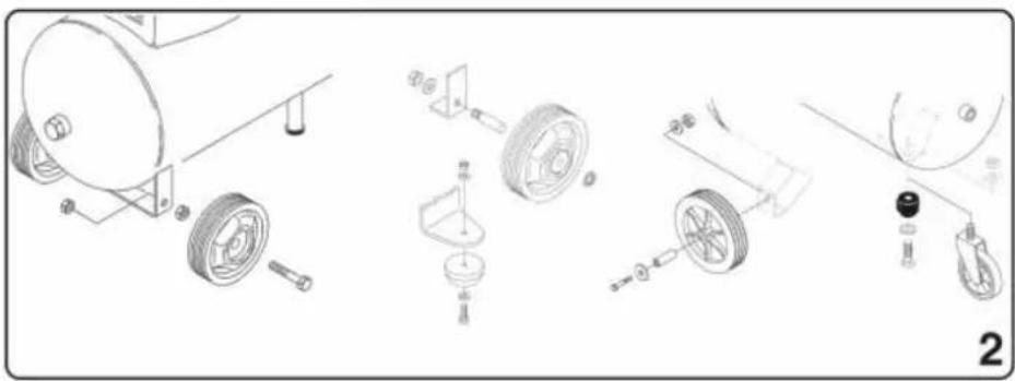
natural_image
Exploded view diagram of a mechanical assembly showing components like wheels, gears, and adjustment parts (no text or labels)
natural_image
Line drawing of a mechanical assembly with vertical bars and hanging components (no text or symbols)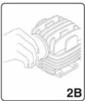
natural_image
Line drawing of a hand inserting a component into a multi-layered electrical component (no text or symbols)
natural_image
Two line drawings of a person standing on ground, one pushing a cart with a bag, the other holding a box (no text or symbols)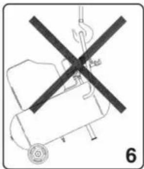
natural_image
Diagram of a mechanical device with a crossed black cross symbol and a numbered label '6' (no text or symbols on the diagram itself)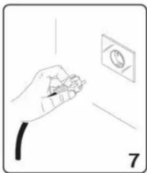
natural_image
Illustration of a hand holding a small object near a wall-mounted electrical outlet (no text or symbols)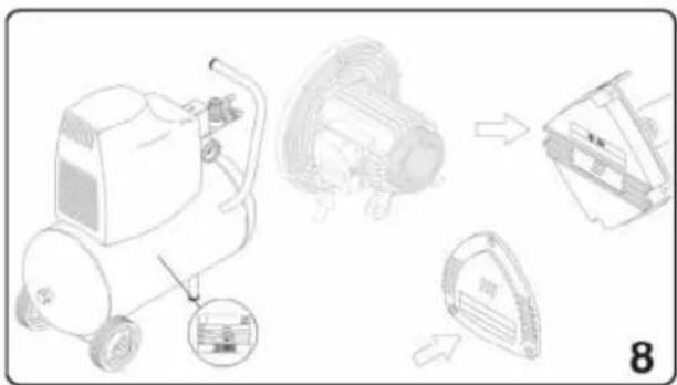
natural_image
Diagram showing a portable air purifier with internal components and a separate view of the same device (no text or symbols present)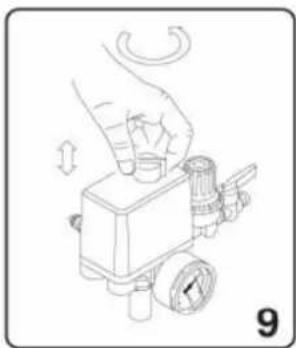
natural_image
Illustration of a hand pressing down on a mechanical pressure regulator device (no text or symbols visible)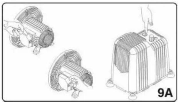
natural_image
Illustration of three mechanical components: a fan with handle, a motor with cooling fan, and a heat exchanger (no text or symbols)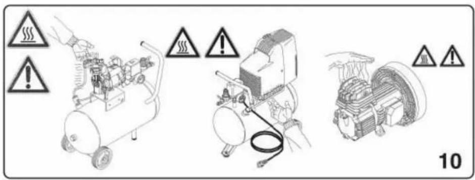
natural_image
Illustration of a portable air compressor, its internal components, and a hand holding a tool (no text or symbols present)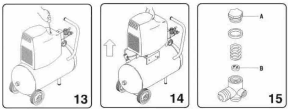
natural_image
Line drawing of a hand using a handheld electronic device (no text or symbols)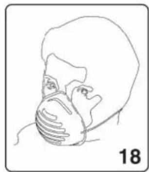
natural_image
Line drawing of a person wearing a face mask and cap, no text or symbols present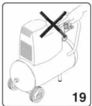
natural_image
Line drawing of a portable air conditioner with a hand holding a black X mark and a number 19 below (no text or symbols on the device itself)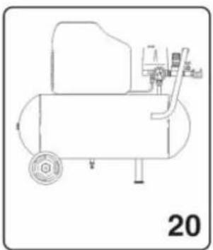
natural_image
Line drawing of a mechanical device with no visible text or symbols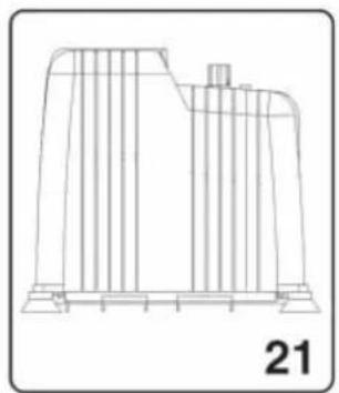
natural_image
Technical line drawing of a mechanical component or structure with vertical divisions and a base plate (no text or symbols)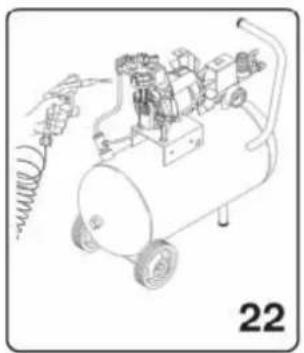
natural_image
Line drawing of an air compressor with wheels and attached components, labeled '22' (no text or symbols on the diagram itself)

natural_image
Illustration of a person standing near a robot with a cross symbol, next to a small dog (no text or symbols present)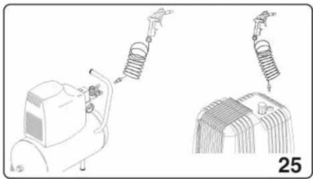
natural_image
Technical line drawing of a mechanical device with spring and coil components, shown in two views (no text or symbols)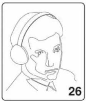
natural_image
Line drawing of a person wearing headphones, labeled with the number 26 (no text or symbols on the figure itself)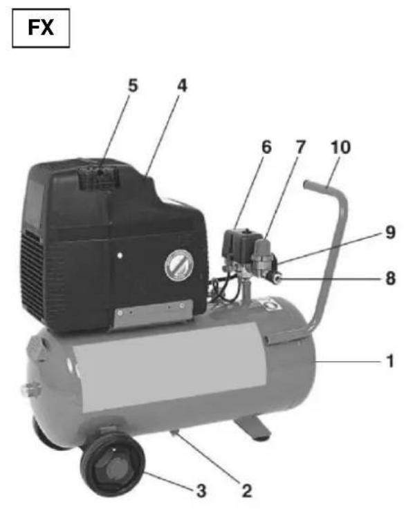
GMS
S ECU FB 210
MOD. FX
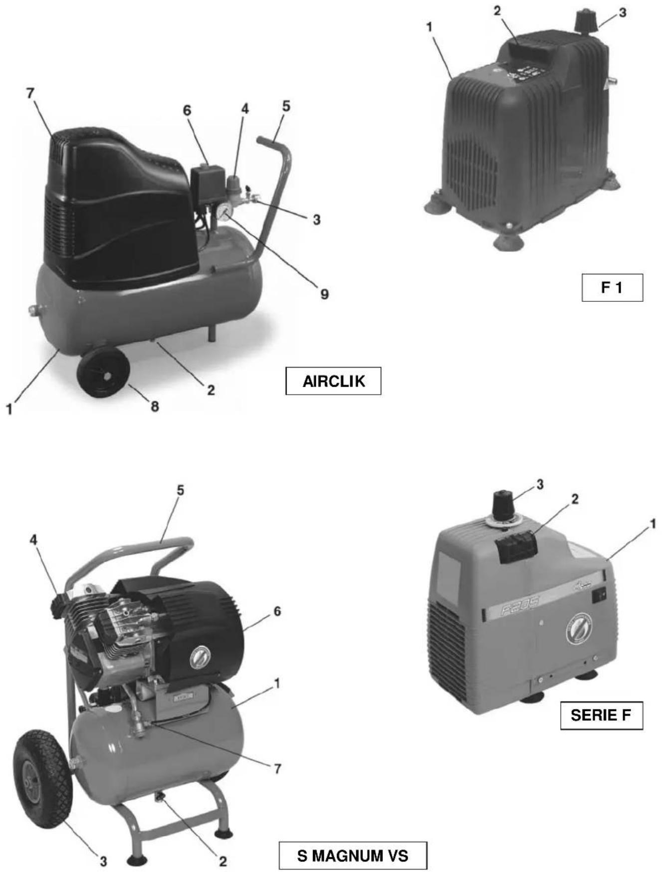
1 SERBATOIO / TANK / RESERVOIR / KESSEL / TANK / BEHOLDER / DEPÓSITO / DEPÓSITO / SÄILIÖ / TANK
2 SCARICO CONDENSA / CONDENSATE DRAIN / EVACUATION CONDENSATION / AUSLASS KONDENSWASSER / AFVOER CONDENSWATER / T∅MNING AF KONDENSVAND / DESAGÜE DEL CONDENSADO / PURGA DA CONDENSAÇÃO / KONDENSSIVEDEN TYHJENNYS / KONDENSVATTNETS AVLOPP
3 RUOTA / WHEEL / ROUE / RAD / WIEL / HJUL / RUEDA / RODA / PYÖRÄ / HJUL
4 CARENATURA DI PROTEZIONE / GUARD / CARENAGE DE PROTECTION / SCHUTZVERKLEIDUNG / BESCHERMINGSSTROOMLIJNKAP / STR∅MLINIEBEKLÆDNING / CARENADURA DE PROTECCIÓN / COBERTURA DE PROTECCÃO / SUOJUS / SKYDDSBEKLÄDNAD
5 FILTRO ARIA / AIR FILTER / FILTRE A AIR / LUFTFILTER / LUCHTFILTER / LUFTFILTER / FILTRO DE AIRE / FILTRO AR / ILMASUODATIN / LUFTFILTER
6 PRESSOSTATO / PRESSURE SWITCH / PRESSOSTAT / DRUCKWÄCHTER / DRUKREGELAAR / PRESSOSTAT / PRESOSTATO / BARÓSTATO / PAINEMITTARI / TYCKMÄTARE
7 RIDUTTORE DI PRESSIONE / PRESSURE REDUCER / REDUCTEUR DE PRESSION / DRUCKMINDERER / DRUKREDUCTIEMACHINE / TRYKBEGRÄNSER / REDUCTOR DE PRESIÓN / REDUTOR DE PRESSÃO / PAINEENVÄHENTÄJÄ / TYCKREDUCERARE
8 USCITA ARIA COMPRESSA / COMPRESSED AIR OUTLET / SORTIE AIR COMPRIME / DRUCKLUFTAUSGANG / UITGANG SAMENGEPERSTE LUCHT / UDGANG FOR TRYKLUFT / SALIDA DEL AIRE COMPRIMIDO / SAIDA AR COMPRIMIDO / PAINEILMAN ULOSOMENO / TRYCKLUFTSUTGÅNG
9 MANOMETRO / PRESSURE GAUCE / MANOMETRE / MANOMETER / MANOMETER / TRYKMÄLER / MANÓMETRO / MANÓMETRO / MANOMETRI / MANOMETER
10 MANICO / HANDLE / POIGNEE / SCHLAUCH / HANDVAT / HANK / MANIJA / ASA / KAHVA / HANDTAG
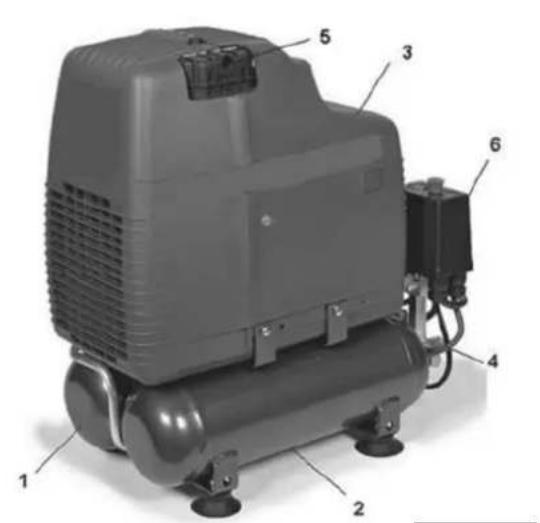
MOD. F 1
1 CARENATURA DI PROTEZIONE / GUARD / CARENAGE DE PROTECTION / SCHUTZVERKLEIDUNG / BESCHERMINGSSTROOMLIJNKAP / STRÖMLINIEBEKLÄEDNING / CARENADURA DE PROTECCIÓN / COBERTURA DE PROTECCÃO / SUOJUS / SKYDDSBEKLÄDNAD
2 FILTRO ARIA / AIR FILTER / FILTRE A AIR / LUFTFILTER / LUCHTFILTER / LUFTFILTER / FILTRO DE AIRE / FILTRO AR / ILMASUODATIN / LUFTFILTER
3 RIDUTTORE DI PRESSIONE / PRESSURE REDUCER / REDUCTEUR DE PRESSION / DRUCKMINDERER / DRUKREDUCTIEMACHINE / TRYKBEGRÄNSER / REDUCTOR DE PRESIÓN / REDUTOR DE PRESSÃO / PAINEENVÄHENTÄJÄ / TYCKREDUCERARE
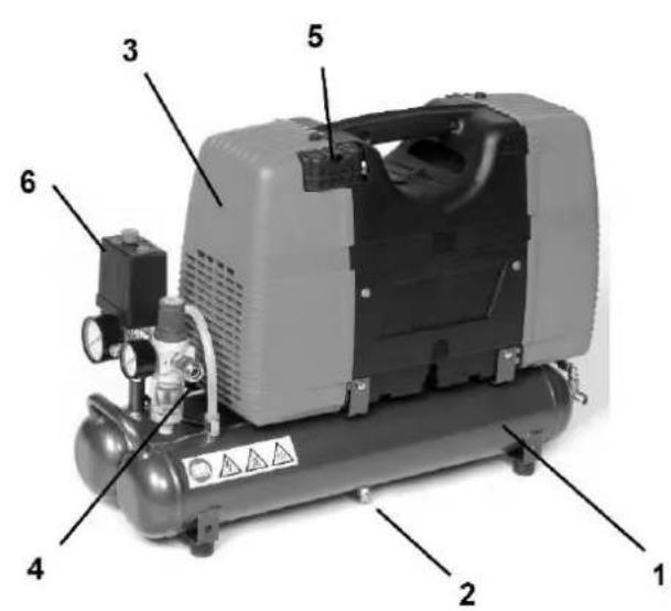
MOD. ECU - S/ECU
1 SERBATOIO / TANK / RESERVOIR / KESSEL / TANK / BEHOLDER / DEPÓSITO / DEPÓSITO / SÄILIÖ / TANK
2 SCARICO CONDENSA / CONDENSATE DRAIN / EVACUATION CONDENSATION / AUSLASS KONDENSWASSER / AFVOER CONDENSWATER / T∅MNING AF KONDENSVAND / DESAGÜE DEL CONDENSADO / PURGA DA CONDENSAÇÃO / KONDENSSIVEDEN TYHJENNYS / KONDENSVATTNETS AVLOPP
3 CARENATURA DI PROTEZIONE / GUARD / CARENAGE DE PROTECTION / SCHUTZVERKLEIDUNG / BESCHERMINGSSTROOMLIJNKAP / STR∅MLINIEBEKLÄEDNING / CARENADURA DE PROTECCIÓN / COBERTURA DE PROTECCÃO / SUOJUS / SKYDDSBEKLÄDNAD
4 VALVOLA DI SICUREZZÄ / SECURITY VALVE / VANNE DE SECURITE / SICHERHEITSVENTIL / VEILIGHEIDSKLEP / SIKKERHEDSVENTIL / VALVULA DE SEGURIDAD / VALVULA DE SEGURANCA / PAINEENALENNENNUSVENTTIILI / SÄKERHETSVENTIL
5 FILTRO ARIA / AIR FILTER / FILTRE A AIR / LUFTFILTER / LUCHTFILTER / LUFTFILTER / FILTRO DE AIRE / FILTRO AR / ILMASUODATIN / LUFTFILTER
6 PRESSOSTATO / PRESSURE SWITCH / PRESSOSTAT / DRUCKWÄCHTER / DRUKREGELAAR / PRESSOSTAT / PRESOSTATO / BARÓSTATO / PAINEMITTARI / TYCKMÄTARE
MOD. F
1 CARENATURA DI PROTEZIONE / GUARD / CARENAGE DE PROTECTION / SCHUTZVERKLEIDUNG / BESCHERMINGSSTROOMLIJNKAP / STRÖMLINIEBEKLÄEDNING / CARENADURA DE PROTECCIÓN / COBERTURA DE PROTECÇÃO / SUOJUS / SKYDDSBEKLÄDNAD
2 FILTRO ARIA / AIR FILTER / FILTRE A AIR / LUFTFILTER / LUCHTFILTER / LUFTFILTER / FILTRO DE AIRE / FILTRO AR / ILMASUODATIN / LUFTFILTER
3 RIDUTTORE DI PRESSIONE / PRESSURE REDUCER / REDUCTEUR DE PRESSION / DRUCKMINDERER / DRUKREDUCTIEMACHINE / TRYKBEGRÄNSER / REDUCTOR DE PRESIÓN / REDUTOR DE PRESSÃO / PAINEENVÄHENTÄJÄ / TYCKREDUCERARE
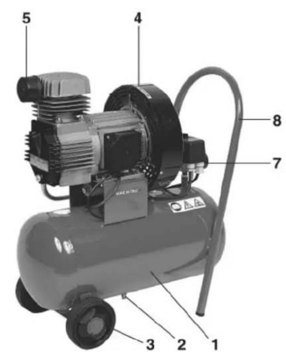
MOD. S.MAGNUM VS
1 SERBATOIO / TANK / RESERVOIR / KESSEL / TANK / BEHOLDER / DEPÓSITO / DEPÓSITO / SÄILIÖ / TANK
2 SCARICO CONDENSA / CONDENSATE DRAIN / EVACUATION CONDENSATION / AUSLASS KONDENSWASSER / AFVOER CONDENSWATER / T∅MNING AF KONDENSVAND / DESAGÜE DEL CONDENSADO / PURGA DA CONDENSAÇÃO / KONDENSSIVEDEN TYHJENNYS / KONDENSVATTNETS AVLOPP
3 RUOTA / WHEEL / ROUE / RAD / WIEL / HJUL / RUEDA / RODA / PYÖRÄ / HJUL
4 FILTRO ARIA / AIR FILTER / FILTRE A AIR / LUFTFILTER / LUCHTFILTER / LUFTFILTER / FILTRO DE AIRE / FILTRO AR / ILMASUODATIN / LUFTFILTER
5 MANICO / HANDLE / POIGNEE / SCHLAUCH / HANDVAT / HANK / MANIJA / ASA / KAHVA / HANDTAG
6 CARENATURA DI PROTEZIONE / GUARD / CARENAGE DE PROTECTION / SCHUTZVERKLEIDUNG / BESCHERMINGSSTROOMLIJNKAP / STRÖMLINIEBEKLÄEDNING / CARENADURA DE PROTECCIÓN / COBERTURA DE PROTECÇÃO / SUOJUS / SKYDDSBEKLÄDNAD
7 VALVOLA DI RITEGNO / CHECK VALVE / VANNE DE RETENNE / RÜCKSCHLAGVENTIL / TEGENHOUDKLEP / KONTRAVENTIL / VÁLVULA DE RETENCIÓN / VÁLVULA DE RETENÇÃO / TAKAISKUVENTTIILI / STOPPVENTIL
MOD. AIRCLIK
1 SERBATOIO / TANK / RESERVOIR / KESSEL / TANK / BEHOLDER / DEPÓSITO / DEPÓSITO / SÄILIÖ / TANK
2 SCARICO CONDENSA / CONDENSATE DRAIN / EVACUATION CONDENSATION / AUSLASS KONDENSWASSER / AFVOER CONDENSWATER / T∅MNING AF KONDENSVAND / DESAGÜE DEL CONDENSADO / PURGA DA CONDENSAÇÃO / KONDENSSIVEDEN TYHJENNYS / KONDENSVATTNETS AVLOPP
3 USCITA ARIA COMPRESSA / COMPRESSED AIR OUTLET / SORTIE AIR COMPRIME / DRUCKLUFTAUSGANG / UITGANG SAMENGEPERSTE LUCHT / UDGANG FOR TRYKLUFT / SALIDA DEL AIRE COMPRIMIDO / SAIDA AR COMPRIMIDO / PAINEILMAN ULOSOMENO / TRYCKLUFTSUTGÅNG
4 RIDUTTORE DI PRESSIONE / PRESSURE REDUCER / REDUCTEUR DE PRESSION / DRUCKMINDERER / DRUKREDUCTIEMACHINE / TRYKBEGRÄNSER / REDUCTOR DE PRESIÓN / REDUTOR DE PRESSÃO / PAINEENVÄHENTÄJÄ / TYCKREDUCERARE
5 MANICO / HANDLE / POIGNEE / SCHLAUCH / HANDVAT / HANK / MANIJA / ASA / KAHVA / HANDTAG
6 PRESSOSTATO / PRESSURE SWITCH / PRESSOSTAT / DRUCKWÄCHTER / DRUKREGELAAR / PRESSOSTAT / PRESOSTATO / BARÓSTATO / PAINEMITTARI / TYCKMÄTARE
7 CARENATURA DI PROTEZIONE / GUARD / CARENAGE DE PROTECTION / SCHUTZVERKLEIDUNG / BESCHERMINGSSTROOMLIJNKAP / STRÖMLINIEBEKLÄEDNING / CARENADURA DE PROTECCIÓN / COBERTURA DE PROTECÇÃO / SUOJUS / SKYDDSBEKLÄDNAD
8 RUOTA / WHEEL / ROUE / RAD / WIEL / HJUL / RUEDA / RODA / PYÖRÄ / HJUL
9 MANOMETRO / PRESSURE GAUCE / MANOMETRE / MANOMETER / MANOMETER / TRYKMÄLER / MANÓMETRO / MANÓMETRO / MANOMETRI / MANOMETER
Read and understand all of the operating instructions, safety precautions and warnings in the Instruction Manual before operating or maintaining this compressor. Most accidents that result from compressor operation and maintenance are caused by the failure to observe basic safety rules or precautions. An accident can often be avoided by recognizing a potentially hazardous situation before it occurs, and by observing appropriate safety procedures. Basic safety precautions are outlined in the "SAFETY" section of this Instruction Manual nad in the sections which contain the operation and maintenance instructions. Hazards that must be avoided to prevent bodily injury or machine damage are identified by WARNINGS on the compressor and in this Instruction Manual. Never use this compressor in a manner that has not been specifically recommended by manufacturer, unless you first confirm that the planned use will be safe for you and others.
MEANINGS OF SIGNAL WORDS WARNING: indicates a potentially hazardous situations which, if ignored, could result in serious personal injury.
CAUTION: indicates a hazardous situations which, if ignored, could result moderate personal injury, or could cause machine damage.
NOTE: emphasizes essential information
SAFETY
IMPORTANT SAFETY INSTRUCTIONS FOR USE OF THE COMPRESSOR.
WARNING:
DEATH OR SERIOUS BODILY INJURY COULD RESULT FROM IMPROPER OR UNSAFE USE OF COMPRESSOR TO AVOID THESE RISKS, FOLLOW THESE BASIC SAFETY INSTRUCTIONS.
READ ALL INSTRUCTIONS
Never place your hands, fingers or other body parts near the compressor's moving parts.
2. NEVER OPERATE WITHOUT ALL GUARDS IN PLACE
Never operate this compressor without all guards or safety features in place and in proper working order. If maintenance or servicing requires the removal of a guard or safety features, be sure to replace the guards or safety feature before resuming operation of the compressor.
3. ALWAYS WEAR EYE PROTECTION
Always wear safety goggles or equivalent eye protection. Compressed air must never be aimed at anyone or any part of the body.
4. PROTECT YOURSELF AGAINST ELECTRIC SHOCK
Prevent body contact with grounded surfaces such as pipes, radiators, ranges and refrigeration enclosures. Never operate the compressor in damp or wet locations.
5. DISCONNECT THE COMPRESSOR
Always disconnect the compressor from the power source and remove the compressed air from the air tank before servicing, inspecting, maintaining, cleaning, replacing or checking any parts.
6. AVOID UNINTENTIONAL STARTING
Do not carry the compressor while it is connected to its power source or when the air tank is filled with compressed air. Be sure the knob of the pressure switch in the "OFF" position before connecting the compressor to its power source.
-
STORE COMPRESSOR PROPERLY When not in use, the compressor should be stored in dry place. Keep out of reach of children. Lock-out the storage area.
-
KEEP WORK AREA CLEAN Cluttered areas invite injurues. Clear all work areas of unnecessary tools, debris, furniture etc...
-
KEEP CHILDREN AWAY Do not let visitors contact compressor extension cord. Alla visitors should be kept safely away from work area.
-
DRESS PROPERLY Do not wear loose clothing or jewerly. They can be caught in moving parts. Wear protective hair covering to contain long hair.
-
DON'T ABUSE CORD Never yank it to disconnect from receptable. Keep cord from heat, oil and sharp edges.
-
MAINTAIN COMPRESSOR WITH CARE Follow instructions for lubricating. Inspect cords periodically and if damaged, have repaired by authorized service facility. Inspect extension cords periodically and replace if damaged.
-
OUTDOOR USE EXTENSION CORDS When compressor in used outdoors, use only extension cords intended for use outdoors and so marked.
-
STAY ALERT Watch what you are doing. Use common sense. Do not operate compressor when you are tired.
Compressor should never be used by you if you are under the influence of alcohol, drugs or medication that makes you drowsy
- CHECK DAMAGED PARTS AND AIR LEAK Before further use of the compressor, a guard or other part is damaged should be carefully checked to determine that it will operate properly and perform its intended function. Check for alignment of moving parts, binding of moving parts, breakage of parts, mounting, air leak, and any other conditions that may affect its operation. A guard or other part that is damaged should be properly repaired or replaced by an authorized service center unless otherwise indicated elsewhere in this Instruction Manual. Have defective pressure switches replaced by authorized service center. Do not use compressor if switch does not turn it on and off.
16. NEVER USE COMPRESSOR FOR APPLICATIONS OTHER THAN THOSE SPECIFIED.
Never use compressor for applications other than those specified in the Instruction Manual. Never use compressed air for breathing or respiration.
- HANDLE COMPRESSOR CORRECTLY Operate the compressor according to the instructions provided herein. Never allow the compressor to be operated by children, individuals unfamiliar with its operation or unauthorized personnel.
18. KEEP ALL SCREWS, BOLTS AND COVERS TIGHTLY IN PLACE
Keep all screws, bolts, and plates tightly mounted. Check their conditions periodically.
-
KEEP MOTOR AIR VENT CLEAN The motor air vent must be kept clean so that air can freely flow at all times. Check for dust build-up frequently.
-
OPERATE COMPRESSOR AT THE RATED VOLTAGE Operate the compressor at voltages specified on their nameplates. If using the compressor at a higher voltage than the rated voltage, it will result in abnormally fast motor revolution and may damage the unit and burn out the motor.
-
NEVER USE A COMPRESSOR WHICH IS DEFECTIVE OR OPERATING ABNORMALLY If the compressor appears to be operating unusually, making strange noises, or otherwise appears defective, stop using it immediately and arrange for repairs by a authorized service center.
-
DO NOT WIPE PLASTIC PARTS WITH SOLVENT Solvents such as gasoline, thinner, benzine, carbon tetrachloride, and alcohol may damage and crack plastic parts. Do not wipe them with such solvents. Wipe plastic parts with a soft cloth lightly dampened with soapy water and dry thoroughly.
23. USE ONLY GENUINE REPLACEMENT PARTS
Replacement parts not original may void your warranty and can lead to malfunction and resulting injuries. Genuine parts are available from your dealer.
24. DO NOT MODIFY THE COMPRESSOR
Do not modify the compressor. Always contact the authorized service center any repairs. Unauthorized modification may not only impair the compressor performance but may also result in accident or injury to repair personnel who do not have the required knowledge and technical expertise to perform the repair operations correctly.
25. TURN OFF THE PRESSURE SWITCH WHEN THE COMPRESSOR IS NOT USED
When the compressor is not used, turn the knob of the pressure switch OFF, disconnect it from the power source and open the drain cock to discharge the compressed air from the air tank.
To reduce the risk of burns, do not touch tubes, heads, cylinder and motors.
27. DO NOT DIRECT AIR STREAM AT BODY
Risk of injury, do not direct air stream at persons or animals.
28. DRAIN TANK
Drain tank daily or after 4 hours of use. Open drain fitting and tilt compressor to empty accumulated water.
29. DO NOT STOP COMPRESSOR BY PULLING OUT THE PLUG
Use the "AUTO/OFF" knob of pressure switch.
30. USE ONLY RECOMMENDED AIR HANDLING PARTS ACCEPTABLE FOR PRESSURE NOT LESS THAN 125 PSI (8.6 BAR)
Risk of bursting. Use only recommended air handling parts acceptable for pressures not less than 125 psi (8.6 bar).
REPLACEMENT PARTS
When servicing use only identical replacement parts. Repairs should be conducted only by authorized service center.
SAFETY
GROUNDING INSTRUCTIONS
This compressor should be grounded while in use to protect the operator from electric shock. The compressor is equipped with a three-conductor cord and three-prong grounding type plug to fit the proper grounding type receptacle. The green (or green and yellow) conductor in the cord is the grounding wire. Never connect the green (or green and yellow) wire to a live terminal. If your units is for use on less than 150 volts, it has a plug that looks like that shown in sketch (A) in figure on the right. An adapter, see sketches (B) and (C), is available for connecting sketch (A) type plugs to two-prong receptacles. The green-colored rigid ear, lug, or the like extending from the adapter must be connected to a permanent ground, such as a properly grounded outlet box. NOTE: the grounding adaptor, sketch (C), is prohibited in Canada by Canadian Electrical Code Part.1. Therefore, the instructions for its use are not applicable in Canada.
EXTENSION CORD
Use only three-extension cords that have three-prong grounding type plugs and three-pole receptables that accept the compressor's plug. Replace or repair damaged cord. Make sure your extension cord is in good condition. When using an extension cord, be sure to use one heavy enough to carry the current your product will draw. An undersized cord will cause a drop in line voltage resulting in loss of power and overheating. Table shows the correct size to use depending on cord lenght and name plate ampere rating. If in doubt, use the next heavier gage. The smaller the gage number, the heavier the cord.
Tab.1 SECTION VALID FOR A MAX LENGTH OF 20 mt single-phase
| HP | kW | 220/230V50 Hz (mm ^2 ) | 110/120V60 Hz (mm ^2 ) |
| 0.75 | 0.65 | 1.5 | |
| 1 | 0.75 | 1.5 | 2.5 |
| 1.5 | 1.1 | 2.5 | |
| 2 | 1.5 | 2.5 | 4 |
| 3 | 2.2 | 4 |
WARNING
Avoid electrical shock hazard. Never use this compressor with a damaged or frayed electrical cord or extension cord. Inspect all electrical cords regularly. Never use in near water or in any environment where electric shock is possible
SAVE THIS INSTRUCTION AND MAKE THEM AVAILABLE OTHER USERS OF THIS TOOL!
OPERATION AND MAINTENANCE NOTE: The information contained in this Instruction Manual is designed to assist you in the safe operation and maintenance of the compressor. Some illustrations in this Instruction Manual may show details or attachments that differ from those on your own compressor.
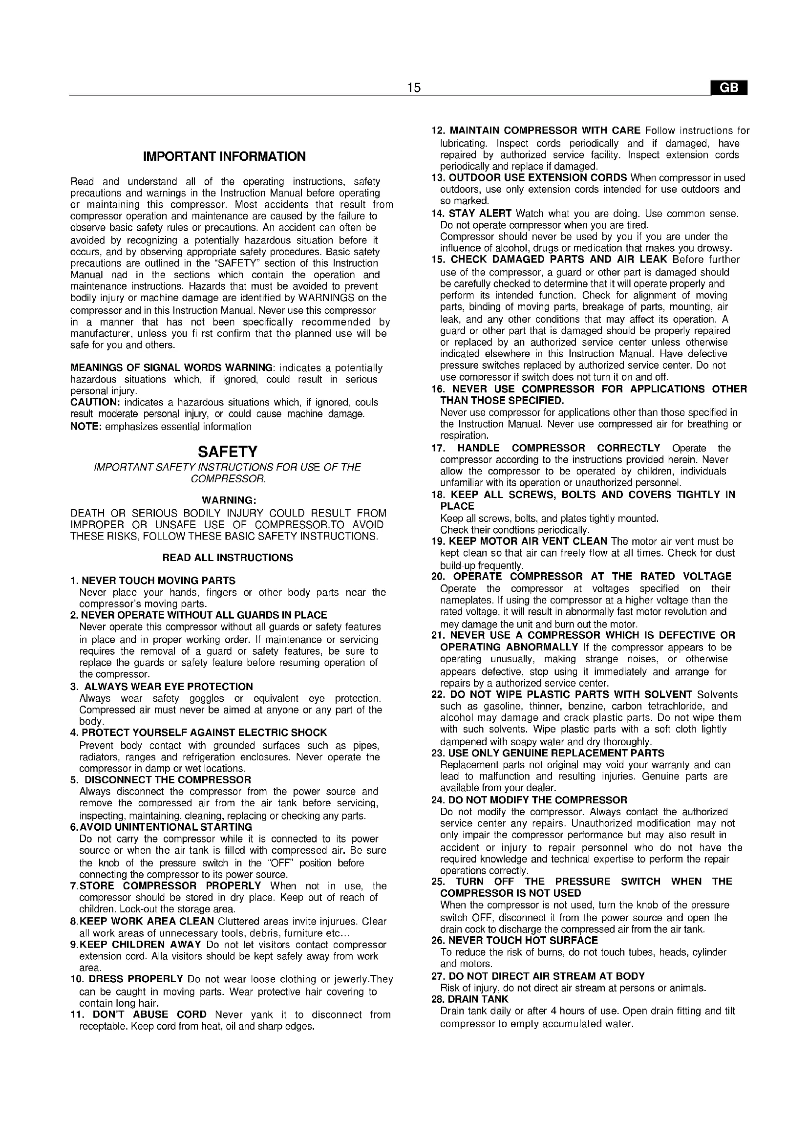
INSTALLATION After having removed the compressor from its packing (fig. 1) and having checked its perfect integrity, making sure that it has not been damaged during transport, proceed as follows.
COMPRESSOR WITH TANK (FIG.20)
Fit the wheels and the rubbers on the tanks where these have not been fitted, following the instructions provided in fig. 2. Also fit the air filter (fig. 2B) in compressors in which this has not been fitted.
COMPRESSOR WITHOUT TANK (FIG.21)
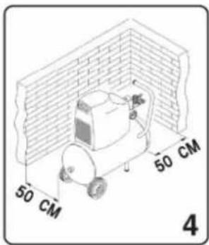
Fit the suction cups underneath the base of the unit as indicated in fi g.2A. Position the compressor on a flat surface or one with an inclination of 10^ at the most (fig. 3), in a well-ventilated area away from atmospheric agents and not in explosive areas. If the surface is sloping and smooth, make sure that the compressor does not move while running, otherwise block the wheels with two wedges. If the surface consists of a shelf or the ledge of a stand, make sure that it may not fall off by securing it appropriately. The compressor must be positioned at least 50 cm away from any walls to ensure its ideal ventilation and effective cooling. (fig. 4).
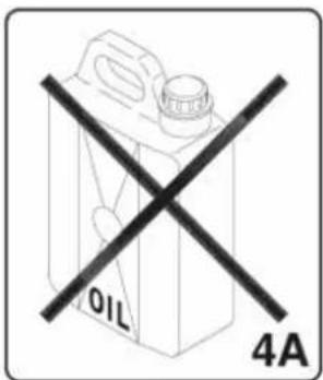
THIS COMPRESSOR RUNS WITHOUT OIL (4A)
OPERATIONAL INSTRUCTIONS
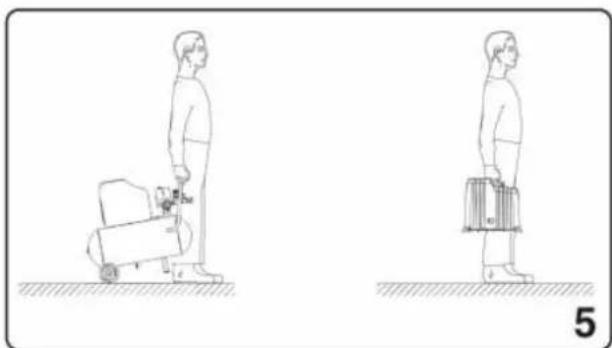
- Transport the compressor in the correct manner without tipping it or lifting it with hooks or ropes. (fig. 5 - 6)
ELECTRICAL CONNECTION The single-phase compressors are supplied complete with an electrical cable and two-pole + earth power plug. The compressor must be connected to a power socket provided with earth connection. (fig. 7)
WARNING:
The earth connection must be achieved according to the industrial safety standards (EN 60204). The plug of the power supply cable must not be used as a switch but must be plugged into a power socket that is controlled by a suitable differential switch (magneto thermal switch).
STARTING
Make sure that the mains voltage corresponds to that indicated on the electrical data nameplate (fig. 8), the admitted tolerance range must remain within ± 5%.
COMPRESSOR WITH TANK (Fig. 20): Turn or press, depending on the type of pressure switch fitted on the equipment, the knob situated in the upper part to «0» (fig. 9). Put the plug in the power socket (fi g. 7) and turn the knob to «1». Attach the rubber hose or the spiral type hose to the appropriate f tting situated near the pressure switch (fig.25). The compressor runs in a completely automatic manner and is controlled by the pressure switch that stops when the pressure inside the tank reaches the maximum pressure and starts it again when the pressure falls back down to the minimum level. The difference in pressure is usually 2 bar (29-6 psi) roughly between the maximum and minimum value. I.e.: the compressor stops when it reaches 8 bar (116 psi) (max. running pressure) and is automatically re-started when the pressure inside the tank falls to 6 bar (87 psi). After having connected the compressor to the electrical power supply line, load to the maximum pressure and check the correct efficiency of the machine.
COMPRESSOR WITHOUT TANK (Fig. 21): Put the plug in the power socket (fig. 7). Press the starting push button situated at the side of the compressor (fig. 9A). This type of compressor is provided with a device that automatically controls the maximum working pressure even if the user is not using compressed air. The compressor automatically releases the excess air from a valve situated on the head. The compressor does not stop automatically. Use the ON/OFF push button to stop the compressor. Attach the rubber hose or the spiral type hose to the appropriate fitting situated at the top of the compressor, near the gear motor (fig. 25).
NOTE: The head/cylinder/delivery hose unit situated beneath the panelling may reach high temperatures therefore be careful when working near these components and do not touch them to avoid getting burned (fig. 10).
WARNING
The electric compressors must be connected to a power socket that is safeguarded by a suitable differential switch (magneto thermal switch).
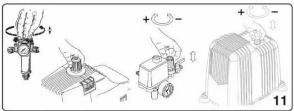
ADJUSTING THE WORKING PRESSURE (fi g. 11) It is not always necessary to use the maximum working pressure, on the contrary the pneumatic tool usually requires less pressure. Adjust the working pressure accurately in compressors provided with pressure regulators. Release the knob of the pressure regulator by pulling it outwards, adjust the pressure to the desired value by turning the knob clockwise to increase it and anti-clockwise to decrease it. Once the ideal pressure has been reached, block the knob by pushing it downwards (fig. 11). In the case of pressure regulators supplied without a gauge, the calibration pressure may be seen on the graduated scale situated on the casing of the actual regulator. In the case of pressure regulators supplied with a gauge, the calibration pressure may be seen on the actual gauge. WARNING: Some pressure regulators do not have "push to lock", therefore simply turn the knob to adjust the pressure.
MAINTENANCE
Before servicing the compressor make sure that:
- the main line ON/OFF switch is on «0»
- the pressure switch or the line switch is on «0».
- there is no pressure in the air tank (only for model with tank).
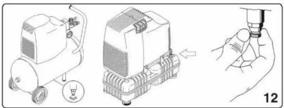
The compressor generates condensate that accumulates in the tank. The condensate must be drained from the tank at least once a week by opening the discharge tap (fig. 12) underneath the tank (only for model with tank). Be careful if there is any compressed air within the cylinder as the water could burst out with some force. Recommended pressure 1 ÷ 2 bar max.
RECOMMENDED MAINTENANCE
In units F with 2 poles, replace the whole connecting rod unit every 700 hours of operation.
In units F and FB with 4 poles, replace the whole connecting rod unit every 1500 hours of operation. In units GMS and VS, replace the sliding blocks and the compression ring every 1500 hours of operation.
LUBRICATING THE BEARINGS
All the bearings are lubricated with grease for life with the exception of the roller casing fitted on the connecting rod side of the GMS and VS units which is to be washed with solvent and re-lubricated with "Kluber Barrierta L 55/2" grease every 1500 hours of operation (white grease). The grease must completely fill the spaces between the rollers; excess lubricant will be expelled during the initial hours of operation.
CLEANING THE FILTER (F-FB-ECU-GMS-VS Series-AIRCLIK-F 1)
It is advisable to dismantle the suction filter every 50 hours of use and to clean the fi ltering element by blowing it with compressed air, or replace it if the element pointed out by the arrow is clogged.
HOW TO PROCEED WHEN TRIVIAL ANOMALIES
ARE ENCOUNTERED Loss of air from the valve underneath the pressure switch (only model with tank)
This inconvenience is due to the imperfect seal of the non-return valve; proceed as follows: (fig. 13). Release all the pressure from the tank. Remove the panelling by unscrewing the four securing screws and lift it. (fig. 13-14) (F 1 and AIRCLIK). Unscrew the hexagonal head of the valve (A)(fig.15). Carefully clean the small rubber disk (B) and also its seat (fig.15). Re-fi t everything accurately.
Loss of air (F-GMS-VS Series)
This may be due to the poor seal of one of the fittings. Check all the fittings by wetting them with soapy water.
The compressor runs but fails to load
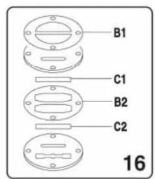
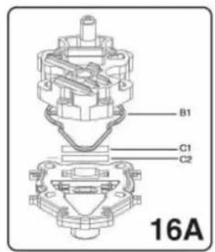
F-GMS-VS series compressors: (fig.16)
- This may be due to a breakage of the valve, or a gasket (B1-B2). Replace the damaged component.
- This may be due to a breakage of the valves (C1-C2), or a
gasket
(B1-B2). Replace the damaged component (fig.16B). AirClik-F 1 series (fig. 16A):
- This may be due to the breakage of the valves (C1 - C2) or of the gasket (B1). Replace the damaged part (fig. 16A).
The compressor fails to start
If the compressor has difficulty in starting, make sure that: -the mains voltage corresponds to that indicated on the data nameplate (fi g. 8)
- electrical extension cables with unsuitable cross-section or length are not used.
- the room in which the compressor is running is not too cold (below 0°C)
- the electric line is efficient (plug connected correctly, magneto thermal switch, fuses not blown)
The compressor fails to stop (only with tank)
if the compressor fails to stop when the maximum pressure is reached, the tank safety valve will trip. Contact the nearest authorised service centre for the repairs.
WARNING
- Do not unscrew any connections with the tank when under pressure for any reason whatsoever. Always make sure that the tank is depressurised beforehand.
- Do not drill, weld or intentionally deform the compressed air tank.
- Do not carry out any operations on the compressor before it has been unplugged from the power socket.
- The room temperature for its correct efficiency is: 0°C +25°C (MAX 45°C).
- Do not direct jets of water or flammable liquids over the compressor.
- Do not place flammable objects near the compressor.
- When stopped temporarily during its use, turn the pressure switch or the ON/OFF switch to position «0» (OFF) (turned-off).
- Never direct the jet of air towards people or animals (fig. 24).
- Do not transport the compressor when the tank is pressurised.
- Be aware that some components of the compressor such as the head and delivery hoses may reach high temperatures, therefore do not touch the to avoid getting burned (fig. 10).
- Transport the compressor by lifting or pulling it with the appropriate grips or handles (fig. 5 - 6).
- Children and animals must be kept away from the area in which the machine is running. If the compressor is used for painting: a) Do not work in closed areas or near free flames b) Make sure that the area in which you are working has a good change of air c) Protect nose and mouth using an appropriate mask (fig. 18).
- Do not use the compressor if the electric cable or the plug is damaged.
- Contact the nearest authorised service centre for the replacement with an original component.
- If it is placed on a shelf or a surface that is raised off the ground, it must be secured appropriately to prevent it from tipping off when running.
- Do not insert objects or your hands inside the safety grating to avoid physical damage and also damage to the compressor (fig. 19).
- Do not use the compressor to threaten people or animals to avoid serious injuries.
- Always unplug the compressor from the power socket when you have finished using it.
ELECTRIC COMPRESSOR MODEL (GMS-VS-AIRCLIK-F 1-F)
Maximum running pressure: 8.5 bar
Maximum working pressure: 8 bar
ELECTRIC COMPRESSOR MODEL (FB 210)
Maximum running pressure: 10.5 bar
Maximum working pressure: 10 bar
NOTE:
The compressor tanks have been manufactured in compliance with the 2009/105/EC Directive for the European market. The compressors have been manufactured in compliance with the 2006/42/EC Directive for the European market.
The measured sound pressure level measured in a free range at a distance of 1 m: ±3dB(A) at the maximum working pressure. (table 3)
SERIE F
| HP/kW | RPM | Db(A) | |
| 1/0.75 | 1450-1750 | 65 | |
| 1.5/1.1 | 2850 | 77 | |
| 1.5/1.1 | 3450 | 80 | |
| 2/1.5 | 2850 | 78 | |
| SERIE FB | |||
| HP/kW | RPM | Db(A) | |
| 2/1.5 | 1450 | 67 | |
| SERIE GSM | |||
| HP/kW | RPM | Db(A) | |
| 0.75/0.55 | 1450/1750 | 77 | |
| 1.5/1.1 | 1450/1750 | 77 | |
| 1.5/1.1 | 2850 | 78 | |
| SERIE VS | |||
| HP/kW | RPM | Db(A) | |
| 2/1.5 | 1450 | 77 | |
| 2/1.5 | 1750 | 80 | |
| 3/2.2 | 2850 | 82 | |
The value of the sound level may increase from 1 to 10 dB(A) depending on the room in which the compressor is installed.
HINTS FOR EFFICIENT OPERATION AIRCLIK / F 1
THE F1 & AIRCLICK COMPRESSORS HAVE BEEN DESIGNED FOR INTERMITTENT USE, THESE MODELS SHOULD ONLY BE USED FOR APPLICATIONS WHERE USAGE WILL NOT EXCEED 25% OF DUTY OVER THE COURSE OF ONE HOUR.
PNEUMATIC CONNECTIONS
Make sure you always use pneumatic tubes for compressed air with maximum pressure characteristics that are adequate for the compressor. Do not attempt to repair tubes if faulty.
WE RESERVE THE RIGHT TO MAKE ANY MODIFICATIONS WITHOUT PRIOR NOTICE WHENEVER NECESSARY
INFORMATIONS IMPORTANTES
- AFBRYD KOMPRESSOREN FRA ELNETTET
KOMPRESSORER MED BEHOLDER (fi g.20)
KOMPRESSORER UDEN BEHOLDER (FIG.21)
HYÖDYLLISIÄ NEUVOJIA HYVÄLLE TOIMINNALLE AIRCLIK / F 1
MALLEJA F 1 JA AIRCLIK EI OLE TARKOITETTU JATKUVAAN KÄYTTÖÖN. KÄYTÄ NIITÄ KATKONAISESTI. NÄMÄ MALLIT ON TARKOITETTU AINOASTAAN HARRASTE-LIJAKÄYTTÖÖN EMME SUOSITTELE 25% YLITTÄVÄÄ TOIMINTAA YHDEN TYÖTUNNIN AIKANA.
PNEUMAATTISET KYTKENNÄT
OBS: understryker viktig information.
SÄKERHET
VIKTIGA INSTRUKTIONER FÖR ETT SÄKERT BRUK AV KOMPRESSORN.
WARNING:
EN FELAKTIG ANVÄNDNING OCH ETT DÅLIGT UNDERHÅLL AV DENNA KOMPRESSOR KAN FÖRORSAKA FYSISKA KROPPSSKADOR PÅ ANVÄNDAREN. FÖR ATT UNDVIKA DESSA RISKER, BER VI DIG ATT LÅSA FÖLJANDE INSTRUKTIONER NOGA.
LÄS ALLA INSTRUKTIONER
- RÖR INTE DE RÖRLIGA DELARNA
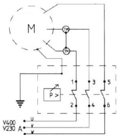
1-2-3-4-5-6 = WIRE CONNECTION TERMINALS
C - CONDENSER
M - MOTOR
AU = AUXILIARY WINDING
AM = STARTING WINDING
FR
A = Alimentation
P = Pressostat
TRIFASE V220/60/3
V230/50/3
THREE/PHASE V400/50/3
V380/50/3
V380/60/3
IT
GARANZIA:
The electro-compressors are warranted for 12 months as from duly documented date of sale. This warranty is granted only to clients who are up to date with their payments. The compressor is warranted for normal operational duty of 8 hours per day in a suitable place. The compressor must be expertly installed. In the event of trouble caused by manufacturing faults occurring during the warranty period, the manufacturer shall replace free of charge parts recognised as faulty. Travelling and labour costs shall be, in any event, charged to the client. The following are excluded from the warranty: damage caused by poor maintenance, negligence and use under unsuitable conditions. The guarantee does not cover motors and all other electrical parts as well as parts subject to wear.