CC67I28SB - Basket BEST - Free user manual and instructions
Find the device manual for free CC67I28SB BEST in PDF.
Document temporarily unavailable
The manual is currently being transferred to our new server. It will be accessible again in a few hours. Thank you for your patience.
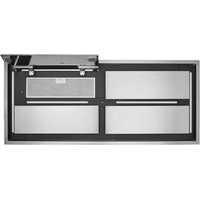
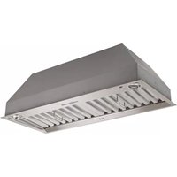
| Product type | Built-in range hood |
| Brand | BEST |
| Model | CC67I28SB |
| Configuration | Dual blower |
| Maximum airflow | 1000 CFM |
| Lighting | 2 LED modules with two intensity levels |
| Controls | Electronic buttons: delayed shut-off, 4 speeds, Heat Sentry, filter maintenance reminder |
| Speeds | 4 (1 for low, 4 for high) |
| Delayed shut-off | Yes (5 minutes) |
| Heat Sentry | Yes (thermal protection, automatic switch to speed 3) |
| Exhaust duct | 10-inch round (diameter) |
| Installation | Built-in cabinet (2 installers recommended) |
| Minimum distance above cooktop | 24 in (electric) / 30 in (gas) |
| Power supply | 120 V, 60 Hz, 3-conductor cable (black, white, green/ground) |
| Weight | 45 lb (20.4 kg) |
| Filters | Metal, dishwasher-safe |
| Material | Stainless steel |
| Included accessories | 10-inch adapter/damper, in-line damper, wire nuts, connection caps, screws |
| Cabinet trim options | ALCC630SB (30 in), ALCC636SB (36 in), ALCC642SB (42 in) |
| Warranty | 5-year limited |
| Use | Indoor, residential only |
Frequently Asked Questions - CC67I28SB BEST
User questions about CC67I28SB BEST
0 question about this device. Answer the ones you know or ask your own.
Ask a new question about this device
Download the instructions for your Basket in PDF format for free! Find your manual CC67I28SB - BEST and take your electronic device back in hand. On this page are published all the documents necessary for the use of your device. CC67I28SB by BEST.