
CC34IQT63SB - Range hood BEST - Free user manual and instructions
Find the device manual for free CC34IQT63SB BEST in PDF.

| Brand | BEST |
| Model | CC34IQT63SB |
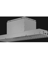
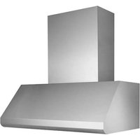
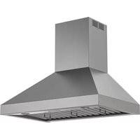
| Product type | Built-in hood |
| Weight | 55 kg (121 lb) |
| Power supply | 120 VAC, 60 Hz |
| Duct diameter | 25.4 cm (10 in) |
| Minimum installation height | 122 cm (48 in) above cooking surface |
| Maximum installation height | 183 cm (72 in) |
| Number of motor speeds | 4 |
| Lighting | LED with 3 levels (low/medium/high) |
| Grease filters | 4 dishwasher-safe metal filters |
| Charcoal filters (optional) | Compatible with recirculation version (kit ANKCC3463) |
| Remote control | Yes, factory-paired |
| Delayed shut-off function | 10 minutes |
| Filter alarm | After 30 hours of operation |
| Calibration technology | IQ MC Guaranteed Performance |
| Warranty | 5-year limited (parts and labor) |
| Material | Stainless steel |
| Use | Indoor only |
| Installation type | Non-IC (insulation at least 76 mm) |
Frequently Asked Questions - CC34IQT63SB BEST
User questions about CC34IQT63SB BEST
0 question about this device. Answer the ones you know or ask your own.
Ask a new question about this device
Download the instructions for your Range hood in PDF format for free! Find your manual CC34IQT63SB - BEST and take your electronic device back in hand. On this page are published all the documents necessary for the use of your device. CC34IQT63SB by BEST.
USER MANUAL CC34IQT63SB BEST
natural_image
Isometric line drawing of a rectangular frame with internal compartments and arrows indicating direction (no text or symbols)Model CC34IQ63SB CC34IQT63SB
ENGLISH....3
FRANÇAIS......23
ESPAÑOL......45
In USA - BEST Hartford, Wisconsin
In CANADA - BEST Drummondville, QC, Canada
REGISTER YOUR PRODUCT ONLINE AT : www.BestRangeHoods.com/register
For additional Information visit www.BestRangeHoods.com
READ AND SAVE THESE INSTRUCTIONS

- Use this unit only in the manner intended by the manufacturer. If you have questions, contact the manufacturer at the address or telephone number listed in the warranty.
- Before servicing or cleaning unit, switch power off at service panel and lock service panel to prevent power from being switched on accidentally. When the service disconnecting means cannot be locked, securely fasten a prominent warning device, such as a tag, to the service panel.
- Installation work and electrical wiring must be done by a qualified person(s) in accordance with all applicable codes and standards, including fire-rated construction codes and standards.
- Sufficient air is needed for proper combustion and exhausting of gases through the flue (chimney) of fuel burning equipment to prevent backdrafting. Follow the heating equipment manufacturer's guidelines and safety standards such as those published by the National Fire Protection Association (NFPA), and the American Society for Heating, Refrigeration and Air Conditioning Engineers (ASHRAE), and the local code authorities.
- When cutting or drilling into wall or ceiling, do not damage electrical wiring and other hidden utilities.
- Ducted fans must always be vented to the outdoors.
- Do not use this unit with any separate solid-state speed control device.
- To reduce the risk of fire, use only steel ductwork.
- This unit must be grounded.
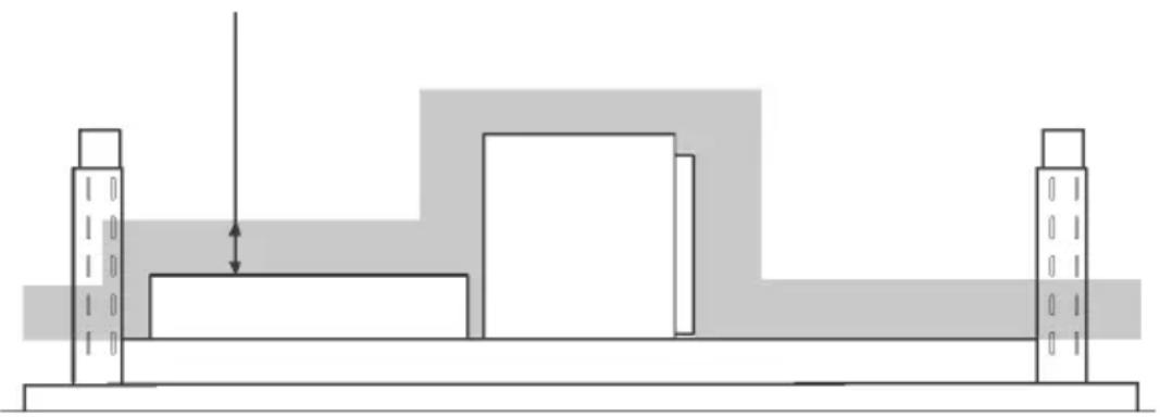
- Type Non-IC Installation: Thermal insulation shall not cover top of range hood housing and must be spaced 3-inches (76mm) from all sides. (Fig. 1)
3-INCH MINIMUM.
NO INSULATION WITHIN THIS SHADED
AREA OF COMPONENTS.
natural_image
Pure architectural or mechanical diagram showing two vertical posts and a central block with an arrow, no text or symbols present.FIG. 1
TO REDUCE THE RISK OF A RANGE TOP GREASE FIRE:
A. Never leave surface units unattended at high settings. Boilovers cause smoking and greasy spillovers that may ignite. Heat oils slowly on low or medium settings.
B. Always turn hood ON when cooking at high heat or when fl ambeing food (i.e. Crepes Suzette, Cherries Jubilee, Peppercorn Beef Flambe').
C. Clean ventilating fans frequently. Grease should not be allowed to accumulate on fan or filter.
D. Use proper pan size. Always use cookware appropriate for the size of the surface element.
TO REDUCE THE RISK OF INJURY TO PERSONS IN THE EVENT OF A RANGE TOP GREASE FIRE, OBSERVE THE FOLLOWING:\*
- SMOTHER FLAMES with a close-fitting lid, cookie sheet, or metal tray, then turn off the burner. BE CAREFUL TO PREVENT BURNS. If the flames do not go out immediately, EVACUATE AND CALL THE FIRE DEPARTMENT.
- NEVER PICK UP A FLAMING PAN - You may be burned.
- DO NOT USE WATER, including wet dishcloths or towels - violent steam explosion will result.
- Use an extinguisher ONLY if:
A. You know you have a Class ABC extinguisher and you already know how to operate it.
B. The fire is small and contained in the area where it started.
C. The fire department is being called.
D. You can fight the fire with your back to an exit.
* Based on "Kitchen Fire Safety Tips" published by NFPA.

CAUTION
- For indoor use only.
- To reduce risk of fire and to properly exhaust air, be sure to duct air outside. Do not vent exhaust air into spaces within walls or ceilings or into attics, crawl spaces, or garages.
- Take care when using cleaning agents or detergents.
- Avoid using food products that produce flames under the Range Hood.
- For general ventilating use only. Do not use to exhaust hazardous or explosive materials and vapors.
- To avoid motor bearing damage and noisy and/or unbalanced impellers, keep drywall spray, construction dust, etc. off power unit.
- Your hood motor has a thermal overload which will automatically shut off the motor if it becomes overheated. The motor will restart when it cools down. If the motor continues to shut off and restart, have the hood serviced.
- For best capture of cooking impurities, the bottom of the hood should be a minimum of 48" and a maximum of 72" above the cooking surface. See "Install Mounting Bracket" section for mounting restrictions.
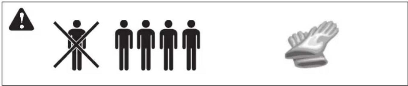
- Multiple installers are recommended because of the large size and weight of this hood.
-
Please read specification label on product for further information and requirements.
-
This power pack is equipped with a RF receiver (optional remote control sold separately). Changes or modifications not expressly approved by the party responsible for compliance could void the user's authority to operate this product. The remote control has been tested and found to comply with the limits for a Class B digital device, pursuant to part 15 of the FCC Rules and the Canadian ICES-003. These limits are designed to provide reasonable protection against harmful interference in a residential installation. The remote control generates, uses and can radiate radio frequency energy and, if not installed and used in accordance with the instructions, may cause harmful interference to radio communications. However, there is no guarantee that interference will not occur in a particular installation. If this equipment does cause harmful interference to radio or television reception, which can be determined by turning the equipment off and on, the user is encouraged to try to correct the interference by one or more of the following measures:
-
Reorient or relocate the receiving antenna.
- Increase the separation between the equipment and receiver.
- Connect the equipment into an outlet on a circuit different from that to which the receiver is connected.
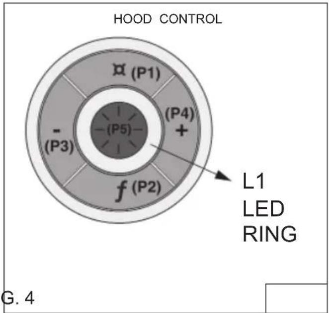
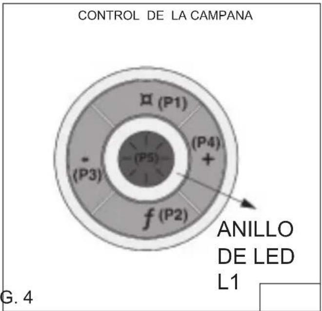
Controls (Fig.2)
The hood is operated using the (5) push buttons located on the hood and the remote control. LED colors are displayed on hood control only.
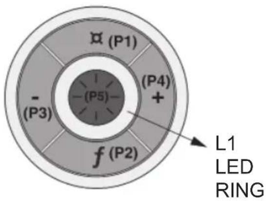
P1: Activate/deactivate delay-off (10 minute)
P2: Filter change indication timer reset
P3: Decreases fan motor speed until turned off (4>3>2>1>OFF)
P4: Turns fan motor on and increased speed (ON>1>2>3>4)
P5: Lights off /low/medium/high
L1: LED Indicator Ring Signalling crown:
- Hood in standby: lights up green. 30 seconds after the last key has been pressed the crown turns off - Motor on: L1 lights up blue flashing. The flashing frequency is proportional to the speed setting.
- 10' TIMER function : L1 lights up and fl ashes blue.
- Filter alarm active: L1 lights up red
FIG. 2
(P1) Delay- Off Switch
- Your hood includes a 10 minute blower delay off switch. Press this switch once to activate the timer and the LED Ring (L1) fl ashes blue. The blower will continue to operate for 10 minutes. After 10 minutes, the blower turns off automatically.
- To cancel the 10-minute delay, press the delay switch once again.
(P2) Filter Alarm Switch
• After 30 hours of blower operation, the filter alarm is activated and the LED ring (L1) turns red/flashes. It indicates that the grease filters need to be cleaned.
- After cleaning the grease filters, reset the hour counter by pressing the Filter Alarm/Timer Reset button (P2) during display of the alarm.
(P3) Blower Speed Decrease and Off Switch
- Press to decrease blower speed, high to low. The LED ring (L1) fl ashes blue at a speed proportionate to the blower setting (i.e.: four fl ashes is high speed, one fl ash is low speed, etc.)
- Continue pressing this switch to turn the blower off.
(P4) Blower Speed Increase and On Switch
- Press this switch to turn the blower on to low speed.
- Press again to increase blower speed, low to high. The LED ring (L1) flashes blue at a speed proportionate to the blower setting (i.e.: four flashes is high speed, one flash is low speed, etc.)
(P5) Light Switch
Lights off /low/medium/high.
The remote control is linked to the hood at the factory. If, for some reason, the link is lost - follow the directions below:
To Link Remote Control to Hood
- Turn off hood motor and hood lights.
- Press ☐ and 🚗 buttons on the remote simultaneously for 5 seconds, until the remote control Indicator Light turns on (Fig.3). Release ☐ and 🚗 buttons. Press and release 🔔 button to confirm the linking. At this point the remote control Indicator Light starts flashing to confirm the link is active.
- Within 3 seconds - press f (P2) on the hood control (Fig. 4). The LED ring will light up for approximately 10 seconds to confirm that the linking process was successful.
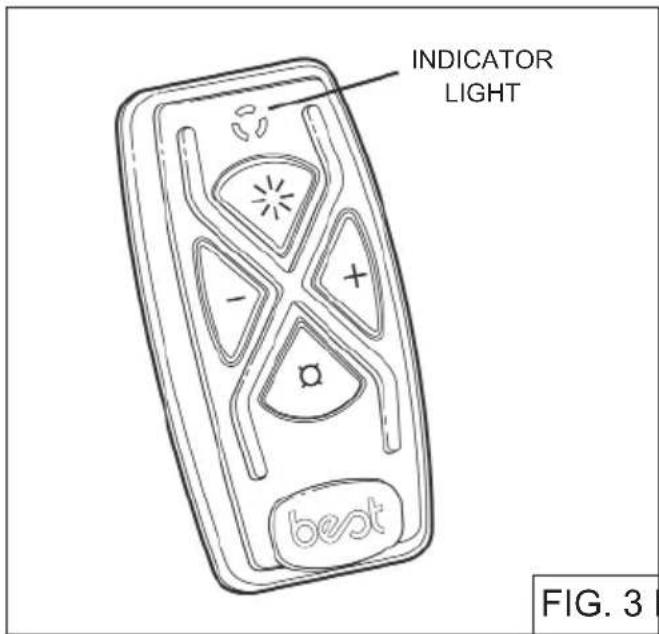
FIG. 3 FIG. 4
Remote Control Functions (Fig.3)

Delay - Off

Blower Speed Decrease and Off

Blower Speed Increase and On

Light
See "Controls" section on previous page for more information on each function.
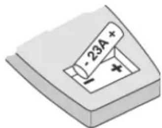
Press (Delay) and (Light) together to Reset Filter Alarm. IMPORTANT: holding (Delay) for more than 3 seconds will cause the link between the remote and hood to be lost. CAUTION RISK OF EXPLOSION IF BATTERY IS REPLACED BY AN INCORRECT TYPE. DISPOSE OF USED BATTERY TO THE INSTRUCTION.
Battery disposal
When the batteries need to be replaced, dispose of them only and exclusively in the numerous readily available special waste bins, especially in shops selling electronic consumer goods. Observance of the regulations on differentiated waste collection, in particular, proper disposal of used batteries, contributes to preventing possible negative effects on the environment and health.
Proper maintenance of the Range Hood will assure proper performance of the unit.
Motor
The motor is permanently lubricated and never needs oiling. If the motor bearings make excessive or unusual noise, replace the motor with the exact service motor. The impeller should also be replaced.
Grease Filter
The grease fi Iters should be cleaned frequently. Use a warm detergent solution. Grease fi Iter are dishwasher safe.
Clean all-metal filters in the dishwasher using a non-phosphate detergent. Discoloration of the filter may occur if using phosphate detergents, or as a result of local water conditions - but this will not affect filter performance. This discoloration is not covered by the warranty. See "INSTALL FILTERS" section for removal and installation instructions.
Stainless Steel Cleaning
DO:
- Regularly wash with clean cloth or rag soaked with warm water and mild soap or liquid dish detergent.
• Always clean in the direction of original polish lines.
• Always rinse well with clear water (2 or 3 times) after cleaning. Wipe dry completely.
DON'T:
- Use any steel or stainless steel wool or any other scrapers to remove stubborn dirt.
- Use any harsh or abrasive cleansers.
- Allow dirt to accumulate.
- Let plaster dust or any other construction residues reach the hood. During construction/renovation, cover the range hood to make sure no dust sticks to the stainless steel surface.
Avoid: When choosing a detergent
- Any cleaners that contain bleach will attack stainless steel
- Any products containing: chloride, fluoride, iodide, bromide will deteriorate surfaces rapidly.
- Any combustible products used for cleaning such as acetone, alcohol, ether, benzol, etc., are highly explosive and should never be used close to a range.
PREPARE THE HOOD
Unpack hood and check contents.
You should receive:
1 - Range Hood
1 - Remote Control
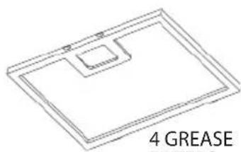
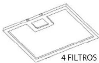
4 - Grease Filters
6 - Lag Bolts, 6 x 60 mm for wood
6 - Washer
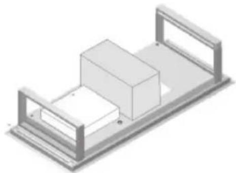
natural_image
Isometric view of a mechanical assembly with two rectangular components mounted on a base plate (no text or symbols visible)RANGE HOOD BODY WITH DAMPER

6 WASHER
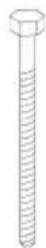
6 LAG BOLTS
(6 x 60 mm)
for wood
natural_image
Isometric line drawing of a rectangular frame with a small square cutout and label '4 GREASE' (no other text or symbols)4 GREASE FILTERS
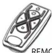
REMOTE CONTROL
FIG. 5
The installer is responsible for selecting fasteners that are suitable for the building construction.
INSTALL THE DUCTWORK
WARNING: To reduce the risk of fire, use only metal ductwork.
- Decide where the ductwork will run between the hood and the outside. Fig. 6.
- A straight, short duct run will allow the hood to perform most efficiently. For optimal performance, it is recommended to have 18 - 24" of straight duct before using an elbow.
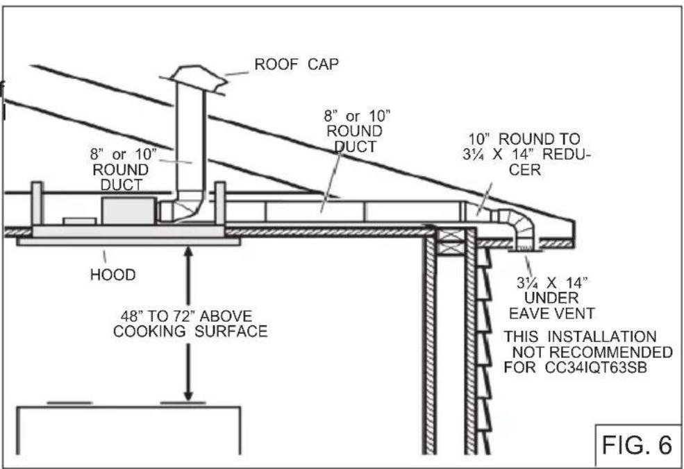
- Long duct runs, elbows, and transitions will reduce the performance of the hood. Use as few of them as possible. Larger ducting may be required for best performance with longer duct runs.
- Install a roof cap, wall cap, or under-eave vent. Connect round metal ductwork to cap/vent and work back towards hood location. Use duct tape to seal the joints between ductwork sections.
- The blower on model CC34IQ63SB can be rotated according to the air outlet location. See Fig. 7 for air outlet dimensions.
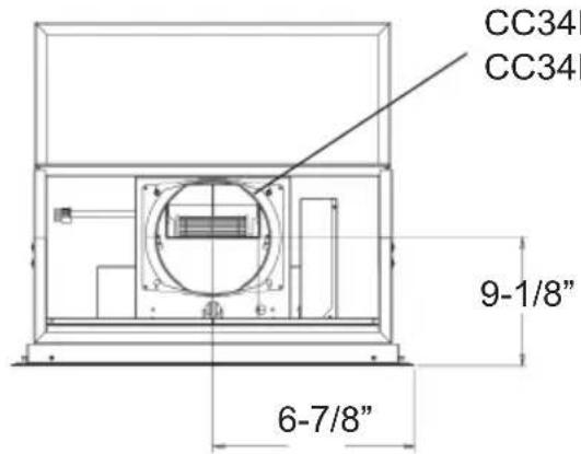
FIG. 7
For Recirculation Mode, purchase KIT ANKCC3463 separately (Optional for CC34IQ63SB only). Fig.8
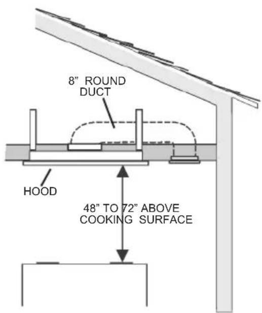
FIG. 8
PREPARE THE CEILING OPENING
The hood should always be centered over the cooktop. Make sure there is adequate space in the ceiling structure to install the hood and ductwork. The hood should be mounted 48" to 72" above the cook top for best removal of cooking impurities. Fig 6.
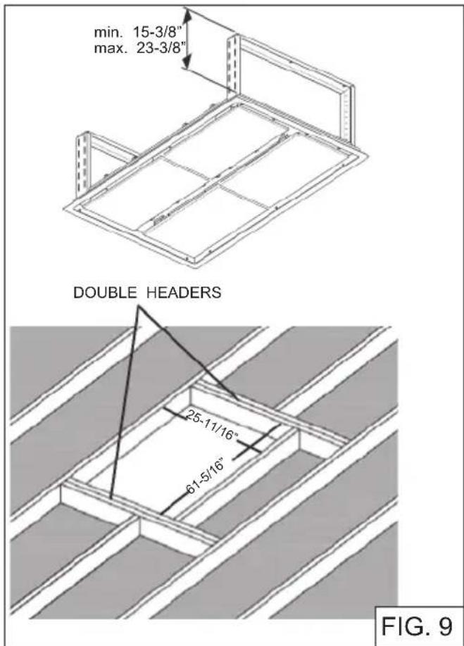
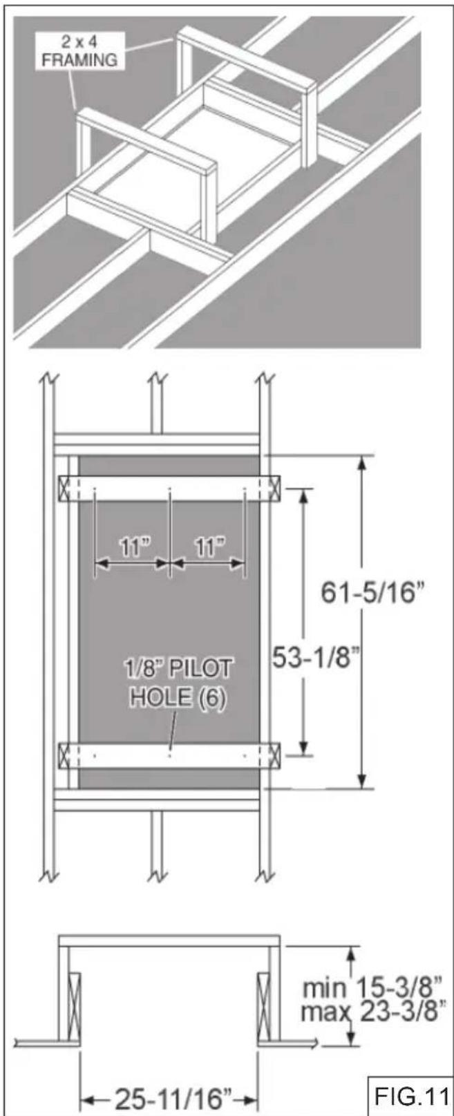
Use joist size lumber to frame in around the range hood opening. Fig 9.
The ceiling structure must be able to support the weight of the hood.
CC34IQ63SB Model: 105 pounds weight.
CC34IQT63SB Model: 121 pounds weight.
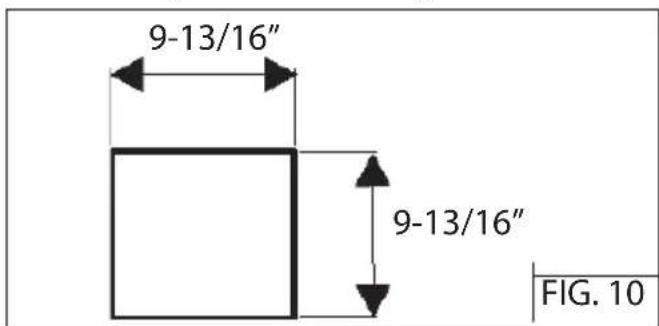
For Non-Ducted version:
Make a cut-out in the ceiling for the air return vent. See Fig. 10 below and Fig. 24.
PREPARE THE HOOD SUPPORT
- Construct a wood framing system as shown in Fig. 11.
- The structure must be capable of supporting its own weight, plus the weight of the hood.
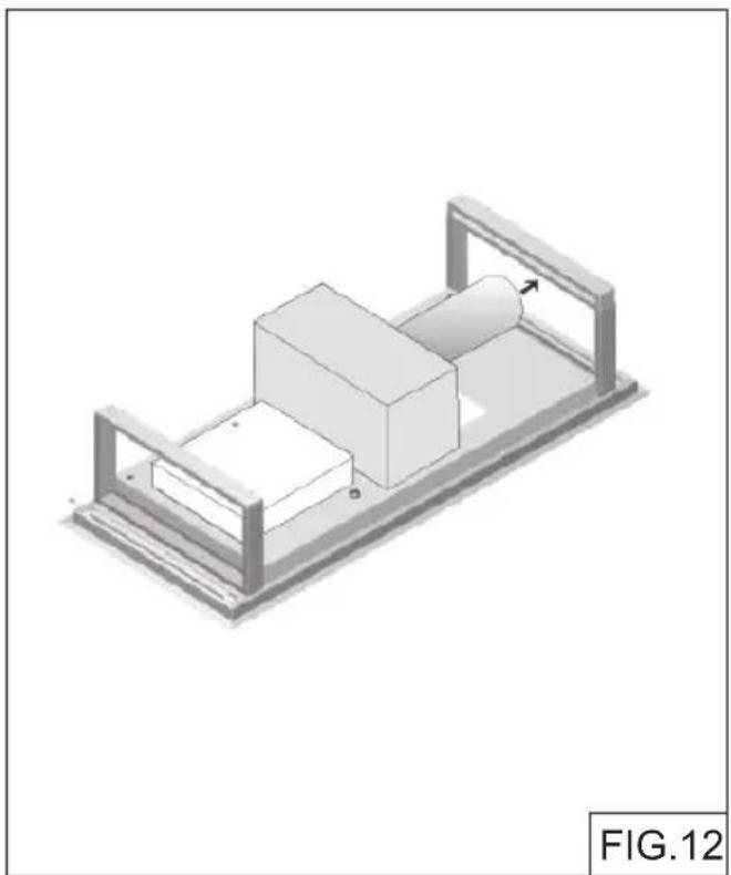
INSTALL THE HOOD

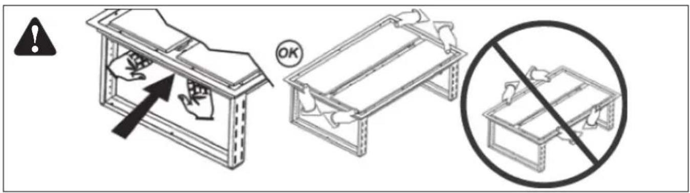
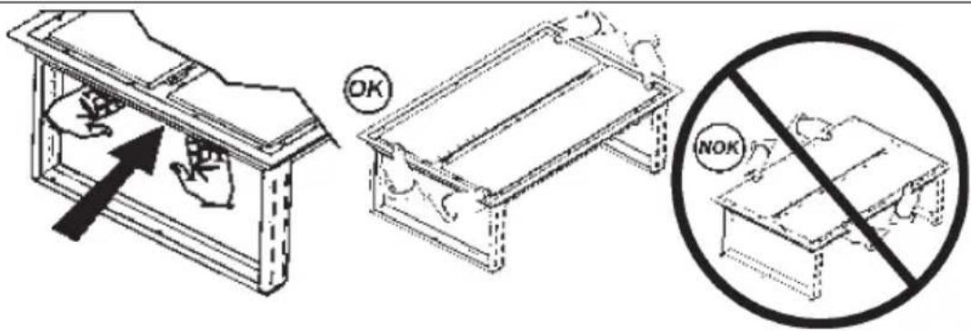
CAUTION: Multiple installers are recommended because of the large size and weight of this range hood.
- Hood is shipped in the horizontal duct discharge position and is ready to be installed (Fig.12).
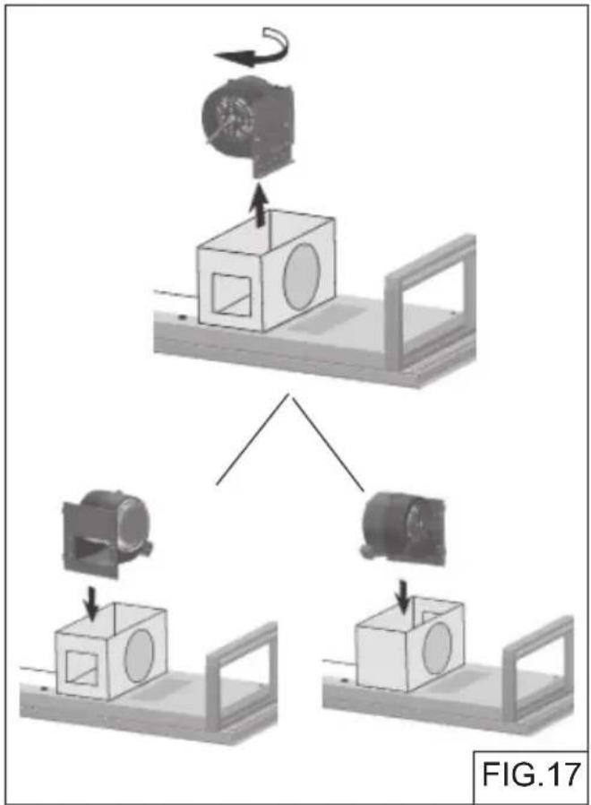
Only CC34IQ63SB model (1 motor):
To change direction of the duct without using elbows.
- Remove (4) screws of the damper collar (Fig.13).
- Remove (2) screws from inside of blower box (Fig.14).
- Remove (4) screws from sides of blower box (Fig.15).
- Remove (10) screws on the top of blower box (Fig.16).
natural_image
Isometric technical drawing of a mechanical assembly with no visible text or symbols
natural_image
3D mechanical assembly diagram showing a cylindrical component mounted on a base plate, with no visible text or symbols.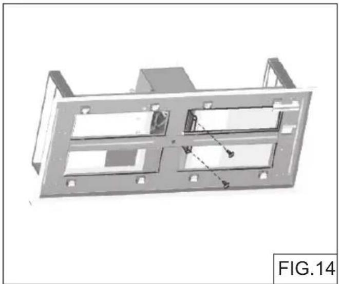
natural_image
3D mechanical component diagram labeled FIG.14, showing internal compartments and mounting holes (no text or symbols on the diagram itself)
natural_image
3D diagram of a rectangular block mounted on a platform with a circular cutout, showing dimension lines (no text or symbols)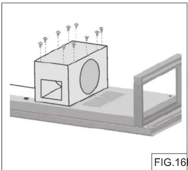
natural_image
3D mechanical assembly diagram showing a cube with circular cutouts and mounting bracket (no text or symbols)FIG.16FIG.15
- Rotate blower 90 degrees and reinstall (2) screws (Fig.17). Reinstall blower box covers, damper and screws.
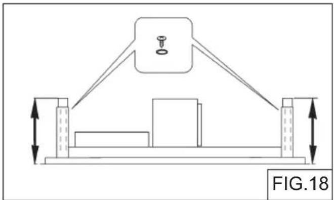
- Adjust height of the telescoping support frame and secure with screws and washers. Fig.18.
CAUTION: Adjust the height before installation. - Lift range hood into the ceiling opening.
- Secure each support frame to the wooden hood support frame using (6) 6 x 60 mm lag bolts and washers provided. Fig. 19.
- Install exterior or in-line blower by following instructions provided with blower.
- Install ductwork and duct tape all joints to ensure an air tight seal.
flowchart
graph TD
    A["Motor Drive"] --> B["Box 1"]
    B --> C["Mounting Box 2"]
    C --> D["Box 3"]
    D --> E["Mounting Box 4"]
    style A fill:#f9f,stroke:#333
    style B fill:#ccf,stroke:#333
    style C fill:#cfc,stroke:#333
    style D fill:#fcc,stroke:#333
    style E fill:#cff,stroke:#333
natural_image
Technical diagram showing a mechanical setup with a central component and two vertical supports, labeled FIG.18 (no text or symbols on the diagram itself)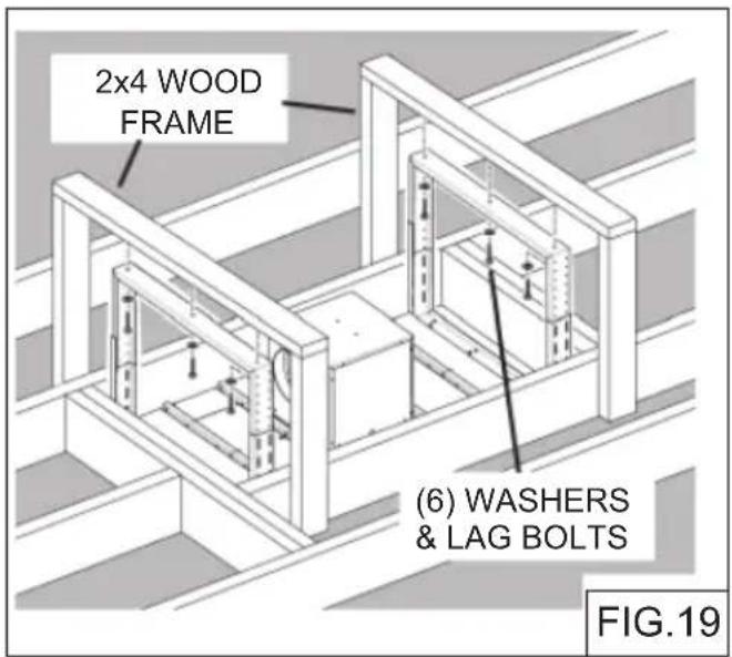
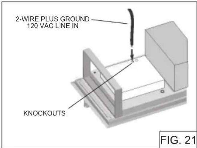
CONNECT THE WIRING


ARNING: All electrical wiring should be done by a qualified person (s) in accordance with all applicable codes and standards. This range hood must be properly grounded.
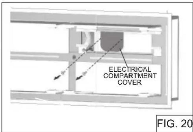
- Remove electrical compartment cover by removing (2) screws (Fig.20).
- Run 2-wire plus ground, 120 VAC electrical power cable to the 34'' knockout located on the back of the hood. Fig. 21.
- Remove 34 " electrical knockout from the back of the hood.
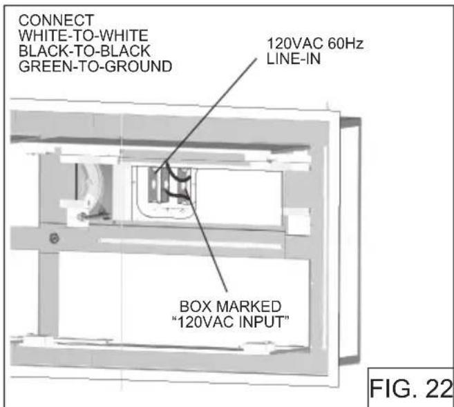
- From the electrical box marked "120 VAC Inlet", remove (2) screws that secure the cover to the metal wiring box. Fig. 22.
- Pull 120VAC electrical power cable into the box and secure with an appropriate cable clamp.
- Make electrical connections inside the box. Connect white-to-white, black-to-black and green-to-ground.
- Replace the wiring box cover and the screws. Reinstall electrical compartment cover and screws. Make sure wires are not pinched between the cover and box.
CAUTION: The hood is compatible only with Broan Make-Up Air Damper Model MD8T (recommended for CC34IQ63SB) or MD10T (recommended for CC34IQT63SB). Purchase separately. Make the connection to the Make-Up Air Damper with low voltage wiring, as shown. See Make-Up Air Damper instructions for additional information (Fig.23)
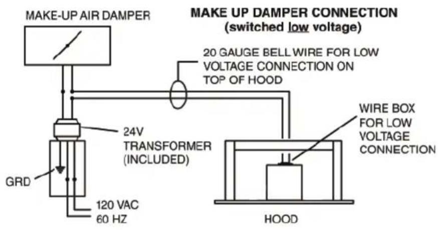
FIG.23
INSTALL THE AIR RETURN VENT (NON-DUCTED VERSION)
Purchase the optional ANKCC3463 recirculating kit, sold separately (Optional for CC34IQ63SB only). The kit includes the air return vent and the charcoal fi Iters.
Fix the air return vent to the ceiling, by means (4) 4,2x15 mm screws. See Fig.24.
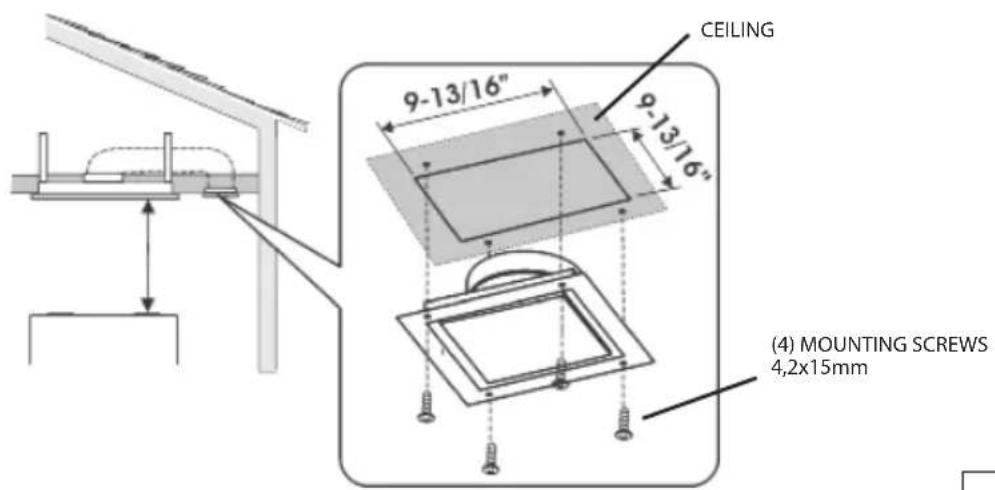
FIG.24
NON-DUCTED RECIRCULATION FILTERS INSTALLATION (NON- DUCTED HOODS ONLY)
Non-ducted recirculation filters are included with kit ANKCC3463. Replacement non-ducted recirculation filters can be purchased separately (AFCCC3463).
Kit and non-ducted recirculation filter are optional for CC34IQ63SB only.
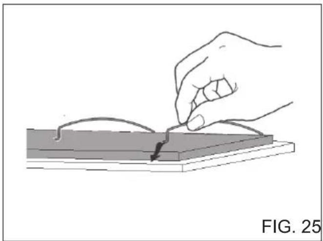
Position the non-ducted recirculation fi Iter over the grease fi Iter and secure it by means (4) wire retainers. Refer Figure 25.
natural_image
Illustration of a hand using a tool to cut or mark a small object on a flat surface, labeled 'FIG. 25' (no other text or symbols)INSTALL THE FILTERS
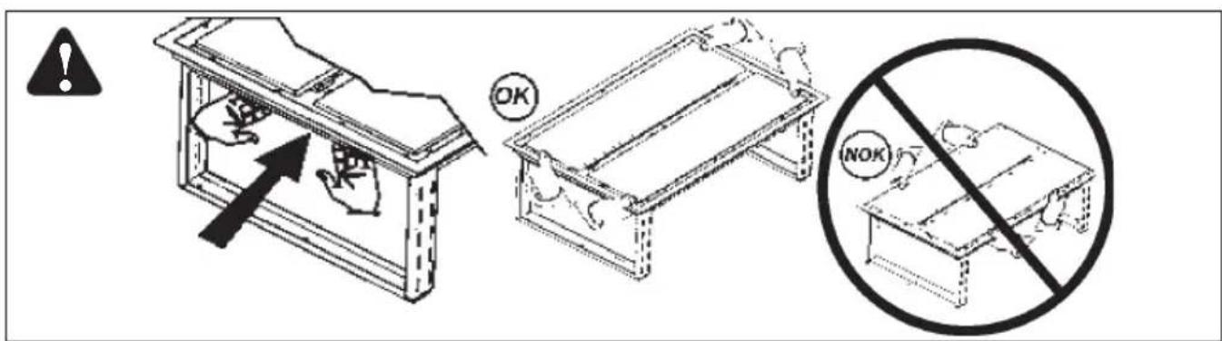
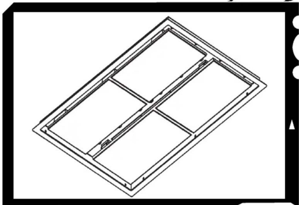
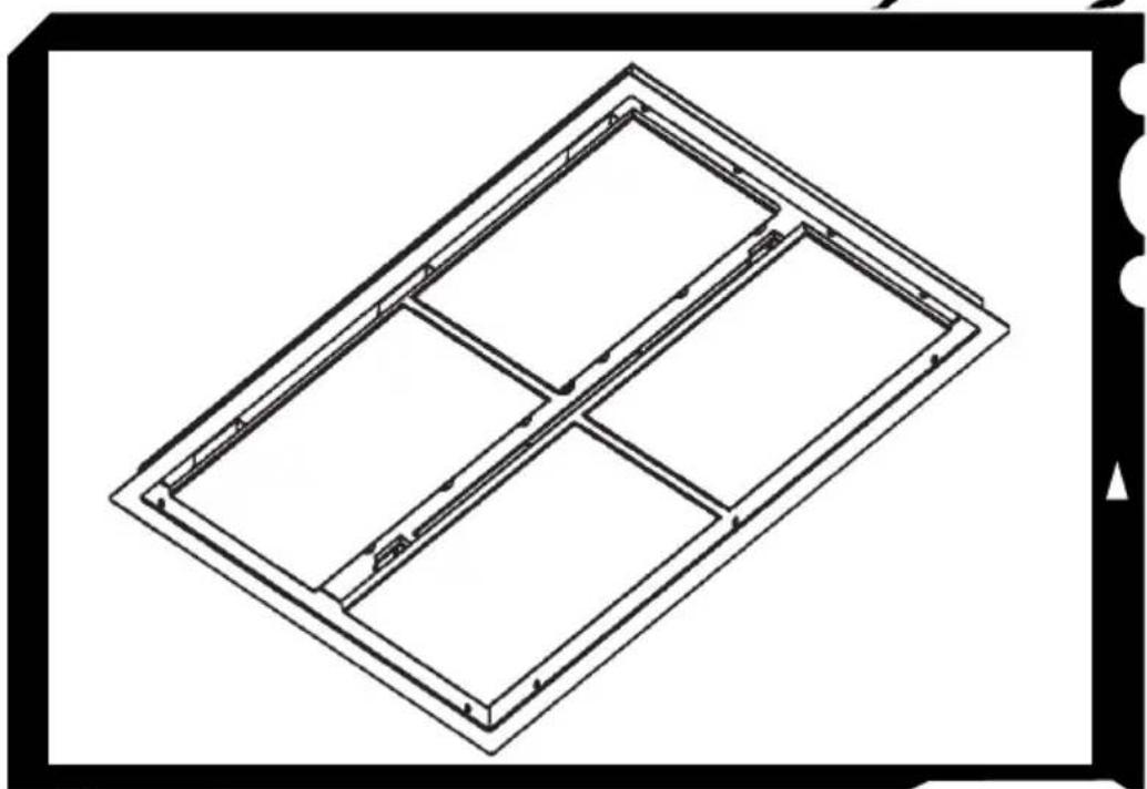
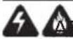
- To install the grease filters, align rear filter tabs with slots in the hood. Push latch tab in, push filter into position and release. Make sure filter is securely engaged after installation. Fig. 26.
- To remove the fi Iters for cleaning, push latch tab in to disengage fi Iter from hood. Tilt the fi Iter downward and remove.
NOTE: Remove protective fi lm from fi Iters and steel surfaces before using cooking under range hood.

natural_image
Technical diagram of a mechanical assembly with internal components and a labeled section (FIG. 26), no readable text or symbols beyond the label.CALIBRATE IQ BLOWER SYSTEM™
After the hood is installed and wired, engage the calibration process (our Guaranteed Performance System Technology to ensure full-rated airflow is being delivered). Prior to calibration, ensure that all fIters, light bulbs and duct system are installed.
CALIBRATION PROCESS Fig. 27
Hold the calibration button for 3 seconds; calibration button will light up and stay on for up to 13 minutes. The blower will start and begin the calibration process. When calibration is complete, one of two things will occur:
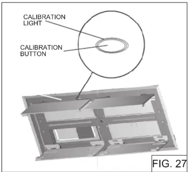
- The blower turns off and calibration button light stays on = Successful calibration. Press the button to turn off the LED. Note: The LED will also turn off if you select any blower speed on the control.
- The blower turns off and calibration button light blinks continuously = Too much restriction in the ductwork is preventing the IQ Blower System™ from achieving the rated airflow. The blower is automatically set to maximum intensity. NOTE: Common items that cause restrictions: restricted damper flap(backdraft damper, wall cap, roof cap), too many elbows, duct size less than 80% of hood outlet, poor transition, use of flex ducting and/or crushed ducting.
Three options are available if your hood system has too much restriction:
- Accept airflow as is.
a. Press the calibration button to accept airflow as is. The IQ Blower System™ is now configured to the highest possible performance. The blinking calibration light goes out. Note: The LED will also turn off if you select any blower speed on the control.
2. Correct duct restriction, clear the original calibration data, and repeat the calibration process.
a. Correct the duct restriction.
b. Clear the original calibration data by holding calibration button for 10 seconds. The light will blink 3 times to confirm and the blower configuration will go back to default settings.
c. Repeat calibration process from the beginning.
- Clear calibration data to reset hood to default factory setting and achieve standard high pressure blower performance.
a. Clear calibration data and reset hood to factory default setting by holding calibration button for 10 seconds. The light will blink 3 times to confirm and the blower configuration will go back to default settings.
Limited Warranty
Warranty Period and Exclusions: Broan-NuTone, LLC(the "Company") warrants to the consumer purchaser of its product ("you") that the product (the "Product") will be free from material defects in the materials or its workmanship for a period of five (5) years from the date of original purchase (or such longer period as may be required by applicable law) or a period of two (2) years from the date of service for any labor provided on the Product.
The limited warranty period for any replacement parts provided by the Company and for any Products repaired or replaced under this limited warranty shall be the remainder of the original warranty period (or such longer period as may be required by applicable law).
THIS WARRANTY DOES NOT EXTEND TO FLUORESCENT LAMP STARTERS, TUBES AND BULBS, FUSES, FILTERS, DUCTS, ROOF CAPS, WALL CAPS AND OTHER ACCESSORIES FOR DUCTING. This warranty does not cover (a) normal maintenance and service, (b) normal wear and tear, (c) any Products or parts which have been subject to misuse, abuse, abnormal usage, negligence, accident, improper or insufficient maintenance, storage or repair (other than repair by the Company), (d) damage caused by faulty installation, or installation or use contrary to recommendations or instructions, (f) damage caused by exposure to salt air, (g) damage in transit, (h) natural wear of finish, (i) Products in commercial or nonresidential use, (j) damage caused by fire, flood or other act of God, or (k) Products with altered, defaced or removed serial numbers. This warranty covers only Products sold to consumers in North America.
This warranty supersedes all prior warranties and, subject to applicable law, is not transferable from the original consumer purchaser.
No Other Warranties: This Limited Warranty contains the Company's sole obligation and your sole remedy for defective Products. The foregoing warranties are exclusive and in lieu of any other warranties and conditions, express or implied. TO THE MAXIMUM EXTENT PERMITTED BY APPLICABLE LAW, THE COMPANY DISCLAIMS AND EXCLUDES ALL OTHER EXPRESS WARRANTIES AND CONDITIONS, AND DISCLAIMS AND EXCLUDES ALL WARRANTIES AND CONDITIONS IMPLIED BY LAW, INCLUDING WITHOUT LIMITATION THOSE OF MERCHANTABILITY AND FITNESS FOR A PARTICULAR PURPOSE. To the extent that applicable law prohibits the exclusion of implied warranties or conditions, the duration of any applicable implied warranty or condition is limited to the period specified for the express warranty above. Some jurisdictions (which may include the Province of Quebec or specific US states) do not allow limitations on how long an implied warranty lasts, so the above limitation may not apply to you. Any oral or written description of the Product is for the sole purpose of identifying it and shall not be construed as an express warranty.
Whenever possible, each provision of this Limited Warranty shall be interpreted in such manner as to be effective and valid under applicable law, but if any provision is held to be prohibited or invalid, such provision shall be ineffective only to the extent of such prohibition or invalidity, without invalidating the remainder of such provision or the other remaining provisions of the Limited Warranty.
Remedy: During the applicable limited warranty period, the Company will, at its option, provide replacement parts for, or repair or replace, without charge, any Product or part thereof, to the extent the Company finds it to be covered by and in breach of this limited warranty under normal use and service. The Company will ship the repaired or replaced Product or replacement parts to you at no charge. You are responsible for all costs for removal, reinstallation and shipping, insurance or other freight charges incurred in the shipment of the Product or part to the Company. If you must send the Product or part to the Company, as instructed by the Company, you must properly pack the Product or part—the Company is not responsible for damage in transit. The Company reserves the right to utilize reconditioned, refurbished, repaired or remanufactured Products or parts in the warranty repair or replacement process. Such Products and parts will be comparable in function and performance to an original Product or part and warranted for the remainder of the original warranty period (or such longer period as may be required by applicable law).
Company reserves the right, in its sole discretion, to refund the money actually paid by you for the Product. If the Product or component is no longer available, replacement may be made with a similar product of equal or greater value, at Company's sole discretion. This is your sole and exclusive remedy for breach of this limited warranty.
Exclusion of Damages: THE COMPANY'S OBLIGATION TO PROVIDE REPLACEMENT PARTS, OR REPAIR OR REPLACE, AT THE COMPANY'S OPTION, SHALL BE YOUR SOLE AND EXCLUSIVE REMEDY UNDER THIS LIMITED WARRANTY AND THE COMPANY'S SOLE AND EXCLUSIVE OBLIGATION. THE COMPANY SHALL NOT BE LIABLE FOR INCIDENTAL, INDIRECT, CONSEQUENTIAL OR SPECIAL DAMAGES ARISING OUT OF OR IN CONNECTION WITH THE PRODUCT, ITS USE OR PERFORMANCE.
Some jurisdictions do not allow the exclusion or limitation of incidental or consequential damages, so the above limitation or exclusion may not apply to you. This warranty gives you specific legal rights, and you may also have other rights, which vary from jurisdiction to jurisdiction. The disclaimers, exclusions, and limitations of liability under this warranty will not apply to the extent prohibited by applicable law.
This warranty covers only replacement or repair of defective Products or parts thereof at the Company's main facility and does not include the cost of fi eld service travel and living expenses.
Any assistance the Company provides to or procures for you outside the terms, limitations or exclusions of this limited warranty will not constitute a waiver of such terms, limitations or exclusions, nor will such assistance extend or revive the warranty.
The Company will not reimburse you for any expenses incurred by you in repairing or replacing any defective Product, except for those incurred with the Company's prior written permission.
How to Obtain Warranty Service: To qualify for warranty service, you must (a) notify the Company at the address or telephone number stated below within seven (7) days of discovering the covered defect, (b) give the model number and part identification and (c) describe the nature of any defect in the Product or part. At the time of requesting warranty service, you must present evidence of the original purchase date. If you cannot provide a copy of the original written limited warranty, then the terms of the Company's most current written limited warranty for your particular product will control.
PRODUCT SPECIFICATIONS
All illustrations and specifications in this catalog are based on the latest product information available at time of production. Broan-NuTone, LLC and BEST® reserves the right to make changes at any time, without notice, in prices, colors, materials, equipment, specifications and models, place of manufacture and to discontinue models or equipment.
Best
Broan-NuTone, LLC- 926 W. State Street, Hartford, WI 53207
1-800-637-1453
Best®, 550 Lemire Blvd., Drummondville, QC, Canada (1-866-737-7770) www.bestrangehoods.com
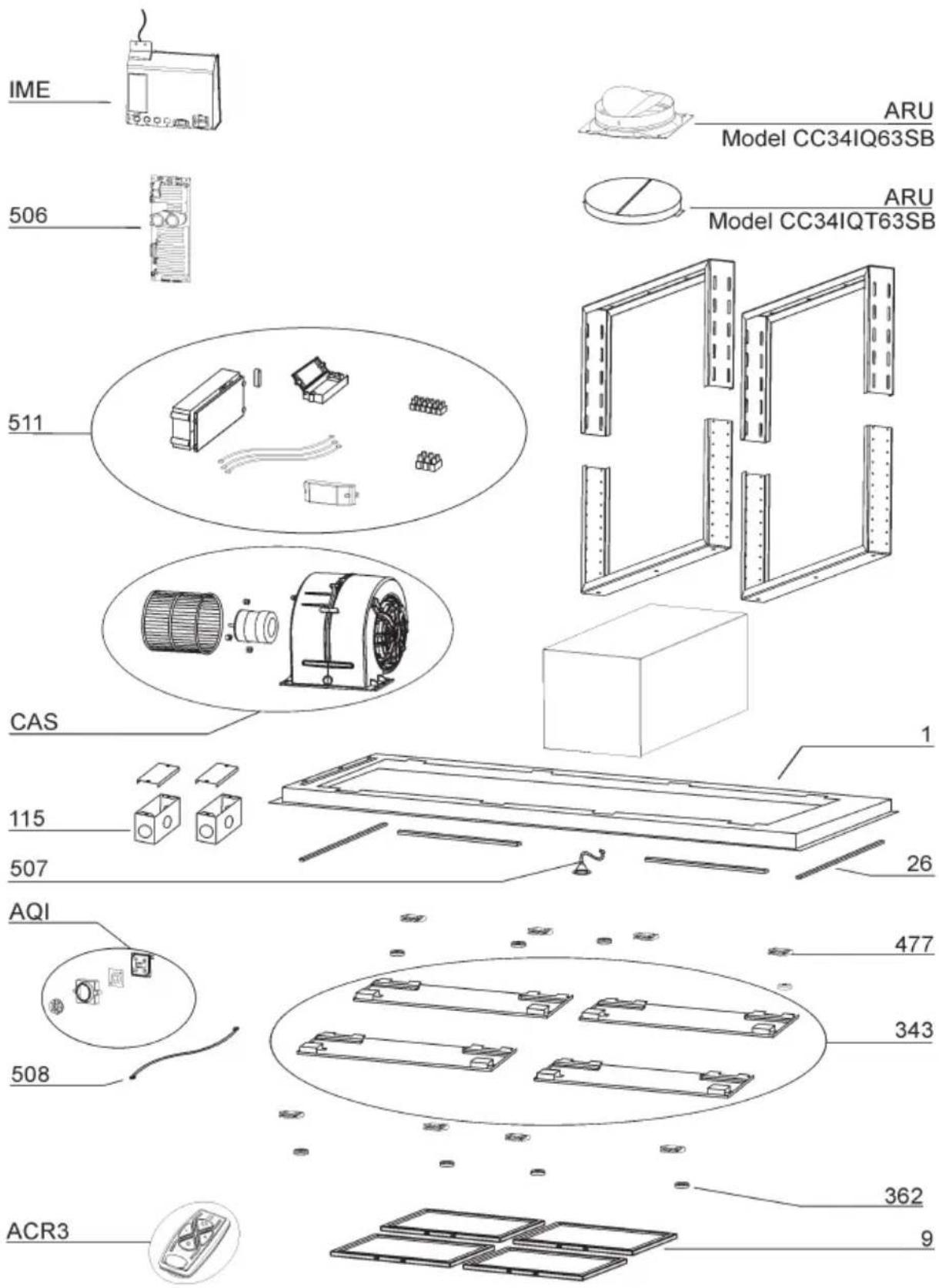
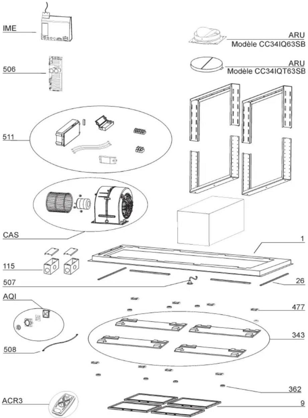
MODEL
CC34IQ63SB
| KEY NO. | PART NO. | DESCRIPTION |
| 1 | B003103711 | FRAME |
| 9 | B08087836 | GREASE FILTER |
| 26 | B023004301 | LIGHT BAR |
| 115 BE3350 | 233 ELECTRICAL BOX | |
| 343 | B08094449 | ELECTRICAL COMPARTMENT COVER |
| 362 | B02011422 | MAGNET |
| 477 | B02011376 | HINGE |
| 506 | B08080878 | BLDC DRIVER |
| 507 | B06102584 | CALIBRATION BUTTON |
| 508 | B02301083 | CONTROL CABLE |
| 511 | B06102814 | DRIVER ASSEMBLY |
| 998 | B080810962 | HARDWARE |
| 999 | B080814337 | INSTALLATION INSTRUCTIONS |
| CAS | B06002259 | BLOWER ASSEMBLY |
| IME B06102 | B05 ELECTRICAL INSTALLATION ASSEMBLY | |
| AQI | B06102812 | SWITCH ASSEMBLY |
| ARU | B08092501 | DAMPER ASSEMBLY |
| ACR3 | B08999186 | REMOTE CONTROL |
| - | B902980139 | NON-DUCTED RECIRCULATION FILTERS |
CC34IQT63SB
| KEY NO. | PART NO. | DESCRIPTION |
| 1 | B003103711 | FRAME |
| 9 | B08087836 | GREASE FILTER |
| 26 | B023004301 | LED |
| 115 BE3350233 | ELECTRICAL BOX | |
| 343 | B08094449 | ELECTRICAL COMPARTMENT COVER |
| 362 | B02011422 | MAGNET |
| 477 | B02011376 | HINGE |
| 506 | B08080879 | BLDC DRIVER |
| 507 | B06102584 | CALIBRATION BUTTON |
| 508 | B02301083 | CONTROL CABLE |
| 511 | B06102806 | DRIVER ASSEMBLY |
| 998 | B080810962 | HARDWARE |
| 999 | B080814337 | INSTALLATION INSTRUCTIONS |
| CAS | B06002259 | BLOWER ASSEMBLY |
| IME B06102805 | ELECTRICAL INSTALLATION ASSEMBLY | |
| AQI | B06102812 | SWITCH ASSEMBLY |
| ARU | B02011533 | DAMPER ASSEMBLY |
| ACR3 | B08999186 | REMOTE CONTROL |
MODEL
CC34IQ63SB
CC34IQT63SB
best®
natural_image
Isometric line drawing of a rectangular frame with internal compartments and arrows indicating direction (no text or symbols)Modèle CC34IQ63SB
CC34IQT63SB
ENGLISH....3
FRANÇAIS......23
ESPAÑOL......45
Au CANADA - BEST Drummondville, QC, Canada
ENREGISTREZ VOTRE PRODUIT EN LIGNE À : www.BestRangeHoods.com/register
Pour de plus amples informations, visitez www.BestRangeHoods.com
LIRE CES DIRECTIVES ET LES CONSERVER

POUR USAGE DOMESTIQUE SEULEMENT


AVERTISSEMENT
POUR RÉDUIRE LES RISQUES D'INCENDIE, D'ÉLECTROCUTION OU DE BLESSURES PHYSIQUES, RESPECTEZ LES INSTRUCTIONS CI-DESSOUS:
natural_image
Pure architectural or engineering diagram showing a beam supported by two vertical posts and a central rectangular structure (no text or symbols)FIG. 1
AFIN DE RÉDUIRE LE RISQUE DE FEU DE CUISINIÈRE
Commandes (Fig.2)
natural_image
Isometric view of a mechanical assembly with two rectangular components mounted on a base plate (no text or symbols visible)BOÎTIER DE LA HOTTE AVEC VOLET

6 RON-
DELLES
natural_image
Line drawing of a rectangular structure with a small square cutout, labeled '4 FILTRES À' at the bottom (no other text or symbols)natural_image
Isometric technical drawing of a mechanical assembly with no visible text or symbols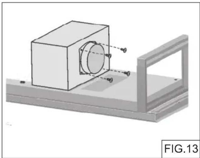
natural_image
3D mechanical assembly diagram showing a cylindrical component mounted on a base plate, with no visible text or symbols.
natural_image
3D mechanical component diagram labeled FIG.14, showing internal compartments and mounting holes (no text or symbols on the diagram itself)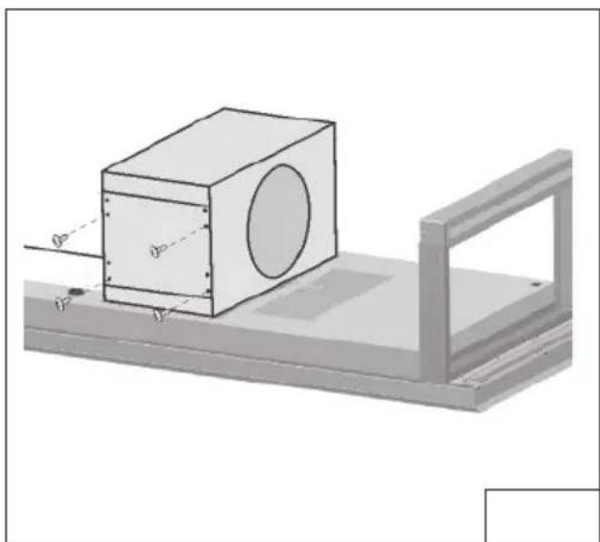
natural_image
3D diagram of a rectangular block mounted on a platform with a circular cutout, showing dimension lines (no text or symbols)
natural_image
3D mechanical assembly diagram showing a cube with circular cutouts and mounting bracket (no text or symbols)FIG.16FIG.15
natural_image
Technical diagram showing a mechanical setup with a central component and two vertical supports, labeled FIG.18 (no text or symbols on the diagram itself)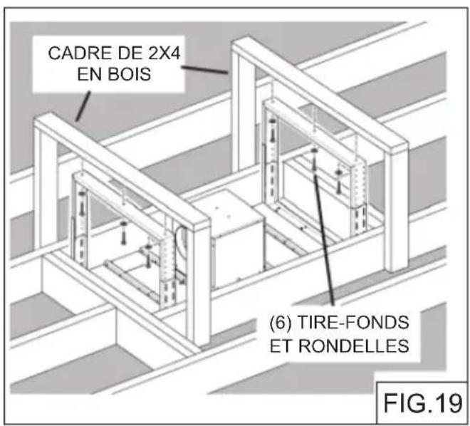
RACCORD DU CÂBLAGE


natural_image
Illustration of a hand using a tool to cut or mark a small object on a flat surface, labeled 'FIG. 25' (no other text or symbols)INSTALLATION DES FILTRES
natural_image
Technical diagram of a mechanical assembly with internal components and mounting holes (no text or symbols)CALIBRER LE VENTILATEUR IQ _MC
SPÉCIFICATIONS DU PRODUIT
Broan-NuTone LLC : 926 W. State Street, Hartford (WI) 53207
1 800 637-1453
Best ^MD , 550, boul. Lemire, Drummondville (Québec), Canada (1 866 737-7770) fr.bestrangehoods.ca
Modèle CC34IQ63SB
| REPÈRE N° DE PIÈCE DESCRIPTION | ||
| 1 | B003103711 | CADRE |
| 9 B08087836 | FILTRE À GRAISSES | |
| 26 | B023004301 | DEL |
| 115 BE3350 | BOÎ TIER DE CONNEXION DU CÂBLE D'ALIMENTATION | |
| 343 B08094 | 449 COUVERCLE DU COMPARTIMENT ELECTRIQUE | |
| 362 | B02011422 | AIMANT |
| 477 | B02011376 | CHARNIERE |
| 506 | B08080878 | CARTE BLDC |
| 507 B06102 | 584 BOUTON DE CALIBRAGE | |
| 508 | B02301083 | CÂBLE COMMANDES |
| 511 | B06102814 | ENSEMBLE COMMANDES |
| 998 | B080810962 ENSEMBLE DE FIXATION | |
| 999 | B080814337 ENSEMBLE DE DIRECTIVES D'INSTALLATION | |
| CAS | B06002259 | ENSEMBLE MOTEUR |
| IME B06102 | 805 ENSEMBLE D'INSTALLATION ÉLECTRIQUE | |
| AQI B06102 | 812 ENSEMBLE DE BOÎ TIER COMMANDES | |
| ARU | B08092501 | ENSEMBLE RACCORD |
| ACR3 | B08999186 | TÉLÉCOMMANDE |
| - | B902980139 | FILTRES À RECIRCULATION |
Modèle CC34IQT63SB
| REPÈRE N° DE PIÈCE DESCRIPTION | ||
| 1 | B003103711 | CADRE |
| 9 B08087836 | FILTRE À GRAISSES | |
| 26 | B023004301 | DEL |
| 115 BE3350 | BOÎ TIER DE CONNEXION DU CÂBLE D'ALIMENTATION | |
| 343 B08094 | 449 COUVERCLE DU COMPARTIMENT ELECTRIQUE | |
| 362 | B02011422 | AIMANT |
| 477 | B02011376 | CHARNIERE |
| 506 | B08080879 | CARTE BLDC |
| 507 B06102 | 584 BOUTON DE CALIBRAGE | |
| 508 | B02301083 | CÂBLE COMMANDES |
| 511 | B06102806 | ENSEMBLE COMMANDES |
| 998 | B080810962 ENSEMBLE DE FIXATION | |
| 999 | B080814337 ENSEMBLE DE DIRECTIVES D'INSTALLATION | |
| CAS | B06002259 | ENSEMBLE MOTEUR |
| IME B06102 | B05 ENSEMBLE D'INSTALLATION ÉLECTRIQUE | |
| AQI B06102 | B12 ENSEMBLE DE BOÎ TIER COMMANDES | |
| ARU | B02011533 | ENSEMBLE RACCORD |
| ACR3 | B08999186 | TÉLÉCOMMANDE |
Modèle
CC34IQ63SB
CC34IQT63SB
best®
natural_image
Isometric line drawing of a rectangular frame with four internal compartments (no text or symbols)Modelo CC34IQ63SB
CC34IQT63SB
ENGLISH....3
FRANÇAIS......23
ESPAÑOL......45
REGISTRE SU PRODUCTO EN LÍNEA EN: www.BestRangeHoods.com/register
Para obtener información adicional visite www.BestRangeHoods.com
LEA Y CONSERVE ESTAS INSTRUCCIONES

PARA COCINAS DOMÉSTICAS SOLAMENTE

ADVERTENCIA
PARA REDUCIR EL RIESGO DE INCENDIOS, DESCARGAS ELÉCTRICAS O LESIONES PERSONALES, RESPETE LO SIGUIENTE:
natural_image
Pure architectural or engineering diagram showing a beam supported by two towers and a central block, with no text, numbers, or symbols present.FIG. 1
PARA REDUCIR EL RIESGO DE INCENDIO PROVOCADO POR GRASA PRESENTE EN LA ESTUFA:
natural_image
Four identical black human silhouette icons arranged horizontally (no text or symbols)

Controles (Fig.2)
FIG. 3 FIG. 4
Remote Control Functions (Fig.3)

Retraso - Apagado

natural_image
Isometric view of a mechanical assembly with two rectangular components mounted on a base plate (no text or symbols visible)CUERPO DE LA CAMPANA

6 ARAN-
DELAS
6 PERNOS DE ROSCA PARA MADERA (6 x 60 mm)
natural_image
Isometric line drawing of a rectangular structure with a small square cutout, labeled '4 FILTROS' (no other text or symbols)4 FILTROS ANTIGRASA
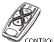
FIG. 5
natural_image
Isometric technical drawing of a mechanical assembly with no visible text or symbols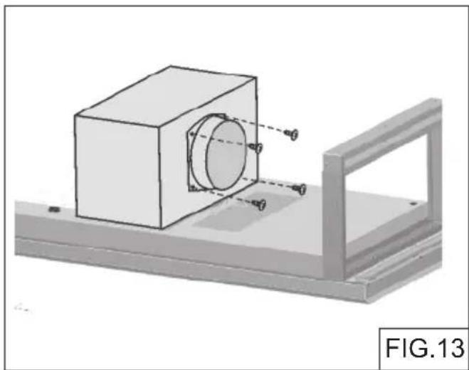
natural_image
3D mechanical assembly diagram showing a cylindrical component mounted on a base plate with a bracket (no text or symbols)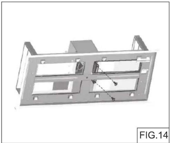
natural_image
3D mechanical component diagram labeled FIG.14, showing internal compartments and mounting holes (no text or symbols on the diagram itself)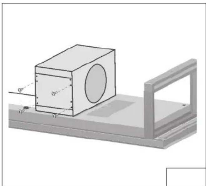
natural_image
3D diagram of a rectangular block with circular cutout and a side view frame, no text or symbols present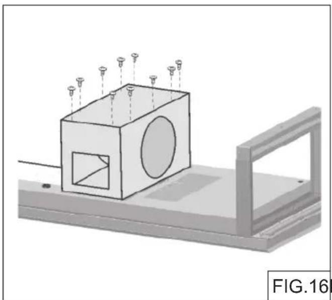
natural_image
3D mechanical assembly diagram showing a cube with circular cutouts and mounting bracket (no text or symbols)FIG.16FIG.15
natural_image
Technical diagram showing a mechanical setup with a central component and two vertical supports, labeled FIG.18 (no text or symbols on the diagram itself)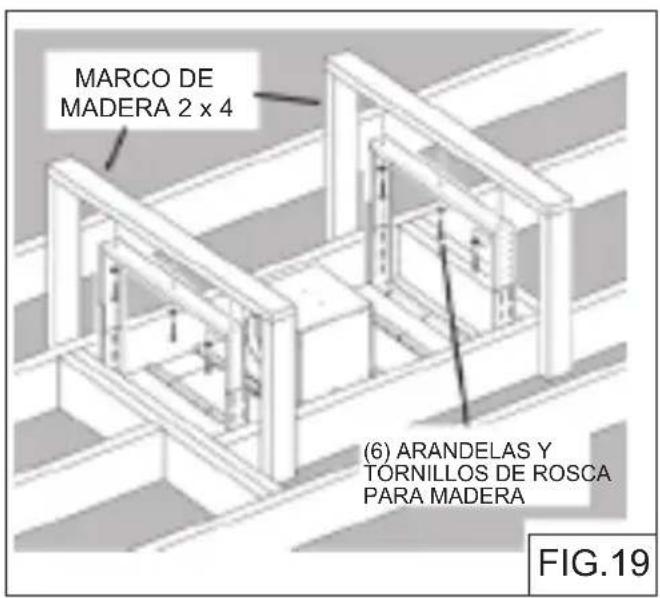
CONECTE EL CABLEADO
natural_image
Illustration of a hand using a tool to cut or mark a small object on a flat surface, labeled 'FIG. 25' (no other text or symbols)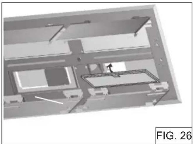
natural_image
Architectural floor plan view showing structural elements and a person walking (no text or symbols)Broan-NuTone, LLC: 926 W. State Street, Hartford, WI 53207
1 800 637-1453
Best®, 550, boul. Lemire, Drummondville (Québec), Canada (1 866 737-7770) www.bestrangehoods.com
Modelo CC34IQ63SB
| CLAVE N.° | PIEZA N.° DESCRIPCIÓN | |
| 1 | B003103711 | MARCO |
| 9 | B08087836 | FILTRO ANTIGRASA |
| 26 | B023004301 | LED |
| 115 BE3350 | 233 CAJ A DE CONEXIÓN DEL CABLE DE ALIMENTACIÓN | |
| 343 B08094 | 449 TAPA DEL COMPARTIMIENTO ELÉCTRICO | |
| 362 | B02011422 | IMÁN |
| 477 | B02011376 | BISAGRA |
| 506 | B08080878 | BLDC DRIVER |
| 507 B06102 | 584 BOTON DE CALIBRACIÓN | |
| 508 B02301 | 1083 CABLE DE COMANDOS | |
| 511 | B06102814 | JUEGO DRIVER |
| 998 | B080810962 JUEGO DE UNIONES | |
| 999 | B080814337 JUEGO DE INSTRUCCIONES PARA INSTALACIÓN | |
| CAS | B06002259 | JUEGO MOTOR |
| IME B06102 | 805 CONJUNTO DE INSTALACIÓN ELÉCTRICA | |
| AQI B06102 | 812 CONJUNTO DE LA CAJA DE COMANDOS | |
| ARU B080 | 92501 JUEGO DE SALIDA DE AIRE | |
| ACR3 | B08999186 | CONTROL REMOTO |
| - | B902980139 | FILTROS DE RECIRCULACIÓN |
Modelo CC34IQT63SB
| CLAVE N.° | PIEZA N.° DESCRIPCIÓN | |
| 1 | B003103711 | MARCO |
| 9 | B08087836 | FILTRO ANTIGRASA |
| 26 | B023004301 | LED |
| 115 BE3350 | 233 CAJ A DE CONEXIÓN DEL CABLE DE ALIMENTACIÓN | |
| 343 B08094 | 449 TAPA DEL COMPARTIMIENTO ELÉCTRICO | |
| 362 | B02011422 | IMÁN |
| 477 | B02011376 | BISAGRA |
| 506 | B08080879 | BLDC DRIVER |
| 507 B06102 | 584 BOTON DE CALIBRACIÓN | |
| 508 B02301 | 083 CABLE DE COMANDOS | |
| 511 | B06102806 | JUEGO DRIVER |
| 998 | B080810962 JUEGO DE UNIONES | |
| 999 | B080814337 JUEGO DE INSTRUCCIONES PARA INSTALACIÓN | |
| CAS | B06002259 | JUEGO MOTOR |
| IME B06102 | 805 CONJUNTO DE INSTALACIÓN ELÉCTRICA | |
| AQI B06102 | 812 CONJUNTO DE LA CAJA DE COMANDOS | |
| ARU B020 | 11533 JUEGO DE SALIDA DE AIRE | |
| ACR3 | B08999186 | CONTROL REMOTO |
Modelo
CC34IQ63SB
CC34IQT63SB

- Model CC34IQ63SB CC34IQT63SB
- READ AND SAVE THESE INSTRUCTIONS
- TO REDUCE THE RISK OF INJURY TO PERSONS IN THE EVENT OF A RANGE TOP GREASE FIRE, OBSERVE THE FOLLOWING:\*
- CAUTION
- Controls (Fig.2)
- (P1) Delay- Off Switch
- (P2) Filter Alarm Switch
- (P3) Blower Speed Decrease and Off Switch
- (P4) Blower Speed Increase and On Switch
- (P5) Light Switch
- To Link Remote Control to Hood
- Remote Control Functions (Fig.3)
- Battery disposal
- Motor
- Grease Filter
- Stainless Steel Cleaning
- DO:
- DON'T:
- Avoid: When choosing a detergent
- PREPARE THE HOOD
- INSTALL THE DUCTWORK
- PREPARE THE CEILING OPENING
- PREPARE THE HOOD SUPPORT
- INSTALL THE HOOD
- CONNECT THE WIRING
- INSTALL THE AIR RETURN VENT (NON-DUCTED VERSION)
- NON-DUCTED RECIRCULATION FILTERS INSTALLATION (NON- DUCTED HOODS ONLY)
- INSTALL THE FILTERS
- CALIBRATE IQ BLOWER SYSTEM™
- CALIBRATION PROCESS Fig. 27
- Limited Warranty
- PRODUCT SPECIFICATIONS
- Best
- best®
- Modèle CC34IQ63SB
- CC34IQT63SB
- LIRE CES DIRECTIVES ET LES CONSERVER
- POUR USAGE DOMESTIQUE SEULEMENT
- AVERTISSEMENT
- AFIN DE RÉDUIRE LE RISQUE DE FEU DE CUISINIÈRE
- Commandes (Fig.2)
- RACCORD DU CÂBLAGE
- INSTALLATION DES FILTRES
- CALIBRER LE VENTILATEUR IQ _MC
- SPÉCIFICATIONS DU PRODUIT
- Modelo CC34IQ63SB
- LEA Y CONSERVE ESTAS INSTRUCCIONES
- PARA COCINAS DOMÉSTICAS SOLAMENTE
- ADVERTENCIA
- PARA REDUCIR EL RIESGO DE INCENDIO PROVOCADO POR GRASA PRESENTE EN LA ESTUFA:
- Controles (Fig.2)
- CONECTE EL CABLEADO
Brand : BEST
Model : CC34IQT63SB
Category : Range hood