
PKEX2245 - Range hood BEST - Free user manual and instructions
Find the device manual for free PKEX2245 BEST in PDF.

| Product Type | Built-in Range Hood |
| Brand | BEST |
| Model | PKEX2245 |
| Width | 45 in (114.3 cm) |
| Weight (with internal blower) | 57 lb (25.9 kg) |
| Weight (with external/inline blower) | 39 lb (17.7 kg) |
| Power Supply | 120 V, 60 Hz |
| Lighting Power | 120 V, 50 W PAR16 GU10 base halogen bulbs (3 bulbs) |
| Number of Fan Speeds | 4 |
| Ventilation Technology | IQ™ Fan with Auto Calibration |
| Maximum Airflow | Up to 1200 CFM (depending on blower) |
| Special Features | Delayed Shut-Off (10 min), Heat Sentry™, Speed and Light Memory |
| Filter Type | Hybrid Baffle Filters with Micro-Mesh and Handles (2 filters, 17 in × 10 in) |
| Filter Maintenance | Dishwasher Safe (phosphate-free detergent) |
| Minimum Distance Above Cooking Surface | 24 in (61 cm) |
| Recommended Distance Above Cooking Surface | 30 in (76 cm) |
| Recommended Ventilation Type | 10 in Round Rigid Metal Duct (exterior exhaust) |
| Blower Compatibility (PKEX22 series) | External blowers EB6, EB9, EB12, EB15 or inline blowers ILB3, ILB6, ILB9, ILB11 |
| Hood Material | Stainless Steel |
| Motor Thermal Protection | Yes (auto shut-off in case of overheating) |
| Optional Remote Control | ACR2 Series (sold separately) |
| Warranty | 5 Years (Limited) |
Frequently Asked Questions - PKEX2245 BEST
User questions about PKEX2245 BEST
0 question about this device. Answer the ones you know or ask your own.
Ask a new question about this device
Download the instructions for your Range hood in PDF format for free! Find your manual PKEX2245 - BEST and take your electronic device back in hand. On this page are published all the documents necessary for the use of your device. PKEX2245 by BEST.
USER MANUAL PKEX2245 BEST
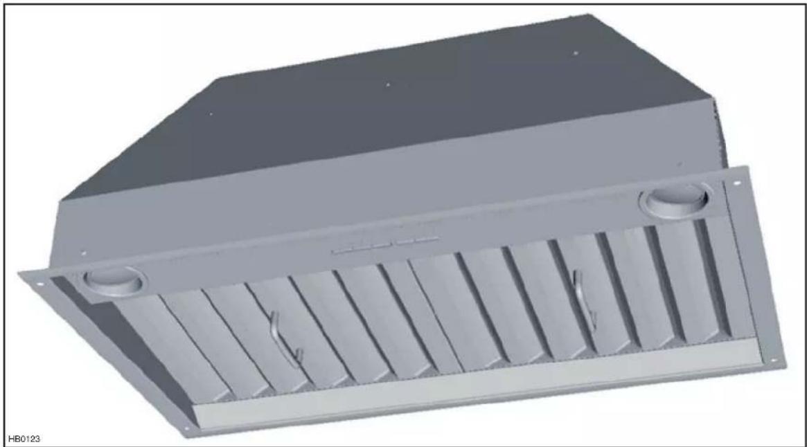
natural_image
3D rendering of a rectangular industrial enclosure with slatted ventilation grilles and two circular openings (no text or symbols visible)PK22 AND PKEX22 SERIES
READ AND SAVE THESE INSTRUCTIONS
INSTALLER: LEAVE THIS MANUAL WITH HOMEOWNER. HOMEOWNER: USE AND CARE INFORMATION ON PAGES 11 TO 13.
BEST; Hartford, Wisconsin www.BestRangeHoods.com 800-558-1711
BEST; Drummondville, QC, Canada www.BestRangeHoods.ca 866-737-7770
To register your product online or for additional information visit www.BestRangeHoods.com
TO REDUCE THE RISK OF FIRE, ELECTRIC SHOCK OR INJURY TO PERSONS, OBSERVE THE FOLLOWING:
- Use this unit only in the manner intended by the manufacturer. If you have questions, contact the manufacturer at the address or telephone number listed in the warranty.
- Before servicing or cleaning unit, switch power off at service panel and lock service disconnecting means to prevent power from being switched on accidentally. When the service disconnecting means cannot be locked, securely fasten a prominent warning device, such as a tag, to the service panel.
- Installation work and electrical wiring must be done by qualified personnel in accordance with all applicable codes and standards, including fire-rated construction codes and standards.
- Sufficient air is needed for proper combustion and exhausting of gases through the flue (chimney) of fuel burning equipment to prevent backdrafting. Follow the heating equipment manufacturer's guidelines and safety standards such as those published by the National Fire Protection Association (NFPA) and the American Society for Heating, Refrigeration and Air Conditioning Engineers (ASHRAE) and the local code authorities.
- When cutting or drilling into wall or ceiling, do not damage electrical wiring and other hidden utilities.
- Ducted fans must always be vented to the outdoors.
- Do not use this unit with any solid-state speed control device.
- To reduce the risk of fire, use only metal ductwork.
- This unit must be grounded.
- When applicable local regulations comprise more restrictive installation and/or certification requirements, the aforementioned requirements prevail on those of this document and the installer agrees to conform to these at his own expenses.
TO REDUCE THE RISK OF A RANGE TOP GREASE FIRE:
a) Never leave surface units unattended at high settings. Boilovers cause smoking and greasy spillovers that may ignite. Heat oils slowly on low or medium settings.
b) Always turn power pack ON when cooking at high heat or when flambeing food (i.e.: Crêpes Suzette, Cherries Jubilee, Peppercorn Beef Flambé).
c) Clean ventilating fans frequently. Grease should not be allowed to accumulate on fan, filters or in exhaust ducts.
d) Use proper pan size. Always use cookware appropriate for the size of the surface element.
TO REDUCE THE RISK OF INJURY TO PERSONS IN THE EVENT OF A RANGE TOP GREASE FIRE, OBSERVE THE FOLLOWING\*:
- SMOTHER FLAMES with a close-fitting lid, cookie sheet or metal tray, then turn off the burner. BE CAREFUL TO PREVENT BURNS. IF THE FLAMES DO NOT GO OUT IMMEDIATELY, EVACUATE AND CALL THE FIRE DEPARTMENT.
- NEVER PICK UP A FLAMING PAN — You may be burned.
- DO NOT USE WATER, including wet dishcloths or towels — This could cause a violent steam explosion.
- Use an extinguisher ONLY if:
A. You own a Class ABC extinguisher and you know how to operate it.
B. The fire is small and contained in the area where it started.
C. The fire department has been called.
D. You can fight the fire with your back to an exit.
* Based on "Kitchen Fire Safety Tips" published by NFPA.
CAUTION
- For indoor use only.
- For general ventilating use only. Do not use to exhaust hazardous or explosive materials and vapors.
- To avoid motor bearing damage and noisy and/or unbalanced impellers, keep drywall spray, construction dust, etc. off power unit.
- Your power pack motor has a thermal overload which will automatically shut off the motor if it becomes overheated. The motor will restart when it cools down. If the motor continues to shut off and restart, have the power pack serviced.
- The minimum power pack distance above cooktop must not be less than 24". A maximum of 30" above cooktop is recommended for best capture of cooking impurities.
- Two installers are recommended because of the large size and weight of this unit.
- To reduce the risk of fire and to properly exhaust air, be sure to duct air outside — Do not exhaust air into spaces within walls or ceiling or into attics, crawl space or garage.
- This product is equipped with a thermostat which may start blower automatically. To reduce the risk of injury and to prevent power from being switched on accidentally, switch power off at service panel and lock or tag service panel.
- Because of the high exhausting capacity of this unit, you should make sure enough air is entering the house to replace exhausted air by opening a window close to or in the kitchen.
- To reduce the risk of fire and electrical shock, the Best models PK22 series should only be installed with their own built-in blowers, and the Best models PKEX22 Series must only be installed with Best external blower models EB6, EB9, EB12 or EB15; or Best in-line blowers models ILB3, ILB6, ILB9, ILB11. Other blowers cannot be substituted.
- PKEX22 models used with ILB3, ILB6 or EB6 blower, must be installed over ranges rated 60,000 Btu/hr. maximum.
- Please read specification label on product for further information and requirements.
-
This power pack is equipped with a RF receiver (optional remote control sold separately). Changes or modifications not expressly approved by the party responsible for compliance could void the user's authority to operate this product. The remote control has been tested and found to comply with the limits for a Class B digital device, pursuant to part 15 of the FCC Rules and the Canadian ICES-003. These limits are designed to provide reasonable protection against harmful interference in a residential installation. The remote control generates, uses and can radiate radio frequency energy and, if not installed and used in accordance with the instructions, may cause harmful interference to radio communications. However, there is no guarantee that interference will not occur in a particular installation. If this equipment does cause harmful interference to radio or television reception, which can be determined by turning the equipment off and on, the user is encouraged to try to correct the interference by one or more of the following measures:
-
Reorient or relocate the receiving antenna
- Increase the separation between the equipment and receiver
- Connect the equipment into an outlet on a circuit different from that to which the receiver is connected
For a PKEX22 series power pack, either an external blower or in-line blower must be used. The PKEX22 series power pack must be installed with blower models ILB3, ILB6, ILB9, ILB11, EB6, EB9, EB12 or EB15 only. Other blowers cannot be substituted (blowers sold separately.)
If installing external or in-line blower, refer to instructions packed with blower and follow steps 1 to 6, 11 to 16, 18 and up of this manual.
Plan where and how the ductwork will be installed.
A straight, short duct run will allow the power pack to perform most efficiently. Long duct runs, elbows and transitions will reduce the performance of the power pack. Use as few of them as possible. Larger ducting may be required for longer duct runs.
Install proper-sized ductwork, elbows and roof or wall cap for the type of blower you are installing. Connect metal ductwork to cap and work back towards the hood location. Use 2" metal foil duct tape to seal the joints.
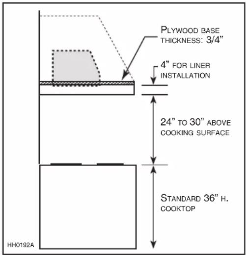
The minimum power pack distance above cooktop must not be less than 24". A maximum of 30" above cooktop is recommended for best capture of cooking impurities.
Distances over 30" are at the installer and users discretion.
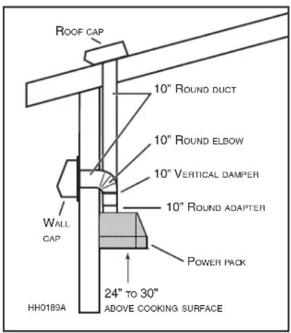
PK22 DUAL INTERNAL BLOWER TYPICAL DUCTWORK
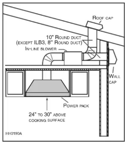
PKEX22 EXTERNAL BLOWER
TYPICAL DUCTWORK
NOTE: For external blowers mounted in close proximity to power pack, sound level may be higher than specified for internal blowers.
2. PREPARE THE INSTALLATION
WARNING
When performing installation, servicing or cleaning the unit, it is recommended to wear safety glasses and gloves.
NOTE: Before proceeding to the installation, check the contents of the box. If items are missing or damaged, contact the manufacturer.
Make sure that the following items are included:
- Power pack
- Installation instructions
- Accessories: • 2 Hybrid baffle filters with handles
- Shielded halogen bulbs (120 V, 50 W with GU10 base)
(2 for 30" and 39" width power packs, 3 for 45" width power pack)
- 10" round adapter and 10" round damper (included with PK22 power pack series only, not with PKEX22 series)
- Bag of parts including: 1 wire clamp, 2 wire connectors, 2 no. 8 x 3/8" screws, 6 no. 8-18 x 1¼" chrome plated screws.
If applicable, discard extra screws.
2. PREPARE THE INSTALLATION (CONT'D)
Parts sold separately:
- In-line blower assembly model ILB3, ILB6, ILB9 or ILB11.
- External blower assembly model EB6, EB9, EB12 or EB15.
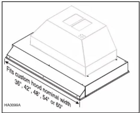
- Custom hood liner model AL3036, AL3042, AL3948, AL3954, AL4554 or AL4560 (optional).
- ACR Series remote control (optional).
- Ducts, elbows, wall or roof caps. Refer to pages 3 and 4 for a complete list of venting options and model numbers.
- 10" round adapter with rough-in plate kit for PKEX22 series models (included with in-line or external blower kits).
NOTE: During installation, protect countertop and/or cooktop.
3. PREPARE CUSTOM HOOD
WARNING
- When building a custom hood, always follow all applicable construction codes and standards.
- Make sure the cabinet is capable of supporting its own weight and the weight of the power pack. Failure to do so may cause personal injury or damage to countertop or cooktop.
The custom hood must be constructed to fit the size and shape of the power pack. Proper structural support is required to accommodate the weight of the hood.
Start with the custom hood base, because its position will determine the height of the power pack. We recommend the base of the custom hood should be 3/4-inch thick plywood. If an optional custom hood liner will be installed, we recommend the sides and front of the custom hood to be 3/4-inch thick, assuming standard cabinet width. If the optional custom hood liner will not be installed, the custom hood side and front thickness is at the installer's discretion.
Run power cable to installation location. Stub out a 4-foot length of electrical cable below the custom hood.
| POWER PACK WIDTH | WITH INTERNAL BLOWER | WITH IN-LINE OR EXTERNAL BLOWER |
| 30" 50 LB. | - | |
| 39" 54 LB. 36 LB. | ||
| 45" 57 LB. 39 LB. |
4. INSTALL CUSTOM HOOD LINER (OPTIONAL)
The liners are especially designed to protect the exterior base of the custom hood. Refer to the table below to find the right liner model number for your power pack and custom hood width. To view specifications, including depth for each liner model, visit www.BestRangeHoods.com or contact Technical support (phone number listed on page 13, in warranty text).
To install, see instructions packed with custom hood liner. The liner must be installed before the power pack.
NOTE: On some liner models, the front liner piece may overlap the power pack front flange. If so, remove the front liner piece, assemble power pack, and reassemble the front liner piece.
| LINER MODEL | POWER PACK MODEL | CUSTOM HOOD NOMINAL WIDTH |
| AL3036 | PK2230 36" | |
| AL3042 | PK2230 42" | |
| AL3948 | PK2239/PKEX2239 | 48" |
| AL3954 | PK2239/PKEX2239 | 54" |
| AL4554 | PK2245/PKEX2245 | 54" |
| AL4560 | PK2245/PKEX2245 | 60" |
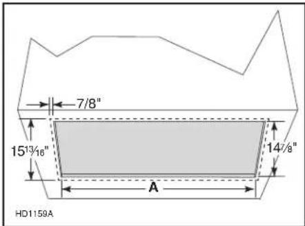
5. CUT HOLE IN CUSTOM HOOD BASE
If it is not done yet, cut a hole in the bottom of the cabinet, using the dimensions shown below.
| POWER PACK WIDTH A | |
| 30" 26 | 316" |
| 39" 34 | 15116" |
| 45" 41 | 78" |
NOTE: The 15 ^13/16 " and 7/8" measurements show the power pack flange.
6. REMOVE HYBRID BAFFLE FILTERS
Remove tape on filters. Remove filters from power pack and set aside.
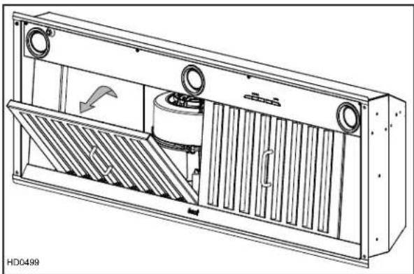
natural_image
Technical line drawing of a mechanical ventilation unit with cooling fins and ventilation ducts (no text or symbols)7. REMOVE ELECTRICAL COMPARTMENT COVER (PK22 SERIES ONLY)
From inside the power pack, remove the wiring cover by removing its retaining screw and set aside.
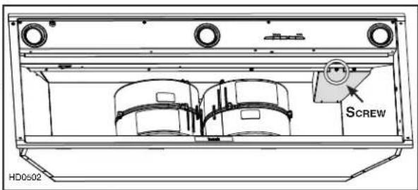
8. INSTALL WIRE CLAMP (PK22 SERIES ONLY)
Install the wire clamp (included in parts bag) on top of the power pack.
natural_image
Technical line drawing of a mechanical component with two circular inset views (no text or symbols)9. INSTALL 10" ADAPTER (PK22 SERIES ONLY)
Using 2 no. 8 x 3/8" screws from parts bag, assemble the adapter on the top of the power pack. Seal all joints with metal foil duct tape to eliminate air leaks.
10. INSTALL 10" DAMPER (PK22 SERIES ONLY)
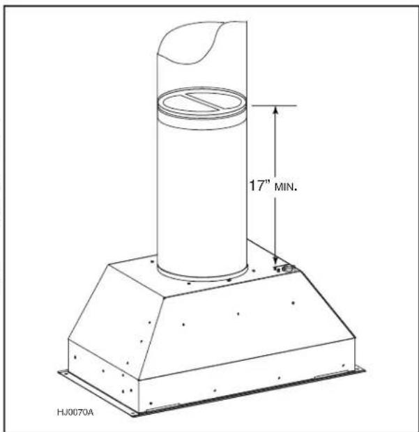
Install 10" damper (model 421, provided with PK22 series power packs) inside the vertical ductwork that will be attached to the power pack. Do not install in a horizontal ductwork or directly on top of the adapter or it will not open and close properly. Remove shipping tape if present. Secure the damper to the duct with 3 no. 8 sheet metal screws (not provided). Ensure the damper opens and closes freely. Seal all joints with metal foil duct tape to eliminate air leaks.
NOTE: To optimize airflow and reduce noise, position the damper at least 17" above the top of the power pack; or as far as the duct run will allow (see figure at right).
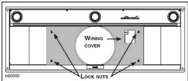
11. INSTALL ROUGH-IN PLATE FOR EXTERNAL BLOWER (PKEX22 SERIES ONLY)
Refer to the instructions included with the selected blower/rough-in kit (sold separately) for details on installing the rough-in plate. Install the rough-in plate so that the wiring box is located on the right side when facing the hood, as specified on the blower housing label.
12. CONNECT WIRING (ALL MODELS)
WARNING
Risk of electric shock. Electrical wiring must be done by qualified personnel in accordance with all applicable codes and standards. Before connecting wires, switch power off at service panel and lock service disconnecting means to prevent power from being switched on accidentally.
Position the power pack below its custom hood.
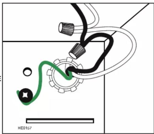
INTERNAL BLOWERS: Insert the house wiring cable through the wire clamp previously installed in step 8. Tighten the wire clamp to secure the cable. Connect cable into electrical compartment using included wire connectors. Connect BLACK to BLACK, WHITE to WHITE and GREEN or bare wire under green ground screw. DO NOT FORGET TO CONNECT THE GROUND. Reinstall electrical compartment cover.
IN-LINE OR EXTERNAL BLOWERS: See instructions included with blower.
natural_image
Diagram of a mechanical or electrical component with no visible text, numbers, or symbols13. CONNECT DUCTING (ALL MODELS)
A. When there is access to the top of the hood, connect ductwork and seal connections with metal foil duct tape after Step 14 Install power pack.
B. When there is no access to the top of the hood, carefully pull down the metal duct through the custom hood base hole. Slide this duct over the adapter (internal blower) or over the flange of the rough-in plate (in-line or external blower). Make sure the adapter/damper assembly enters the ducting. Seal joint with metal foil duct tape.
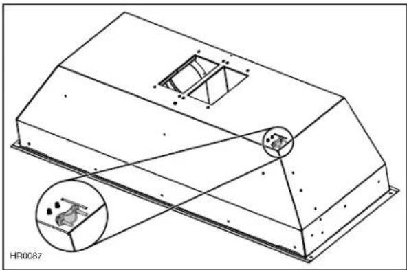
14. INSTALL POWER PACK
CAUTION
Take care not to kink ducting when installing the power pack.
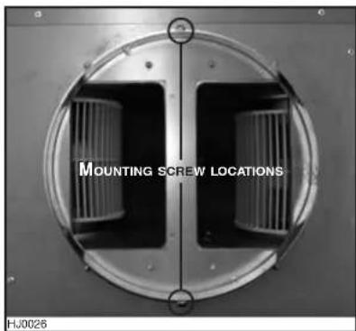
TIP: Two of the six no. 8-18 x 1¼" provided chrome plated screws can be used to temporarily support the power pack during installation. Place the power pack inside the custom hood and insert both side screws. The power pack can now be secured to the custom hood without having to hold it in place.
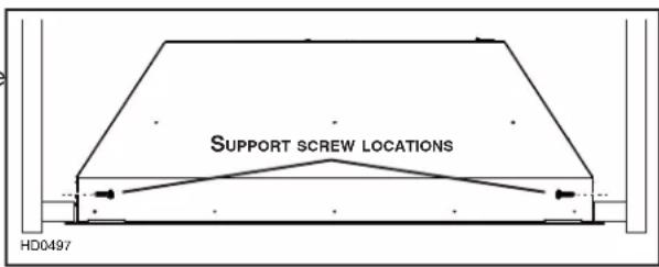
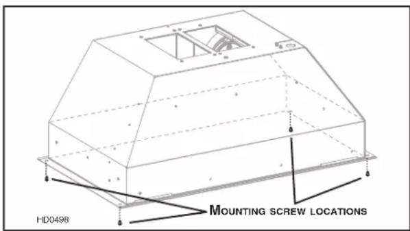
Using provided no. 8-18 x 1¼" chrome plated screws, secure the power pack inside the custom hood. Install 1 screw at each corner. (See figure at right for mounting screw locations.)
15. INSTALL BLOWER (PKEX22 SERIES ONLY)
WARNING
Do not plug the two cords together.
To install, see instructions packed with blower.
Once the blower is installed, plug the blower cord (B) into the female receptacle and the power supply cord (A) onto the male connector inside the power pack.

natural_image
Two black electrical connectors labeled A and B, connected by wires (no text or symbols on the connectors themselves)16. REINSTALL HYBRID BAFFLE FILTERS
CAUTION
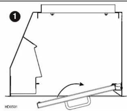
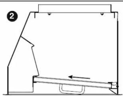
Remove protective plastic film covering hybrid baffle filters before installing them.
① Insert one end of the hybrid baffle filter into the back channel of the power pack.
② Raise the other end toward the inside and insert in the front channel of the power pack.
Replacement filters are available from your dealer. See label inside power pack for part number.
natural_image
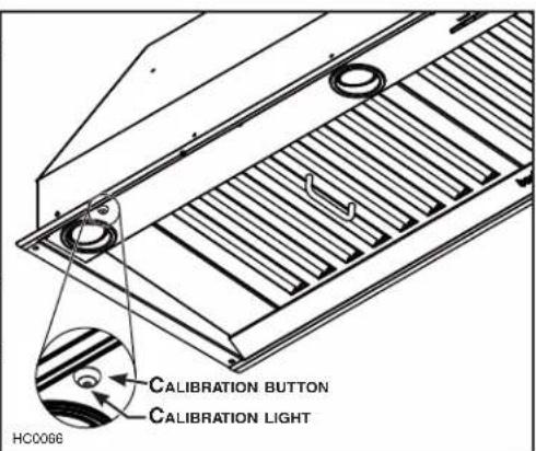
Technical line drawing of a mechanical assembly with no visible text or symbols17. CALIBRATE IQ BLOWER SYSTEM™ (PK22 SERIES ONLY)
After the power pack is installed and wired, engage the calibration process (our Guaranteed Performance System Technology to ensure full-rated airflow is being delivered). Prior to calibration, ensure that all filters, light bulbs and duct system are installed.
CALIBRATION PROCESS
Hold the calibration button for 3 seconds; calibration button will light up and stay on for up to 13 minutes. The blower will start and begin the calibration process. When calibration is complete, one of two things will occur:
A. The blower turns off and calibration button light stays on = Successful calibration. Press the button to turn off the LED. NOTE: The LED will also turn off if you select any blower speed on the control.
B. The blower turns off and calibration button light blinks continuously = Too much restriction in the ductwork is preventing the IQ Blower System™ from achieving the rated airflow. The blower is automatically set to maximum intensity.
NOTE: Common items that cause restrictions: restricted damper flap (backdraft damper, wall cap, roof cap), too many elbows, duct size less than 80% of hood crushed ducting.
Three options are available if your power pack system has too much restriction:
- Accept airflow as is. Press the calibration button to accept airflow as is. The IQ Blower System™ is now configured to its highest possible performance. The blinking calibration light goes out. NOTE: The LED will also turn off if you select any blower speed on the control.
- Correct duct restriction, clear the original calibration data, and repeat the calibration process.
a. Correct the duct restriction.
b. Clear the original calibration data by holding calibration button for 10 seconds. The light will blink 3 times to confirm and the blower configuration will go back to default settings.
c. Repeat calibration process from the beginning.
- Clear calibration data to reset power pack to default factory settings and achieve standard high pressure blower performance by holding calibration button for 10 seconds. The light will blink 3 times to confirm and the blower configuration will go back to default settings.
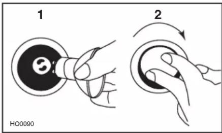
18. LIGHT BULBS
This power pack requires shielded halogen lamps (120 V, 50 W, PAR16 with GU10 base, 2 for 30" and 39" width power packs, 3 for 45" width power pack), included.
NOTE: Before using lamps, remove shipping tape on them (if present).
WARNING
Do not touch lamps during or soon after operation. Burns may occur. In order to prevent the risk of personal injury, only install shielded halogen lamps. Also, never install a cool beam, a dichroic lamp, a lamp not suitable for use in recessed luminaires or identified for use in enclosed fixtures.
- Install the lamps by placing the bulb leads into their grooves in the socket.
- Gently push upwards and turn clockwise until secure.
To remove lamps, gently push upwards and turn counterclockwise to disengage bulb leads from their grooves.
NOTE: If need be, use a rubber dishwashing glove to add grip when removing the bulb; or use suction cup tool available from Best to ease removal of the bulbs. Contact Best Customer Service at 1-800-558-1711 to order suction cup tool, part number 99526707.
19. USE AND CARE
Hybrid Baffle Filters
The hybrid baffle filters should be cleaned frequently. Use a warm detergent solution. Wash more often if your cooking style generates greater grease — like frying foods or wok cooking.
Remove hybrid baffle filters by pushing them towards the back of power pack and rotating filters downward. Baffle filters are dishwasher safe. Allow filters to dry completely before reinstalling them in the power pack.
Clean all-metal filters in the dishwasher using a non-phosphate detergent. Discoloration of the filter may occur if using phosphate detergent or as a result of local water conditions — but this will not affect filter performance. This discoloration is not covered by the warranty.
Internal Blowers Cleaning
Remove filters in order to access blowers. Vacuum blowers to clean. Do not immerse in water.
Power Pack Cleaning
Stainless steel cleaning:
| Do:Regularly wash with clean cloth or rag soaked with warm water and mild soap or liquid dish detergent.Always clean in the direction of original polish lines.Always rinse well with clear water (2 or 3 times) after cleaning.Wipe dry completely.You may also use a specialized household stainless steel cleaner. | Don't:Use any steel or stainless steel wool or any other scrapers to remove stubborn dirt.Use any harsh or abrasive cleansers.Allow dirt to accumulate.Let plaster dust or any other construction residues reach the power pack. During construction/renovation, cover the power pack to make sure no dust sticks to stainless steel surface. |
Avoid when choosing a detergent:
- Any cleaners that contain bleach will attack stainless steel.
- Any products containing: chloride, fluoride, iodide, bromide will deteriorate surfaces rapidly.
- Any combustible products used for cleaning such as acetone, alcohol, ether, benzol, etc., are highly explosive and should never be used close to a range.
20. OPERATION
Always turn your blower on before you begin cooking to establish an airflow in the kitchen. Let the blower run for a few minutes to clear the air after you turn off the range.
A) Blower delay-off button
B) ON blower/Speed control button
C) OFF blower!
Filter maintenance button
D) OFF lighting
E) ON light button (3 settings)
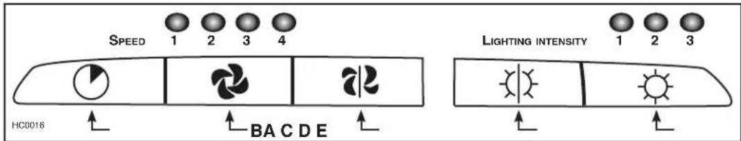
A. BLOWER DELAY-OFF BUTTON:
When blower is on, press the delay-off button to activate the delay-off function. The corresponding speed indicator LED will start flashing to indicate this function is activated. The fan will continue to operate for 10 minutes and will stop automatically. To cancel the delay-off function, press the blower delay-off button once again; the blower will then work in normal mode.
NOTE: The blower speed can be increased—or decreased—during delay-off mode without starting another 10-minute cycle.
B. ON BLOWER/SPEED CONTROL BUTTON:
Press this button to turn on the blower at the last selected speed. To change the blower speed, press the button again until the desired speed is obtained. Press and hold this button for 2 seconds to decrease the speed level down by one increment. Possible decreases are then: 4 to 3; 3 to 2; 2 to 1 and 1 to OFF.
NOTES: 1. Each time you press the speed control button, the speed changes by increments of 1 (e.g.: speed 1 to speed 2, to speed 3, and then speed 4). From the fourth speed, the speed goes down to level 1.
2. The last speed used is kept in memory so that when the unit is turned on, it will return to the last setting except the fourth, the next time the blower will be turned on, it will return to speed 3. The memorized speed level is also synced with the optional remote control.
HEAT SENTRY™
The power pack is equipped with a protective device that activates when excessive heat is detected inside the power pack. This device takes control of the blower and deactivates speed 4 for a 10-minute period and sets it on speed 3. During the Heat Sentry activation, only speed 3 can be used; the speed 4 button will flash while the speed 3 button will light up.
WARNING
The HEAT SENTRY can start the blower during a range top fire or other excessive heat situations even if the power pack is turned off. In this case, it is impossible to turn the blower OFF with blower button. If you must stop the blower, do it from the main electrical panel.
C. OFF BLOWER/FILTER MAINTENANCE BUTTON:
Press this button to turn off the blower. Pressing this button also cancels the delay-off function (if activated).
NOTE: After 25 hours of operation, the 4 blower speed lights will flash 30 seconds to indicate the filters need to be cleaned in order to maintain efficient power pack operation. Pressing the OFF button will reset the code to indicate that maintenance has been completed.
D. OFF LIGHTING:
Press this button to turn lights off.
E. ON LIGHT BUTTON:
Press this button to turn on the halogen lamps. The light intensity changes by increments of 1 (e.g.: Press once for low setting, once again for medium, again for high). From the higher setting, press once to go back to the lower setting.
NOTE: The last light setting used is kept in memory. The next time the halogen lamps are turned on, the last setting will be used. The memorized light setting is also synced with the optional remote control.
REMOTE CONTROL:
An optional ACR Series remote control (purchase separately) can be used to operate the power pack.
21. WARRANTY
FIVE-YEAR LIMITED WARRANTY FOR BEST® PRODUCTS
Warranty Period and Exclusions: Broan-NuTone, LLC (the "Company") warrants to the consumer purchaser of its product ("you") that the product (the "Product") will be free from material defects in the materials or its workmanship for a period of five (5) years from the date of original purchase (or such longer period as may be required by applicable law) or a period of two (2) years from the date of service for any labor provided on the Product.
The limited warranty period for any replacement parts provided by the Company and for any Products repaired or replaced under this limited warranty shall be the remainder of the original warranty period (or such longer period as may be required by applicable law).
THIS WARRANTY DOES NOT EXTEND TO FLUORESCENT LAMP STARTERS, TUBES AND BULBS, FUSES, FILTERS, DUCTS, ROOF CAPS, WALL CAPS AND OTHER ACCESSORIES FOR DUCTING. This warranty does not cover (a) normal maintenance and service, (b) normal wear and tear, (c) any Products or parts which have been subject to misuse, abuse, abnormal usage, negligence, accident, improper or insufficient maintenance, storage or repair (other than repair by the Company), (d) damage caused by faulty installation, or installation or use contrary to recommendations or instructions, (f) damage caused by exposure to salt air, (g) damage in transit, (h) natural wear of finish, (i) Products in commercial or nonresidential use, (j) damage caused by fire, flood or other act of God, or (k) Products with altered, defaced or removed serial numbers. This warranty covers only Products sold to consumers in North America. This warranty supersedes all prior warranties and, subject to applicable law, is not transferable from the original consumer purchaser.
No Other Warranties: This Limited Warranty contains the Company's sole obligation and your sole remedy for defective Products. The foregoing warranties are exclusive and in lieu of any other warranties and conditions, express or implied. TO THE MAXIMUM EXTENT PERMITTED BY APPLICABLE LAW, THE COMPANY DISCLAIMS AND EXCLUDES ALL OTHER EXPRESS WARRANTIES AND CONDITIONS, AND DISCLAIMS AND EXCLUDES ALL WARRANTIES AND CONDITIONS IMPLIED BY LAW, INCLUDING WITHOUT LIMITATION THOSE OF MERCHANTABILITY AND FITNESS FOR A PARTICULAR PURPOSE.
To the extent that applicable law prohibits the exclusion of implied warranties or conditions, the duration of any applicable implied warranty or condition is limited to the period specified for the express warranty above. Some jurisdictions (which may include the Province of Quebec or specific US states) do not allow limitations on how long an implied warranty lasts, so the above limitation may not apply to you. Any oral or written description of the Product is for the sole purpose of identifying it and shall not be construed as an express warranty.
Whenever possible, each provision of this Limited Warranty shall be interpreted in such manner as to be effective and valid under applicable law, but if any provision is held to be prohibited or invalid, such provision shall be ineffective only to the extent of such prohibition or invalidity, without invalidating the remainder of such provision or the other remaining provisions of the Limited Warranty.
Remedy: During the applicable limited warranty period, the Company will, at its option, provide replacement parts for, or repair or replace, without charge, any Product or part thereof, to the extent the Company finds it to be covered by and in breach of this limited warranty under normal use and service. The Company will ship the repaired or replaced Product or replacement parts to you at no charge. You are responsible for all costs for removal, reinstallation and shipping, insurance or other freight charges incurred in the shipment of the Product or part to the Company. If you must send the Product or part to the Company, as instructed by the Company, you must properly pack the Product or part—the Company is not responsible for damage in transit. The Company reserves the right to utilize reconditioned, refurbished, repaired or remanufactured Products or parts in the warranty repair or replacement process. Such Products and parts will be comparable in function and performance to an original Product or part and warranted for the remainder of the original warranty period (or such longer period as may be required by applicable law).
Company reserves the right, in its sole discretion, to refund the money actually paid by you for the Product. If the Product or component is no longer available, replacement may be made with a similar product of equal or greater value, at Company's sole discretion. This is your sole and exclusive remedy for breach of this limited warranty.
Exclusion of Damages: THE COMPANY'S OBLIGATION TO PROVIDE REPLACEMENT PARTS, OR REPAIR OR REPLACE, AT THE COMPANY'S OPTION, SHALL BE YOUR SOLE AND EXCLUSIVE REMEDY UNDER THIS LIMITED WARRANTY AND THE COMPANY'S SOLE AND EXCLUSIVE OBLIGATION. THE COMPANY SHALL NOT BE LIABLE FOR INCIDENTAL, INDIRECT, CONSEQUENTIAL OR SPECIAL DAMAGES ARISING OUT OF OR IN CONNECTION WITH THE PRODUCT, ITS USE OR PERFORMANCE.
Some jurisdictions do not allow the exclusion or limitation of incidental or consequential damages, so the above limitation or exclusion may not apply to you. This warranty gives you specific legal rights, and you may also have other rights, which vary from jurisdiction to jurisdiction. The disclaimers, exclusions, and limitations of liability under this warranty will not apply to the extent prohibited by applicable law.
This warranty covers only replacement or repair of defective Products or parts thereof at the Company's main facility and does not include the cost of field service travel and living expenses.
Any assistance the Company provides to or procures for you outside the terms, limitations or exclusions of this limited warranty will not constitute a waiver of such terms, limitations or exclusions, nor will such assistance extend or revive the warranty. The Company will not reimburse you for any expenses incurred by you in repairing or replacing any defective Product, except for those incurred with the Company's prior written permission.
How to Obtain Warranty Service: To qualify for warranty service, you must (a) notify the Company at the address or telephone number stated below within seven (7) days of discovering the covered defect, (b) give the model number and part identification and (c) describe the nature of any defect in the Product or part. At the time of requesting warranty service, you must present evidence of the original purchase date. If you cannot provide a copy of the original written limited warranty, then the terms of the Company's most current written limited warranty for your particular product will control.
PRODUCT SPECIFICATIONS
All illustrations and specifications in this catalog are based on the latest product information available at time of production. Broan-NuTone, LLC and BEST® reserves the right to make changes at any time, without notice, in prices, colors, materials, equipment, specifications and models, place of manufacture and to discontinue models or equipment.
Best
Broan-NuTone, LLC- 926 W. State Street, Hartford, WI 53207 1-800-637-1453
Best®, 550 Lemire Blvd., Drummondville, QC, Canada (1-866-737-7770) www.bestrangehoods.com
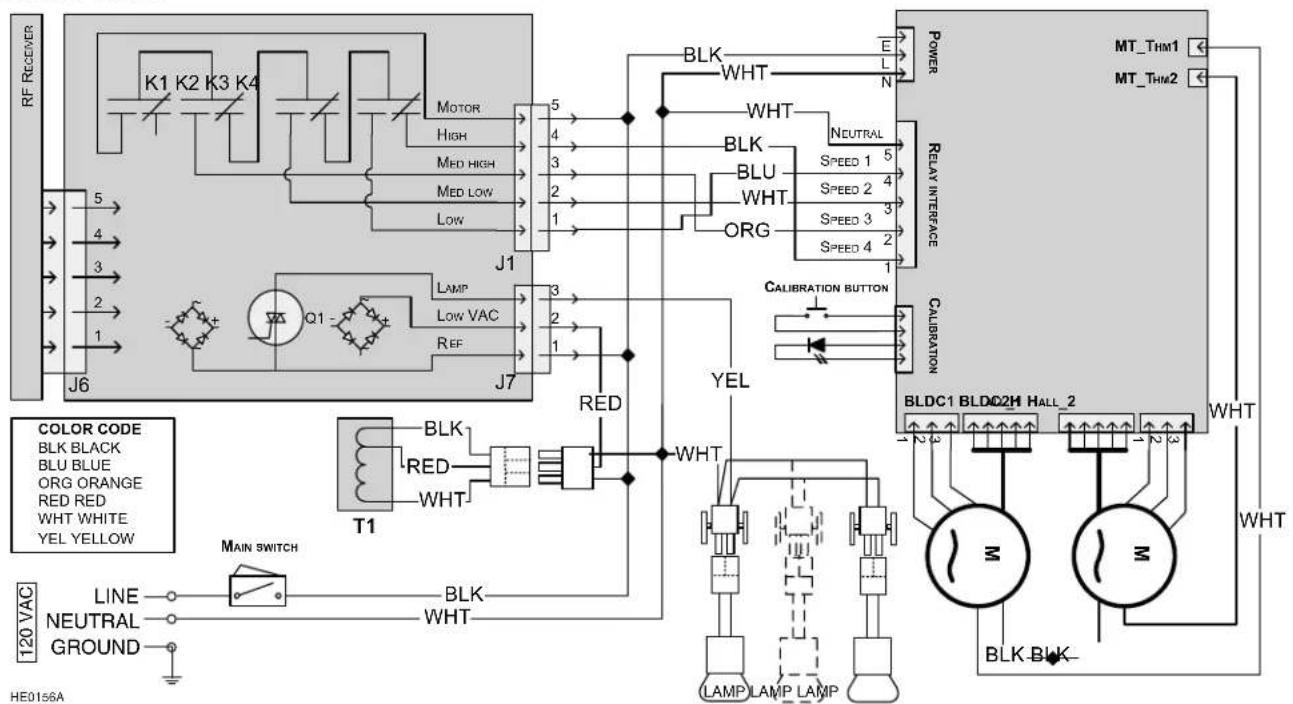
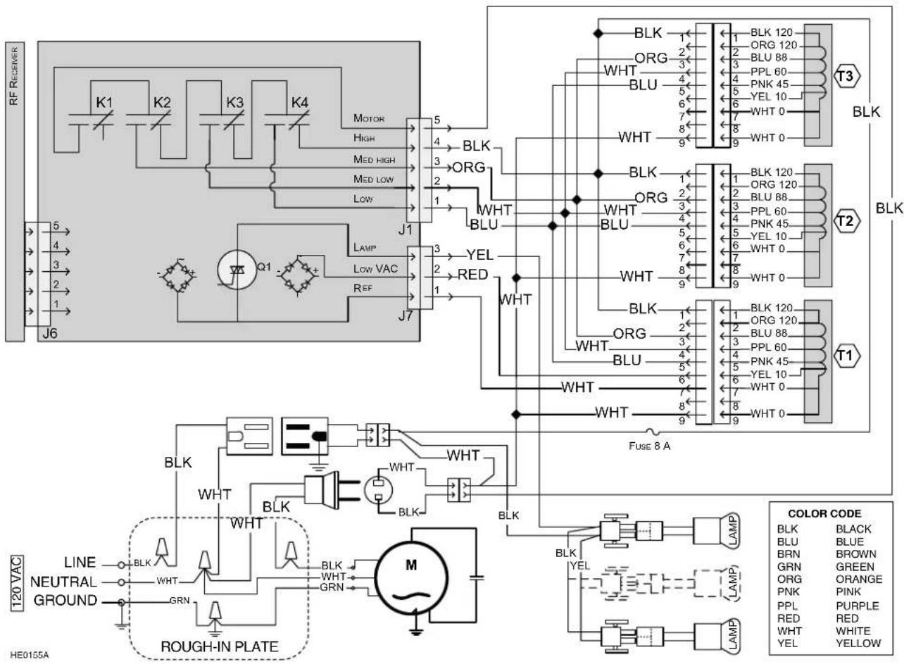
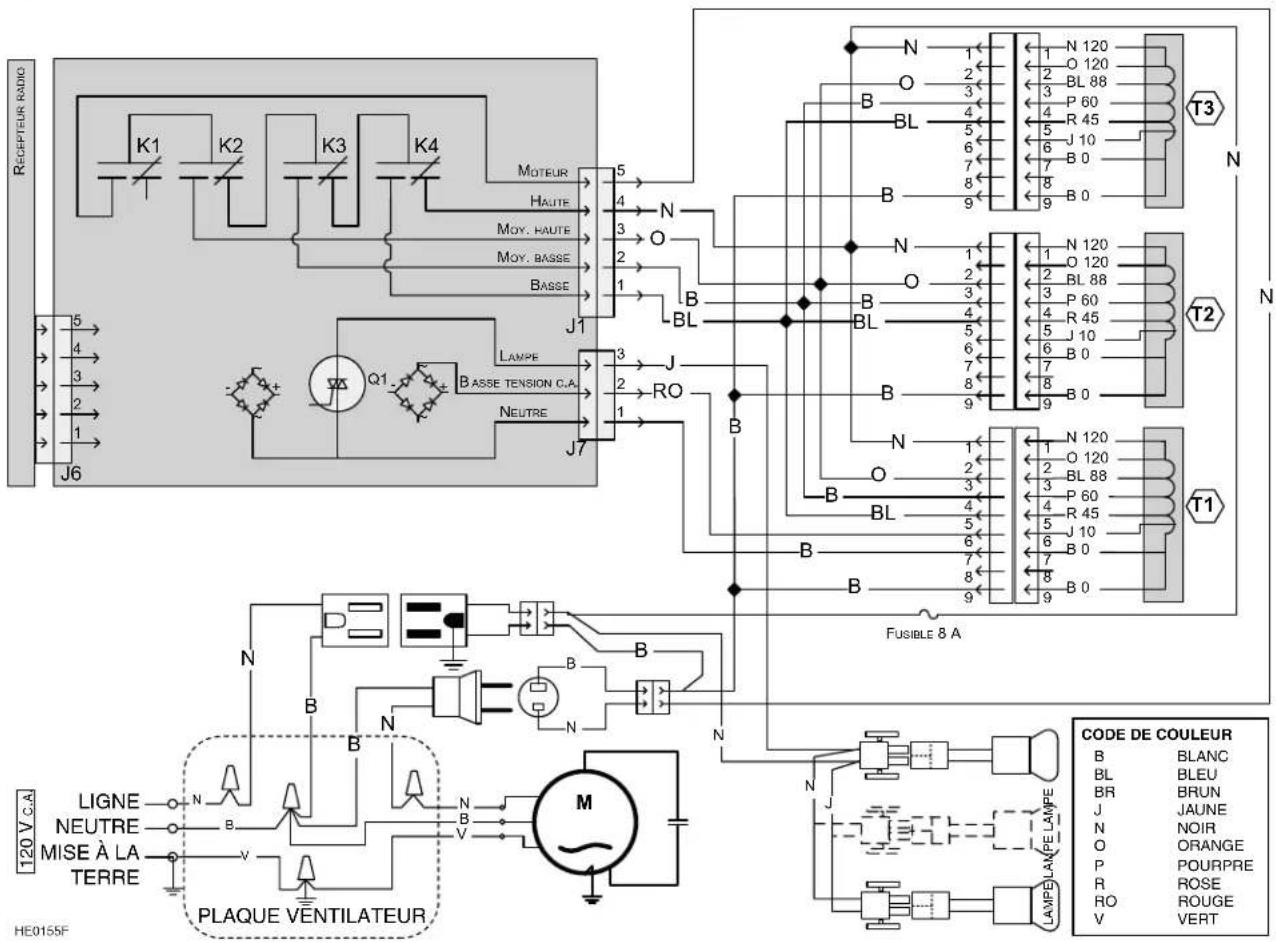
22. WIRING DIAGRAMS
Best PK22 series
flowchart
graph TD
    subgraph Power
        A["MT_THM1"] --> B["BLDC1"]
        C["MT_THM2"] --> D["BLDC2H"]
        B --> E["WHT"]
        D --> F["WHT"]
    end
    subgraph RelayInterface
        G["Relay Interface"] --> H["BLK"]
        G --> I["BLU"]
        G --> J["ORG"]
        G --> K["NEUTRAL"]
        G --> L["SPEED 1 5"]
        G --> M["SPEED 2 4"]
        G --> N["SPEED 3 3"]
        G --> O["SPEED 4 2"]
    end
    subgraph Calibration
        P["BLDC1"] --> Q["WHT"]
        R["BLDC2H"] --> S["WHT"]
    end
    subgraph Control
        T["MT_THM1"] --> U["BLK"]
        V["MT_THM2"] --> W["BLK"]
        X["BLK"] --> Y["WHT"]
    end
    subgraph Power
        Z["BLK"] --> AA["WHT"]
        AB["WHT"] --> AC["WHT"]
    end
    subgraph RelayInterface
        AD["BLK"] --> AE["WHT"]
        AF["WHT"] --> AG["WHT"]
    end
    subgraph Calibration
        AH["BLK"] --> AI["WHT"]
        AJ["WHT"] --> AK["WHT"]
    end
    subgraph Control
        AL["MT_THM1"] --> AM["BLK"]
        AN["MT_THM2"] --> AO["BLK"]
        AP["BLK"] --> AQ["WHT"]
    end
    subgraph Power
        AR["BLK"] --> AS["WHT"]
        AT["WHT"] --> AU["WHT"]
    end
    subgraph RelayInterface
        AV["BLK"] --> AW["WHT"]
        AX["WHT"] --> AY["WHT"]
    end
    subgraph Calibration
        AZ["BLK"] --> BA["WHT"]
        BB["WHT"] --> BC["WHT"]
    end
    subgraph Control
        BD["MT_THM1"] --> BE["BLK"]
        BF["MT_THM2"] --> BG["BLK"]
        BH["BLK"] --> BI["WHT"]
        BJ["WHT"] --> BK["WHT"]
    end
    subgraph Power
        BL["MT_THM1"] --> BM["BLK"]
        BN["MT_THM2"] --> BO["BLK"]
        BP["BLK"] --> BQ["WHT"]
        BR["WHT"] --> BS["WHT"]
    end
    subgraph RelayInterface
        BT["MT_THM1"] --> BU["BLK"]
        BV["MT_THM2"] --> BW["BLK"]
        BX["BLK"] --> BY["WHT"]
        BZ["WHT"] --> CA["WHT"]
    end
    subgraph Calibration
        CB["MT_THM1"] --> CC["BLK"]
        CD["MT_THM2"] --> CE["BLK"]
        CF["BLK"] --> CG["WHT"]
        CH["WHT"] --> CI["WHT"]
    end
Best PKEX22 series
Best PK22 Series
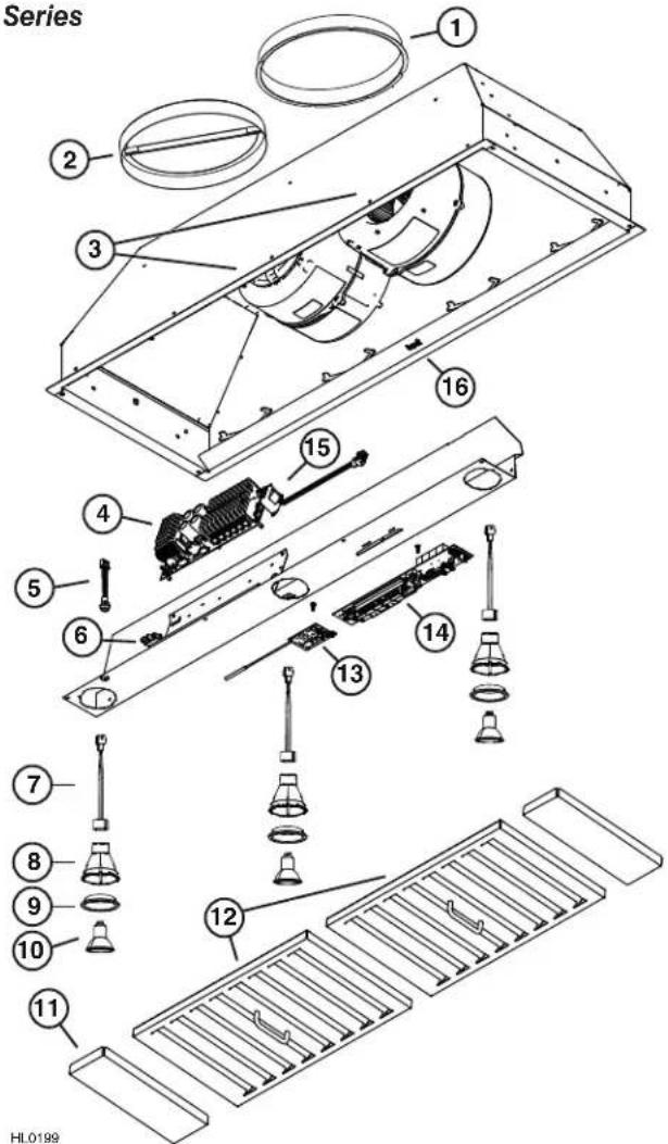
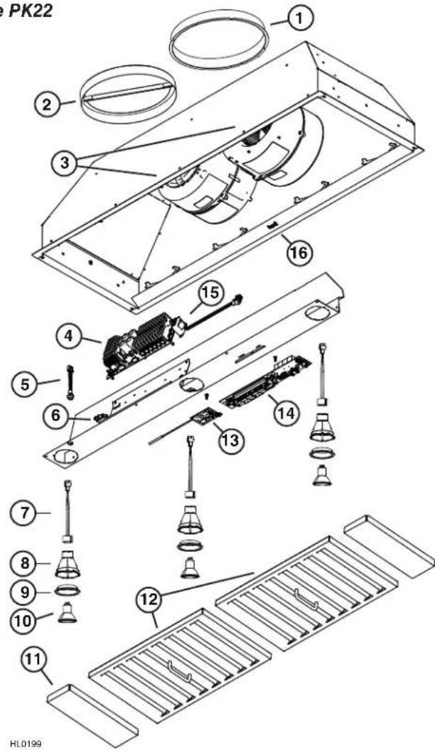
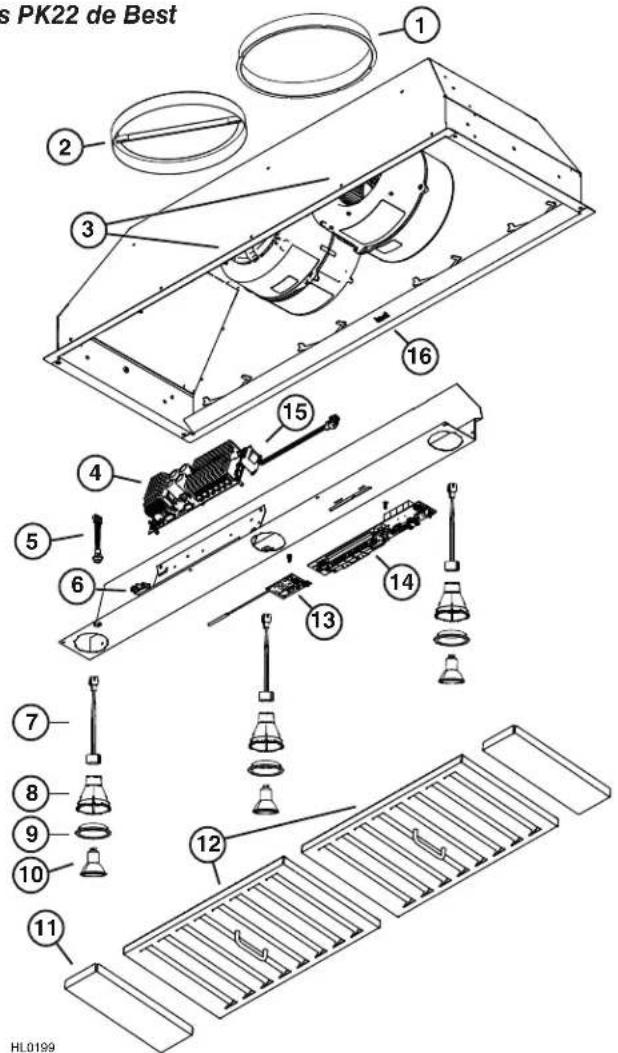
REPLACEMENT PARTS AND REPAIRS
In order to ensure your unit remains in good working condition, you must use Broan-NuTone genuine replacement parts only. Broan-NuTone genuine replacement parts are specially designed for each unit and are manufactured to comply with all the applicable certification standards and maintain a high standard of safety. Any third party replacement part used may cause serious damage and drastically reduce the performance level of your unit, which will result in premature failing. Broan-NuTone recommends to contact a certified service depot for all replacement parts and repairs.
| KEYNO. | PART NO. | DESCRIPTION | QTY. (POWER PACK WIDTH) | ||
| 30" 39" 45" | |||||
| 1 S | V08541 10" ROUND ADAPTER 1 | 1 1 | |||
| 2 S | V08542 10" ROUND DAMPER 1 | 1 1 | |||
| 3 S | 97018985 BLDC BLOWER, 600 CFM 2 2 2 | ||||
| 4 | SV20818 | ELECTRONIC DRIVE FOR DUAL BLDC BLOWER | 1 | 1 | 1 |
| 5 | SV20817 | CALIBRATION BUTTON | 1 | 1 | 1 |
| 6 S | V08548 B | LACK ROCKER SWITCH | 1 | 1 | 1 |
| 7 S | V05917 S | OCKET GU10 | 2 2 3 | ||
| 8 S | V09435 S | OCKET HOLDER GU10 | 2 2 3 | ||
| 9 S | V09434 L | IGHT TRIM STAINLESS STEEL | 2 | 2 | 3 |
| 10 | SV05921 H | ALOGEN BULB 120 V, 50 W, PAR16 WITH GU10 BASE | 2 | 2 | 3 |
| 11 | SV61044 | FILTER FILLER | 0 | 0 | 2 |
| 12 | SV61045 | BAFFLE FILTER WITH MICROMESH + HANDLE 12" x 10" | 2 | 0 | 0 |
| SV61046 | BAFFLE FILTER WITH MICROMESH + HANDLE 17" x 10" | 0 | 2 | 2 | |
| 13 | SV20816 | REMOTE CONTROL PCB | 1 | 1 | 1 |
| 14 | SV20814 | CONTROL INTERFACE PCB FOR INTERNAL BLOWER | 1 | 1 | 1 |
| 15 | SV09022 T | RANSFORMER 120 VAC, 9 VOLTS DC | 1 | 1 | 1 |
| 16 | SV05869 | BEST LOGO | 1 | 1 | 1 |
| * | SV20827 | INSTALLATION INSTRUCTIONS | 1 | 1 | 1 |
| * | SV20830 | PARTS BAG: 1 WIRE CLAMP, 2 WIRE CONNECTORS, 2 NO. 8 x 3/8" SCREWS, 6 NO. 8-18 x 1 14 " CHROME PLATED SCREWS. | 1 | 1 | 1 |
* Not shown.
Best PKEX22 Series
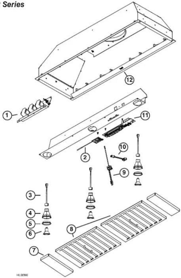
REPLACEMENT PARTS AND REPAIRS
In order to ensure your unit remains in good working condition, you must use Broan-NuTone genuine replacement parts only. Broan-NuTone genuine replacement parts are specially designed for each unit and are manufactured to comply with all the applicable certification standards and maintain a high standard of safety. Any third party replacement part used may cause serious damage and drastically reduce the performance level of your unit, which will result in premature failing. Broan-NuTone recommends to contact a certified service depot for all replacement parts and repairs.
| KEYNO. | PART NO. | DESCRIPTION | QTY. (POWER PACK WIDTH) | |
| 39" 45" | ||||
| 1 | SV61049 | AUTOTRANSFORMER AND FUSE KIT (INCLUDING METAL SUPPORT) | 1 | 1 |
| 2 | SV20816 | PCB FOR REMOTE CONTROL | 1 | 1 |
| 3 S | V05917 SOCKET GU10 2 3 | |||
| 4 S | V09435 SOCKET HOLDER GU10 2 3 | |||
| 5 | SV09434 | LIGHT TRIM STAINLESS STEEL | 2 | 3 |
| 6 S | V05921 H | ALOGEN BULB 120 V, 50 W, PAR16 WITH GU10 BASE | 2 | 3 |
| 7 | SV61044 | FILTER FILLER | 0 | 2 |
| 8 S | V61046 B | AFFLE FILTER WITH MICROMESH + HANDLE 17" x 10" | 2 | 2 |
| 9 S | V13924 M | ALE POWER CONNECTOR | 1 | 1 |
| 10 | SV13923 | FEMALE POWER CONNECTOR | 1 | 1 |
| 11 | SV20815 | CONTROL INTERFACE PCB FOR EXTERNAL BLOWER | 1 | 1 |
| 12 | SV05869 | BEST LOGO | 1 | 1 |
| * | SV20827 | INSTALLATION INSTRUCTIONS | 1 | 1 |
| * | SV20830 | PARTS BAG: 1 WIRE CLAMP, 2 WIRE CONNECTORS, 2 NO. 8 x 3/8" SCREWS, 6 NO. 8-18 x 1 14 " CHROME PLATED SCREWS. | 1 | 1 |
* Not shown.
best®
natural_image
3D rendering of a gray industrial ventilation duct with slatted ventilation slots and mounting holes (no text or symbols)SÉRIES PK22 ET PKEX22
⚠️CONÇUES POUR USAGE DOMESTIQUE SEULEMENT △
LIRE ET CONSERVER CES DIRECTIVES
INSTALLATEUR : LAISSER CE GUIDE AU PROPRIÉTAIRE. PROPRIÉTAIRE : DIRECTIVES D'UTILISATION ET D'ENTRETIEN EN PAGES 27 À 29.
BEST; Hartford, Wisconsin www.BestRangeHoods.com 800 558-1711 BEST; Drummondville, QC, Canada www.BestRangeHoods.ca 866 737-7770
natural_image
Technical line drawing of a mechanical enclosure or enclosure with ventilation grilles and a central cylindrical component (no text or symbols)7. RETIRER LE COUVERCLE DU COMPARTIMENT ÉLECTRIQUE (SÉRIE PK22 SEULEMENT)
natural_image
Technical line drawing of a mechanical component with two circular inset views (no text or symbols)9. INSTALLER L'ADAPTATEUR DE 10 PO (SÉRIE PK22 SEULEMENT)
11. INSTALLER LA PLAQUE VENTILATEUR POUR VENTILATEUR EXTERNE (SÉRIE PKEX22 SEULEMENT)
natural_image
Diagram of a mechanical or electrical component with labeled parts and a scale bar (no readable text or symbols)13. RACCORDER LES CONDUITS (TOUS LES MODÈLES)
natural_image
Close-up of two black electrical connectors labeled A and B, with wires extending outward (no text or symbols on the connectors themselves)16. RÉINSTALLER LES FILTRES À CHICANE HYBRIDES
ATTENTION
natural_image
Technical line drawing of a mechanical assembly with no visible text or symbols17. CALIBRER LE VENTILATEUR IQ ^MC (SÉRIE PK22 SEULEMENT)
SPÉCIFICATIONS DU PRODUIT
Broan-NuTone LLC : 926 W. State Street, Hartford (WI) 53207 1 800 637-1453
Best ^™ , 550, boul. Lemire, Drummondville (Québec), Canada (1 866 737-7770) fr.bestrangehoods.ca
22. SCHÉMAS ÉLECTRIQUES
Best série PK22
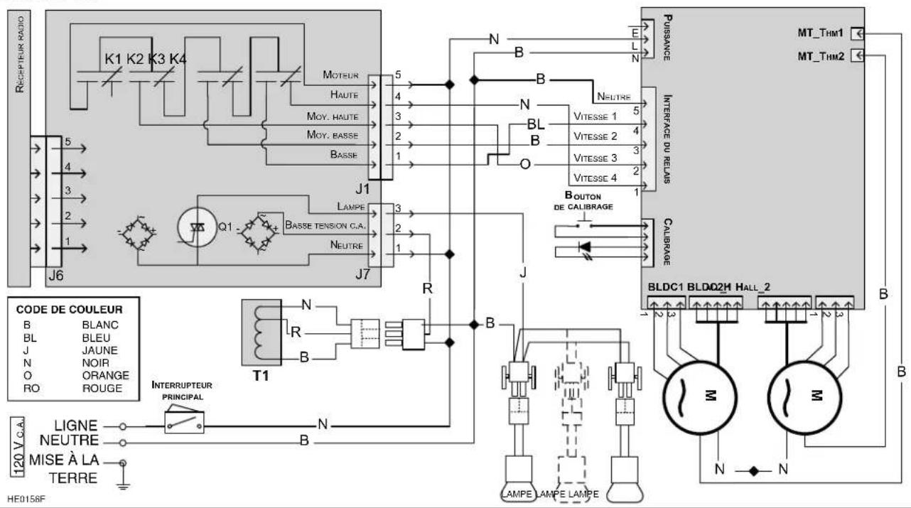
Best série PKEX22
23. PIÈCES DE REMPLACEMENT
Best série PK22
PIÈCES DE REMPLACEMENT ET SERVICE
PIÈCES DE REMPLACEMENT ET SERVICE
natural_image
3D rendering of a rectangular industrial enclosure with ventilation grilles and mounting holes (no text or symbols visible)SERIES PK22 Y PKEX22
⚠️ EXCLUSIVAMENTE PARA COCINAS DOMÉSTICAS △
LEA ESTAS INSTRUCCIONES Y GUÁRDELAS
INSTALADOR: ENTREGUE ESTE MANUAL AL PROPIETARIO DE LA CASA.
BEST; Drummondville, QC, Canada www.BestRangeHoods.ca 866-737-7770
www.BestRangeHoods.com
6. DESMONTAJE DE LOS FILTROS HÍBRIDOS
natural_image
Technical line drawing of a mechanical enclosure or enclosure with ventilation grilles and a central cylindrical component (no text or symbols)7. RETIRE LA TAPA DEL COMPARTIMENTO ELÉCTRICO (SERIE PK22 ÚNICAMENTE)
natural_image
Technical line drawing of a mechanical component with two circular inset views (no text or symbols)natural_image
Pure mechanical diagram showing gear and tubing without any text, numbers, or symbolsnatural_image
Close-up of two black electrical connectors labeled A and B, with wires attached (no text or symbols beyond labels)natural_image
Technical line drawing of a mechanical assembly with no visible text or symbolsBroan-NuTone, LLC: 926 W. State Street, Hartford, WI 53207 1 800 637-1453
Best®, 550, boul. Lemire, Drummondville (Québec), Canada (1 866 737-7770) www.bestrangehoods.com
22. DIAGRAMAS ELÉCTRICOS
Series PK22 de Best
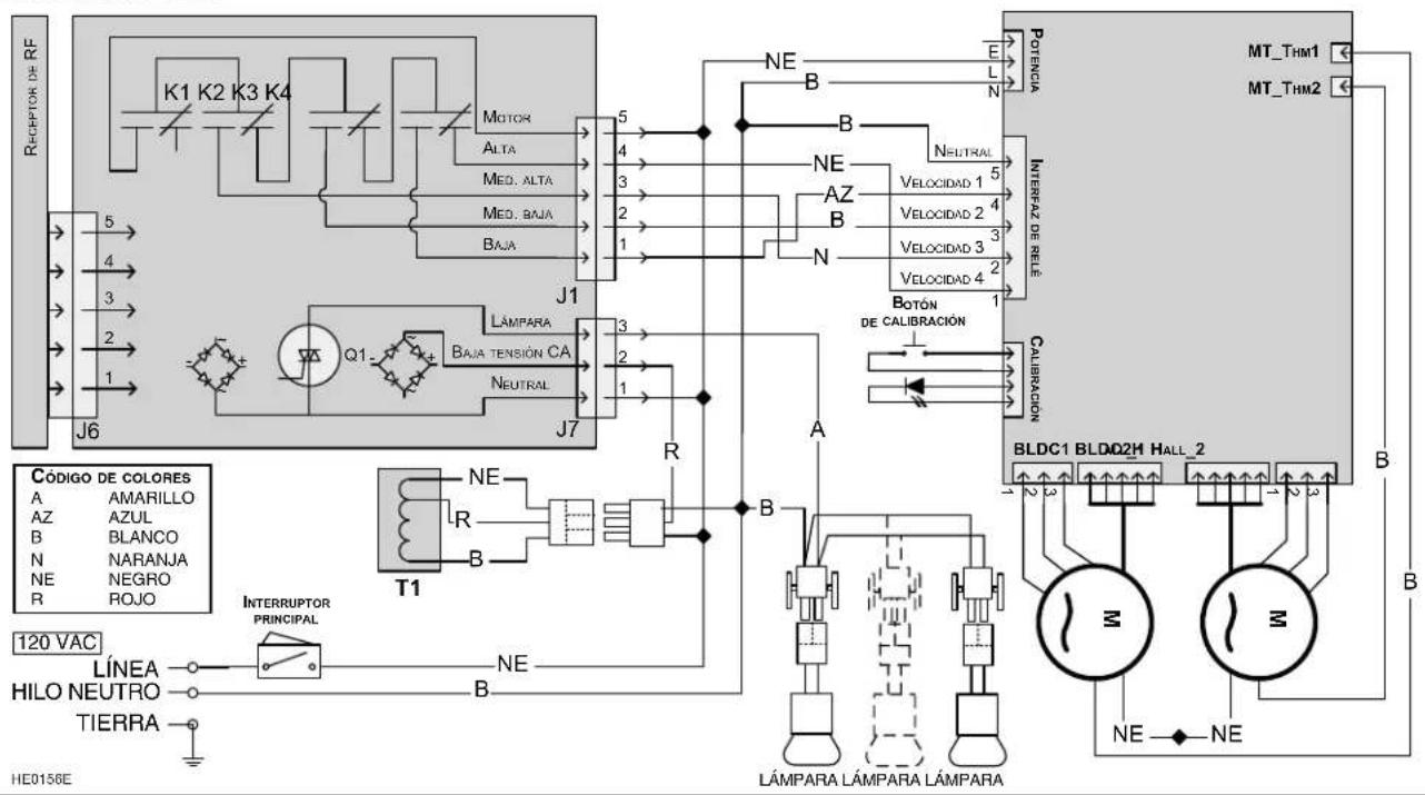
Series PKEX22 de Best
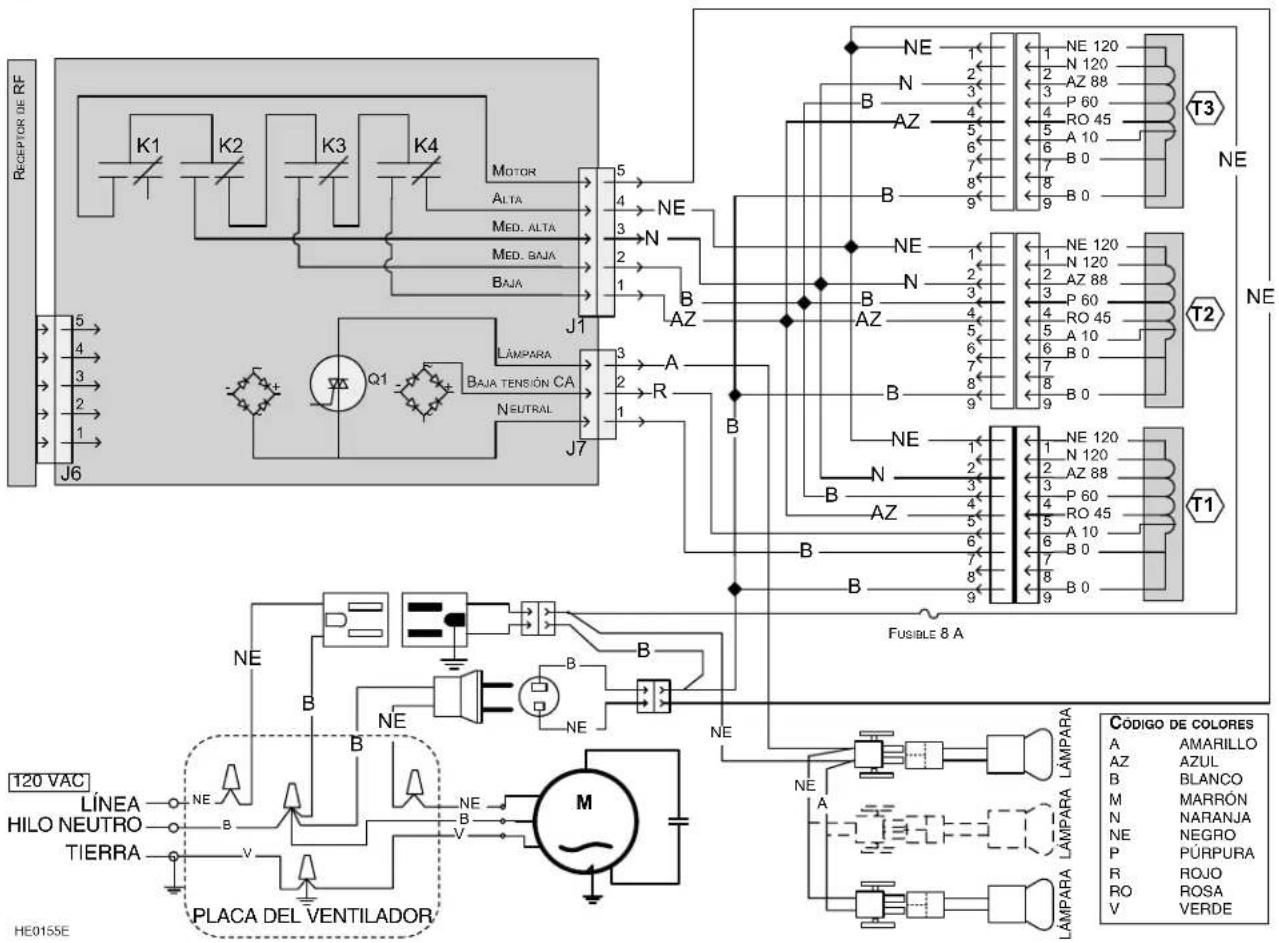
Series PK22 de Best

- PK22 AND PKEX22 SERIES
- READ AND SAVE THESE INSTRUCTIONS
- TO REDUCE THE RISK OF FIRE, ELECTRIC SHOCK OR INJURY TO PERSONS, OBSERVE THE FOLLOWING:
- TO REDUCE THE RISK OF A RANGE TOP GREASE FIRE:
- TO REDUCE THE RISK OF INJURY TO PERSONS IN THE EVENT OF A RANGE TOP GREASE FIRE, OBSERVE THE FOLLOWING\*:
- CAUTION
- PREPARE THE INSTALLATION
- WARNING
- PREPARE THE INSTALLATION (CONT'D)
- Parts sold separately:
- PREPARE CUSTOM HOOD
- INSTALL CUSTOM HOOD LINER (OPTIONAL)
- CUT HOLE IN CUSTOM HOOD BASE
- REMOVE HYBRID BAFFLE FILTERS
- REMOVE ELECTRICAL COMPARTMENT COVER (PK22 SERIES ONLY)
- INSTALL WIRE CLAMP (PK22 SERIES ONLY)
- INSTALL 10" ADAPTER (PK22 SERIES ONLY)
- INSTALL 10" DAMPER (PK22 SERIES ONLY)
- INSTALL ROUGH-IN PLATE FOR EXTERNAL BLOWER (PKEX22 SERIES ONLY)
- CONNECT WIRING (ALL MODELS)
- CONNECT DUCTING (ALL MODELS)
- INSTALL POWER PACK
- INSTALL BLOWER (PKEX22 SERIES ONLY)
- Do not plug the two cords together.
- REINSTALL HYBRID BAFFLE FILTERS
- CALIBRATE IQ BLOWER SYSTEM™ (PK22 SERIES ONLY)
- CALIBRATION PROCESS
- LIGHT BULBS
- USE AND CARE
- Hybrid Baffle Filters
- Internal Blowers Cleaning
- Power Pack Cleaning
- Avoid when choosing a detergent:
- OPERATION
- BLOWER DELAY-OFF BUTTON:
- ON BLOWER/SPEED CONTROL BUTTON:
- HEAT SENTRY™
- OFF BLOWER/FILTER MAINTENANCE BUTTON:
- OFF LIGHTING:
- ON LIGHT BUTTON:
- REMOTE CONTROL:
- WARRANTY
- FIVE-YEAR LIMITED WARRANTY FOR BEST® PRODUCTS
- PRODUCT SPECIFICATIONS
- WIRING DIAGRAMS
- REPLACEMENT PARTS AND REPAIRS
- best®
- SÉRIES PK22 ET PKEX22
- RETIRER LE COUVERCLE DU COMPARTIMENT ÉLECTRIQUE (SÉRIE PK22 SEULEMENT)
- INSTALLER L'ADAPTATEUR DE 10 PO (SÉRIE PK22 SEULEMENT)
- INSTALLER LA PLAQUE VENTILATEUR POUR VENTILATEUR EXTERNE (SÉRIE PKEX22 SEULEMENT)
- RACCORDER LES CONDUITS (TOUS LES MODÈLES)
- RÉINSTALLER LES FILTRES À CHICANE HYBRIDES
- ATTENTION
- CALIBRER LE VENTILATEUR IQ MC (SÉRIE PK22 SEULEMENT)
- SPÉCIFICATIONS DU PRODUIT
- SCHÉMAS ÉLECTRIQUES
- PIÈCES DE REMPLACEMENT
- PIÈCES DE REMPLACEMENT ET SERVICE
- SERIES PK22 Y PKEX22
- DESMONTAJE DE LOS FILTROS HÍBRIDOS
- RETIRE LA TAPA DEL COMPARTIMENTO ELÉCTRICO (SERIE PK22 ÚNICAMENTE)
- DIAGRAMAS ELÉCTRICOS
Brand : BEST
Model : PKEX2245
Category : Range hood