P195P2M70SB - Basket BEST - Free user manual and instructions
Find the device manual for free P195P2M70SB BEST in PDF.
Download the instructions for your Basket in PDF format for free! Find your manual P195P2M70SB - BEST and take your electronic device back in hand. On this page are published all the documents necessary for the use of your device. P195P2M70SB by BEST.
USER MANUAL P195P2M70SB BEST
READ AND SAVE THESE INSTRUCTIONS
WARNING TO REDUCE THE RISK OF FIRE, ELECTRIC SHOCK, OR INJURY TO PERSONS, OBSERVE THE FOLLOWING:
1. Use this unit only in the manner intended by the manufacturer. If you have questions,
contact the manufacturer at the address or telephone number listed in the warranty.
2. Before servicing or cleaning unit, switch power off at service panel and lock service
panel to prevent power from being switched on accidentally. When the service discon- necting means cannot be locked, securely fasten a prominent warning device, such as a tag, to the service panel.
3. Installation work and electrical wiring must be done by a qualifi ed person(s) in ac-
cordance with all applicable codes and standards, including fi re-rated construction codes and standards.
4. Suffi cient air is needed for proper combustion and exhausting of gases through the
fl ue (chimney) of fuel burning equipment to prevent backdrafting. Follow the heating equipment manufacturer’s guidelines and safety standards such as those published by the National Fire Protection Association (NFPA), and the American Society for Heating, Refrigeration and Air Conditioning Engineers (ASHRAE), and the local code authorities.
5. When cutting or drilling into wall or ceiling, do not damage electrical wiring and other
6. Ducted fans must always be vented to the outdoors.
7. Do not use this unit with any separate solid-state speed control device.
8. To reduce the risk of fi re, use only metal ductwork.
9. This unit must be grounded.
TO REDUCE THE RISK OF A RANGE TOP GREASE FIRE: A. Never leave surface units unattended at high settings. Boilovers cause smoking and greasy spillovers that may ignite. Heat oils slowly on low or medium settings. B. Always turn hood ON when cooking at high heat or when cooking fl aming foods. (i.e. Crepes Suzette, Cherries Jubilee, Peppercorn Beef Flambe’). C. Clean ventilating fans frequently. Grease should not be allowed to accumulate on fan or fi lter. D. Use proper pan size. Always use cookware appropriate for the size of the surface element. WARNING TO REDUCE THE RISK OF INJURY TO PERSONS IN THE EVENT OF A RANGE TOP
GREASE FIRE, OBSERVE THE FOLLOWING:*
1. SMOTHER FLAMES with a close-fi tting lid, cookie sheet, or metal tray, then turn off
the burner. BE CAREFUL TO PREVENT BURNS. If the fl ames do not go out im- mediately, EVACUATE AND CALL THE FIRE DEPARTMENT.
2. NEVER PICK UP A FLAMING PAN - You may be burned.
3. DO NOT USE WATER, including wet dishcloths or towels - violent steam explosion
A. You know you have a Class ABC extinguisher and you already know how to operate it. B. The fi re is small and contained in the area where it started. C. The fi re department is being called. D. You can fi ght the fi re with your back to an exit.
- Based on “Kitchen Fire Safety Tips” published by NFPA.
1. For indoor use only.
2. To reduce risk of fi re and to properly exhaust air, be sure to duct air outside. Do not
vent exhaust air into spaces within walls or ceilings or into attics, crawl spaces, or garages.
3. Take care when using cleaning agents or detergents.
4. Avoid using food products that produce fl ames under the Range Hood.
5. For general ventilating use only. Do not use to exhaust hazardous or explosive
materials and vapors.
6. To avoid motor bearing damage and noisy and/or unbalanced impellers, keep drywall
spray, construction dust, etc. off power unit.
7. Your hood motor has a thermal overload which will automatically shut off the motor
if it becomes overheated. The motor will restart when it cools down. If the motor continues to shut off and restart, have the hood serviced.
8. For best capture of cooking impurities, the bottom of the hood should be a minimum
of 24” and a maximum of 30” above the cooking surface.
9. This product is equipped with a thermostat which may start blower automatically. To
reduce the risk of injury and to prevent power from being switched on accidentally, switch power off at service panel and lock or tag service panel.
10. Use with approved cord-connection kit only.
11. Please read specifi cation label on product for further information and requirements.- 4 -
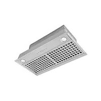
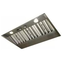
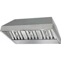
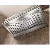
Unpack hood and check contents.
1 - Junction Box Cover
1 - 6” Damper Duct Connector
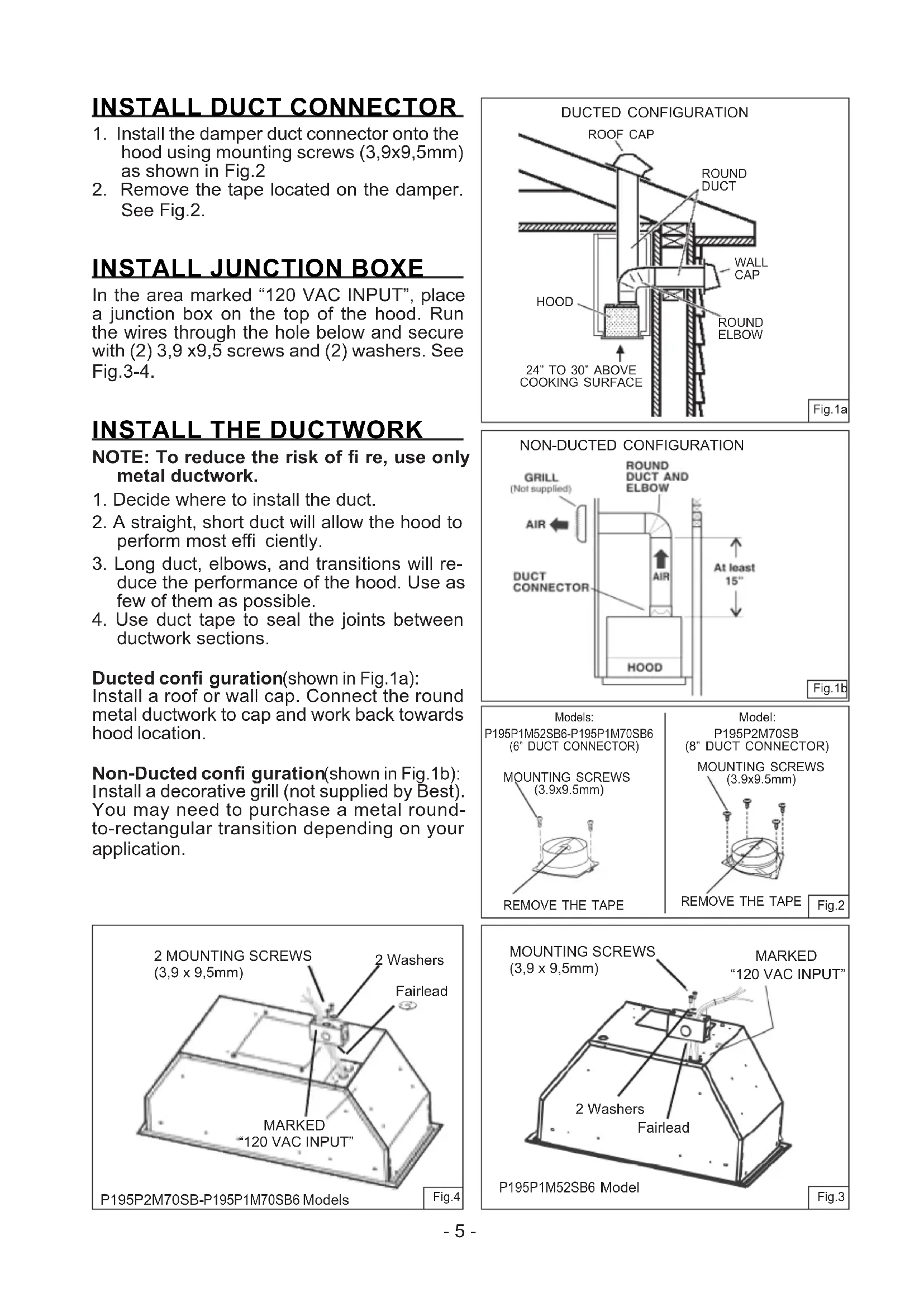
NOTE: To reduce the risk of fi re, use only metal ductwork.
1. Decide where to install the duct.
2. A straight, short duct will allow the hood to
perform most effi ciently.
3. Long duct, elbows, and transitions will re-
duce the performance of the hood. Use as few of them as possible.
4. Use duct tape to seal the joints between
ductwork sections. Ducted confi guration (shown in Fig.1a): Install a roof or wall cap. Connect the round metal ductwork to cap and work back towards hood location. Non-Ducted confi guration (shown in Fig.1b):
nstall a decorative grill (not supplied by Best). You may need to purchase a metal round- to-rectangular transition depending on your application. DUCTED CONFIGURATION ROOF CAP ROUND DUCT WALL CAP HOOD 24” TO 30” ABOVE COOKING SURFACE ROUND ELBOW
INSTALL JUNCTION BOXE
In the area marked “120 VAC INPUT”, place a junction box on the top of the hood. Run the wires through the hole below and secure with (2) 3,9 x9,5 screws and (2) washers. See Fig.3-4. MOUNTING SCREWS (3.9x9.5mm)
1. Install the damper duct connector onto the
hood using mounting screws (3,9x9,5mm) as shown in Fig.2
2. Remove the tape located on the damper.
See Fig.2. Fig.1a Fig.2 Fig.3 Fig.4 Fig.1b NON-DUCTED CONFIGURATION
1. Cut a hole in the bottom of the cabinet.
2. To install the hood, adjust the position of the
clasping side spring by turning the screws, according to the thickness of the cabinet to which it is going to be anchored. See Fig.6
3. Insert the hood in the cabinet and lock into
position using the side spring.
4. Use the holes in the hood, secure it with
MOUNTING SCREWS (4.2x20mm) Fig.5Fig.6Fig.7 WIRING Note: This range hood must be properly grounded. The unit should be installed by a qualifi ed electrician in accordance with all applicable national and local electrical codes.
- 120 VAC INPUT (FIG.8)
1. Secure the conduit to the wiring box through
a conduit connector.
2. Make electrical connections. Connect white
to white, black to black and green to green.
3. Install wiring box cover and secure it with (2)
screws 3,9 x 6 mm and (2) washers. Make sure that wires are not pinched between cover and box.
NECTION (FIG.9) The hood is compatible with Broan Make-Up Air Damper Model MD6T or Model MD8T (op- tional). Purchase separately. Make the connection to the Make-Up Air Damper with low voltage wiring, as shown. See Make-Up Air Damper instructions for additional information. WIRING BOX COVER(2) SCREWS(3,9 x 6mm)2 WASHERS MAKE-UP AIR DAMPER CONNECTION 120 VAC INPUT Fig.8Fig.92 Mounting screws on each side (as shown)Dimension from bottom edge of cabinet to center line of screw/hole 0,3”- 0,4”
1. Use 6”or 8” round metal duct to connect
the duct connector on the hood to the duc- twork above.
2. Use duct tape to make all joints secure and
air tight. For model P195P1M52SB6For models P195P1M70SB6 P195P2M70SB- 7 - MAINTENANCE Grease Filters The grease fi lter/s should be cleaned frequent- ly. Use a warm detergent solution. Grease fi lters are dishwasher safe. To take off the grease fi lter/s fi rst open the closure panel pulling downwards. See Fig.10 To take off the grease fi lter/s: at the handle, push the stop inwards and pull the filters downwards. See Fig.11. Hood Cleaning Stainless steel is one of the easiest materials to keep clean. Occasional care will help preserve its fi ne appearance. Cleaning tips: l Hot water with soap or detergent is all that is usually needed. l Rinse water. Wipe dry with a clean, soft cloth to avoid water marks. l For discolorations or deposits, use a non- scratching household cleanser or stainless steel polish with a soft cloth. l For stubborn cases, use a plastic scour- ing pad or soft bristle brush together with cleaser and water. Rub lightly in direction of the “grain” of the stainless fi nish. Avoid using too much pressure which may mar the surface. l DO NOT allow deposits to remain for long periods of time. l DO NOT use ordinary steel wool or steel brushes. Small bits of steel may adhere to the surface causing rust. l DO NOT allow salt solutions, disinfectants, bleaches, or cleaning compounds to remain in contact with stainless steel for extended periods. Many of these compounds contain chemicals which may be harmful. Rinse with water after exposure and wipe dry with a clean cloth. Painted surfaces should be cleaned with warm water and mild detergent only. CLOSURE PANEL
Fig.10 Fig.11 INSTALL RECIRCULATION KIT (Non-Duct Option Only) Purchase Charcoal Filter Kit Model AF- CP195P52 for P195P1M52 or AFCP195P70 for P195PM70. Replace fi lters every 3 months.- 8 - OPERATION The hood is operated using the (5) push buttons located on the front edge of the hood. The Light Off switch turns the lights off and on. The Light Intensity switch increases and decreases the lighting level. The Blower Off /Speed switch turns the blower off and changes blower speed to four diff erent speed settings: high, medium-high, medium-low and low speed. Depress and hold the button for 2 seconds to turn the blower off . The Blower On/Speed switch turns the blower on to four diff erent speed settings: Low, medium-low, medium-high and high speed. The LED Display:
- Indicates blower speed selection from 1 (lowspeed) to 4 (high speed).
- Flashes the blower speed when the 10-minute delay off has been activated.
- After 30 hours of operation, the center segment of the display blinks and remains lit, indicating that the fi lter needs to be cleaned. The Delay off feature: When pushed, the blower will continue to operate at the current speed setting for 10 minutes before automatically turning itself off . The Filter Alarm Reset switch is used to reset the 30-hour fi lter timer. After the fi lter is cleaned or replaced, press this switch once to reset the fi lter clean alarm. Light OFF Light Intensity Blower Off /Speed LED Display Delay off / Filter Alarm Reset Blower On/Speed HEAT SENTRY™ Your hood is equipped with a HEAT SENTRY™ thermostat. This thermostat is a device that will turn on or speed up the blower if it senses excessive heat above the cooking surface.
1) If blower is OFF - it turns blower ON to HIGH speed.
2) If blower is ON at a lower speed setting - it turns blower up to HIGH speed.
When the temperature level drops to normal, the blower will return to its original setting. WARNING The HEAT SENTRY thermostat can start the blower even if the hood is turned OFF. When this occurs, it is impossible to turn the blower OFF with its switch. If you must stop the blower, do it from the main electrical panel. REMOTE CONTROL: An optional ACR Series remote control (purchase separately) can be used to operated the power pack.- 9 - HALOGEN SPOTLIGHT This range hood requires two halogen bulbs (Type T3, 12Volt, 20Watt Max, G-4 Base).
WARNING: Always switch off the
electricity supply before carrying out any operations on the appliance.
1. Open the cover by prying from the
proper slots. See Fig. 12.
2. Remove the bulb by pulling sideways.
(DO NOT ROTATE) CAUTION: Bulb may be hot.
3. Replace with Type T3, 12Volt, 20Watt
Max, G-4 Base halogen bulb. Do not touch replacement bulb with bare hands!
Fig.12- 10 - Limited Warranty Warranty Period and Exclusions: Broan-NuTone, LLC(the “Company”) warrants to the consumer purchaser of its product (“you”) that the product (the “Product”) will be free from material defects in the materials or its workmanship for a period of fi ve (5) years from the date of original purchase (or such longer period as may be required by applicable law) or a period of two (2) years from the date of service for any labor provided on the Product. The limited warranty period for any replacement parts provided by the Company and for any Products repaired or replaced under this limited warranty shall be the remainder of the original warranty period (or such longer period as may be required by applicable law). THIS WARRANTY DOES NOT EXTEND TO FLUORESCENT LAMP STARTERS, TUBES AND BULBS, FUSES, FILTERS, DUCTS, ROOF CAPS, WALL CAPS AND OTHER ACCESSORIES FOR DUCTING. This warranty does not cover (a) normal maintenance and service, (b) normal wear and tear, (c) any Products or parts which have been subject to misuse, abuse, abnormal usage, negligence, accident, improper or insuffi cient maintenance, storage or repair (other than repair by the Company), (d) damage caused by faulty installation, or installation or use contrary to recommendations or instructions, (f) damage caused by exposure to salt air, (g) damage in transit, (h) natural wear of fi nish, (i) Products in commercial or nonresidential use, (j) damage caused by fi re, fl ood or other act of God, or (k) Products with altered, defaced or removed serial numbers. This warranty covers only Products sold to consumers in North America. This warranty supersedes all prior warranties and, subject to applicable law, is not transferable from the original consumer purchaser. No Other Warranties: This Limited Warranty contains the Company’s sole obligation and your sole remedy for defective Products. The foregoing warranties are exclusive and in lieu of any other warranties and conditions, express or implied. TO THE MAXIMUM EXTENT PERMITTED BY APPLICABLE LAW, THE COMPANY DISCLAIMS AND EXCLUDES ALL OTHER EXPRESS WARRANTIES AND CONDI- TIONS, AND DISCLAIMS AND EXCLUDES ALL WARRANTIES AND CONDITIONS IMPLIED BY LAW, INCLUDING WITHOUT LIMITATION THOSE OF MERCHANTABILITY AND FITNESS FOR A PARTICULAR PURPOSE. To the extent that applicable law prohibits the exclusion of implied warranties or conditions, the duration of any applicable implied warranty or condition is limited to the period specifi ed for the express warranty above. Some jurisdictions (which may include the Province of Quebec or specifi c US states) do not allow limitations on how long an implied warranty lasts, so the above limitation may not apply to you. Any oral or written description of the Product is for the sole purpose of identifying it and shall not be construed as an express warranty. Whenever possible, each provision of this Limited Warranty shall be interpreted in such manner as to be eff ective and valid under applicable law, but if any provision is held to be prohibited or invalid, such provision shall be ineff ective only to the extent of such prohibition or invalidity, without invalidating the remainder of such provision or the other remaining provisions of the Limited Warranty. Remedy: During the applicable limited warranty period, the Company will, at its option, provide replacement parts for, or repair or replace, without charge, any Product or part thereof, to the extent the Company fi nds it to be covered by and in breach of this limited warranty under normal use and service. The Company will ship the repaired or replaced Product or replacement parts to you at no charge. You are responsible for all costs for removal, reinstallation and shipping, insurance or other freight charges incurred in the shipment of the Product or part to the Company. If you must send the Product or part to the Company, as instructed by the Company, you must properly pack the Product or part—the Company is not responsible for damage in transit. The Company reserves the right to utilize reconditioned, refurbished, repaired or remanufactured Products or parts in the warranty repair or replacement process. Such Products and parts will be comparable in function and performance to an original Product or part and warranted for the remainder of the original warranty period (or such longer period as may be required by applicable law). Company reserves the right, in its sole discretion, to refund the money actually paid by you for the Product. If the Product or component is no longer available, replacement may be made with a similar product of equal or greater value, at Company’s sole discretion. This is your sole and exclusive remedy for breach of this limited warranty. Exclusion of Damages: THE COMPANY’S OBLIGATION TO PROVIDE REPLACEMENT PARTS, OR REPAIR OR REPLACE, AT THE COMPANY’S OPTION, SHALL BE YOUR SOLE AND EXCLUSIVE REMEDY UNDER THIS LIMITED WARRANTY AND THE COMPANY’S SOLE AND EXCLUSIVE OBLIGATION. THE COMPANY SHALL NOT BE LIABLE FOR INCIDENTAL, INDIRECT, CONSEQUENTIAL OR SPECIAL DAMAGES ARISING OUT OF OR IN CONNECTION WITH THE PRODUCT, ITS USE OR PERFORMANCE. Some jurisdictions do not allow the exclusion or limitation of incidental or consequential damages, so the above limitation or exclusion may not apply to you. This warranty gives you specifi c legal rights, and you may also have other rights, which vary from jurisdiction to jurisdic- tion. The disclaimers, exclusions, and limitations of liability under this warranty will not apply to the extent prohibited by applicable law. This warranty covers only replacement or repair of defective Products or parts thereof at the Company’s main facility and does not include the cost of fi eld service travel and living expenses. Any assistance the Company provides to or procures for you outside the terms, limitations or exclusions of this limited warranty will not constitute a waiver of such terms, limitations or exclusions, nor will such assistance extend or revive the warranty. The Company will not reimburse you for any expenses incurred by you in repairing or replacing any defective Product, except for those incurred with the Company’s prior written permission. How to Obtain Warranty Service: To qualify for warranty service, you must (a) notify the Company at the address or telephone number stated below within seven (7) days of discovering the covered defect, (b) give the model number and part identifi cation and (c) describe the nature of any defect in the Product or part. At the time of requesting warranty service, you must present evidence of the original purchase date. If you cannot provide a copy of the original written limited warranty, then the terms of the Company’s most current written limited warranty for your particular product will control. PRODUCT SPECIFICATIONS All illustrations and specifi cations in this catalog are based on the latest product information available at time of production. Broan-NuTone, LLC and BEST® reserves the right to make changes at any time, without notice, in prices, colors, materials, equipment, specifi cations and models, place of manufacture and to discontinue models or equipment. Best Broan-NuTone, LLC- 926 W. State Street, Hartford, WI 53207 1-800-637-1453 Best®, 550 Lemire Blvd., Drummondville, QC, Canada (1-866-737-7770) www.bestrangehoods.com- 11 - SERVICE PARTS B003100148 B003100147 B02011013 B08087694 B08087527 B02300804 B08093332 BE3350233 BE3334252 B03295008 BE3405682 BE3405683 B02011422 B02300806 B02011376 B02301058 B02320371 B08084041 B080814410 B06102757 B06102773 B06102756 B080814051 B080810849 B06002309U FRAME - ONLY FOR P195P1M52 MODEL FRAME - ONLY FOR P195PM70 MODEL SPRING GREASE FILTER -