CPDI362SB - Basket BEST - Free user manual and instructions
Find the device manual for free CPDI362SB BEST in PDF.

User questions about CPDI362SB BEST
0 question about this device. Answer the ones you know or ask your own.
Ask a new question about this device
Download the instructions for your Basket in PDF format for free! Find your manual CPDI362SB - BEST and take your electronic device back in hand. On this page are published all the documents necessary for the use of your device. CPDI362SB by BEST.
USER MANUAL CPDI362SB BEST
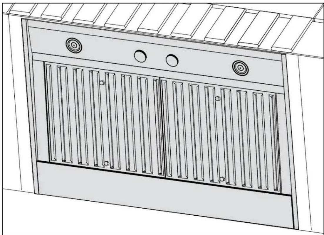
natural_image
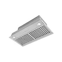
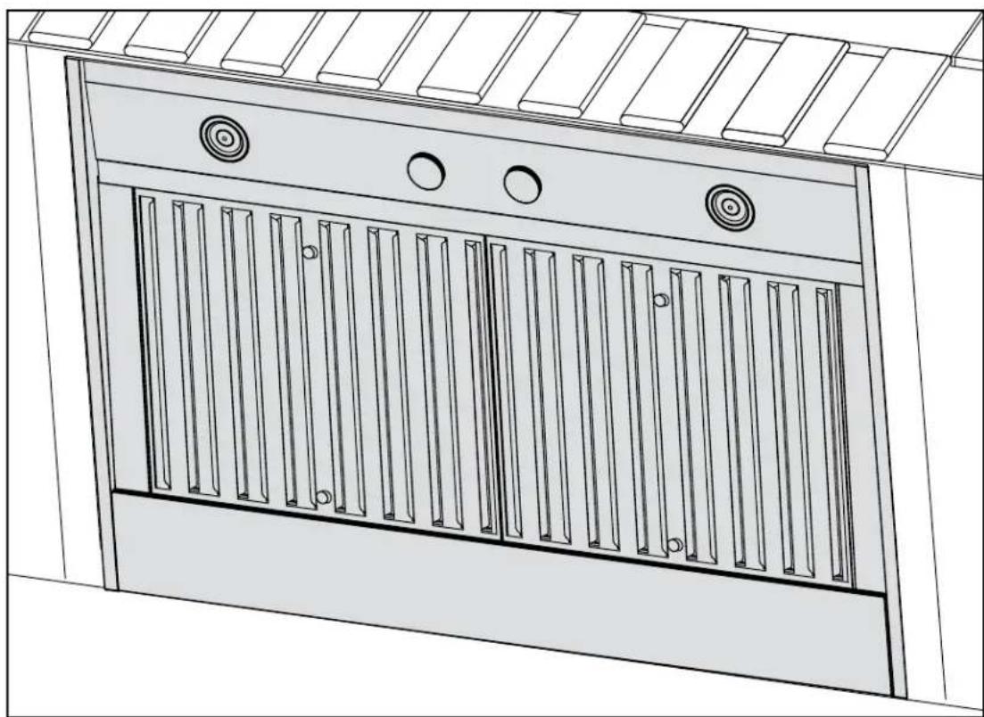
Technical line drawing of a cabinet or enclosure with vertical slats and circular components (no text or symbols)CPD SERIES
Suitable for use in damp locations when installed in a GFCI protected branch circuit. Intended for outdoor covered patio or lanai area.
⚠ INTENDED FOR DOMESTIC COOKING ONLY⚠
READ AND SAVE THESE INSTRUCTIONS
INSTALLER: LEAVE THIS MANUAL WITH HOMEOWNER. HOMEOWNER: USE AND CARE INFORMATION ON PAGES 12 to 13.
BEST®; Hartford, Wisconsin www.BestRangeHoods.com 800-637-1453
BEST®; Drummondville, QC, Canada www.BestRangeHoods.com 866-737-7770
REGISTER YOUR PRODUCT ON LINE AT: www.BestRangeHoods.com/register
For additional information - visit www.BestRangeHoods.com

WARNING WARNING
TO REDUCE THE RISK OF FIRE, ELECTRIC SHOCK OR INJURY TO PERSONS, OBSERVE THE FOLLOWING:
- Use this unit only in the manner intended by the manufacturer. If you have questions, contact the manufacturer at the address or telephone number listed in the warranty.
- Before servicing or cleaning unit, switch power off at service panel and lock service disconnecting means to prevent power from being switched on accidentally. When the service disconnecting means cannot be locked, securely fasten a prominent warning device, such as a tag, to the service panel.
- Installation work and electrical wiring must be done by qualified personnel in accordance with all applicable codes and standards, including fire-rated construction codes and standards.
- Sufficient air is needed for proper combustion and exhausting of gases through the flue (chimney) of fuel burning equipment to prevent backdrafting. Follow the heating equipment manufacturer's guidelines and safety standards such as those published by the National Fire Protection Association (NFPA) and the American Society for Heating, Refrigeration and Air Conditioning Engineers (ASHRAE) and the local code authorities.
- When cutting or drilling into wall or ceiling, do not damage electrical wiring and other hidden utilities.
- Ducted fans must always be vented to the outdoors.
- Do not use this unit with any solid-state speed control device.
- To reduce the risk of fire, use only metal ductwork.
- This unit is not designed for use with a charcoal grille.
- This unit must be grounded and protected by a GFCI (Ground Fault Circuit Interrupter).
- When applicable local regulations comprise more restrictive installation and/or certification requirements, the aforementioned requirements prevail on those of this document and the installer agrees to conform to these at his own expenses.
- Suitable for use in damp locations only when installed in a GFCI protected branch circuit.
TO REDUCE THE RISK OF A RANGE TOP GREASE FIRE:
a) Never leave surface units unattended at high settings. Boilovers cause smoking and greasy spillovers that may ignite. Heat oils slowly on low or medium settings.
b) Always turn power pack ON when cooking at high heat or when flambeing food (i.e.: Crêpes Suzette, Cherries Jubilee, Peppercorn Beef Flambé).
c) Clean ventilating fans frequently. Grease should not be allowed to accumulate on fan, filters or in exhaust ducts.
d) Use proper pan size. Always use cookware appropriate for the size of the surface element.

TO REDUCE THE RISK OF INJURY TO PERSONS IN THE EVENT OF A RANGE TOP GREASE FIRE, OBSERVE THE FOLLOWING\*:
- SMOTHER FLAMES with a close-fitting lid, cookie sheet or metal tray, then turn off the burner. BE CAREFUL TO PREVENT BURNS. IF THE FLAMES DO NOT GO OUT IMMEDIATELY, EVACUATE AND CALL THE FIRE DEPARTMENT.
- NEVER PICK UP A FLAMING PAN — You may be burned.
- DO NOT USE WATER, including wet dishcloths or towels — This could cause a violent steam explosion.
- Use an extinguisher ONLY if:
A. You own a Class ABC extinguisher and you know how to operate it.
B. The fire is small and contained in the area where it started.
C. The fire department has been called.
D. You can fight the fire with your back to an exit.
* Based on "Kitchen Fire Safety Tips" published by NFPA.
CAUTION
- For general ventilating use only. Do not use to exhaust hazardous or explosive materials and vapors.
- To avoid motor bearing damage and noisy and/or unbalanced impellers, keep drywall spray, construction dust, etc. off power unit.
- Your insert motor has a thermal overload which will automatically shut off the motor if it becomes overheated. The motor will restart when it cools down. If the motor continues to shut off and restart, have the power pack serviced.
- The minimum power pack distance above cooktop must not be less than 36".
- Two installers are recommended because of the large size and weight of this unit.
- To reduce the risk of fire and to properly exhaust air, be sure to duct air outside — Do not exhaust air into spaces within walls or ceiling or into attics, crawl space or garage.
- This product is equipped with a thermostat which may start blower automatically. To reduce the risk of injury and to prevent power from being switched on accidentally, switch power off at service panel and lock or tag service panel.
- Because of the high exhausting capacity of this unit, you should make sure enough air is entering the house to replace exhausted air by opening a window close to or in the kitchen.
- To reduce the risk of fire and electrical shock, the Best models CPD Series should only be installed with built-in blowers. Other blowers cannot be substituted.
- Please read specification label on product for further information and requirements.
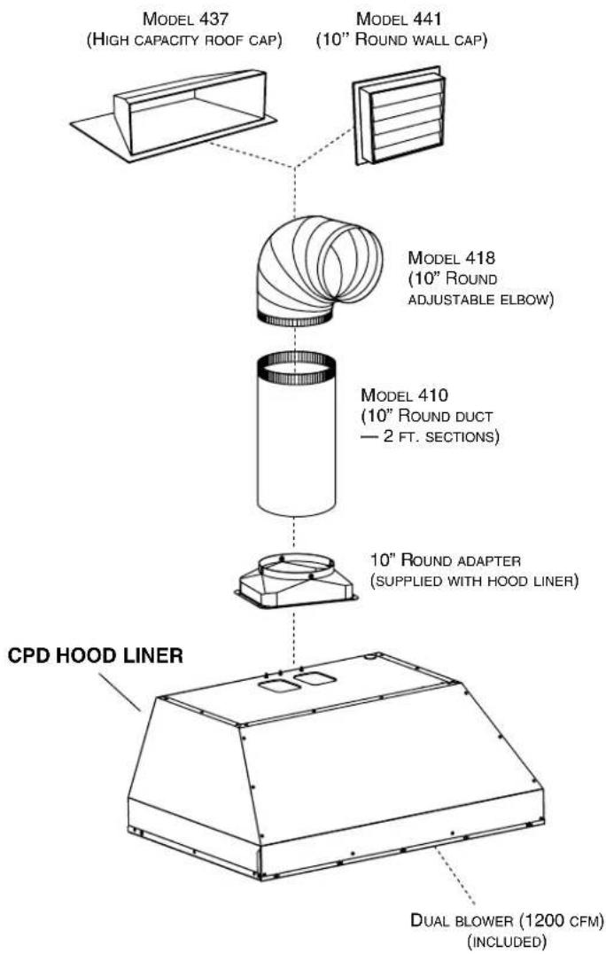
- CPD HOOD LINER SYSTEM -
text_image
MODEL 437 (HIGH CAPACITY ROOF CAP) MODEL 441 (10" ROUND WALL CAP) MODEL 418 (10" ROUND ADJUSTABLE ELBOW) MODEL 410 (10" ROUND DUCT — 2 FT. SECTIONS) 10" ROUND ADAPTER (SUPPLIED WITH HOOD LINER) CPD HOOD LINER DUAL BLOWER (1200 CFM) (INCULDED)1. INSTALL DUCTWORK AND ELECTRICAL WIRING
INSTALLATION
Install proper-sized ductwork, elbows and roof or wall cap for the type of blower you are installing. Use 10" round ductwork. Use metal foil duct tape to seal duct joints.
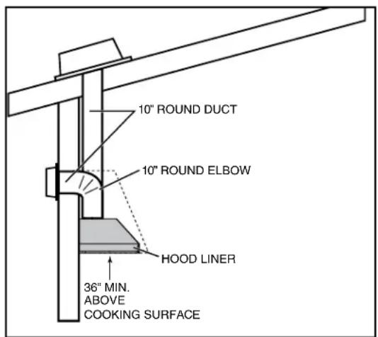
The minimum hood liner distance above cooktop must not be less than 36".
Distances over 36" are at the installer and users discretion.
Run 3-wire power supply cable to installation location. Its length should extend at least 4 feet below the bottom of the custom hood.
text_image
10" ROUND DUCT 10" ROUND ELBOW HOOD LINER 36" MIN. ABOVE COOKING SURFACECPD (DUAL INTERNAL BLOWER) TYPICAL DUCTWORK
2. PREPARE THE INSTALLATION
WARNING
When performing installation, servicing or cleaning the unit, it is recommended to wear safety glasses and gloves.
NOTE: Before proceeding to the installation, check the contents of the box. If items are missing or damaged, contact the manufacturer. Make sure that the following items are included:
- Hood Liner
-Accessories:
- Baffle filters (2 for 36" width, 3 for 48" and 60" widths)
- Shielded halogen lamps (120 V, 50 W, MR16 with GU10 base or PAR16 with GU10 base) (2 for CPDI362, 4 for all other models)
• 10" round adapter
- Bag of parts including: 12 - #8 x 12 " flat head screws (16 - for CPDI602), 4 - M4 x 6 pan head screws, 1 - suction cup tool, 3 - wire nuts
Parts sold separately:
- Ducts, elbows, wall and roof caps. Refer to pages 3 and 4 for a complete list of venting options and model numbers.
NOTE: During installation, protect countertop and/or cooktop.
3. CUSTOM HOOD PREPARATION
WARNING
When building a custom hood, always follow all applicable construction codes and standards.
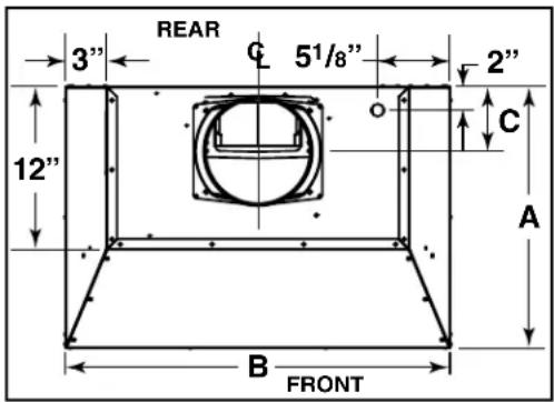
The custom hood must be constructed to fit the size and shape of the CPD hood liner.
See chart and illustration for details.
| HOOD LINER TOTAL | C WEIGHT | RANGE HOOD DIMENSIONS | |||
| SERIES M | MODEL *A *B | ||||
| CPD | CPDI362 | 73 LB | 2212" 34 | 38" 5 | 78" |
| CPDI482 | 88 LB | 2212" 46 | 58" 5 | 78" | |
| CPDI602 | 102 LB | 2212" 58 | 78" 5 | 78" | |
* Dimensions A and B include rivets head.
text_image
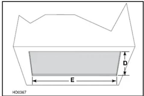
REAR 3" C 51/8" 2" 12" A B FRONTTo minimize the gap around the hood liner, take actual width and depth measurements of hood liner and add 1/16" to get D and E measurements. Cut the hole in the bottom of the cabinet according to dimensions. See chart and illustration for details.
| HOOD LINER | CUTOUT DIMENSIONS | ||
| SERIES | MODEL | D | E |
| CPD | CPDI362 | 22516" | 34716" |
| CPDI482 | 22516" | 46716" | |
| CPDI602 | 22516" | 581716" | |
text_image
HD0367 E D4. MOUNT CUSTOM HOOD INTERNAL FRAMEWORK
WARNING
The wood hood must be positively secured to wall studs or other wooden framework behind the drywall. Make sure it is capable of supporting its own weight and the weight of the CPD. Failure to do so may cause personal injury or damage to countertop or cooktop.
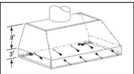
The CPD hood liner is supported by the custom hood internal framework with (12) #8 x ½" flat-head screws (16 screws for CPDI602) provided in parts bag.
Since the CPD hood liner mounting holes are located in front and rear sides (see illustration at right), plan to install wood frame at front and sides for support.
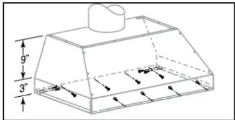
text_image
9" 3"5. REMOVE BAFFLE FILTERS
Remove tape on filters. Remove filters from power pack and set aside. It is recommended to start with the center filters.
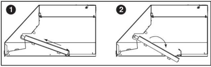
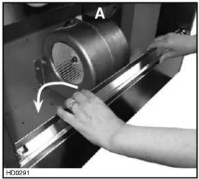
6. REMOVE GREASE DRIP RAIL
A. Lift grease drip rail to disengage it from the bottom panel.
(Blower shown is for reference only and does not represent actual blower in this product.)
natural_image
Close-up of hands operating a mechanical component with a curved arrow indicating motion (no visible text or symbols)7. REMOVE THE BOTTOM PANEL
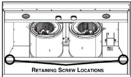
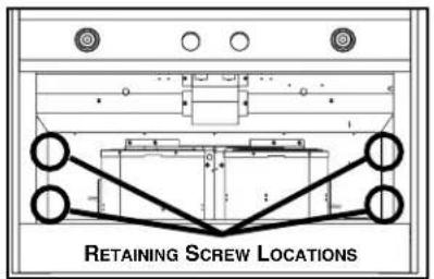
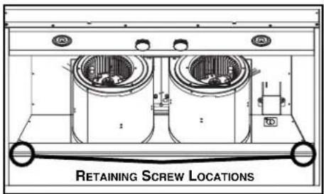
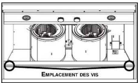
Using a Phillips screwdriver, remove both bottom filter filler panels.
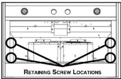
text_image
RETAINING SCREW LOCATIONSBOTTOM VIEW
Disassemble bottom panel, lift up and out, and set aside.
text_image
RETAINING SCREW LOCATIONSBOTTOM VIEW
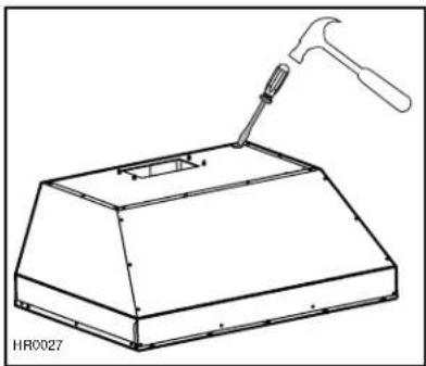
8. REMOVE THE KNOCK-OUT OPENING
From inside the hood liner, remove the wiring cover and set aside. Punch out the electrical knockout hole on top of the hood. Install the wire clamp (included in parts bag).
natural_image
Technical line drawing of a mechanical component with a hammer and hanger, no text or symbols present9. INSTALL THE 10" ADAPTER
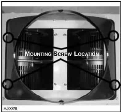
Using (4) no. M4 x 6 screws from parts bag, assemble the adapter on the top of the hood liner. Seal all joints with metal foil duct tape to eliminate air leaks.
text_image
MOUNTING SCREW LOCATION HJ002610. CONNECT THE WIRING
WARNING
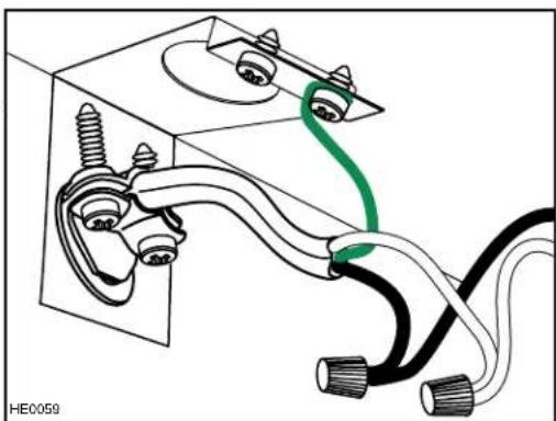
Risk of electric shock. Electrical wiring must be done by qualified personnel in accordance with all applicable codes and standards. Before connecting wires, switch power off at service panel and lock service disconnecting means to prevent power from being switched on accidentally.
Position the hood liner below the installed custom hood.
INTERNAL BLOWERS: Insert the house wiring cable through the wire clamp previously installed in step 8. Tighten the wire clamp to secure the cable. Connect cable into wiring box using wire connectors. Connect BLACK to BLACK, WHITE to WHITE and GREEN or bare wire under GREEN ground screw. DO NOT FORGET TO CONNECT THE GROUND. Reinstall wiring cover.
natural_image
Diagram of electrical wiring connections with black and white wires and a green cable (no text or symbols)11. INSTALL THE POWER PACK
CAUTION
Take care not to kink ducting when installing the power pack.
Using provided screws, install the hood liner inside the custom hood. Start with 2 screws on front corners, then use 4 screws for sides and use the remaining screws to finalize securing the front hood liner. (See figure at right for mounting screw specific locations.)
Make sure the adapter/damper (or the adapter) enters the ducting. When there is access to the top of the hood liner, seal connections with metal foil duct tape.
text_image
9" 3"12. REINSTALL BOTTOM PANEL
Lift the bottom panel and engage the hood liner metal tabs in bottom panel slots.
Secure the bottom panel to the hood liner using its screws.
text_image
RETAINING SCREW LOCATIONSBOTTOM VIEW
Re-install filter filler panels as shown.
text_image
RETAINING SCREW LOCATIONSBOTTOM VIEW
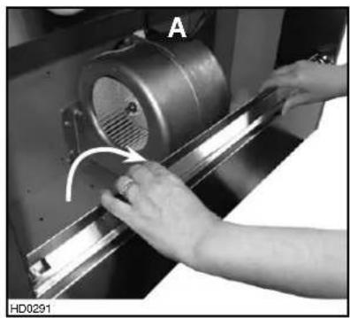
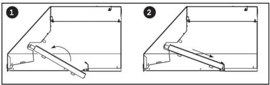
13. REINSTALL GREASE DRIP RAIL
A. Center the grease drip rail over the bottom panel edge and drop it in place.
(Blower shown is for reference only and does not represent actual blower in this product.)
natural_image
Close-up of hands operating a mechanical device with a circular component and a curved arrow indicating motion (no text or symbols visible)14. REINSTALL BAFFLE FILTERS
CAUTION
Remove protective plastic film covering baffle filters before installing them.
NOTE: It is recommended to install side filters first and finish with center filter(s).
-
Insert one end of baffle filter into the front channel of the hood.
-
Raise the other end toward the inside of hood liner and insert in the grease drip rail of the hood liner.
Replacement filters are available from your dealer. See label inside hood liner for size and part number.
natural_image
Technical line drawings of two mechanical components with arrows indicating motion (no text or symbols)15. LIGHT BULBS
This power pack must use shielded halogen lamps (120 V, 50 W PAR16 with GU10 base, 2 for CPDI362 and 4 for the CPDI482 & CPDI602), included.
NOTE: Before using lamps, remove shipping tape on them (if present).
WARNING
In order to prevent the risk of personal injury, do not install a lamp not suitable for use in enclosed fixtures.
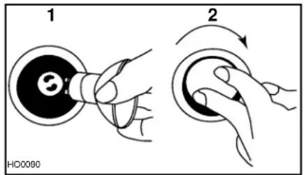
- Install the lamps by placing the bulb leads into their grooves in the socket.
- Gently push upwards and turn clockwise until secure.
WARNING
In order to prevent the risk of personal injury, do not install a lamp not suitable for use in enclosed fixtures.
text_image
1 2 HD0000To remove lamps, gently push upwards and turn counterclockwise to disengage bulb leads from their grooves.
NOTE: If need be, use a rubber dishwashing glove to add grip when removing the bulb; or use suction cup tool available from BEST® to ease removal of the bulbs. Contact BEST® Technical Support at 1-800-637-1453 to order suction cup tool, part number 99526707.
16. USE AND CARE
Baffle Filters
The baffle filters should be cleaned frequently. Use a warm detergent solution. Wash more often if your cooking style generates greater grease — like frying foods or wok cooking.
Remove baffle filters by pushing them towards the front of hood liner and rotating filters downward. Baffle filters are dishwasher safe. Allow filters to dry completely before reinstalling them.
Clean all-metal filters in the dishwasher using a non-phosphate detergent. Discoloration of the filter may occur if using phosphate detergent or as a result of local water conditions — but this will not affect filter performance. This discoloration is not covered by the warranty.
Grease Drip Rail
The grease drip rail should be cleaned frequently. Remove it from the hood liner (see step 6 on page 6) and use a warm detergent solution. As with the baffle filters, wash more often if your cooking style generates greater grease — like frying foods or wok cooking. Allow grease drip rail to dry completely before reinstalling it.
Interior Blowers Cleaning
Remove the filters in order to access the blowers. Vacuum blowers to clean. Do not immerse in water.
Hood Liner Cleaning
Stainless steel cleaning:
Do:
- Regularly wash with clean cloth or rag soaked with warm water and mild soap or liquid dish detergent.
• Always clean in the direction of original polish lines.
• Always rinse well with clear water (2 or 3 times) after cleaning. Wipe dry completely. - You may also use a specialized household stainless steel cleaner
Don't:
- Use any steel or stainless steel wool or any other scrapers to remove stubborn dirt.
• Use any harsh or abrasive cleansers. - Allow dirt to accumulate.
- Let plaster dust or any other construction residues reach the hood. During construction/renovation, cover the power pack to make sure no dust sticks to stainless steel surface.
Avoid when choosing a detergent:
- Any cleaners that contain bleach will attack stainless steel.
- Any products containing: chloride, fluoride, iodide, bromide will deteriorate surfaces rapidly.
- Any combustible products used for cleaning such as acetone, alcohol, ether, benzol, etc., are highly explosive and should never be used close to a range.
17. OPERATION
Always turn your hood liner on before you begin cooking to establish an air flow in the kitchen. Let the blower run for a few minutes to clear the air after you turn off the range. This will help keep the whole kitchen cleaner and brighter.
COOKTOP LIGHTING (HALOGEN)
The halogen lighting is controlled by the dial.
- POSITION 1: OFF
- POSITION 2: Low
- POSITION 3: HIGH
- POSITION 4: OFF
- Use 120 V, 50 W, MR16 with GU10 base or PAR16 with GU10 base, shielded halogen lamps (included).
BLOWER
The blower is controlled by the dial.
- POSITION 1: OFF
- POSITION 2: Low
• POSITION 3: MEDIUM - POSITION 4: HIGH
• HEAT SENTRY™
This hood liner is equipped with a Heat Sentry™ thermostat. This thermostat is a device that will start or speed up the blower if it senses excessive heat above the cooking surface.
1) If blower is OFF - it turns blower ON to HIGH speed.
2) If blower is ON at a lower speed setting – it turns the blower up to HIGH speed.
When the temperature level drops to normal, the blower will return to its original setting.
WARNING
The HEAT SENTRY can start the blower during a range top fire or other excessive heat situations even if the hood is turned off. In this case, it is impossible to turn the blower OFF with blower switch. If you must stop the blower, do it from the main electrical panel.
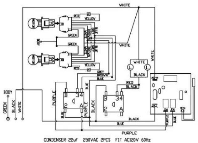
18. WIRING DIAGRAM
text_image
WHITE GREEN YELLOW GREEN RED GREEN WHITE GREEN RED GREEN YELLOW GREEN RED GREEN WHITE WHITE WHITE BLACK B 34 BLUE B 34 BLUE B 34 BLUE B 34 BLUE BODY GREEN BLACK WHITE PUBPLE PUBPLE PUBPLE CONDENSER 22uF 250VAC 2PCS FIT AC120V 60Hz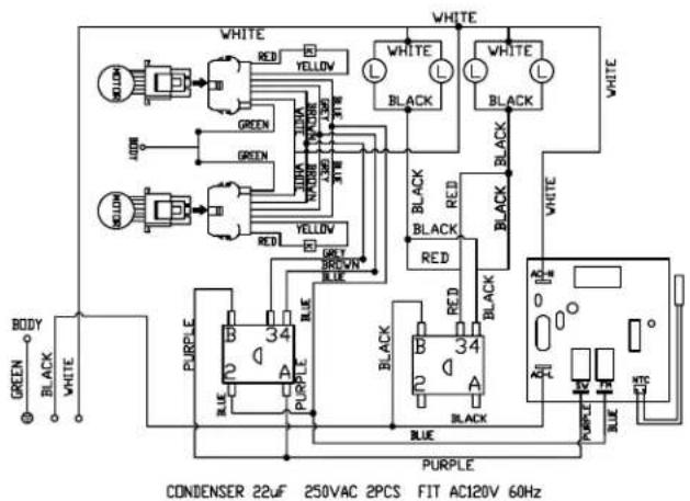
text_image
WHITE RED YELLOW GREEN GREEN RED YELLOW GREEN WHITE WHITE BLACK BLACK WHITE BLACK WHITE B 34 BLUE A PURPLE B 34 BLUE A PURPLE B 34 BLUE A PURPLE B 34 BLUE A PURPLE B 34 BLUE A PURPLE B 34 BLUE A PURPLE B 34 BLUE A PURPLE B 34 BLUE A PURPLE B 34 BLUE A PURPLE B 50VAC 2PCS FIT AC120V 60HzMODEL CPDI362SB MODELS CPDI482SB & CPDI602SB
19. WARRANTY
WARRANTY
ONE-YEAR LIMITED WARRANTY
Broan-NuTone LLC ("Broan-NuTone") warrants to the original consumer purchaser of its products that such products will be free from defects in materials or workmanship for a period of one year from the date of original purchase. THERE ARE NO OTHER WARRANTIES, EXPRESS OR IMPLIED, INCLUDING, BUT NOT LIMITED TO, IMPLIED WARRANTIES OF MERCHANTABILITY OR FITNESS FOR A PARTICULAR PURPOSE.
During this one-year period, Broan-NuTone will, at its option, repair or replace, without charge, any product or part which is found to be defective under normal use and service.
THIS WARRANTY DOES NOT EXTEND TO FLUORESCENT LAMP STARTERS, TUBES AND BULBS, FUSES, FILTERS, DUCTS, ROOF CAPS, WALL CAPS AND OTHER ACCESSORIES FOR DUCTING. This warranty does not cover (a) normal maintenance and service or (b) any products or parts which have been subject to misuse, negligence, accident, improper maintenance or repair (other than by Broan-NuTone), faulty installation or installation contrary to recommended installation instructions.
The duration of any implied warranty is limited to the one-year period as specified for the express warranty. Some states or provinces do not allow limitation on how long an implied warranty lasts, so the above limitation may not apply to you.
BROAN-NUTONE'S OBLIGATION TO REPAIR OR REPLACE, AT BROAN-NUTONE'S OPTION, SHALL BE THE PURCHASER'S SOLE AND EXCLUSIVE REMEDY UNDER THIS WARRANTY. BROAN-NUTONE SHALL NOT BE LIABLE FOR INCIDENTAL, CONSEQUENTIAL OR SPECIAL DAMAGES ARISING OUT OF OR IN CONNECTION WITH PRODUCT USE OR PERFORMANCE. Some states or provinces do not allow the exclusion or limitation of incidental or consequential damages, so the above limitation or exclusion may not apply to you.
This warranty gives you specific legal rights, and you may also have other rights, which vary from state to state or province to another. Any modification performed on this product without the authorization of Broan-NuTone will void this warranty. This warranty supersedes all prior warranties.
To qualify for warranty service, you must (a) notify Broan-NuTone at the address or telephone number stated below, (b) give the model number and part identification and (c) describe the nature of any defect in the product or part. At the time of requesting warranty service, you must present evidence of the original purchase date.
BEST®, 926 W. State Street, Hartford, WI 53027 (1-800-637-1453)
BEST®, 550 Lemire Blvd., Drummondville, QC, Canada (1-866-737-7770)
www.BestRangeHoods.com
Best CPD Series
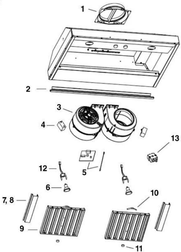
text_image
Exploded view diagram of a refrigerator with numbered parts for identification| KEYNO. | PART NO. DESCRIPTION | QTY. (POWER PACK WIDTH) | |||
| 36" 48" 60" | |||||
| 1 970 | 18874 A | DAPTER 10" ROUND 1 1 1 | |||
| 2 980 | 1093098010931 | GREASE RAIL 36"GREASE RAIL 48" & 60" | 1- | -1 | -1 |
| 3 970 | 18875 I | NTERNAL BLOWER (2 REQUIRED) | 2 | 2 | 2 |
| 4 992 | 71454 C | APACITOR 2 2 2 | |||
| 5 992 | 71455 C | ONTROL BOARD W/ HEAT SENTRY | 1 | 1 | 1 |
| 6 | V05921 | SHIELDED HALOGEN LAMPS (120 V, 50 W, GU-10) | 2 | 4 | 4 |
| 7 980 | 10933 F | ILTER FILLER (PAIR) (FOR 36") | 1 | - | - |
| 8 980 | 10936 F | ILTER FILLER (PAIR) (FOR 60") | - | - | 1 |
| 9 970 | 18876 B | AFFLE FILTER (INCLUDES ITEM 11) | 2 | 3 | 3 |
| 10 | 98010934 F | ILTER SPRING (SET OF 6) | 1 | 1 | 1 |
| 11 | 99840023 B | AFFLE FILTER KNOB WITH SCREWS (PAIR) | 2 | 3 | 3 |
| 12 | 97018879 L | AMP SHELL ASSEMBLY | 2 | 4 | 4 |
| 13 | 99271456 R | OTARY SWITCH | 2 2 2 | ||
| * | 97018878 P | ARTS BAG | 1 1 1 | ||
| * 995 | 26707 S | UCTION CUP BULB REMOVAL TOOL | 1 | 1 | 1 |
* NOT SHOWN.
best®
natural_image
Technical line drawing of a cabinet or enclosure with vertical slats and circular components (no text or symbols)SÉRIE CPD
BEST®; Hartford, Wisconsin www.BestRangeHoods.com 800-637-1453
BEST®; Drummondville, QC, Canada www.BestRangeHoods.com 866-737-7770
ENREGISTREZ VOTRE PRODUIT EN LIGNE À : www.BestRangeHoods.com/register
Pour de plus amples informations - visitez www.BestRangeHoods.com

AVERTISSEMENT AVERTISSEMENT
AFIN DE RÉDUIRE LES RISQUES D'INCENDIE, DE CHOC ÉLECTRIQUE OU DE BLESSURES CORPORELLES, VEUILLEZ OBSERVEZ LES DIRECTIVES SUIVANTES :
text_image
ARRIÈRE 3" C 51/8" 2" 12" A B AVANTnatural_image
Technical line drawing of a mechanical bracket assembly with no visible text or symbols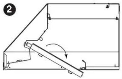
natural_image
Technical line drawing of a mechanical assembly with a lever and bracket (no text or symbols)natural_image
Close-up of hands operating a mechanical device with a curved arrow indicating motion (no visible text or symbols)7. ENLEVER LE PANNEAU INFÉRIEUR
text_image
EMPLACEMENT DES VISVUE DE DESSOUS
text_image
EMPLACEMENT DES VISVUE DE DESSOUS
8. ENLEVER L'OUVERTURE PRÉAMORCÉE
natural_image
Technical line drawing of a mechanical device with a hammer and hanger, no text or symbols present9. INSTALLER L'ADAPTATEUR DE 25 CM (10 PO)
natural_image
Pure electrical wiring diagram showing connections between components (no text or symbols)11. INSTALLATION DE LA PAROI DE LA HOTTE
ATTENTION
text_image
EMPLACEMENT DES VISVUE DE DESSOUS
text_image
EMPLACEMENT DES VISVUE DE DESSOUS
natural_image
Close-up of hands operating a mechanical device with a curved arrow indicating motion (no visible text or symbols)14. REPOSER LES FILTRES DE DÉFLECTEURS
ATTENTION
natural_image
Two technical diagrams showing mechanical assembly steps, labeled 1 and 2, with no visible text or symbols.15. AMPOULES
text_image
1 2 HO0090GARANTIE LIMITÉE D'UN AN
BEST®, 926 W. State Street, Hartford, WI 53027 (1-800-637-1453)
BEST®, 550 Lemire Blvd., Drummondville, QC, Canada (1-866-737-7770)
www.BestRangeHoods.com
Série Best CPD

text_image
Exploded view diagram of a refrigerator with numbered parts for identification| REPÈRE | N° DE PIÈCE DESCRIPTION | QTÉ (LARGEUR DE LA HOTTE) | |||
| 91 CM(36 PO) | 122 CM(48 PO) | 152 CM(60 PO) | |||
| 1 | 97018874 | ADAPTATEUR ROND DE 25 CM (10 PO) | 1 | 1 | 1 |
| 2 980 | 1093098010931 | GOUTTIÈRE À GRAISSES DE 91 CM (36 PO)GOUTTIÈRE À GRAISSES DE 122 CM (48 PO) ET 152 CM (60 PO) | 1- | -1 | -1 |
| 3 970 | 18875 V | ENTILATEUR INTERNE (2 REQUIS) | 2 | 2 | 2 |
| 4 992 | 71454 C | ONDENSATEUR | 2 2 2 | ||
| 5 992 | 71455 T | ABLEAU DE COMMANDE AVEC HEAT SENTRY | 1 | 1 | 1 |
| 6 | V05921 | AMPOULES HALOGÈNES À ÉCRAN (120 V, 50 W, GU-10) | 2 | 4 | 4 |
| 7 980 | 10933 P | ANNEAU DE FILTRE (PAIRE) (POUR 91 CM / 36 PO) | 1 | - | - |
| 8 980 | 10936 P | ANNEAU DE FILTRE (PAIRE) (POUR 152 CM / 60 PO) | - | - | 1 |
| 9 970 | 18876 F | ILTRE DE DÉFLECTEUR (COMPREND ARTICLE 11) | 2 | 3 | 3 |
| 10 | 98010934 R | ESSORT DE FILTRE (JEU DE 6) | 1 | 1 | 1 |
| 11 | 99840023 B | OUTON DE FILTRE DE DÉFLECTEUR (PAIRE) | 2 | 3 | 3 |
| 12 | 97018879 E | NSEMBLE DE DOUILLE D'AMPOULE | 2 | 4 | 4 |
| 13 | 99271456 | COMMUTATEUR ROTATIF | 2 2 2 | ||
| * 970 | 18878 C | OMMUTATEUR ROTATIF | 1 1 1 | ||
| * 995 | 26707 V | ENTOUSE POUR AMPOULE | 1 | 1 | 1 |
* NON ILLUSTRÉ.
best®
natural_image
Technical line drawing of a cabinet or enclosure with vertical slats and circular components (no text or symbols)SERIE CPD
BEST®; Hartford, Wisconsin www.BestRangeHoods.com 800-637-1453
BEST®; Drummondville, QC, Canada www.BestRangeHoods.com 866-737-7770
REGISTRE SU PRODUCTO EN LÍNEA EN: www.BestRangeHoods.com/register
Si desea información adicional, visite www.BestRangeHoods.com

ADVERTENCIA
PARA REDUCIR EL RIESGO DE INCENDIOS, DESCARGAS ELECTRICAS O LESIONES PERSONALES, SIGA LAS SIGUIENTES PRECAUCIONES:
natural_image
Technical line drawing of a mechanical bracket assembly (no text or symbols)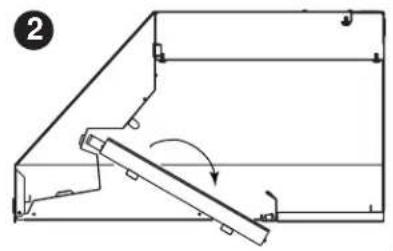
natural_image
Technical line drawing of a mechanical assembly with a lever and bracket (no text or symbols)6. RETIRE EL RIEL PARA ESCURRIMIENTOS DE GRASA
natural_image
Close-up of hands operating a mechanical component with a curved arrow indicating motion (no visible text or symbols)7. RETIRE EL PANEL INFERIOR
natural_image
Technical line drawing of a mechanical device with a hammer and handle (no text or symbols)9. INSTALE EL ADAPTADOR DE 10 PULG. (25 CM)
natural_image
Pure electrical circuit lines without any symbolsnatural_image
Close-up of hands operating a mechanical device with a curved arrow indicating motion (no visible text or symbols)14. REINSTALE LOS FILTROS DEFLECTORES
PRECAUCIÓN
natural_image
Technical line drawings of two mechanical components with directional arrows indicating motion (no text or symbols)15. BOMBILLAS
BEST®, 926 W. State Street, Hartford, WI 53027 (1-800-637-1453)
BEST®, 550 Lemire Blvd., Drummondville, QC, Canada (1-866-737-7770)
www.BestRangeHoods.com
Best Serie CPD

text_image
Exploded view diagram of a refrigerator with numbered parts for identification| CLAVEN.° | N.°DE PIEZA | DESCRIPCIÓN | CANT. (ANCHO DEL PAQUETE DE POTENCIA) | ||
| 36 pulg.(91 cm) | 48 pulg.(122 cm) | 60 pulg.(152 cm) | |||
| 1 | 97018874 | ADAPTADOR REDONDO DE 10 PULG. (25 CM) | 1 | 1 | 1 |
| 2 9801093098010931 | RIEL PARA GRASA DE 36 PULG. (91 CM)RIEL PARA GRASA DE 48 PULG. (122 CM) Y 60 PULG. (152 CM) | 1- | -1 | -1 | |
| 3 97018875 V | ENTILADOR INTERNO (SE REQUIEREN 2) | 2 | 2 | 2 | |
| 4 99271454 C | APACITOR | 2 2 2 | |||
| 5 99271455 T | ARJETA DE CONTROL CON HEAT SENTRY | 1 | 1 | 1 | |
| 6 V05921 | LÁMPARAS DE HALÓGENO PROTEGIDAS (120 V, 50 W, GU-10) | 2 | 4 | 4 | |
| 7 98010933 R | ELLENO DE FILTRO (PAR) (PARA 36") | 1 | - | - | |
| 8 98010936 R | ELLENO DE FILTRO (PAR) (PARA 60") | - | - | 1 | |
| 9 97018876 F | ILTRO DEFLECTOR (INCLUYE EL ELEMENTO 11) | 2 | 3 | 3 | |
| 10 98010934 R | ESORTE PARA FILTRO (JUEGO DE 6) | 1 | 1 | 1 | |
| 11 99840023 P | ERILLA PARA FILTRO DEFLECTOR CON TORNILLOS (PAR) | 2 | 3 | 3 | |
| 12 97018879 C | ONJUNTO DE CUBIERTA DE LÁMPARA | 2 | 4 | 4 | |
| 13 99271456 I | NTERRUPTOR GIRATORIO | 2 2 2 | |||
| * 97018878 B | OLSA CON PIEZAS | 1 | 1 | 1 | |
| * 99526707 H | ERRAMIENTA PARA QUITAR BOMBILLAS CON TAZA DE SUCCIÓN | 1 | 1 | 1 | |
* NO SE MUESTRA.