WTT32I336SB - Basket BEST - Free user manual and instructions
Find the device manual for free WTT32I336SB BEST in PDF.
Download the instructions for your Basket in PDF format for free! Find your manual WTT32I336SB - BEST and take your electronic device back in hand. On this page are published all the documents necessary for the use of your device. WTT32I336SB by BEST.
USER MANUAL WTT32I336SB BEST
Hartford, Wisconsin REGISTER YOUR PRODUCT ONLINE AT : www.BestRangeHoods.com/register For additional Information visit www.BestRangeHoods.com HB0103- 2 -
READ AND SAVE THESE INSTRUCTIONS
WARNING TO REDUCE THE RISK OF FIRE, ELECTRIC SHOCK, OR INJURY TO PERSON(S) OBSERVE THE FOLLOWING:
1. Use this unit only in the manner intended by the manufacturer. If you have
questions, contact the manufacturer at the address or telephone number listed in the warranty.
2. Before servicing or cleaning unit, switch power off at service panel and lock
service disconnecting means to prevent power from being switch on accidentally. When the service disconnecting means cannot be locked, securely fasten a prominent warning device, such as a tag, to the service panel.
3. Installation work and electrical wiring must be done by qualified personnel
in accordance with all applicable codes and standards, including fire-rated construction codes and standards.
4. Sufficient air is needed for proper combustion and exhausting of gases
through the flue (chimney) of fuel burning equipment to prevent backdrafting. Follow the heating equipment manufacturer’s guidelines and safety standards such as those published by the National Fire Protection Association (NFPA), the American Society for Heating, Refrigeration and Air Conditioning Engineers (ASHRAE) and the local code authorities.
5. This product may have sharp edges. Be careful to avoid cuts and abrasions
during installation and cleaning.
6. When cutting or drilling into wall or ceiling, do not damage electrical wiring and
other hidden utilities.
7. Ducted fans must always be vented to the outdoors.
8. To reduce the risk of fire, use only steel ductwork.
9. Do not use this unit with any other solid-state speed control device.
10. Do not operate any fan with a damaged cord or plug. Discard fan or return to
an authorized service facility for examination and/or repair.
11. GROUNDING INSTRUCTION: The appliance must be grounded. In the event
of an electrical short circuit, grounding reduces the risk of electric shock by providing an escape wire for the electric current. The appliance is equipped with a cord having a grounding wire with a grounding plug. The plug must be plugged into an outlet that is properly installed and grounded. WARNING: Improper grounding can result in a risk of electric shock. Consult a qualified electrician if the grounding instructions are not completely understood, or if doubt exists as to whether the appliance is properly grounded. Do not use an extension cord. If the power supply cord is too short, have a qualified electrician install an outlet near the appliance.
1. For indoor use only.
2. For general ventilating use only. Do not use to exhaust hazardous or explosive
materials and vapors.
3. To avoid motor bearing damage and noisy and/or unbalanced impeller, keep
drywall spray, construction dust, etc. off power unit.
4. Your hood motor has a thermal overload which will automatically shut off the
motor if it becomes overheated. The motor will restart when it will cool down. If the motor continues to shut off and restart, have the hood serviced.
5. The bottom of the hood MUST NOT BE LESS than 24” and at a maximum of
30” above cooktop for best capture of cooking impurities.
6. Two installers are recommended because of the size of this hood.
7. To reduce risk of fire and to properly exhaust air, be sure to duct air outside. Do
not exhaust air into spaces within walls or ceilings or into attics, crawl spaces, or garages.
8. Be careful when installing the decorative flue and hood, they may have sharp
9. Please read specification label on product for further information and
requirements. TO REDUCE THE RISK OF A RANGE TOP GREASE FIRE: a) Never leave surface units unattended at high settings. Boilovers cause smoking and greasy spillovers that may ignite. Heat oils slowly on low or medium settings. b) Always turn hood ON when cooking at high heat or when cooking flaming foods (i.e. Crêpes Suzette, Cherries Jubilee, Peppercorn Beef Flambé). c) Clean ventilating fans frequently. Grease should not be allowed to accumulate on fan or filters. d) Use proper pan size. Always use cookware appropriate for the size of the surface element. TO REDUCE THE RISK OF INJURY TO PERSON(S) IN THE EVENT OF A RANGE TOP GREASE FIRE, OBSERVE THE FOLLOWING*:
1. SMOTHER FLAMES with a close-fitting lid, cookie sheet, or metal tray, then turn
off the burner. BE CAREFUL TO PREVENT BURNS. IF THE FLAMES DO NOT GO OUT IMMEDIATELY, EVACUATE AND CALL THE FIRE DEPARTMENT.
2. NEVER PICK UP A FLAMING PAN – You may be burned.
3. DO NOT USE WATER, including wet dishcloths or towels – This could cause
a violent steam explosion.
4. Use an extinguisher ONLY if:
A. You know you have a Class ABC extinguisher and you know how to operate it. B. The fire is small and contained in the area where it started. C. The fire department has been called. D. You can fight the fire with your back to an exit.
- Based on “Kitchen Fire Safety Tips” published by NFPA.- 4 - OPERATION Always turn your hood on before you begin cooking to establish an air flow in the kitchen. Let the blower run for a few minutes to clear the air after you turn off the range. The hood is operated using the push buttons on the front panel.
When a blower speed is selected, press this switch to activate the delay func- tion. The delay button will illuminate to indicate this function is activated. The blower will continue to operate for 5 minutes and will stop automatically. To cancel the delay function, press the delay switch once again.
B. START / STOP / SPEED SELECTION SWITCHES
Press the switch corresponding to the desired blower speed (from 1 for low speed to 4 for high speed). The chosen switch will light. To turn off the blower, press once more on the corresponding blower speed switch; the switch light will shut off. C. MASTER OFF / FILTER MAINTENANCE / HEAT SENTRY™ (TRIPLE FUNCTION SWITCH) To turn off the blower and the light simultaneously, press this switch once. After 25 hours of operation, this switch will light to indicate the filters and the blower wheel(s) need to be cleaned in order to maintain efficient operation of the unit. The switch light will stay on until the function is reset by pressing this switch for 3 seconds. The light indicator is used for the Heat Sentry function as well. HEAT SENTRY: When an excessively high temperature is detected, the Heat Sentry takes control over the blower and sets it on speed 3. The triple-function switch will flash.The blower will remain on until the heat condition is back to normal. It will then return to the speed previously selected.
WARNING: The Heat Sentry can start the blower even if the hood is
turned off. When this situation occurs, it is impossible to turn the blower off using the push buttons. If you must stop the blower, do it from the main electrical panel.
This switch allows three different lighting levels according to your needs. Press once for nightlight, twice for normal or three times to obtain full intensity. To shut off the lights without turning off the blower, press once more. HC0023 A B C D- 5 -
(switched low voltage)
20 GAUGE BELL WIRE FOR LOW
The hood is compatible with Broan Make-Up Air Damper Model MD6T or Model MD8T (optional). Purchase separately. Make the connection to the Make-Up Air Damper with low voltage wiring, as shown. See Make-Up Air Damper instructions for additional information.- 6 - CLEANING & MAINTENANCE For performance, appearance, and health reasons, clean filter, fan and grease-laden surfaces regularly. Use only a clean cloth and mild detergent solution on stainless and painted surfaces. Clean all-metal filters in the dishwasher using a non-phosphate detergent. Discoloration of the filter may occur if using phosphate detergents, or as a result of local water conditions - but this will not affect filter performance. This discoloration is not covered by the warranty. Clean the non-duct recirculating filter surfaces frequently with a damp cloth and a mild detergent. DO NOT immerse filters in water or put in dishwasher. Change the non- duct recirculating filters every 6 months. For replacement non-duct recirculating filters - purchase S97018968 or Model AFCWTT32 (for 30” wide hood) or S97019039 or Model AFCWTT326 (for 36” and 42” wide hoods). The motor is permanently lubricated and never needs oiling. If the motor bearings make excessive or unusual noise, replace the blower assembly with an exact service replacement. LIGHT BULBS
Bulbs may be hot. Always allow bulbs to cool down before removing them. Use (2) Halogen Bulbs (included with hood) - 120 V, 50 W, shielded halogen bulbs - MR16 with GU10 base. (3 bulbs for 42” & 48” hoods.) NOTE: Suction Cup Tool (included with hood) can be used to install and remove light bulbs. Align pins on bulb with large diameter opening on socket, then push bulb in towards hood and rotate clockwise until firmly seated. The position of the bulb socket (depth) is adjustable and may require adjustment when: a) certain brands of bulbs are difficult to install. b) the bulb protrudes too far below the light panel. LAMP SOCKET BRACKET SCREWS LIGHT PANEL To change the depth of bulb sockets: - Remove screws on light panel – set screws aside - Remove Light Panel. - Loosen 2 Screws holding Lamp Socket Bracket to Light Panel. - Adjust socket/bracket to desired depth. - Re-tighten screws securely. - Re-attach light panel with screws that were previously set aside. (1) PUSH IN (2) ROTATE CLOCKWISE SUCTION CUP TOOL HALOGEN BULB- 7 -
1. Decide where the ductwork will run between the hood and the outside.
2. A straight, short duct run will allow the hood to perform most efficiently.
3. Long duct runs, elbows and transitions will reduce the performance of the
hood. Use as few of them as possible. Larger ducting may be required for best performance with longer duct runs.
4. Install wall cap or roof cap. Connect round metal ductwork to cap and work back
towards the hood location. Use duct tape to seal the joints between ductwork sections.
MEASURE THE INSTALLATION
The minimum hood distance above cooktop MUST NOT BE LESS than 24”. A maximum of 30” above cooktop is highly recommended for best capture of cooking impurities. Distances over 30” are at the installer and users discretion; providing that the ceiling height permits. HOOD
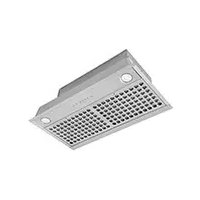
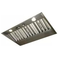
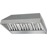
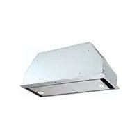
Unpack hood and check contents. You should receive:
1 - Decorative Flue Assembly (consisting of upper and lower flue)
1 - Upper Flue Mounting Bracket
2 - Aluminum Grease Filters (installed on hood) (3 - on 48” model)
1 - 10” Damper / Duct Connector (for 48” model)
1 - Damper Diverter (for 48” model)
1 - Parts Bag containing:
6 - Mounting Screws (4mm x 38mm Cross Recessed Pan Head)
2 - Mounting Screws (4mm x 12mm Cross Recessed Pan Head)
4 - Mounting Screws (4mm x 8mm Cross Recessed Pan Head) (6 for 48” model)
1 - Suction Cup Tool (for bulb installation / removal)
6 MOUNTING SCREWS (4mm x 38mm Cross Recessed Pan Head) 2 MOUNTING SCREWS (4mm x 12mm Cross Recessed Pan Head) DECORATIVE FLUE ASSEMBLY UPPER FLUE MOUNTING BRACKET BULB SUCTION CUP TOOL HOOD ASSEMBLY
(48” model only) 4 MOUNTING SCREWS (4mm x 8mm Cross Recessed Pan Head) (6 for 48” model)- 9 - 24” MAX. HOOD CENTERLINE
GROUNDING INSTRUCTIONS This appliance must be grounded. In the event of an electrical short circuit, grounding reduces the risk of electric shock by providing an escape wire for the electric current. This appliance is equipped with a cord having a grounding wire with a grounding plug. The plug must be plugged into an outlet that is properly installed and grounded. Position the electrical outlet within the space covered by the decorative flue and where it will not interfere with the round duct. Make sure the outlet is no further than 24” from the top of the hood chassis, and that the outlet does not interfere with a mounting bracket fastening area or where the decorative flue touches the wall. NOTE: A clock outlet can be used to minimize clearance related issues with the range hood plug.- 10 -
INSTALL THE HOOD MOUNTING SUPPORT
1. Construct structural wall framing that is flush with interior surface of wall studs. Make sure the framing is centered over installation location. NOTE Hood distance above cooktop is: Minimum 24”, Maximum 30”. 9-ft. and 10-ft. ceilings may require Flue Extension, Model AEWTT32SB (for 30”, 36” & 42” wide hoods) or Model AEWTT328SB (for 48” wide hoods), depending on installation height (purchase separately). See charts below for additional installation height information.2. After wall surface is finished, fasten (2) 4mm x 38mm screws at the locations shown below. DO NOT TIGHTEN screws all the way - leave approximately 1/4” between screw head and wall.
/8 ”STRUCTURALFRAMINGSTRUCTURALFRAMING HOOD 24" 25"26" 27" 28"29" 30" CeilingHeight 8 Feet 37-1/8" 38-1/8" 39-1/8" 40-1/8"41-1/8"*42-1/8"*43-1/8" 9 Feet9 Feet with AEWTT32SB10 Feet with AEWTT32SB* Not applicable for non-duct installation. ** For non-duct installation, use upper flue from AEWTT32SB and lower flue from standard hood.Desired Hood Distance (Above 36" High Cooktop) 43-1/8"Upper Mounting Screws Location (Distance above 36" High Cooktop) (Dimension “A”) **37-1/8" **38-1/8" **39-1/8" 37-1/8" 38-1/8" 39-1/8" 40-1/8"41-1/8"42-1/8" 43-1/8" For 30-in., 36-in., & 42-in. wide hoods- 11 -
/8 ”6 /8 ”STRUCTURALFRAMINGSTRUCTURALFRAMING HOOD 24" 25"26" 27" 28"29" 30" CeilingHeight 8 Feet 36-1/8" 37-1/8" 38-1/8" 39-1/8"40-1/8"41-1/8" 42-1/8" 9 Feet9 Feet with AEWTT328SB10 Feet with AEWTT328SB Desired Hood Distance (Above 36" High Cooktop) 42-1/8"Upper Mounting Screws Location (Distance above 36" High Cooktop) (Dimension “A”) 36-1/8" 37-1/8" 38-1/8" 36-1/8" 37-1/8" 38-1/8" 39-1/8"40-1/8"41-1/8" 42-1/8" 41-1/8"40-1/8" For 48-in. wide hoods- 12 - Flush with the ceiling Center of installation Upper flue mounting bracket slots Ceiling
1. Center the flue mounting bracket over the hood location and flush with the
ceiling. Secure the upper flue bracket to the wall using (2) 4mm x 38mm mounting screws. Note: Drywall anchors may be required (not included).
2. Tighten the screws completely. Make sure that the bracket is tight against the
3. Remove the protective plastic film covering the decorative flue and the hood at
4. Remove the grease filters by pulling down the metal latch tab and tilting filters
5. Remove all internal foam fillers that support the blower assembly inside the
6. For 48” wide hood only: Attach damper / diverter to top of hood using (2) 4mm
x 8mm mounting screws.
7. Attach the damper / duct connector (8” diameter for 30”, 36”, and 42” wide hoods
and 10” diameter for 48” wide hood) using (4) 4mm x 8mm mounting screws.
(10” for 48” wide hood)
8. Align the two outer keyhole slots on the hood with the mounting screws that
were partially tightened into the wall framing. Ensure that hood is seated entirely on mounting screws and that hood is level. Then tighten screws completely.
9. Install (2) 4mm x 38mm long screws into the holes inside the hood and tighten
10. Reinstall grease filters by aligning rear filter tabs with slots in the hood. Pull
down the metal latch tab, push filters into position and release. Make sure filters are securely engaged after installation.
11. Measure and install steel ductwork to hood duct connector and ductwork
rough-in on ceiling or wall. Use duct tape to make all joints secure and air tight.
12. Plug power cord into wall outlet.- 14 -
13. Slide the upper decorative flue section into the lower decorative flue section.
NOTE For ducted applications, the louvers on the upper flue should be hidden by positioning the louvers down, inside of the lower flue.
14. Carefully place the upper/lower flue assembly into the recessed area of the
15. Slide the upper flue upward until it is aligned with its mounting bracket. The
bracket should be inside the flue. Secure the upper flue to the upper flue mounting bracket using (2) 4mm x 12mm mounting screws. NOTE 9-10 ft. ceilings may require Flue Extension Model AEWTT32SB (for 30”, 36” & 42” wide hoods) or Model AEWTT328SB (for 48” wide hoods), depending on installation height (purchase separately). Discard the upper and lower flues supplied with your hood and replace them with Flue Extensions.- 15 -
(Non-Ducted Hoods Only) NON-DUCT KIT MODEL ANKWTT320 OR ANKWTT326 CONTENTS NOTE Non-ducted installations require Non-Duct Kit, Model ANKWTT320 (for 30” wide hood) or Model ANKWTT326 (for 36” or 42” wide hood).
1. Center the non-duct
plenum over the hood location and flush with the ceiling. Secure the non-duct plenum to the wall using (2) 4mm x 38mm mounting screws. Note: Drywall anchors may be needed (not included).
2. Tighten the screws
completely. Make sure that the non-duct plenum is tight against the wall and ceiling.
3. Remove damper flaps
from damper / duct connector and discard flaps.
4. Remove the protective
plastic film covering the decorative flue and the hood at this time.
5. Attach the 8” round duct connector to the top of the hood using (4) 4mm x
8mm mounting screws.
6. Remove the grease filters by pulling down the metal latch tab and tilting filters
7. Remove all internal foam fillers that support the blower assembly inside the
Flush with the ceilingCenter of installationUpper flue mounting bracket slotsCeiling- 16 -
outer keyhole slots on the hood with the mounting screws that were partially tightened into the wall framing. Ensure that hood is seated entirely on mounting screws and that hood is level. Then tighten screws completely.
x 38mm long screws into the holes inside the hood and tighten them securely.
ducted filters to grease filter using (8) filter clips.
11. Reinstall grease/
non-duct filter assembly by aligning rear filter tab with slots in the hood. Pull down the metal latch tab, push filters into position and release. Make sure filters are securely engaged after installation.- 17 -
12. Measure and install section of flexible metal ductwork (included with
ANKWTT320 or ANKWTT326) to damper/duct connector and bottom of non- duct plenum. Use duct tape to make all joints secure and air tight. CAUTION Do not use plastic duct.
13. Plug power cord into wall outlet.
14. Slide the upper decorative flue section into the lower decorative flue section.
NOTE For non-ducted applications, the upper flue should be oriented so the louvers are towards the ceiling.
15. Carefully place the
upper/lower flue assembly into the recessed area of the hood.
flue upward until it is aligned with the non-duct plenum. The non-duct plenum should be inside the flue. Secure the upper flue to the non-duct plenum using (2) 4mm x 12mm mounting screws. NOTE 9-10 ft. ceilings may require Flue Extension Model AEWTT32SB depending on installation height (purchase separately). Discard the upper and lower flues supplied with your hood and replace them with Flue Extension Model AEWTT32SB. DUCT LENGTH DECORATIVE FLUE 8” ROUND FLEXIBLE METAL DUCT NON-DUCT PLENUM DAMPER / DUCT CONNECTOR- 18 - SERVICE PARTS KEY PART NO. DESCRIPTION QTY. 1 S99528405 Decorative Upper and Lower Flues 1 2 S99528407 Motor / Blower Assembly 1 3 S99528408 Light Socket (30” & 36” wide hoods) 2 (includes mounting hardware) Light Socket (42” wide hood) 3 (includes mounting hardware) 4 S99528409 Light Socket Bracket (30” & 36” wide hoods) 2 (includes mounting hardware) Light Socket Bracket (42” wide hood) 3 (includes mounting hardware) 5 S99528410 User Interface Assembly 1 6 S99528411 User Interface Cable 1 7 S99528412 Control Board 1 8 S99528414 Aluminum Grease Filter (30” wide hood) 2 S99528415 Aluminum Grease Filter (36” & 42” wide hoods) 2 9 S97018968 Non-Duct Recirculation Filter (30” wide hood) 2 S97019039 Non-Duct Recirculation Filter (36” & 42” wide hoods) 2 10 S99528418 8” Damper Assembly 1 11 S99528429 8” Dia. Expandable Flexible Aluminum Duct 1 12 S99528421 Non-Duct Plenum Assembly 1 13 S99528422 Upper Flue Mounting Bracket 1 14 V05921 50W MR16 GU10 Halogen Lamp (30” & 36” wide hoods) 2 50W MR16 GU10 Halogen Lamp (42” wide hood) 3
- Not shown. Order service parts by Part No. - not by Key No. 30”, 36” & 42” Wide Models- 19 - Replacement parts can be ordered on our website: www.BestRangeHoods.com SERVICE PARTS
- Not shown. Order service parts by Part No. - not by Key No.- 21 - Replacement parts can be ordered on our website: www.BestRangeHoods.com SERVICE PARTS
48” Wide Model- 22 - WARRANTY ONE YEAR LIMITED WARRANTY FOR BEST PRODUCTS Broan-NuTone LLC (Broan-NuTone) warrants to the original consumer purchaser of Best products that such products will be free from defects in materials or work- manship for a period of one year from the date of original purchase. THERE ARE NO OTHER WARRANTIES, EXPRESS OR IMPLIED, INCLUDING, BUT NOT LIMITED TO, IMPLIED WARRANTIES OR MERCHANT ABILITY OR FITNESS FOR A PARTICULAR PURPOSE. During this one-year period, Broan-NuTone will, at its option, repair or replace, without charge, any product or part which is found to be defective under normal use and service. THIS WARRANTY DOES NOT EXTEND TO FLUORESCENT LAMP STARTERS, TUBES, HALOGEN AND INCANDESCENT BULBS, FUSE, FILTERS, DUCTS, ROOF CAPS, WALL CAPS AND OTHER ACCESSORIES FOR DUCTING. This warranty does not cover (a) normal maintenance and service or (b) any products or parts which have been subject to misuse, negligence, accident, improper maintenance or repair (other than by Broan-NuTone), faulty installation or instal- lation contrary to recommended installation instructions. The duration of any implied warranty is limited to the one-year period as speci- fied for the express warranty. Some states do not allow limitation on how long an implied warranty lasts, so the above limitation may not apply to you. BROAN-NUTONE’S OBLIGATION TO REPAIR OR REPLACE, AT BROAN- NUTONE’S OPTION, SHALL BE THE PURCHASER’S SOLE AND EXCLUSIVE REMEDY UNDER THIS WARRANTY. BROAN-NUTONE SHALL NOT BE LIABLE FOR INCIDENTAL, CONSEQUENTIAL OR SPECIAL DAMAGES ARISING OUT OF OR IN CONNECTION WITH PRODUCT USE OR PERFORMANCE. Some states do not allow the exclusion or limitation of incidental or consequential dam- ages, so the above limitation or exclusion may not apply to you. This warranty gives you specific legal rights, and you may also have other rights, which vary from state to state. This warranty supersedes all prior warranties. To qualify for warranty service, you must (a) notify Broan-NuTone at the address stated below or telephone number stated below, (b) give the model number and part identification and (c) describe the nature of any defect in the product or part. At the time of requesting warranty service, you must present evidence of the original purchase date. In USA - BEST®, 926 W. State Street, Hartford, WI 53027 (800-558-1711) In Canada - BEST®, 550 Lemire Blvd., Drummondville, QC J2C 7W9 (866-737-7770) www.BestRangeHoods.com 99045047BSérie WTT32I Aux États-Unis - BEST