K313930SS - Basket BEST - Free user manual and instructions
Find the device manual for free K313930SS BEST in PDF.
Download the instructions for your Basket in PDF format for free! Find your manual K313930SS - BEST and take your electronic device back in hand. On this page are published all the documents necessary for the use of your device. K313930SS by BEST.
USER MANUAL K313930SS BEST
READ AND SAVE THESE INSTRUCTIONS
1. Use this unit only in the manner intended by
the manufacturer. If you have questions, con- tact the manufacturer at the address or tele- phone number listed in the warranty.
2. Before servicing or cleaning unit, switch power
off at service panel and lock service panel to prevent power from being switched on accidentally. When the service disconnecting means cannot be locked, securely fasten a prominent warning device, such as a tag, to the service panel.
3. Installation work and electrical wiring must be
done by a qualified person(s) in accordance with all applicable codes and standards, includ- ing fire-rated construction codes and stan- dards.
4. Sufficient air is needed for proper combustion
and exhausting of gases through the flue (chim- ney) of fuel burning equipment to prevent backdrafting. Follow the heating equipment manufacturer’s guidelines and safety stan- dards such as those published by the National Fire Protection Association (NFPA), and the American Society for Heating, Refrigeration and Air Conditioning Engineers (ASHRAE), and the local code authorities.
5. When cutting or drilling into wall or ceiling, do
not damage electrical wiring and other hidden utilities.
6. Ducted fans must always be vented to the out-
7. Do not use this unit with any solid-state speed
8. To reduce the risk of fire, use only steel
9. This unit must be grounded.
TO REDUCE THE RISK OF A RANGE TOP GREASE FIRE: A. Never leave surface units unattended at high settings. Boilovers cause smoking and greasy spillovers that may ignite. Heat oils slowly on low or medium settings. B. Always turn hood ON when cooking at high heat or when cooking flaming foods. C. Clean ventilating fans frequently. Grease should not be allowed to accumulate on fan or filter. D. Use proper pan size. Always use cookware appropriate for the size of the surface element. WARNING TO REDUCE THE RISK OF INJURY TO PER- SONS IN THE EVENT OF A RANGE TOP
GREASE FIRE, OBSERVE THE FOLLOWING:*
1. SMOTHER FLAMES with a close-fitting lid,
cookie sheet, or metal tray, then turn off the burner. BE CAREFUL TO PREVENT BURNS. If the flames do not go out immediately, EVACU- ATE AND CALL THE FIRE DEPARTMENT.
3. DO NOT USE WATER, including wet dishcloths
or towels - violent steam explosion will result.
4. Use an extinguisher ONLY if:
A. You know you have a Class ABC extin- guisher and you already know how to op- erate it. B. The fire is small and contained in the area where it started. C. The fire department is being called. D. You can fight the fire with your back to an exit.
- Based on “Kitchen Fire Safety Tips” pub- lished by NFPA. CAUTION
1. To reduce risk of fire and to properly exhaust air,
be sure to duct air outside. Do not vent exhaust air into spaces within walls or ceilings or into attics, crawl spaces, or garages.
2. Take care when using cleaning agents or
3. Avoid using food products that produce flames
under the Range Hood.
4. For general ventilating use only. Do not use to
exhaust hazardous or explosive materials and vapors.
5. To avoid motor bearing damage and noisy and/
or unbalanced impellers, keep drywall spray, construction dust, etc. off power unit.
6. Your hood motor has a thermal overload which
will automatically shut off the motor if it becomes overheated. The motor will restart when it cools down. If the motor continues to shut off and restart, have the hood serviced.
7. For best capture of cooking impurities, the
bottom of the hood should be a minimum of 24" and a maximum of 30" above the cooking sur- face.
8. Two installers are recommended because of the
large size and weight of this hood.
9. Please read specification label on product for
further information and requirements.- 4 -
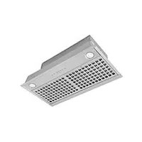
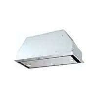
Unpack hood and check contents. You should receive:
1 - Decorative Flue Assembly
1 - Parts Bag containing:
1 - Mounting Bracket
1 - Discharge Collar
1 - Flue Mounting Bracket
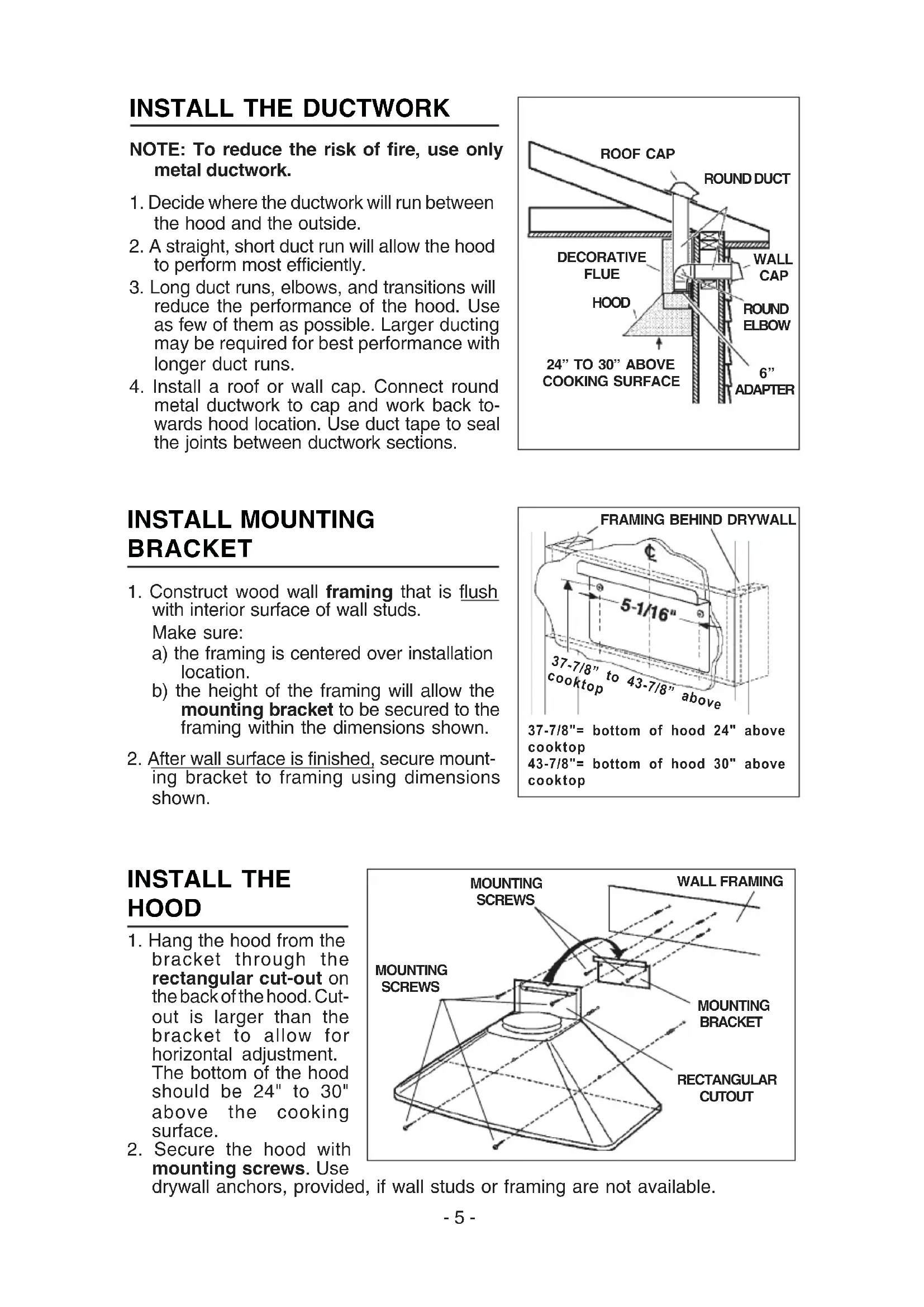
1. Construct wood wall framing that is flush
with interior surface of wall studs. Make sure: a) the framing is centered over installation location. b) the height of the framing will allow the mounting bracket to be secured to the framing within the dimensions shown.
2. After wall surface is finished, secure mount-
ing bracket to framing using dimensions shown.
NOTE: To reduce the risk of fire, use only metal ductwork.
1. Decide where the ductwork will run between
the hood and the outside.
2. A straight, short duct run will allow the hood
to perform most efficiently.
3. Long duct runs, elbows, and transitions will
reduce the performance of the hood. Use as few of them as possible. Larger ducting may be required for best performance with longer duct runs.
4. Install a roof or wall cap. Connect round
metal ductwork to cap and work back to- wards hood location. Use duct tape to seal the joints between ductwork sections. MOUNTING SCREWS RECTANGULAR CUTOUT WALL FRAMING MOUNTING BRACKET INSTALL THE HOOD
1. Hang the hood from the
bracket through the rectangular cut-out on the back of the hood. Cut- out is larger than the bracket to allow for horizontal adjustment. The bottom of the hood should be 24" to 30" above the cooking surface.
2. Secure the hood with
mounting screws. Use drywall anchors, provided, if wall studs or framing are not available. MOUNTING SCREWS- 6 - WIRING Note: This range hood must be properly grounded. The unit should be installed by a qualified electrician in accordance with all applicable national and local electrical codes. GROUNDING INSTRUCTIONS This appliance must be grounded. In the event of an electrical short circuit, grounding reduces the risk of electric shock by providing an escape wire for the electric current. This appliance is equipped with a cord having a grounding wire with a grounding plug. The plug must be plugged into an outlet that is properly installed and grounded. WARNING - Improper grounding can result in a risk of electric shock. Consult a qualified electrician if the grounding instructions are not completely understood, or if doubt exists as to whether the appliance is properly grounded. Do not use an extension cord. If the power supply cord is too short, have a qualified electrician install an outlet near the appliance. Set the electrical power supply within the space covered by the decorative flues. Position the power socket at a maximum distance of 33-7/16” (85 cm) from where the lead exits from the hood (see illustration alongside). Make sure this does not inter- fere with the bracket fastening area or with the decorative flue (where the flue touches the wall). Fit the plug into the power socket.- 7 - CONNECT DUCTWORK Ducted Configuration Adjust the width of the flue mounting bracket to equal the inside width of decorative flue. Insert and tighten mounting screws to hold bracket width. Use mounting screws and drywall anchors to secure flue mounting bracket to the ceiling as shown.
1. Use 6" round metal duct to connect the
duct collar on the hood to the ductwork above.
2. Use duct tape to make all joints secure and
3. Insert the decorative flues setting them on
4. Extend the upper flue to the ceiling and
secure with the mounting screws. FLUE MOUNTING BRACKET MOUNTING SCREWS MOUNTING SCREWS
WITH MOUNTING SCREWS- 8 -
UPPER FLUE SECTION NON-DUCTED RECIRCULATION PLENUM AIR VENTS (in upper flue section) UPPER BRACKET LOWER FLUE SECTION DUCT SEAM DISCHARGE COLLAR MEASURE 5" ROUND METAL DUCT Non-ducted recirculation Configuration
1. Adjust the width of the flue mounting bracket
to equal the inside width of decorative flue. Insert and tighten mounting screws to hold bracket width.
2. Use mounting screws and drywall anchors
to secure flue mounting bracket to the ceiling as shown.
3. Turn upper flue section upside down so
air vents are at the top. Slide upper flue section into lower flue section.
4. Connect the non-ducted recirculation
plenum to the upper flue section with (4) flat-head screws (supplied).
5. Install the reduction on the discharge collar.
6. Measure the distance from the top of the
reduction to the ceiling. Cut a length of 5" round metal duct 5" shorter than this dimension.
7. Fit duct section over the non-ducted
recirculation plenum. For best fit, make sure duct seam is toward the front.
8. Set duct/flue assembly on hood with top
tilted away from wall. Reach around flue to engage bottom of duct with discharge collar on hood. Tilt flue up against wall. Duct seam can be cut to length if necessary.
9. Extend the upper flue to the ceiling and
secure with the mounting screws. REDUCTION MOUNTING SCREWS MOUNTING SCREWS
WITH MOUNTING SCREWS- 9 -
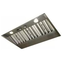
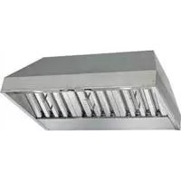
MAINTENANCE Proper maintenance of the Range Hood will assure proper performance of the unit. Grease Filters The grease filters should be cleaned fre- quently. Use a warm detergent solution. Grease filters are dishwasher safe. Remove filter by pushing filter towards the back of hood and rotating filter downward. Charcoal Filters The charcoal filters should be changed every 6 months. Rotate the filters to remove and replace. Hood Cleaning Stainless steel is one of the easiest materials to keep clean. Occasional care will help preserve its fine appearance. Cleaning tips:
- Hot water with soap or detergent is all that is usually needed.
- Follow all cleaning by rinsing with clear water. Wipe dry with a clean, soft cloth to avoid water marks.
- For discolorations or deposits that persist, use a non-scratching household cleanser or stainless steel polishing powder with a little water and a soft cloth.
- For stubborn cases, use a plastic scouring pad or soft bristle brush together with cleanser and water. Rub lightly in direction of polishing lines or "grain" of the stainless finish. Avoid using too much pressure which may mar the surface.
- DO NOT allow deposits to remain for long periods of time.
- DO NOT use ordinary steel wool or steel brushes. Small bits of steel may adhere to the surface causing rust.
- DO NOT allow salt solutions, disinfectants, bleaches, or cleaning compounds to remain in contact with stainless steel for extended periods. Many of these com- pounds contain chemicals which may be harmful. Rinse with water after expo- sure and wipe dry with a clean cloth. Painted surfaces should be cleaned with warm water and mild detergent only. GREASE FILTERS NON-DUCTED RECIRCULATION FILTER INSTALLATION
1. Position the filters over the blower.
2. Rotate to lock filters in place.
3. Purchase replacement filter packs
(contains 2) from your dealer. Part No. B03300487. CHARCOAL FILTERS- 10 - OPERATION Controls The hood is operated using the (4) push- buttons located at eye-level, on the front edge of the hood. The light switch turns the halogen lamps on and off. The blower on-low / off switch turns the blower on to its lowest running speed. The blower must be turned on using this switch. Turn the blower off by pressing this switch a second time. The blower medium speed switch changes the blower speed to medium. This switch works only if the blower is already running at low or high speed. The blower high speed switch changes the blower speed to high. This switch works only if the blower is already running at low or medium speed. The pilot lamp lights up whenever the blower is on. LIGHT SWITCH BLOWER ON-LOW / OFF SWITCH PILOT LAMP BLOWER MEDIUM SPEED BLOWER HIGH SPEED HALOGEN BULBS This range hood requires two halogen bulbs (Type T4, 12V, 20W).
1. Loosen the ring nut by turning it
2. Remove the bulb by pulling sideward (DO
3. Replace with Type T4, 12V, 20W halogen bulb. Do not touch replacement bulb
with bare hands! RING NUT FUSE REPLACEMENT SWITCH OFF THE ELECTRICITY SUPPLY. Remove the grease filters. Remove the electrical box support and open the fuse box. Replace with the same type of fuse (5x20mm, 4A, 125V). ELECTRICAL BOX SUPPORT FUSE- 11 -
BROAN ONE YEAR LIMITED WARRANTY
Broan warrants to the original consumer purchaser of its products that such products will be free from defects in materials or workmanship for a period of one year from the date of original purchase. THERE ARE NO OTHER WAR- RANTIES, EXPRESS OR IMPLIED, INCLUDING, BUT NOT LIMITED TO, IMPLIED WARRANTIES OR MERCHANT ABILITY OR FITNESS FOR A PAR- TICULAR PURPOSE. During this one-year period, Broan will, at its option, repair or replace, without charge, any product or part which is found to be defective under normal use and service. THIS WARRANTY DOES NOT EXTEND TO FLUORESCENT LAMP STARTERS, TUBES, HALOGEN AND INCANDESCENDT BULBS. This warranty does not cover (a) normal mainte- nance and service or (b) any products or parts which have been subject to misuse, negligence, accident, improper maintenance or repair (other than by Broan), faulty installation or installation contrary to recommended installa- tion instructions. The duration of any implied warranty is limited to the one- year period as specified for the express warranty. Some states do not allow limitation on how long an implied warranty lasts, so the above limitation may not apply to you. BROAN’S OBLIGATION TO REPAIR OR REPLACE, AT BROAN’S OPTION, SHALL BE THE PURCHASER’S SOLE AND EXCLUSIVE REMEDY UNDER THIS WARRANTY. BROAN SHALL NOT BE LIABLE FOR INCIDENTAL, CONSEQUENTIAL OR SPECIAL DAMAGES ARISING OUT OF OR IN CON- NECTION WITH PRODUCT USE OR PERFORMANCE. Some states do not allow the exclusion or limitation of incidental or consequential damages, so the above limitation or exclusion may not apply to you. This warranty gives you specific legal rights, and you may also have other rights, which vary from state to state. This warranty supersedes all prior warranties. To qualify for warranty service, you must (a) notify Broan at the address stated below or telephone: 1-800-637-1453, (b) give the model number and part identification and (c) describe the nature of any defect in the product or part. At the time of requesting warranty service, you must present evidence of the original purchase date. BEST BY BROAN, P.O. Box 140 Hartford, Wisconsin 53027 WARRANTY- 12 -
- B03300487 Non-ducted recirculation Filter Pack (Includes 2 filters)