
GXD 8 - Receiver QSC - Free user manual and instructions
Find the device manual for free GXD 8 QSC in PDF.
| Product Type | Audio Power Amplifier |
| Brand | QSC |
| Model | GXD 8 |
| Output Power (8 Ω) | 800 W per channel |
| Output Power (4 Ω) | 1200 W per channel |
| Maximum Power | 4500 W |
| Input Impedance | 20 kΩ (balanced or unbalanced) |
| Mains Power Supply | 100-240 V~, 50/60 Hz |
| Power Consumption | ~6.3 A - 3.6 A |
| Input Connectors | XLR female, 6.35 mm TRS jack, USB B |
| Output Connectors | NL4 (Neutrik SpeakON), binding posts |
| Digital Signal Processing (DSP) | Presets, equalizer, delay, limiter, filters |
| Indicators | CLIP, SIG, power (blue) |
| Display | LCD screen with adjustable contrast |
| Rack Mounting | Yes (screws not included) |
| Maintenance and Cleaning | Dry cloth only |
| Safety | Connect to earthed outlet, overvoltage protection |
| Repairability | Refer to an authorized QSC service center |
| General Information | Follow safety instructions and local codes |
Frequently Asked Questions - GXD 8 QSC
User questions about GXD 8 QSC
0 question about this device. Answer the ones you know or ask your own.
Ask a new question about this device
Download the instructions for your Receiver in PDF format for free! Find your manual GXD 8 - QSC and take your electronic device back in hand. On this page are published all the documents necessary for the use of your device. GXD 8 by QSC.
USER MANUAL GXD 8 QSC
EXPLANATION OF TERMS AND SYMBOLS
The term "WARNING!" indicates instructions regarding personal safety. If the instructions are not followed the result may be bodily injury or death.
The term "CAUTION!" indicates instructions regarding possible damage to physical equipment. If these instructions are not followed, it may result in damage to the equipment that may not be covered under the warranty.
The term "IMPORTANT!" indicates instructions or information that are vital to the successful completion of the procedure.
The term "NOTE" is used to indicate additional useful information.

The intent of the lightning flash with arrowhead symbol in a triangle is to alert the user to the presence of un-insulated "dangerous" voltage within the product's enclosure that may be of sufficient magnitude to constitute a risk of electric shock to humans.
The intent of the exclamation point within an equilateral triangle is to alert the user to the presence of important safety, and operating and maintenance instructions in this manual.

IMPORTANT SAFETY INSTRUCTIONS


WARNING: TO PREVENT FIRE OR ELECTRIC SHOCK, DO NOT EXPOSE THIS EQUIPMENT TO RAIN OR MOISTURE.
- Read these instructions.
- Keep these instructions.
- Heed all warnings.
- Follow all instructions.
- Do not use this apparatus near water.
- Clean only with a dry cloth.
- Do not block any ventilation opening. Install in accordance with the manufacturer's instructions.
- Do not install near any heat sources such as radiators, heat registers, stoves, or other apparatus (including amplifiers) that produce heat.
- Do not defeat the safety purpose of the polarized or grounding-type plug. A polarized plug has two blades with one wider than the other. A grounding type plug has two blades and a third grounding prong. The wide blade or the third prong are provided for your safety. If the provided plug does not fit into your outlet, consult an electrician for replacement of the obsolete outlet.
- Protect the power cord from being walked on or pinched particularly at plugs, convenience receptacles, and the point where they exit from the apparatus.
- Only use attachments/accessories specified by the manufacturer.
- Unplug this apparatus during lightning storms or when unused for long periods of time.
- Refer all servicing to qualified service personnel. Servicing is required when the apparatus has been damaged in any way, such as power-supply cord or plug is damaged, liquid has been spilled or objects have fallen into the apparatus, the apparatus has been exposed to rain or moisture, does not operate normally, or has been dropped.
- The appliance coupler, or the AC Mains plug, is the AC mains disconnect device and shall remain readily operable after installation.
- Adhere to all applicable, local codes.
- To prevent electrical shock, the power cord shall be connected to a mains socket outlet with a protective earthing connection.
- Consult a licensed, professional engineer when any doubt or questions arise regarding a physical equipment installation.
- Do not use any aerosol spray, cleaner, disinfectant or fumigant on, near or into the apparatus. Clean only with a dry cloth.
- Do not unplug the unit by pulling on the cord, use the plug.
- Do not submerge the apparatus in water or liquids.
- Keep ventilation opening free of dust or other matter.
TD-000449-00-D
TD-000449-00
Maintenance and Repair

WARNING! Advanced technology, e.g., the use of modern materials and powerful electronics, requires specially adapted maintenance and repair methods. To avoid a danger of subsequent damage to the apparatus, injuries to persons and/or the creation of additional safety hazards, all maintenance or repair work on the apparatus should be performed only by a QSC authorized service station or an authorized QSC International Distributor. QSC is not responsible for any injury, harm or related damages arising from any failure of the customer, owner or user of the apparatus to facilitate those repairs.
FCC Statement

NOTE: This equipment has been tested and found to comply with the limits for a Class B digital device, pursuant to Part 15 of the FCC Rules.
These limits are designed to provide reasonable protection against harmful interference in a residential installation. This equipment generates, uses and can radiate radio frequency energy and, if not installed and used in accordance with the instructions, may cause harmful interference to radio communications. However, there is no guarantee that interference will not occur in a particular installation. If this equipment does cause harmful interference to radio or television reception, which can be determined by turning the equipment off and on, the user is encouraged to try to correct the interference by one or more of the following measures:
- Reorient or relocate the receiving antenna.
- Increase the separation between the equipment and receiver.
- Connect the equipment to an AC outlet on a circuit different from that to which the receiver is connected.
- Consult the dealer or an experienced radio/TV technician for help.

NOTE: This Quick Start Guide is based on the basic configuration as the amplifier comes from the factory. For detailed instructions for custom configurations refer to the GXD User Manual.
Rack-Mount the Amplifier
Secure the amplifier in the rack with eight screws (not supplied), four in front, four in back. Typically, you will need a rear-ear mounting kit to mount the amplifier. Contact QSC Technical Services Group for more information about the kits. There are two different kits available. Follow the instructions included with the kit.
Connections
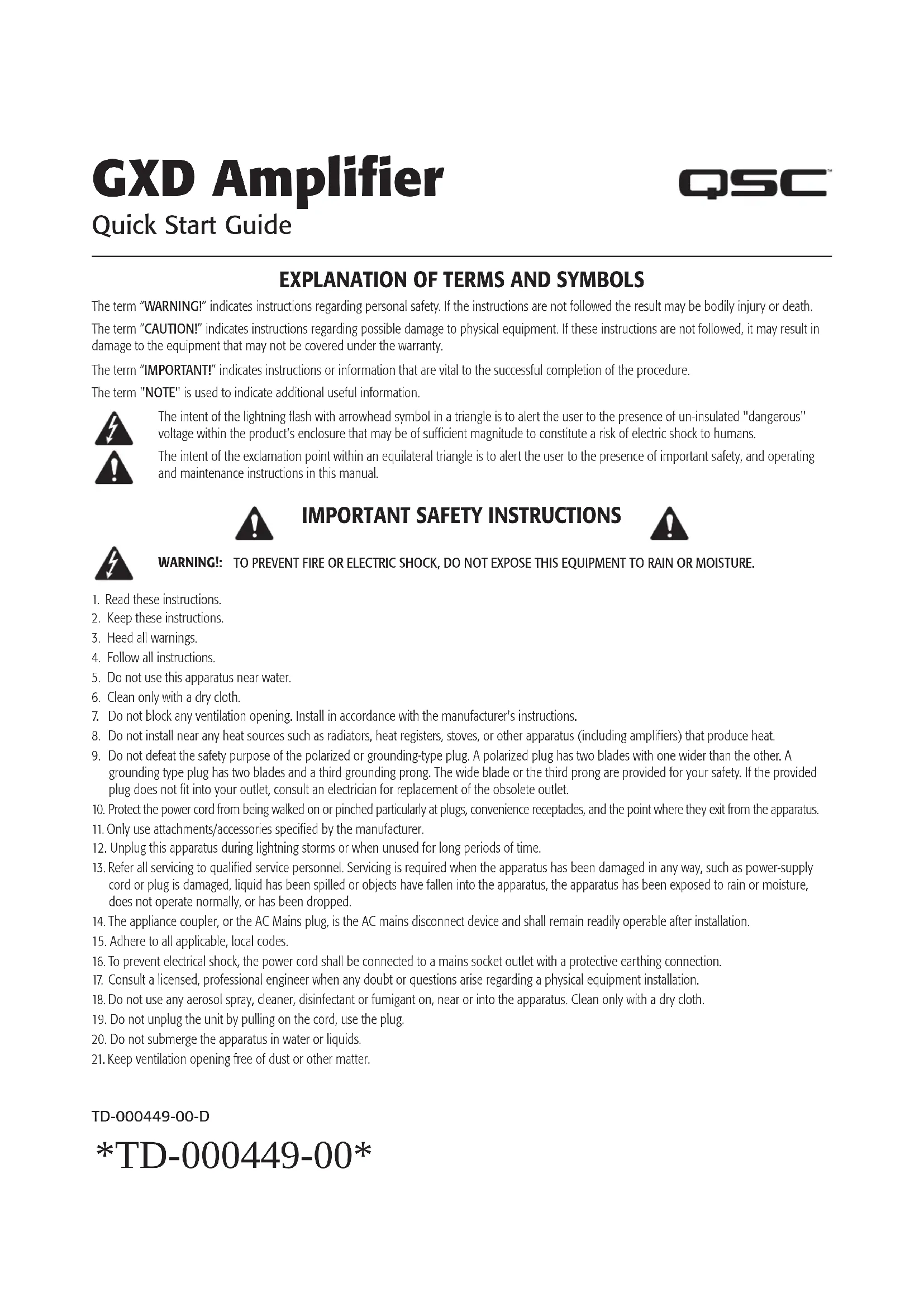
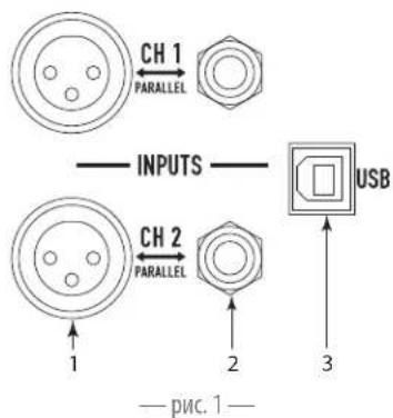
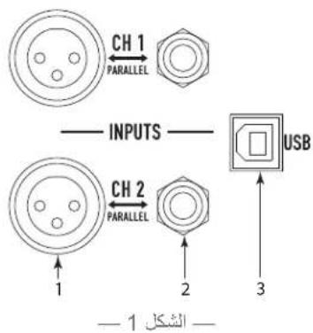
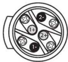
Inputs (Channels 1 & 2)
See Figure 1
Input Impedance: 20k Balanced, 10k Unbalanced See - Table 1 for wiring.
- XLR female
- 1/4'' female TRS Phone Jack
- USB Standard B connector - Used for updating the amplifier firmware, refer to the GXD User Manual for details.
Input Wiring
| Connector POS NEG GROUND | ||
| XLR 2 3 1 | ||
| 1/4" | TIP | RING |
| - Table 1 - | ||
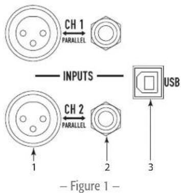
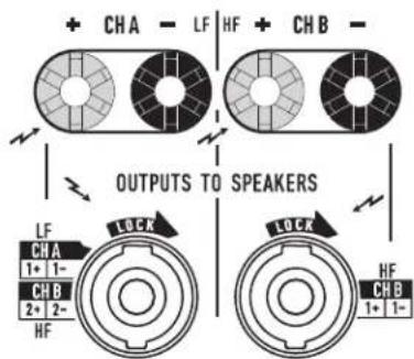
Outputs (Channels A & B)
See Figure 2
4Ω or 8Ω impedance
Power Output
| Amplifier 8Ω 4Ω Max Peak |
| GXD 4 400 W 600 W 1600 W |
| GXD 8 800 W 1200 W 4500 W |
| - Table 2 - |

CAUTION! Do not combine the audio outputs in any way. Do not connect the audio outputs to ground.
Wiring
Be sure to observe polarity.
- NL4 connector - See Figure 3
- Binding Posts - Use banana plugs or wire directly
AC Power
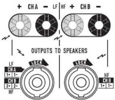
Male NL4 Wiring
Figure 3
EN

WARNING: The power cord shall be connected to a mains socket outlet with a protective earthing connection.
GXD4 Outputs
Figure 2
See Figure 4
Connect the IEC power cord to the AC receptacle on the rear of the amplifier.
Push to reset Breaker when necessary.
Power Consumption
-Table3-
| Amplifier | Voltage | Current | Frequency |
| GXD 4 | 100-240 VAC | ~3.3 A - 1.6 A | 50/60 Hz |
| GXD 8 | 100-240 VAC | ~6.3 A - 3.6 A | 50/60 Hz |
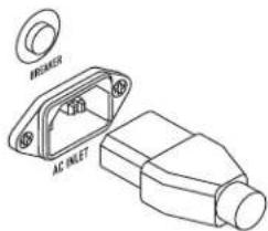
Figure 4
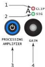
Controls and Indicators
See Figure 5
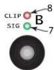
- Channel A CLIP indicator - illuminates red when the input is high enough to cause the channel to clip.
- Channel A SIG (signal) present indicator - illuminates green when there is a signal applied to the input.
- Power Switch/LED on/off - Illuminates blue when on.
- Adjust Channel A GAIN
- User Interface
a. HOME - go to HOME screen / view current PRESET
b. ENTER - select highlighted item and/or confirm parameter change
c. EXIT - return to previous screen and/or undo parameter change
- Adjust Channel B GAIN, selects and adjusts controls
- Channel B SIG (signal) present indicator - illuminates green when there is a signal applied to the input.
- Channel B CLIP indicator - illuminates red when the input is high enough to cause the channel to clip.
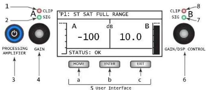
Figure 5
GXD Signal Flow
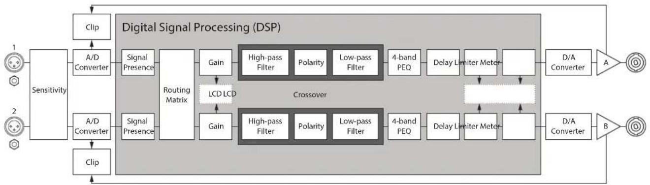
Figure 6
Setup and Operation
EN
Menu Tree
PRESET

PRESET RECALL
PRESET SAVE
PRESET SAVE AS
*STEREO DSP and DSP A / DSP B depend on the selected configuration.
STEREO DSP*
SENSITIVITY
CROSSOVER
EQ
DELAY
LIMITER
DSP A / DSP B*
SENSITIVITY
CROSSOVER
EQ
DELAY
LIMITER
UTILITIES
STATUS
CONTRAST
TIMEOUT
LOCKOUT
RESET
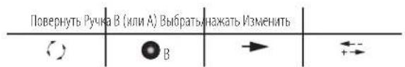
Navigation Key
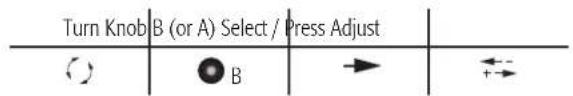
Figure 7
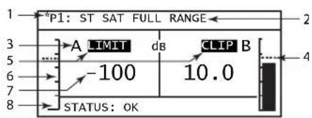
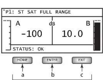
Home Screen
See Figure 8
From any screen HOME
- Asterisk (*) indicating an unsaved change to the Preset
- Currently active preset location (P1) and name
- Output channel letter A and B
- Limiter level indicator (Channels A and B)
- LIMIT and CLIP indicators
- Output meter A and B (visual)
- Output gain (digital) range = -100 to +10 dB (Channels A and B)
- Amplifier STATUS
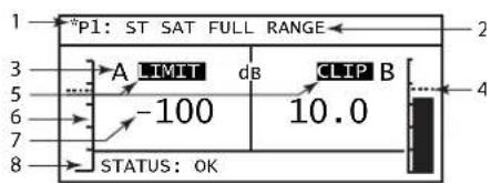
Figure 8
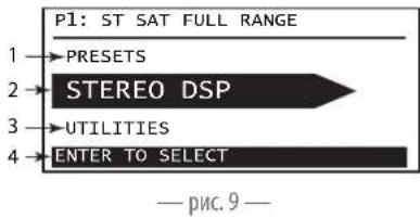
Main Navigation Menu
See Figure 9
From HOME ENTER
- Previous selection - PRESETS
- Currently selected -STEREO DSP (or DSP A and DSP B)
- Next selection - UTILITIES
- Instructions

Figure 9
Configurations
There are four basic types of configuration:
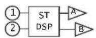
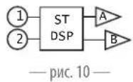
Figure 10
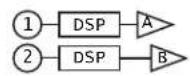
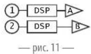
Figure 11
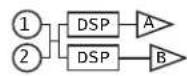
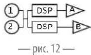
Figure 12
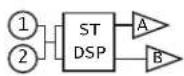
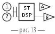
Figure 13
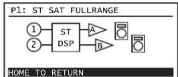
Figure 10 - 2-channels in, stereo DSP, 2-channels out - Channel controls are linked, audio signals are not combined. (P1 through P7)
Figure 11 - 2-channels in, separate DSP, 2-channels out - Channel controls are not linked except Sensitivity. (P8 through P10)
Figure 12 - 1 or 2-channels in (mono summing), separate DSP, 2-channels out - Channel controls are not linked except Sensitivity. (P11 through P18)
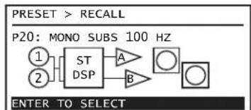
Figure 13 - 1 or 2-channels in (mono summing), stereo DSP, 2-channels out - Channel controls are linked, audio signals are combined. (P19 and P20) The configurations are selected using the presets. Refer to the GXD User Manual for details of all 20 available configurations.
PRESETS
A preset configures the inputs and outputs, along with setting the DSP. When you make changes to the DSP, you can save your setup in any of the 20 preset locations.
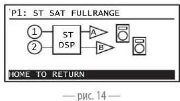
View Current Preset Configuration
From HOME HOME
To return HOME
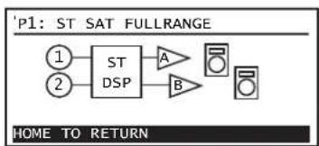
Figure 14
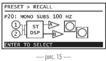
PRESETRECALL
Recall a preset to configure the amplifier to meet the requirements of your loudspeakers and installation.
There are 20 Presets. See Figure 15
1.From HOME ENTER
2. B PRESET
3. RESB-RECALL
4. B The pre-set you want,
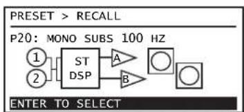
Figure 15
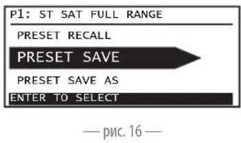
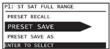
PRESET SAVE
Saves the active preset with any DSP changes. See Figure 16
1.From HOME ENTER
2. RESH
3. B RESET SAVE, ENTER ENTER
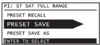
Figure 16
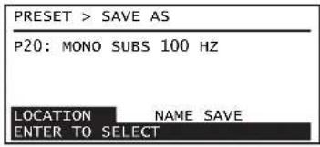
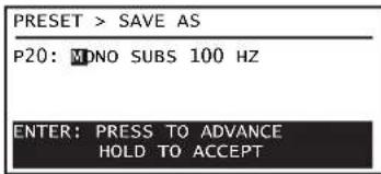
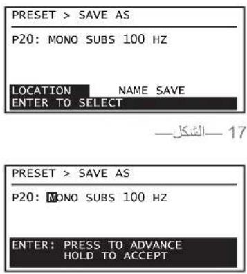
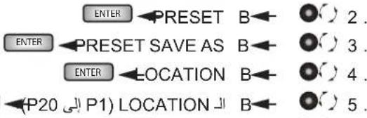
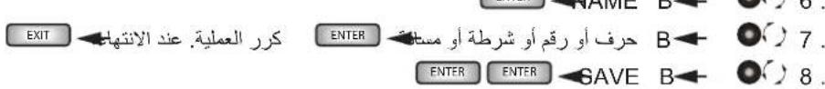
PRESET SAVE AS
Select the LOCATION and/or change the NAME to save changes you make to the DSP.
See Figure 17 and Figure 18
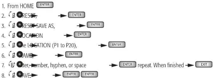
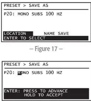
Figure 18
STEREO DSP or DSP A and DSP B
STEREO DSP is set for both channels equally, at the same time. Separate DSPs (DSP A and DSP B) are set independently for each channel. The Sensitivity controls are linked in both Stereo DSP and dual mono DSP. Switching between Stereo DSP and Separate DSP is done by recalling presets that are either stereo or dual mono.
Any changes you make are made in real time - you hear the change as it is being made.

NOTE: The term "STEREO DSP" is used in this document as a generic term to mean either STEREO DSP or DSP A/DSP B, unless specifically noted.
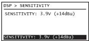
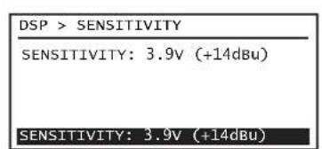
SENSITIVITY
See Figure 19
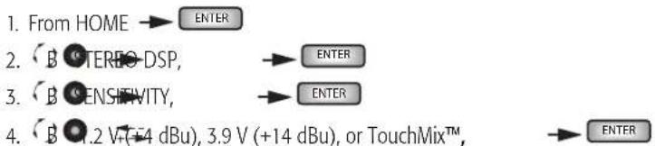
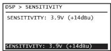
Figure 19
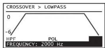
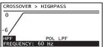
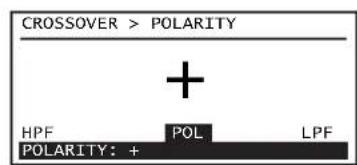
CROSSOVER and POLARITY
See Figure 20 through Figure 22.
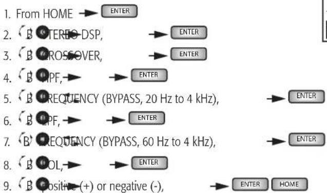

Figure 20
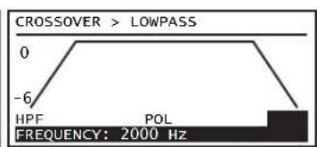
Figure 21
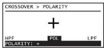
Figure 22
EQ
See Figure 23 through Figure 25.
1.From HOME ENTER
2. BOTEREODSP ENTER
3. B
4. B ANE, BAND2, BAND3, or BAND4
5. B GAIN: ENTER
6. (B) AIN(12 dB to +12 dB),
7. B FREQUENCY,
8. B FREQUENCY (20 Hz to 20 kHz),
9. B W (bandwidth),
10. B BANDWIDTH (0.1 Oct to 3.0 Oct),
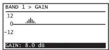
Figure 23
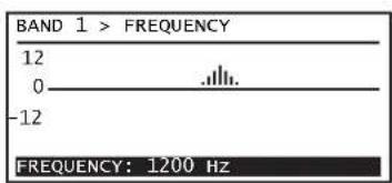
Figure 24
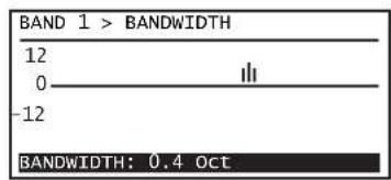
Figure 25
DELAY
See Figure 26
1.From HOME ENTER
2. BOTERBDSP, ENTER
3. B ELAT ENTER
4. ELAY0.00 to 56.30 FT, or 17.16 M, or 50 MS),

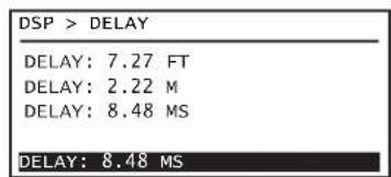
Figure 26
LIMITER
See Figure 27 and Figure 28.
1.From HOME ENTER
2. BOTEREODSP, ENTER
3. B D M I F E R
4. B TYPE
5. B MILD: MEDIUM, or AGGRESSIVE
6. B POWER ENTER
7. B POWER (see -Table 4), ENTER
8. B IMPEBANCE (4 Ω or 8 Ω), ENTER HOME
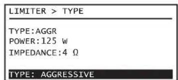
Figure 27
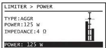
Figure 28
Model 4Ω8Ω
-Table4-
| GXD 4 | 5 W - 600 W 5 W - 400 W |
| GXD 8 | 5 W - 1200 W 5 W - 800 W |
Utilities
The following utilities are available on the GXD user interface. Refer to the GXD User Guide for details.
STATUS - Amplifier status including AMP TOTAL RUN TIME, HARDWARE version, and FIRMWARE version
CONTRAST - Sets the contrast of the front-panel LCD
TIMEOUT - Sets the time for the LCD to turn off. Using any control turns the LCD on.
LOCKOUT-LOCKDSP,LOCKALL,UNLOCK
RESET - Sets all amplifier parameters to the factory defaults, including all DSP parameters
QSC
Mailing Address:
QSC Audio Products, LLC
1675 MacArthur Boulevard
Costa Mesa, CA 92626-1468 USA
Telephone Numbers:
Main Number: (714) 754-6175
Sales & Marketing: (714) 957-7100 or toll free (USA only) (800) 854-4079
Customer Service: (714) 957-7150 or toll free (USA only) (800) 772-2834
Facsimile Numbers:
Sales & Marketing FAX: (714) 754-6174
Customer Service FAX: (714) 754-6173
World Wide Web:
www.qsc.com
E-mail:
info@qsc.com
service@qsc.com
tech_support@qsc.com
If you would like a full copy of the GXD User manual, visit the QSC Audio Products website at www.qsc.com
GXD8 5W-1200W 5W-800W
-Tabla4-
Utilidades
QSC Audio Products, LLC
1675 MacArthur Boulevard
If you would like a full copy of the GXD User manual, visit the QSC Audio Products website at www.qsc.com
| GXD 4 | 5 W - 600 W 5 W - 400 W |
| GXD 8 | 5 W - 1200 W 5 W - 800 W |
Tableau 4
Utilaires
QSC Audio Products, LLC
1675 MacArthur Boulevard
If you would like a full copy of the GXD User manual, visit the QSC Audio Products website at www.qsc.com
QSC Audio Products, LLC
1675 MacArthur Boulevard
Costa Mesa, CA 92626-1468 USA
Telefonnummern:
If you would like a full copy of the GXD User manual, visit the QSC Audio Products website at www.qsc.com
gwwqsc.com bll jc QSC Audio Products gagall gagall GXD alw yolal yolal yolal yolal yolal yolal yolal yolal yolal yolal yolal yolal yolal yolal yolal yolal yolal yolal yolal yolal yolal yolal yolal yolal yolal yolal yolal yolal yolal yolal yolal yolal yolal yolal
术语及符号说明
QSC Audio Products, LLC
1675 MacArthur Boulevard
Costa Mesa, CA 92626-1468 USA
电话号码:
总机:(714)754-6175
If you would like a full copy of the GXD User manual, visit the QSC Audio Products website at www.qsc.com
- P33bem XLR female.
- 14^ pa3bem female TRS.
- TaHapthb paBem USB Standard B nObl3yetra 06HOBnH MmKpnporpaMMHOro oecneHn ycmnten; nnoIpyeHn CbeHn 06patntc b k pykoBDCTby noIb3oBeTEn GXD.
Pacnka BXoDa
| Pazbeb MON. CTP3EMPA | ||
| XLR 231 | ||
| 1/4" KOH4K | KOH4O | ПИБ3A |
| —tablina 1— | ||
*STEREODSPMDSPA/DSPB3ABMCMOCTOT Bb6paHHOHKOFypaHIN.
STEREO DSP*
SENSITIVITY
CROSSOVER
EQ
DELAY
LIMITER
DSP A / DSP B*

SENSITIVITY
CROSSOVER
EQ
DELAY
LIMITER
UTILITIES
STATUS
CONTRAST
TIMEOUT
LOCKOUT
RESET
—pnc.7—
EeCTBn
Eomashn3kpan
CM.pnc.8
CnH6oTo3KpaHa HOME
1.3Be3dOuaKa (^*) 0603HauaET HecoXpaHeHHoe H3MeHeHMe BHaCTpOKe
2. TextушeeakTINBHOENIOXeHMeHCTpOKN(P1)IIMM
3.БукьыканаывхдаAиВ
4.Индкатуpoьнллмпета(kaHbI A B)
5. MнДикаТоры LIMIT n CLIP
6. HNikatop BbIXoB0A N B (Bn3aynbH)
7.ДианэзунусileнгьаHa bbyxoDE(mФpoBOB)=OT MMHyc 100do nno1o 10 n5(kaHnblA uB)
8. CoctoHme (STATUS) ycnnten
—pnc.8—
TnaBHOe MeHIO HABINaUN
CM.PMC.9
HaekpaeHOME ENTER
- Pnpdyuuee BdueneHne PRESETS (npdyctaHOBk)
- Tekyuee BvdueneHne STEREO DSP (mN DSP A uDSP B)
3.Cnnyuuee BbIeHneHne UTILITIES (yTmnt)
4.Мнчтукши
KoHΦnHypaun
IMeKOTc TaetbIpe OCHOBbIX TMn KOHmYpaunM.
Pc.10-2 KaHana Ha BxOe,crepeo DSP,2 KaHana Ha BixOe - oprahbl npabneHHa KaHAnom o6bEHNbHa ayDIOOM HbBbOaTc pa3dEbnO (ot P1 do P7).
PnC.11-2 KaHana Hb Xdoe, pa3dienbHbe DSP, 2 KaHana Hb Bixdoe - opraHb ynpabEnHa KaHano p3dienhBi (KpOme UyBHTBnEHOCTn [Sensitivty]) (ot P8 do P10).
Pc.12-1nn 2 KaHana Ha Bxode (MoHocymmpoBaHne),pa3deneBhie DSP,2 KaHana Ha BbXode -opraHbI ynpabEnHa KaHAnom pa3deneHbI (KpOme «UyBCTBntenbHOCTN) (Sensitivity) (ot P11do P18).
Pc.13-1nn2 KaHana Ha Bxode (MOHCyMMMPOBaHne), crepeo DSP, 2 KaHana Ha BbXode -opraHbI ynpaBHeHa KaHAnom o6beJHHe, ayIMOnHnBIs o6beJHHe (P19 n P20).
KoHpyaunBbupauTc nnonoukb npdyctahOBok. IpaonnyeHnHphiopMaun 60bcx20octyHbX npdyctahOBkax, 6paatntecb KGD pykoBDCTBy noIb3oBaTeR.
PRESETS (PpeyctaHOBKn)
PpeyctahOBKn onpepeenrIOT paOby BxoIOB n BbXIOB, a TAKKe npaMeTpB DSP. PnM3MeHmHnpaMeTPOB DSP M0KHO coxpaHtB HAcTpoKN b Nk6oBn 20 peyeCTAHOBOK.
PpocmoTp Tekyuee konhoIpyaun npedyctaHOBOK
Haekpahe HOME HOME
HOME
PRESETRECALL(Bb6opnpedyctahOBKn)
Bb6op npdyctahOBKn, co0TBeCTBykoien npapMetpam rpoMKorOBopntenen m nx paioIOxKeHIO. DocTyHHb 20 npdyctahOBok.
CM.pmc.15
1.HaKpaHEHOME ENTER
2. SET{BpnyctaHOBka},
3. SETRECALL(Bb6bpnpdyctaHOBku)
4. B. TaemnmpedyctahOBka,
PRESET SAVE (CoxpaHntb npedyctaHOBky)
CoxpaHReTAKTHBHyN ppeyctahOBky CIOb6mM N3MeHeHMMDSP.Cm.pnc.16
- Ha ekpahe HOME ENTER
- TET(8peneyctahOBka),
- B.ETETWE (CoXpaHnHTb npedyctaHOBky),
PRESET SAVE AS (CoxpaHnTb npedyctaHOBky KaK)
Bb6ephtpe paonolokhenie (LOCATION) m/ma n3MeHnTe MMA (NAME) dna coxpaHeHHN 3MeHeHHN B DSP.
CM.pnc.17 npnc.18
- Naэкpane HOME
- 1
- SET-SAVE AS (coxpaHn
4.LATI(Pacnonoxenne) - LATIG (pactioxkeHne oT P1doP20)
- B N M F (mm)
- 8.0,23a,14ppa,depcn nnn npo6en
- 3xHf(GpaHHTb)


-pmc.17
-pmc.18
STEREO DSP nnn DSP A n DSP B
STEREO DSP yctahabnBaetca onHOBpeMeHHo 10a o60x KaHaoB. OteIbHbE DSP (DSP A n DSP B) ycTaHaBnBaHOTc H3aBNCMO dKaKdo KAHana. OprAh b npabneHryBCTBHeNtbo 06beJInHeB b Stereo DSP u DBOHOM mono DSP. PepeknueHme MeXy pexmmAstero DSP n Separate DSP ocuyectbnerc c nmoio bblopa npedytaHOBC pexmMOM CTEeO WIN DBOHOe MOHO.
Bce m3MeHHeI npOxOJAT BpeaJIbHOM BpemeHn —— Bbl MoXeTe cpa3y ux ycJIbIIaTb.

PIMMEAHHE: TepMNSTEREO DSP, nionb3yemn B 20m DOkymeHT, ABnETcO6uM TepMNHom M MoKeT O63HaATb MN STEREO DSP, mN DSP A/DSP B, eCNHtoc6bxyK3aHm.
RU
SENSITIVITY (yBCTbUTeJIbHOCTb)
CM.pmc.19
- Načkpane HOME
- B
- 5
- V (+14 dBu), 3.9 V (+14 dBu) nmu TouchMixTM,

-pmc.19
CROSSOVER (KpoccoBep) n POLARITY (Poiarphoctb)
KoMaNaHmQ SsC Audio Products, LLC
1675 MacArthur Boulevard
Costa Mesa, CA, 92626-1468, CUIA
TenefoHbI
OCHOBHOMeP: (714) 754-61-75
PpdaJHmApKeTnH: (714) 957-71-00 mnn 6ecnntbHm Homep (TOnbKO dIa Cua) (800) 854-40-79
Cnykba KneHcTckoi noDepKnn: (714) 957-71-50 mNbeCnIaTHbI HmOpE (ToIbKO nIa CIIIA) (800) 772-28-34
Homepa akcoB
QakcOTJeIaMapKeTnHaI npOaJk: (714) 754-61-74
0aKcIyJbKJIeHtCKoI npJepeKKn: (714) 754-61-73
A.ДресВИnteРсЕТС:
www.gsc.com
JnKtpponHna noHa:
info@qsc.com
service@qsc.com
tech_support@qsc.com
If you would like a full copy of the GXD User manual, visit the QSC Audio Products website at www.qsc.com
gwwqsc.com bll jc QSC Audio Products gagall gagall GXD alw yolal yolal yolal yolal yolal yolal yolal yolal yolal yolal yolal yolal yolal yolal yolal yolal yolal yolal yolal yolal yolal yolal yolal yolal yolal yolal yolal yolal yolal yolal yolal yolal yolal yolal
jagglgclalaa
a 1
g 11111111111111111111111111111111111
j 1
aagall aalil 1000 (alao) "NOTE"
gaiiie 1j 1 j 1 j 1 j 1 j 1 j 1 j 1 j 1 j 1 j 1 j 1 j 1 j 1 j 1 j 1 j 1 j 1 j 1 j 1 j 1 j 1 j 1 j 1 j 1 j 1 j 1 j 1 j 1 j 1 j 1 j 1 j 1 j 1 j 1 j
J 1
Jdall aagaaagaaagaaagaaagaaagaaagaaagaaagaaagaaagaaagaaagaaagaaagaaagaaagaaagaaagaaagaaagaaagaaagaaagaaagaaagaaagaaagaaagaaagaaagaaagaaagaaagaaagaaagaaagaaagaaagaaagaaagaaagaaagaa


aayuulagaa

:WARNING!

7
1
2
3
4
5
6
7
8
aannnnn nnnnnnnnnnnnnnnnnnnnnnnnnnnnnnnnnnnnnnnnnnnnnnnnnnnnnnnnnnnnnnnnnnnnnnnnnnnnnnnnnnnnnnnnnnnnnnnnnnn
jell llll jll llllllllll 10
Laiiaaiaaaas yalal aai gll lalal/laalalal.11
12
13
jglal jglal jglal jglal jglal jglal jglal jglal jglal jglal jglal jglal jglal jglal jglal jglal jglal jglal jglal jglal jglal jglal jglal jglal jglal jglal jglal jglal jglal jglal jglal jglal jglal jglal j
a a
14
.15
.16
a aaa a a a a a a a a a a a a a a a a a a a a a a a a a
GXD

Jalal
a a a a a a a a a a a a a a a a a a a a a a a a a a a a a a a a a
它恰好 a ≤ b ≤ c 或 a ≥ b 且 c

(2)1
155
1 10jglg20:
TRS 1% .2
JGXD 1000000000000000000000000000000000000000000000000000000000000000
| 1 | 3 | 2 | XLR |
| a | a | a | a |
| -1 | -1 | - |
a
| öjörderliche | p514 | p518 | GXD 4 |
| 1,1600 | 1,1600 | 1,1600 | GXD 8 |
| 1,4500 | 1,4500 | 1,4500 | GXD 8 |
-2J
(gj)
2.5.1.1
8 4
Cgall jy
:CAUTION!

Male NL4 Wiring
3
GXD4 Outputs
-2
#
3JS-NL4
·dill
0
JSSA 1
aai jia jia jia jia jia jia jia jia jia jia jia jia jia jia jia jia jia jia jia jia jia jia jia jia jia jia jia jia jia jia jia jia jia jia jia jia jia jia jia jia jia jia jia jia jia jia jia jia jia

- 5,1 , 5,1 , 5,1

-4J
S_ OBC = S_ ABC + S_ COD
-3J
IEC 89 1000000000000000000000000000000000000000000
aalil 1 jill lal
Cui jia gai gao zai li
5
5User Interface
-5
GAIN/DSP CONTROL
1
aill lal y Lg y g y
a o j 123456789011234567890123456789012345678901234567890123456789012345678901234567890123456789012345678901234567890123456789
j jy bie jz jy 1 LED/2iia i /Jae .3
Joull
4.
- pssuaa
a a a a a a a a a a a a a a a a a a a a a a a a a a a
a
i 1
ylll lal 15
14J.S.
y
HOME
HOME
Saaee
-15
20 2y. yai aalll g jll galeaill cialiaol gail laoai aai aai ai ae iie
- k z( 1) jbjj,jbj, z_zz = 2k + 1
ENTER
1.
ENTER
PRESET
2.
ENTER
PRESET RECALL
B
()3.
ENTER
ENTER
yji yj
B
4.
16
16 1
ENTER
aaiii 1.
ENTER
PRESET
B
2.
ENTER
ENTER
PRESET SAVE
B
3.
18
S gann 1100y
18 17
ENTER
DSP DSP STEREODSP
S 150
aaii i aaii
DSP/ DSP STEREODSP la pae "STEREODSP"
TEA
A
19
a
19.5.2.1
ENTER
ENTER STEREODSP B2
ENTER SENSITIVITY B 3.
ENTER TouchMixTM 3.9 12 B
—21
20
a bail g jil
.22 20
ENTER
ENTER STEREODSP B2.
ENTER GROSSOVER B 3.
ENTER HPF B 4.
22
QSC Audio Products, LLC
1675 MacArthur Boulevard
Costa Mesa, CA 92626-1468 USA
:
(714) 754-6175:
(714)957-7100:
(800) 854-4079 (
(714)957-7150:xxaiia
(800) 772-2834 (baa aasaaal
:U
(714) 754-6174:
(714) 754-6173: cnaal 2022 wsl
aall jyj 4
www.qsc.com
1
info@qsc.com
service@qsc.com
tech_support@qsc.com
If you would like a full copy of the GXD User manual, visit the QSC Audio Products website at www.qsc.com