
RKB850 V2 - Receiver ROTEL - Free user manual and instructions
Find the device manual for free RKB850 V2 ROTEL in PDF.
| Product type | Eight-channel power amplifier |
| Brand | Rotel |
| Model | RKB850 V2 |
| Output power | 50 W/channel (8 channels driven, 20 Hz - 20 kHz, < 0.1% THD, 8 ohms) |
| Total harmonic distortion | < 0.08% (20 Hz - 20 kHz, 8 ohms) |
| Damping factor | > 150 |
| Input impedance | 100 kOhms |
| Input sensitivity | 0.6 V |
| Amplifier gain | 30 dB |
| Frequency response | 20 Hz - 20 kHz, +0 dB / -1.4 dB |
| Signal-to-noise ratio (IHF A) | 108 dB |
| Channel separation | > 60 dB |
| Speaker impedance | 4 ohms minimum |
| Power supply | 120 V, 60 Hz (United States) / 230 V, 50 Hz (Europe) |
| Power consumption | 150 W (operating), 40 W (idle), < 0.5 W (standby) |
| Dimensions (W x H x D) | 430 x 97 x 424 mm |
| Net weight | 9.3 kg |
| Main features | RCA inputs, digital optical inputs, 12V trigger, RS-232 link, level control, mono mode, daisy-chaining, cooling fans |
| Maintenance and cleaning | Clean with a dry cloth or vacuum. Do not use any liquids. |
| Safety | Do not open the unit. Unplug during storms or extended non-use. Follow ventilation and installation instructions. |
| Spare parts and repairability | Contact a Rotel authorized repair center. Do not attempt repairs yourself. |
| General information | Eight-channel power amplifier designed for audiophile use. Manufacturer's warranty provided upon returning the registration card. |
Frequently Asked Questions - RKB850 V2 ROTEL
User questions about RKB850 V2 ROTEL
0 question about this device. Answer the ones you know or ask your own.
Ask a new question about this device
Download the instructions for your Receiver in PDF format for free! Find your manual RKB850 V2 - ROTEL and take your electronic device back in hand. On this page are published all the documents necessary for the use of your device. RKB850 V2 by ROTEL.
USER MANUAL RKB850 V2 ROTEL
Eight Channel Power Amplifiers
Important Safety Instructions
Notice
The RS232 connection should be handled by authorized persons only.
WARNING: There are no user serviceable parts inside. Refer all servicing to qualified service personnel.
WARNING: To reduce the risk of fire or electric shock, do not expose the unit to moisture or water. Do not expose the unit to dripping or splashing. Do not place objects filled with liquids, such as vases, on the unit. Do not allow foreign objects to get into the enclosure. If the unit is exposed to moisture, or a foreign object gets into the enclosure, immediately disconnect the power cord from the wall. Take the unit to a qualified service person for inspection and necessary repairs.
Read all the instructions before connecting or operating the component.
Keep this manual so you can refer to these safety instructions.
Heed all warnings and safety information in these instructions and on the product itself. Follow all operating instructions.
Clean the enclosure only with a dry cloth or a vacuum cleaner.
Do not use this unit near water.
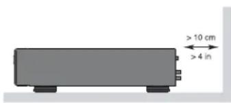
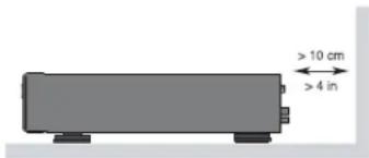
You must allow a minimum 10 cm or 4 inches of unobstructed clearance around the back of the unit.
Do not place the unit on a bed, sofa, rug, or similar surface that could block the ventilation openings. If the unit is placed in a bookcase or cabinet, there must be ventilation of the cabinet to allow proper cooling.
Keep the component away from radiators, heat registers, stoves, or any other appliance that produces heat.
WARNING: The rear panel power cord connector is the mains power disconnect device. The device must be located in an open area that allows access to the cord connector.
The unit must be connected to a power supply only of the type and voltage specified on the side panel. (USA: 120 V/60Hz, EC: 230V/50Hz)
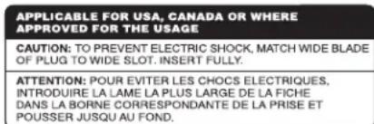
Connect the component to the power outlet only with the supplied power supply cable or an exact equivalent. Do not modify the supplied cable. A polarized plug has two blades, with one wider than the other. A grounding plug has two blades plus a third grounding prong. These are provided for your safety. Do not defeat grounding and/or polarization safety provisions. If the supplied plug does not fit your outlet, please consult an electrician for replacement of the obsolete outlet. Do not use extension cords.
The main plug of the power cordset is a disconnect device of the apparatus. In order to completely disconnect the apparatus from the supply mains, the main plug of the power cordset should be unplugged from the mains (AC) outlet. The power LED indicator will not be lit up to show the power cord is unplugged. The disconnect device shall remain readily operable.
Do not route the power cord where it will be crushed, pinched, bent, exposed to heat, or damaged in any way. Pay particular attention to the power cord at the plug and where the cord exits the back of the unit.
The power cord should be unplugged from the wall outlet during a lightning storm or if the unit is to be left unused for a long period of time.
This apparatus shall be connected to a main socket outlet with a protective earth connection.
Use only accessories specified by the manufacturer.
Use only with a cart, stand, rack, bracket or shelf system recommended by Rotel. Use caution when moving the unit in a stand or rack to avoid injury from a tip-over.
Use Class 2 wiring for speaker connections to ensure proper installation and minimize the risk of electrical shock.
Immediately stop using the component and have it inspected and/
or serviced by a qualified service agency if:
The power supply cord or plug has been damaged.
- Objects have fallen or liquid has been spilled into the unit.
- The unit has been exposed to rain.
- The unit shows signs of improper operation.
- The unit has been dropped or damaged in any way.


Rotel products are designed to comply with international directives on the Restriction of Hazardous Substances (RoHS) in electrical and electronic equipment and the disposal of Waste Electrical and Electronic Equipment (WEEE). The crossed wheelie bin symbol indicates compliance and that the products must be appropriately recycled or processed in accordance with these directives.

Figure 1: Controls and Connections
Figure 1: Commandes et branchements
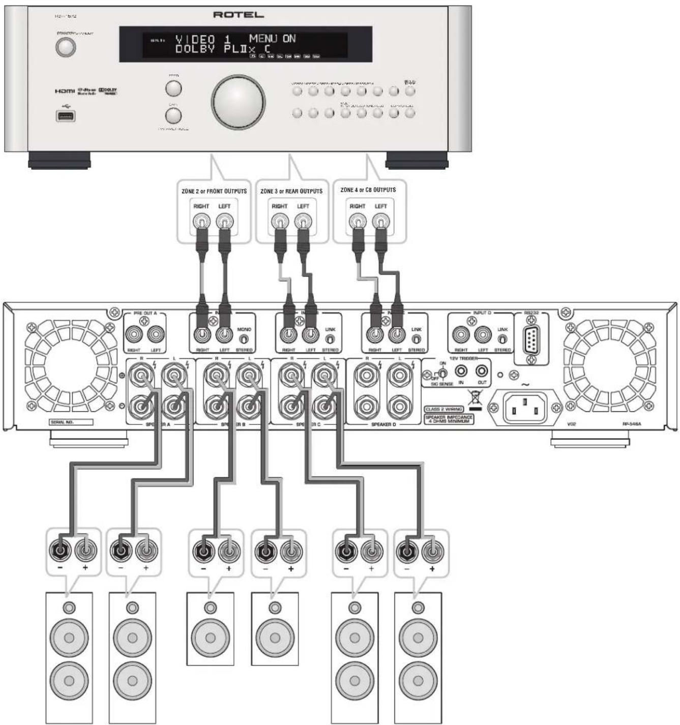
Figure 2: Hook-up Illustration
Important Notes
When making connections be sure to:
Turn off all the components in the system before hooking up any components, including loudspeakers.
Turn off all components in the system before changing any of the connections to the system.
It is also recommended that you:
Turn the volume control of the amplifier all the way down before the amplifier is turned on or off.
Remarques importantes
Important Safety Instructions 2
Figure 1: Controls and Connections 3
Figure 2: Hook-up Illustration 4
Important Notes 5
About Rotel. 6
A Word About Watts 6
Getting Started 6
A Few Precautions 7
Placement 7
AC Power and Control 7
AC Power Input 7
POWER Switch and Power Indicator 7
Trigger Mode Selector 7
12V Trigger Input and Output 7
Protection Indicator 8
Signal Connections 234 8
RCA Inputs 8
Linking the Inputs 8
Mono Switch 4 8
Input Level Controls 8
Preamp Output 8
Optical Inputs 8
Speaker Outputs 9
Speaker Selection 9
Speaker Wire Selection 9
Polarity and Phasing 9
Speaker Connections 9
RS232 Connector 9
Cooling Fans 9
Troubleshooting 9
Power Indicator Is Not Illuminated 9
No Sound 9
Power Indicator Is Blinking 9
Specifications 10
About Rotel
Our story began over 50 years ago. Over the decades, we have received hundreds of awards for our products and satisfied hundreds of thousands of people who take their entertainment seriously - like you!
Rotel was founded by a family whose passionate interest in music led them to manufacture high-fidelity components of uncompromising quality. Through the years, that passion has remained undiminished and the family goal of providing exceptional value for audiophiles and music lovers, regardless of their budget, is shared by all Rotel employees.
Rotel's engineers work as a close team, listening to, and fine tuning, each new product until it reaches their exacting musical standards. They are free to choose components from around the world in order to make that product the best they can. You are likely to find capacitors from the United Kingdom and Germany, semiconductors from Japan or the United States, while toroidal power transformers are manufactured in Rotel's own factory.
We all have concerns about our environment. And, as more and more electronics are produced it is especially important for a manufacturer to do all it can to engineer products that have a minimum impact on the environment.
At Rotel, we are proud to do our part. We have reduced the lead content in our products by using special lead-free ROHS solder and components. Our engineers continually strive to improve power supply efficiency without compromise to quality. When in standby mode Rotel products use minimal power to meet global Standby Power Consumption requirements.
The Rotel factory is also doing their part to help the environment through constant improvements to product assembly methods for a cleaner and greener manufacturing processes.
All of us at Rotel thank you for buying this product. We are sure it will bring you many years of enjoyment.
A Word About Watts
The RKB-850 and RKB-D850 power output is quoted as 50 watts for each channel, while the RKB-8100 and RKB-D8100 is 100 watts when all eight channels are operating together at full power.
Rotel has chosen to specify the power output in this way because, in Rotel's experience, it gives the truest value of the receiver or amplifier's power capability.
When comparing specifications for different products, you should be aware that power output is often specified in other ways, so you may not be comparing like with like. For example, the power output may be quoted with only one channel operating, giving a higher maximum figure.
A loudspeaker's impedance rating indicates the electrical resistance or load it offers when connected to the amplifier, usually 8 ohms or 4 ohms. The lower the impedance, the more power the speaker will need. In effect, a 4 ohm speaker will require twice as much power as an 8 ohm speaker.
However, Rotel amplifiers are designed to work into any speaker impedance between 8 and 4 ohms, and with all the channels working up to their full power. Because the Rotel design is optimized for use with all channels operating together, Rotel is able to specify the true power output for both channels.
This can be important for your enjoyment, too. When watching movies, it's nice to have the amplifier able to reproduce full power into all the channels at the same time, especially in the case of a volcano exploding!
Getting Started
Thank you for purchasing the Rotel RKB Series Eight Channel Power Amplifier. When used in a high-quality music audio system, your Rotel product will provide years of musical enjoyment.
The RKB amplifiers are high-power amplifiers, providing the highest level of audio performance. A massive power supply, premium components, and Rotel's Balanced Design ensure superb sound quality. High current capability allow the amplifiers to drive the most demanding loudspeakers.
Be aware that the RKB amplifiers are capable of high levels of output power. Make sure that your speakers can handle the power of the amplifier. If in doubt about your speakers, ask your local Rotel audio dealer for advice.
These amplifiers are straightforward in their installation and operation. If you have experience with other stereo power amplifiers, you shouldn't find anything perplexing. Simply plug in the associated components and enjoy.
A Few Precautions
WARNING: To avoid potential damage to your system, turn off ALL the components in the system when connecting or disconnecting the loudspeakers or any associated components. Do not turn the system components back on until you are sure all the connections are correct and secure. Pay particular attention to the speaker wires. There must be no loose strands that could contact the other speaker wires, or the chassis of the amplifier.
Please read this manual carefully. In addition to basic installation and operating instructions, it provides valuable information on various RKB amplifier system configurations as well as general information that will help you get optimum performance from your system. Please contact your authorized Rotel dealer for answers to any questions you might have. In addition, all of us at Rotel welcome your questions and comments.
Save the RKB amplifier shipping carton and all enclosed packing material for future use. Shipping or moving the amplifiers in anything other than the original packing material may result in severe damage to your amplifier.
If included in the box please fill out and send in the owner's registration card. Also be sure to keep the original sales receipt. It is your best record of the date of purchase, which you will need in the event warranty service is ever required.
Placement
The RKB amplifiers generate heat as part of their normal operation. The heat sinks and ventilation openings in the amplifier are designed to dissipate this heat. The ventilation slots in the top and bottom covers must be open. When possible there should be 10cm (4 inches) of clearance around the back side of the chassis. Reasonable airflow in the equipment rack is required to prevent the amplifier from overheating.
Remember the weight of the amplifier when you select an installation location. If you are not using the included rack ears make sure that the shelf or cabinet used can support the RKB. We recommend installing the unit in furniture designed to house audio components. Such furniture is designed to reduce or suppress vibration which can adversely affect sound quality. Ask your authorized Rotel dealer for advice about component furniture and proper installation of audio components.
AC Power and Control
AC Power Input
Your amplifier is configured at the factory for the proper AC voltage in the country where you purchased it, either 120 volts or 230 volts. The AC line configuration is noted on a label on the side panel.
NOTE: Should you move your unit to another country, it may be possible to reconfigure it for use on a different line voltage. Do not attempt to perform this conversion yourself. Opening the enclosure of the unit exposes you to dangerous voltages. Consult a qualified service person or the Rotel factory service department for information.
NOTE: Some products are intended for sale in more than one country and as such are supplied with more than one AC cord. Please only use the one appropriate for your country/region.
Because of its high power rating, the amplifier can draw considerable current. Therefore, it should be plugged directly into a wall outlet. The RKB amplifier must be plugged into a 3-pin polarized outlet. Do not use an extension cord. A heavy duty multi-tap power outlet strip may be used if it (and the wall outlet) is rated to handle the current demanded by the amplifier and all the other components connected to it.
Be sure the POWER SWITCH 1 on the front panel of the amplifier is turned off (in the "out" position). Then, connect the supplied power cord to the Power Connector 2 on the rear of the unit and the AC power outlet.
If you are going to be away from home for an extended period of time such as a month-long vacation, it is a sensible precaution to unplug your amplifier (as well as other audio and video components) while you are away.
POWER Switch and Power Indicator
The power switch is located on the front panel of your amplifier. To turn the amplifier on, push the switch in. The ring around the switch will light up and blink three times, indicating that the amplifier is turned on. To turn the amplifier off, push the button again and return it to the "out" position.
NOTE: Place the self adhesive ring over the light surrounding the power switch if the blue light is too bright.
Trigger Mode Selector
The RKB amplifiers provide three different options for manual or automatic power operation. These modes are selectable using a three-position switch on the back panel as follows:
- With the switch in the OFF position, the amplifier is turned on or off manually using the front panel power switch. Also use this mode if you are using a switched AC outlet to control power to the amplifier.
- With the switch in the SIGNAL SENSE position, the amplifier turns on automatically when an audio signal is detected at the inputs. The amplifier will go into Signal Sense Standby mode and the front Power Indicator will dim after approximately 10 minutes without detecting an audio signal. The front panel POWER SWITCH overrides this function. It must be ON for the signal sensing function to operate. Turning the front panel power switch OFF turns the amplifier off, regardless of whether or not a signal is present.
- With the switch in the ON position, the amplifier is turned on automatically when a 12 volt trigger signal is present at the 3.5mm jack of TRIGGER IN on the rear panel. The amplifier will go into standby mode and the front Power Indicator will dim if the +12 volt signal is not present. The front panel POWER SWITCH overrides this function. It must be ON for the +12V trigger to work. Turning the switch OFF turns the amplifier off, regardless of whether or not a trigger signal is present.
12V Trigger Input and Output
The jack labeled IN is for connecting the 3.5mm mono plug/cable carrying a +12 volt trigger signal to turn the amplifier on and off. To use this feature the toggle switch must be set to the ON position. This input accepts any control signal (AC or DC) ranging from 3 volts to 30 volts.
The jack labeled OUT is for connecting another 3.5mm mono plug/cable to provide a 12 volt trigger signal to other components. The 12 volt output signal is available whenever a +12 volt trigger signal is applied to the IN connector.
NOTE: The maximum current for the trigger out is 10mA.
Protection Indicator
The RKB amplifiers feature thermal and over-current protection circuits that protect against potential damage in the event of extreme or faulty operating conditions.
Most likely, you will never see this protection circuitry in action. However, should a faulty condition arise, the amplifier will shut down and the Power Indicator on the front panel will be blinking.
If this happens, turn the amplifier off, let it cool down for several minutes, and attempt to identify and correct the problem. When you turn the amplifier back on, the protection circuit will automatically reset and the Power Indicator should light up, indicating that the amplifier is operating normal.
In most cases, the protection circuitry activates because of a fault condition such as shorted speaker wires, or inadequate ventilation leading to an overheating condition. In very rare cases, highly reactive or extremely low impedance speaker loads could cause the protection circuit to engage.
If the protection circuitry triggers repeatedly and you are unable to isolate and correct the faulty condition, contact your authorized Rotel dealer for assistance in troubleshooting.
Signal Connections 234
See Figure 2
NOTE: To prevent loud noises that neither you nor your speakers will appreciate, make sure the system is turned off when you make any signal connections.
The RKB amplifier provides standard RCA type input connections as found on nearly all audio equipment.
In addition to the four groups of stereo inputs labeled INPUT A to INPUT D, there is also a pair of PREAMP OUTPUT connections for passing the signal connected to INPUT A to another audio component.
RCA Inputs
There are two RCA inputs for each of the four pairs of amplifier channels. These RCA inputs accept audio signals from preamplifiers or surround sound processors. Select high quality audio interconnect cables for best performance.
For each pair of amplifier channels, connect the left channel output of your preamp to the LEFT INPUT on the amplifier. Connect the right channel of your preamp to the RIGHT INPUT. Make sure that the input switch to the right of the RCA inputs is in the STEREO position.
Linking the Inputs
You can link the analog and digital inputs to other channels by moving the LINK/STEREO switch located next to the RCA inputs for Channel B, C and D to the LINK position. When this switch is set to LINK the analog and digital source of the preceding channel will be used for that channel. No source input is required for a channel with LINK enabled. For example when channel C is set to LINK the digital or analog source from channel B will be used.
NOTE: Both the analog and digital input source of INPUT A can be linked to INPUTS B, C and D.
Mono Switch
For the channel INPUT A, when the input switch is moved to the MONO position, the left and right RCA inputs are combined and provided to both speakers as a mono signal. Channels linked to INPUT A will also be MONO if the switch is moved to the MONO position.
Input Level Controls
Four controls on the front panel, one for each channel, provide input level adjustments. These allow you to adjust the gain of the amplifier to match source components attached to the amplifier. The INPUT A level control changes the gain of the INPUT A channel; the INPUT B level control changes the INPUT B channel and so on. The controls are not labeled on the front, but when viewed from the front they are from left to right Input D,C,B,A, with input A on the farthest right. To adjust these controls, use a small, flat blade screwdriver. Turn the control clockwise to increase gain. Turn counterclockwise to reduce gain.
Preamp Output
This pair of RCA connections can be used to pass unprocessed input signals to another audio component, for example to "daisy-chain" to another amplifier to drive additional speakers. The input signals connected to the INPUT A connectors is available on the Preamp Output connectors. This is typically used when the amplifier is part of a multi-room system.
NOTE: It is recommended to Daisy Chain a maximum of 8 RKB amplifiers.
NOTE: The MONO switch does not affect the Preamp Output.
Optical Inputs 4
For RKB-D850 and RKB-D8100 Only
There is a digital input labeled OPTICAL for each channel. Connect the OPTICAL PCM outputs of your source component into these sockets. The digital signals will be decoded and played by the RKB-D850 or RKB-D8100. The RKB is capable of decoding PCM signals up to 24 bit, 192kHz
NOTE: The OPTICAL input will automatically be selected whenever a digital signal is detected. Some source devices will continue to send a signal even when no audio is being transmitted. An example is some CD players will continue to send a signal even if the CD is paused or stopped. In some cases it may be required to power off the digital source device or even disconnect the Optical cable to switch back to the Analog RCA input.
Speaker Outputs
See figure 2
The RKB amplifier has four pairs of speaker connectors, one for each amplifier channel. The eight speaker connectors may be used in many different configurations. The Hook-up Illustration, Figure 2, shows just one example, with the connections for a typical six-speaker system. Here, the remaining two channels are still available to power up to two more speakers as required.
Speaker Selection
We recommend using loudspeakers with a nominal impedance of 4 ohms or higher with the RKB amplifiers. You should not drive more than one pair of speaker for each output channel. Driving more than one set of speakers from an output may damage the RKB amplifier. Speaker impedance ratings are less than precise. In practice, very few loudspeakers will present any problems for the RKB amplifiers. See your authorized Rotel dealer if you have any questions.
Speaker Wire Selection
Use insulated two-conductor stranded wire to connect the RKB amplifier to the speakers. The size and quality of the wire can have an audible effect on the performance of the system. Standard speaker wire will work, but can result in lower output or diminished bass response, particularly over longer distances. In general, heavier wire will improve the sound. For best performance, you may want to consider special high-quality speaker cables. Your authorized Rotel dealer can help in the selection of cables for your system.
Polarity and Phasing
The polarity - the positive/negative orientation of the connections - for every speaker and amplifier connection must be consistent so all the speakers will be in phase. If the polarity of one connection is reversed, bass output will be very weak and stereo imaging degraded. All wire is marked so you can identify the two conductors. There may be ribs or a stripe on the insulation of one conductor. The wire may have clear insulation with different color conductors (copper and silver). There may be polarity indications printed on the insulation. Identify the positive and negative conductors and be consistent with every speaker and amplifier connection.
Speaker Connections
NOTE: The following text describes both binding post and plug-in connections. DO NOT use both connection methods in combination to connect multiple speakers.
Turn off all the components in the system before connecting the speakers. The RKB amplifier has a pair of two color coded binding posts for each channel. These connectors accept bare wire, connector lugs, or dual banana type connectors (except in the European Community countries where their use is not permitted).
Route the wire from the RKB amplifier to the speakers. Give yourself enough slack so you can move the components to allow access to the speaker connectors.
If you are using dual banana plugs, connect them to the wires and then plug into the backs of the binding posts. The thumbscrews of the binding posts should be screwed in all the way (clockwise).
If you are using terminal lugs, connect them to the wires. If you are attaching bare wires directly to the binding posts, separate the wire conductors and strip the insulation from the end of each conductor. Be careful not to cut into the wire strands. Unscrew (turn counterclockwise) the binding post. Place the connector lug or wire around the binding post shaft. Turn the binding post clockwise to clamp the connector lug or wire firmly in place.
NOTE: Be sure there are no loose wire strands that could touch adjacent wires or connectors.
RS232 Connector
The RKB amplifier can be controlled via RS232 for integration with automation systems. The RS232 input accepts a standard straight DB-9 Male-to-Female cable.
For additional information on the connections, software, and operating codes for computer control of the RKB amplifier, contact your authorized Rotel dealer.
Cooling Fans
The RKB amplifier includes 2 cooling fans to help exhaust the heat generated by the power supply and amplifier modules. These fans will operate at NORMAL speed when the RKB is powered on and not in STANDBY mode. The fans will automatic switch to HIGH SPEED mode when required by internal thermostat sensors.
NOTE: Depending on the installation location the cooling fans may need to be cleaned periodically to ensure proper ventilation. Please contact your authorized Rotel dealer for more information.
Troubleshooting
Most difficulties in audio systems are the result of incorrect connections, or improper control settings. If you encounter problems, isolate the area of the difficulty, check the control settings, determine the cause of the fault and make the necessary changes. If you are unable to get sound from the RKB amplifier, refer to the suggestions for the following conditions:
Power Indicator Is Not Illuminated
No main power to the RKB amplifier. Check AC power connections at the amplifier and the AC outlet. Check the front panel power switch. Make sure that it is set to the ON position. If using 12V trigger power-on, make sure that a trigger signal is present at rear panel 12V TRIGGER IN connector.
No Sound
If the amplifier is getting AC power, but is producing no sound, check the POWER INDICATOR on the front panel. If blinking, see below. If not, check all of your connections and control settings on associated components.
Power Indicator Is Blinking
The front panel POWER INDICATOR is blinking when the amplifier protection circuits have shut off the amplifier. Typically, this occurs only when the ventilation openings are blocked, when there is faulty speaker wiring, or after a period of extreme use. Turn off the system and wait for the amplifier to cool. Then push the front panel power switch in and out to reset the protection devices. If the problem is not corrected or reoccurs, there is a problem with the system or the amplifier itself.
Specifications
RKB-850
Continuous Power Output 50 watts / channel (8 ch driven)
(20 Hz - 20k Hz, <0.1% THD, 8 ohms)
Total Harmonic Distortion < 0.08%
(20 Hz - 20k Hz, 8 ohms)
Intermodulation Distortion < 0.08%
(60 Hz:7k Hz, 4:1)
DampingFactor>150
Input Impedance / Sensitivity 100k ohms / 0.6 V
Amplifier Gain 30 dB
Frequency Response 20 Hz - 20k Hz, + 0 dB/-1.4 dB
Signal to Noise Ratio (IHFA) 108 dB
Crosstalk / Separation > 60 dB
Speaker Impedance 4 ohms minimum
Power Requirements:
USA: 120 Volts, 60 Hz
EC: 230 Volts, 50 Hz
Power Consumption 150 watts
Idle: 40 watts
Standby: < 0.5 watts
BTU (4 ohms, 1/8th power) 180 BTU/h
Dimensions (W× H× D) 430x97x424mm
(17x3 7/6x16³/4 ins)
Front Panel Height 2U (88.1 mm, 3^1 / _2 ins)
Weight (net) 9.3 kg, 20.5 lbs.
RKB-D850
Continuous Power Output 50 watts / channel (8 ch driven)
(20 Hz - 20k Hz, <0.1% THD, 8 ohms)
Total Harmonic Distortion < 0.08%
(20 Hz - 20k Hz, 8 ohms)
Intermodulation Distortion < 0.08%
(60 Hz:7k Hz, 4:1)
DampingFactor>150
Input Impedance / Sensitivity 50k ohms / 0.6V
Amplifier Gain 30 dB
Frequency Response 20 Hz - 20k Hz, + 0 dB/ -1.4 dB
Signal to Noise Ratio (IHFA) 108 dB
Crosstalk / Separation > 60 dB
Speaker Impedance 4 ohms minimum
Digital Section
Signal to Noise Ratio (IHFA) 95 dB
Input Sensitivity 10 dBFS
Optical Digital Signals SPDIF LPCM
up to 192kHz 24 bit
Power Requirements:
USA: 120 Volts, 60 Hz
EC: 230 Volts, 50 Hz
Power Consumption 150 watts
Idle: 45 watts
Standby: < 0.5 watts
BTU (4 ohms, 1/8th power) 180 BTU/h
Dimensions (W× H× D) 430× 97× 424mm
(17x3 7/8x16³/4 ins)
Front Panel Height 2U (88.1 mm, 3/2 ins)
Weight (net) 9.3 kg, 20.5 lbs.
RKB-8100
Continuous Power Output 100 watts / channel (8 ch driven)
(20 Hz - 20k Hz, < 0.1% THD, 8 ohms)
Total Harmonic Distortion
(20 Hz - 20k Hz, 8 ohms)
Intermodulation Distortion < 0.08%
(60 Hz:7k Hz, 4:1)
DampingFactor>150
Input Impedance / Sensitivity 100k ohms / 0.9V
Amplifier Gain 30 dB
Frequency Response 20 Hz - 20k Hz, + 0 dB / -1.4 dB
Signal to Noise Ratio (HF A) 108 dB
Crosstalk / Separation > 60 dB
Speaker Impedance 4 ohms minimum
Power Requirements:
USA: 120 Volts, 60 Hz
EC: 230 Volts, 50 Hz
Power Consumption 300 watts
Idle: 75 watts
Standby: < 0.5 watts
BTU (4 ohms, 1/8th power) 279 BTU/h
Dimensions (W× H× D) 430x97x424mm
(17x3 16/4 ins)
Front Panel Height 2U (88.1 mm, 3^1/2 ins)
Weight (net) 9.6 kg, 21 lbs.
RKB-D8100
Continuous Power Output 100 watts / channel (8 ch driven)
(20 Hz - 20k Hz, <0.1% THD, 8 ohms)
Total Harmonic Distortion < 0.08%
{20Hz-20k Hz,8ohms}
Intermodulation Distortion < 0.08%
(60 Hz:7k Hz, 4:1)
DampingFactor>150
Input Impedance / Sensitivity 50k ohms / 0.9 V
Amplifier Gain 30 dB
Frequency Response 20 Hz - 20k Hz, + 0 dB / -1.4 dB
Signal to Noise Ratio (IHFA) 108 dB
Crosstalk / Separation > 60 dB
Speaker Impedance 4 ohms minimum
Digital Section
Signal to Noise Ratio (IHFA) 95 dB
Input Sensitivity 7 dBFS
Optical Digital Signals SPDIF LPCM
up to 192kHz 24 bit
Power Requirements:
USA: 120 Volts, 60 Hz
EC: 230 Volts, 50 Hz
Power Consumption 300 watts
Idle: 80 watts
Standby: < 0.5 watts
BTU (4 ohms, 1/8th power) 279 BTU/h
Dimensions (W× H× D) 430× 97× 424mm
(17x3 7/8x16³/4 ins)
Front Panel Height 2U (88.1 mm, 3% ins)
Weight (net) 9.6 kg, 21 lbs.
All specifications are accurate at the time of printing.
Rotel reserves the right to make improvements without notice.
Rotel and the Rotel Hi-Fi logo are registered trademarks of The Rotel Co., Ltd, Tokyo, Japan.
Distorsion dintermodulation < 0.08% (60 Hz:7 kHz,4:1)
Distorsion dintermodulation < 0.08% (60 Hz:7 kHz,4:1)
Poids (net) 9.3 kg, 20.5 lbs.
Distorsion dintermodulation < 0.08% (60 Hz:7 kHz,4:1)
Distorsion dintermodulation < 0.08% (60 Hz:7 kHz,4:1)
Signalanschlüsse 2 3 4
Siehe Abbildung 2
GELDT VOOR VS, CANADA OF WAAR
GOEDGEREORDVOURGEBROK
WAARSCHUWING:OM ELEKTRISCHE SCHOKKEN TE VOORKOIM PUNDENT H ET BREDE UITEINDE VAN DE PLUG MET DE BREDE SLEUF TE COMBINEREN. VOLLEDIG INSTEKEN.
ATTENTION: POUR EVITER LES CHOCES ELECTRIQUES, INTRODUIRE LA LAME LA PLUS LARGE DE LA FICHE DANS LA BORNE CORRESPONDANTE DE LA PRISE ET POUSSER JUSQU AU FOND.

He nCnoB3yIe 3To yCTpoIcTB0 B6nH3N BOIaI.
OCTabTe He MeHee 10cm CBO6oHOro IpoctpaHCTBa c3adn annapara dna o6ceuehenu npKpyuaun Bo3dyxa.
He cTbTe annapat Ha KpObaTb, DmBaH, KoBep Hn noD6Hyo MyKyo NOEpoXHOCTb, Kotopaa MOKeT a3aTporOpNTb BEHTINuUHOHHe OTePBCTHa. Ecn annapat BCTpaNBAeTcB WkaFnn Dpyroon Kopnyc, 3OT Kopnyc DonKeH BeHTINmuPOBaTcB nnoe6ceNeHH onxAnkHen annapata.
Держhte annapat noanbileо от padnatoPOROB oToNJIeHnO, oborpeBaTeNei neey nIIO6bIXdpyTHXyCTPOJCTB,BbldeNHOxN TenNo.
IPEIOCTEPEXHENE: CTeB0 pa3bem Ha 3aHne HaneHH npEnHa3Naen DnA b6IcTpo OTOcoeMHHeN yCtpoCTBa OT aENekTPMecKo cetH. YcTpoCTBO DOJHXO o6eChueMbAtb CBO6DHHIOctyn K 3aHne HaneHH, UTo6bI cTeB0 Ka6bI MoxHO b6IIO 6bIcTPO BblepHyTB.
Cetbeoe HanpnaKeHne, K KOtOpmy nooCoeHHaTcAnnapat, DOnJHo COOTBETCTBOBaT Tpe6ObaHnM, yka3aHHbIM Ha 60KOBoB naenn annapata. (CIIA: 120 B, 60 Tc, EC 230 B, 50 Tc)
IIOcoeHnHTe KOMHOENT K NTaOuEpo3ETKe TOnbKo npn NOMOuN CTeBOrO 8hUpa H3 KOMNKeTA NOCTABKN, NIN er0 ToCHrO 3KBHBAeNTHa. He nepeEnbBaIte NOCTABNEmbMy hUyp. NIOpH3OBAHbM WTEKEP HMeET Da HOHeBbIX KOtAKTa, OINH 3KOTOpBX WHPe DpyTGR. 3a3EMNIOUIM WTEKEP MEET dBA HOHeBbIX KOtAKTa M TptEH 3a3EMNIOUIM Wtbp. OH No6ecneuBAoi Bauy 6e2oNacHcTB. He OTKa3bIABeTcB oT MeP 6e2oNACHOCTN, PnpEOCTABNEmbIMN 3a3EMNIOUIM NIN NIOpH3OBAHbMb IMTEKepOM. EChn NOCTABNEmbMb WTEKEP He NOxOHTK BAueW Po3ETke, O6patHTeCB K 3NeKTPrkNy DnA ZAMHbY cTapeBue PO3ETKn. He NcNoB3yIe YdNNHInTei CETEBORO NITAHII.
OchOBHOUITEKEPCETEBORIshypaABHnEChOTKlnHyaembMOT annapata.ДЯNIOHOrOtKINHoueHHmDJIENHOrOITNATaIOeCETH, OCHOBHOUITEKEPCETEBORIkaBJIeCNeJETOTcoEIMHArTbOTcEBEOI PO3EKNIpeMeHHORTOKA.CBeTdoHIOhBIHNHdKaTOp CETEBORLED He 6yDenrPoRb, NOKa3bIBaR, 4TO cEBEOI shHypOTKInoHEn.
He npoknaabBaIte ceteBoi uHyp TaM, rde OH moKet 6bIb Ta3dabnEh, nepeXaT, kpyeH, noDbeprHyt Bo3JeCTBHO tenNa Nn nobpeKden KaKmN-n6o CnOc6om. O6paaIte ooc0e BHMaHa H aCteBoi uHyp B6mN hTekepaH TaM, rde OH BXoJIT B3aHIO naneJIb yctpoCTBA.
Ceteboi shyp cnnyet oToeHNHb ot CTHeHou po3eKn BO Bpemra rpo3blnn cnc np6op octabhen HeNcNoIb3yEmbl dntenbHoe Bpema.
3To yCTPOICTBO DOnJXHO 6blb BKNIOHcEOB PO3ETKy C3aUHTHBIM 3a3eMJIENHEM.
McnoB3yIteToIbKO npHnAdnEKnocTH, yKa3aHbIe npOnB0DHTenEM.
HcnoB3yTeToIbKoTeNeEckKy,NoCTaBky,ctOky,KpOHUteHHMnN oNkny CNTeMbI,peKoMeHDoBaHNHO KOMMaHnei
Rotel. Bydte octopokn npnp nepemeseHn np6opa Ha noCTabke mHn CToKe BO M36ekaHne paehna OT onpokwdbAHn.

HcnoBsyTeKaBeHc3aHToH Class 2 npn noCoeMHHeHH KOnohK KNeMMam yCNIHTeI Ia o6ceNehHaJeKHO H3OJIuH MHHMIm3auH pNcKa yDapa aEKeTPhueCTBM.
HemdpnHNO pKpTHe NcN0b3OBAHne KCMIOHEHa npeaIte H a 6cbedOBaHne HmN 06cnykBaHne KBaHnHnpoBaHno peMOHTHOprAH3aueH eCIN:
CeteboB uHyp uHn uTKepe6bIn NobpeKdEn.
BHytpb np6oopa ypoHnI npdeMTe bHnI npOlnI KIOKcTb.
- Pn6op no6bIaBn noDdoKdE.
-Пибор demOnctPnpyetпрзнakн HeHopMaIbHoi pa60tbl.
-Пиборуронил ИпОврдИн ЛЮбимДугим ChOCO6OM.
BHIMAHHE
OTIACHOCTb NOPAXEHIM 3JETKTPYCHKEMK TOKOM HE OKTPhBATb

SHANKA HAI, ZYHAN SHEN, LILU CHEN, YI PAKHONG, JIETNKT/NECKM, HEYING TAO, HEYING CANG, ZHENG GAO, ZHENG ZHANG, ZHENG ZHANG, ZHENG ZHANG, ZHENG ZHANG, ZHENG ZHANG, ZHENG ZHANG, ZHENG ZHANG, ZHENG ZHANG, ZHENG ZHANG, ZHENG ZHANG, ZHENG ZHANG, ZHENG ZHANG, ZHENG ZHANG, ZHENG ZHANG, ZHENG ZHANG,
DAH CWA,KAHAdbI IN DpyTNX CTPAH,
YCTPOINTBO OOBSEPHO KINIOJIbSOBAHIO. CAUTION: TO PREVENT ELECTRIC SHOCK, MATCH WIDE B OF PLUG TO WIDE SLOT. INSERT FULY.
ATTENTION: POUR EVITER LES CHOCSELECTRIQUES, INTRODUIRE LA LAME LA PLUS LARGE DE LA FICHE DANS LA BORNE CORRESPONDANTE DE LA PRISSE ET POUSSER JUSQU AU FOND.

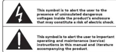
06Bn69eBnHmN BBAWPOCTOHNHE TpeyIbHInke PNDyPExkAaTne NbIb3oBaTeTn O nBNHbHn HINBKNKOPKCA KENDAIIN 86HNO10PBOAHHO HrnpKApHnB, BvNNHnHKA KOTOPOKoE MoTcCoABdAtnObACHoCTb PnOxHKnE VJIOBeka NQKTHDVKCMKTKOM.

Mo3OpaKoJHbO BocNtIaTeBnHO 3NaKa B aBpHoTOponHem TpeYrOtnHKe IpeDyPnEeKaTaeTOnBIOteBaTe O hAnuHN b CnpOBoXAODaouei Annapat DOkMyETMaHg BAKhIN XHcTpyKnO NxCckYtaUaQm iTexHueKowcy OMByKXBAHNO.

PpOyKtBrotelcnpoeKTHPOBaHbTaT,QTO6bI COOTBeTCTBOBaT Tpe6oBaHmM MeJHyapOHaBIX DnpeKTHN OOrpaHueHHeNIO pNMeHHeH N BpeDhBX BueCTCB 3NeKTPoTeXHcECKOM N3NeKTPoHHOM 06pyoobAHn (Restriction of Hazardous Substances -RoHS),Takke No 6paueHncoTcykNBHM Cboi CpOK 3NeKTPoTeXHcECKHM N3NeKTPoHHBM 06opyoabHem (Waste Electrical and Electronic Equipment-WEEE).N36paXeHnnepeepKhYtoro MycOpHO 6aKa Ha Konecax O3Haayet TaKke To, QTO 3TN PpOyKtBDOJKNbB 6bItB BToPnHo NcNoB3oBaHbI (peuKnnpoBaHb)nnn JKe 6pa6oTaHb B COOTBeTCTBmC CyomnHYtbIM Bblue DnpeKTHBaAM.

Copepkanhe
Pcymok1:OprahbIyypaBnHnpa3beMb3
PmcyohK 2: PnOcOeUHHeHne-npMmep 4
Baxhblc3ameyann 5
Baxkhhe Hnctpykuu no 6e3oNaChoctn 53
OKOMnHaHnROTEL. 54
HeckoBko CnoB O MoUHocTH B BaTax 54
Iepbile war 55
HekotopbIe MepbI npedoctoepoKHOCTn 55
Pazmeuenne 55
IopknioueHne nHTAHn H npabneHn 55
PaBem dIa CTeBOrO uHypa 55
BbkiuoyateIb nHTaHn HnDikatop nHTaHn 55
IpeeknHouateBpekima 55
12-B TprrreBn BxoM BbXoD 56
HINDAKATOp 3aunltb 56
IopcoeHHe BxOaHbIX CmHaNoB 234 56
BxOblrCA 56
Coppengene BxnoB 56
IpeeknoateBpekmMoHO 56
PeryuropBKn BxOdbx ypOBne 56
BbXoN npeducnntra - Preamp Out 57
OHTHueckHe BxOdbI 57
BbIXObl Ha akyctHueckne cHCTembl 57
Bb6op konohok 57
Bb6op akcyteckoro k6en 57
PnIepnoctb n 57
IpoedoeHHHeAkyctHecKHX CHTEM 57
Pazbem WmHb RS232 58
BentnIaTOpbl Ira OxnaKeHn. 58
Bo3MOKHbIe HcnpaBHOCTN 58
HnDkaTOp nTaHa Ha nepeJeH naHe H CBeHTcra 58
HeT3ByKa 58
HdkaTOp 3aunrmbrae 58
Texnueckne xapaKtepeCTNkn 59
OKompanHnROTEL
NCTOPHn Haew KOMnAHn Hauanacb 6Oonee 50 let Haazad.3a npweJHne DecTINETM MbI NOyUHm COTHN HarpaD 3a Haun npOyKTb NcEJaNN CACTINBBIMn COTHN TbcH NIOJe, KOtOpBle OTHOCTC KCBOM pa3BneEHnM BNOJIHe cepBe3HO -Tak Je, KaK Bbl!
KOMnHaR RoTe 6bIa OCHOBaHc CEmeNCTBOM, Y8c TcPaTb K My3bIke npoDmHa CTpeMHeHcO3daBaTb hi-fi KOMnoHeHbI 6eCKOMPomUCCHO KaueCTBa.3a MHOrne rObl tA STa CToPact HnHyTb He OcnAbla, nNo cEh DeH ob6uae cEbl - BByIyCKaTb IPOdYkTBnICKJIouHTeNBHOJ UEHOCTHn dInyauNOfVIOOB NHO6HTene My3bIKn, He3aBNCIMO OT INx fHNaHCOBbIX BO3MOXHOCTe, pa3dJeIeTcBCEMI cotpydnKamr Rotel.
INHXeHepb Rotel pa6oTaIcK kEiHnHa KOMaHdA, pOcLyuBnA nTtSeIbHo DOBOyKaKDb HOBm npOyKT Do Takoro yOpBnCobepHeCTBa, KOra OH 6yTeYIOBNETBOPATb IN CTPOIM My3bikAihm CTaHapTAM. IMnpEOCTabHe cBObOa Bb6opkOMMIKeTKyUxN NO BCEMy MUPy, YTO6bI CEnaTb annapat KaK MOxHO NyUe. BepoTHo, Bbl CMoxTe HaTN B HauXn annapaTx OToBPhe KOHeHCATOpbI n3 BeNIKOBpTuHaHn I TepMaHn, NOnynpoBoDnKn n3 JnoHn nCUSA, ODAKO ToPouJaNbHbIe CInOBbIe TpaHcΦopMaTOpbI mN3rToBnBaEM HA Co6CTBeHHOM 3aObe ROTEL.
BceMb3a6oTUMc06oxpaHeOkpykaIoewe CpeBn. IIO Mepe TOrO, KAK BCE 6oJIbIe 3NeKTPoHHbIX yCTpoIeTB MIMPe BblNyCAeTCa, a Nocne OKOHuaHIN cPOKa CnykbblbipacbIbaeTc, nIpnO3BODInTeI Oco6eHNO BaXHO npN KOHCTpyuPobAHIN pOyoKTOB CdeJaT BCE BO3MOxHoe, YTObI OHHaHOCIN MNHMmAbHbYyuep63emIe N ICTOHTNHAM BoIy.
MbB KOMNAHNN Rotel, ropDmCBA BOKN BklaDM Bo6e eNo.Bo-epBbIX, MBI COKpaTNII COePkaHHe CBNtA B CBOE 3a CHTNOJIb3OBAHn IpINoR, OTBeauKIOero Tpe6oBaHnAM ROHS. Hauu INHXeHEpbI NOCTHO CTpeMTCy yUunTB K.I.D. 6IoKOB NITAHN, 6e3 yUeepBa IJRA KaueCTBa 3ByaHn. HaxoJcB b PexIMe OxNDAAHn STandby npodykTI RoteL nCNOJb3yOT MNHMnALbHoe KOJIueCTBO 3Heprn, 4To6bl YDObNTBOpNTB IIO6aJIbHbIM Tpe6oBaHnAM Ha notpe6IeHne B pexIMe OXNDAAHn.
Фбрнka RotelТakkeBHCNT CBOB BknaDByuynueHne OxpaHbOkyKauUepeCpeblnyTmnoCToHHOR COBepseHCTBOBaHnI pOn3BOdCTBeHHbIX npouecCOB,ДелЯnx BCE Boonee YNC TbIMN «3eneHbIMN.
BceMb,coTpydHnKoKmNaHnROTEL,6laOaapM Bac 3a NokynkToTOI3denn. Mblybepehbl,TO OHO DOCTABNT BAM MHORoNET yDobOBcTBnR.
HeckoIbko cNoB o MoUHocTn B BaTTax
BbXOHaMaOuHocTbYcNnTeJI RKB-850 n RKB-D850 coCTaBnReT 50 Bt Ha KaKdbI n3 KaHaNOB, RKB-8100 n RKB-D8100 - 100 BT Ha KaKdbI n3 KaHaNOB, npi BceX OBCbMn KaHaNax OndOBpemEHNO pa6oTaOHx HA NoHHy MOuCb.
KomnaHnpeunna n3mepaBbIXoHy MOuHcT bmeHHo TaKIM MeTOOM notomy, yto no onby Rotel, toIbko OH daet nCTHHy OeHky Bo3MOxHcTe peCnBepa nn ycInntela.
CpaBnBaI daHbIe B TexHuecknx xapaKTepeNCTkax pa3nnHbIX npOdyKTOB, HxJHO IMeTb B BNy, YTO BixOHaH MaUHocTb YaCTo INMepaETcR coCBem dpymI cnoCo6OM, TaK YTO, BO3MOxHo, Bbl NItaeTecb CpABHHTb MekDy co60i COBepseHHO pa3HbIe Beu.
Hapmep, BixoHaMa MoOHOCTb MOKeT 6bIb PnBHeHa TOnbKO IaONHO pa6oTaIoero KaHana, yTo No3BOJNeT NOyHTb 60oe BbcOKn NOKa3TeB MaKcMaaJIbHO MoOHOCTN. BbcOKKaueCTBeHHble 6Iokn NITAHy YcINITeNe RotoRapaHTnpYIO, 4To OHN BbIAOTnoHHy 3aABneHHy MoOHOCTb KAK B OHDOM, TaK IN B DByx KaHAnax.
IMnpeaHc akyctuuecknx cntem noka3bBAeT, kakoBO 3neKtpnueecko coPOTNBHeHne nn Harpy3ka, noKnIOuaMaHa H BbXo yCUNTeJI, n 06bUHO OHa paBnaTc8 OM nnn 4 Oma. YEm HnKe IMpeJaHC, Tm 6Onbua MoOHTb Notpe6yETc IIN KONOHn. B pe3ynbTaTe, akyctuueckra CNTema C conPOTNBHeHnEM 4 OM Hykdaetc B ycunIte TE BDOE 6OnbWe MoUHCTN, Yem 8-OMHa AC.
Ondako ycninten RotoeKpOBaHb TaK, cyo pa6oTaB CIO6bIM
mneJahcom KOHOK -OT 8 OM Do 4 OM, npu BceX kaHaJax ONDOBpeMeHH
BbIaIOUx NOnHyIO MOHOCtB. I TaK KaK KOHCTpyKUn RotoI ONTUMN3UPOBAHBI
dIy NCnOJIb3OBAHnco BCEMN ONDOBpeMeHHo pa6oTaIOUIMK KaHaJAMR, Rotel
MOKeT Yka3bIBaTB NCTINHHy IOOHOCTB dIy OBOX KAHaJIOB.
3TO MOKET OKa3aTbCAHpe3BbUaHNO BaxHO IINBAuNX BneUATNeHIN. PnnpocmOTpe KINHOΦNlMbMO XeIaTeNbHO, YTO6bl YcUNITeNB MOR BbIdaTBIOHNyMOUHOCTB BO BCE KaHaJIbOJHOBpEmHo, OCO6EHNO KOrHa HA EKpaHepoONxCODNT N3BepKeHHe BykKaHa!
PepBbIe warn
Bnaorapn BAC 3a npno6peTHeN 8-kaHbHorO yCnnten MoHocn Cepnn RKB. Ppi nCnObl3oBaHHm B BbICOKKaueCTBeHHOn CnCTeMe IJRA BOCnpOn3BeDeHnMy3bIKnIIN DOMaHHeRo KNHOteAtpa, BaW yCnntenB ROTEL o6ecneHT roDby yDobONbCTBnOT pOcNyWBnHa.
YcHNTeR KRB-3ToMoUhBiyeCYNITeIN,06ecneuBaIOUme HauBicuIypOBeH KaueCTBa 3ByaHnA. MoUhN hntOuyHK nTAtnH,OTbOpHbKOMJIeKtUOHe npemym-Klaccn AmpMeHHa KOnceuC6aHaHCnpoBaHOrO INa3aHa (RotelBalanced Design) oecneuBAiOt ppeBOxCODHe KaueCTBo 3ByaHnA. Cnoc6bocb ToDaBaTb BoJbwo ToK No3BolJeT Emy JERKO cnpabTbcA CamaMIM TpydHmHnHarpy3kAMn B BuDE KOHOHOK.
UyTne, yTO yCNNTeIeI MoHocTc CepR RKB cnoo6bI pa3BnBaTb 60nbuy BbxOHNyIO MOHOCtB. Y6eINTeCb, yTO BaUN AC dONyCKaKOT NOBEdHne TAKOI MOHOCtN. B CNYue cOMHeHNI NocOBetyTECb aBTOpU3OBAHHbIM DInepom Rotel.
3Tu ycnntnnpocbI B hacptpoke n 3Kcnnyatauun. EcnBbyxge menn deo C dpymn ctepeo ycintelma MoHoctn, y Bac He Bo3nKnHET Bonpocob. PpOTo NOcoedHInTe dpyrne KOMnoHehTb K BXoam BaWero ycNtela MoHOctn, Hb BixOdbIO NKIOUHTe KOLOHNi HacnaJdaNTecb.
HekotopbIe MepblipedeoctopoxkOCTn
PIMMEYAHNE: ymo6b u36baxmb Bo3MoxHo2o nobpeXedHuae bue cucmemb, bkiouhme BCE komnoehmb cucmemb npu nodcoedunhuu UU omcoedunhuu akcmuueckux cucmem unu dpyzx cb3aHHbx kOmoHmOB. He bknouaumekomnoehmb cucmemb noka Hey6dumecb, mO BCE coedunhura BblonHeBn npabunbHO u HadeKHO. Ocboe BHumane ydenume Konoohybnnpobodam. He donxho 6bmb pa3noxmauenhhx KOHOb, Komopbie bblkacanucb dpyzx npobodob unu Kopnyca ycunlmena.
IpoKanyiNCTa, npOHTaTe DaHHe PyKOBOcTBo BHMaTeNbHO. KpOme OCHOBbIX NaCTaBnEHH NO YCTaHOBKe NkCnPyatauNN, OHO cOpEKNr HOpMaUIO o pa3nUHbIX KOHfynpyaunx CNTeM C yCNITeLAM MoUHocTN CepMN RKB, a TAKke obuune CBeDEHN, KOtOpbIE NOMOT Bam ONTUMNInPOBaTB KaueCTBO pa60bTa Baaen CNTeMb.IoKanyiNCTa, o6paauTeCB KBaAeMy ABTOIN3OBAHHomy DInepy Rotel 3a OTBetAmHa IIO6bIe BOIpocbl, KOtOpbIE MOYr BO3HKnHYb. KpOme TOrO, IIO6oBcoTpudHKn Rotel cyDobOJbCTBnEM nPmET BaUN BONPOcb IN KOMMeHTapnn.
CoxpaHnTe TpaHcnpTHyK KaptonHyo Kopo6ky OY cunnteR RKB INBCE BLOXeHHBe yNAKOBOUHbIe MaTePnAJIb IIN DaJIbHeIwero NcNOnb3OBAHNr. TpaHCnOpTnPoBaHne INI nepeMeueHne ycUNTeR BInIOBo Tape INyakOBKe, KpOME opuHaHbHO, MOKeI npNBecTN K cepBe3HOMy NOBpeJdHIO BaWero ycUNTeR.
EcB Kopo6ke ecb pernctpaunnoHna Kaptoka Bnaednba, 3anoHnnte ee n BblnteHAM.Coxpahnte Yek O npdaJe. OHraJrTaC Hnnyuwe pernctpaunei DaTbI pnp6peTeHHN, KOtopa 6ydt Bocptpe6oBaHa B Cnyae rapaHTnHorO 06cnykuaHn, ecn OHO KOrDa-Jin6o Nohao6ntca.
Pa3meueHne
YcunntenRKBbIeJIaOTTeIIO npHOpmaJIbHO pa6Ote.He 3aropaxBaIte paIaTOpBnBEHTINJauOnHbIe OTBepCTN.BENTINJauOnHbIe OTBepCTNa HA KpbIuKe HHa DInIe DOJnxHbIb 6bITb OTKpbITb.EcI NTO BO3MOxHO,OCTaBIAJIte He Mehee 10cm CBO6oDHoro nPoCTpaHCTBa c3aDi KopNyca. IpryCtAHOBKe B CTOKy INI uKaΦ,y6eNTeCB,TOTam CyueCTByET Heo6xOdMaB BEHTINJauZ, UTO6bIu36eKaTb NpePpeBa.
POMHNTe O Bece ycINHTe npn Bb6ope MeCTa Dn ero pa3MeueHn. EcnBb He NcNoIb3yeTe peKOBBe "yU" nJr MOHTaxa B CToKy, y6eDInTEcb, YTOONKaHNI uKaΦ MOrY T bIepeKATb erO Bec.Mb peKOMeHNyEMyCTaHABINBaTb 06OpuyoBOAHne B Me6en, cneuaNbHO cKOHCTpyuPoBAHHUo DnA ayDnO KOMIOHETOB.TaKaMbe6enCbnpoeKtPOBaHaTak, YTO6bI NOaBnTb Bn6paun,OTpuAtelbHO BnIAIOUe Ha KaueCTBO 3Byka. Ioxaanycta, o6paauTeCB KBaWemy ABTopi3OBAHOM dyinepy Rotel 3a cobetamn no Me6en dna aydno KOMNOHETOB IN PabINbHO INx YCTAHOBKe.
IopknloueHne nTaHn ynpabHeHHa
Pa3bEmIa cTeBoro Whypa
BaW yCnInTeNb npDyCTaHOBHeH Ha a6pRKe HcTaHdApT cTeBOrO HanPjaKeHH B CTpaH, rE OH npNo6peHEN (CUA: 120 B/60 Tg, EBpona: 230 B/50 Tq). 3TO tAndapt yka3AH H 60KoBOH naHenn.
PIMMEYAHNE: Ecnu Bn nepeedeme 8 dpyuycmpany, moKho npucnocumb yculumenb Kdpzomy cemebomy HanpJxehuo. OHaKo, He nbimaumecb cdammbmo camu. Omkpbie Kopnyc ycunumena, bM oKeme nonyumb yap mokom, onachbl dny Ku3Hu. O6paumecb K KeanuupuupobahHomy Macmepy unB cepbuhy Cny6y Rotel.
IPIMMEYAHNE: HekomopbIe npodykmbI npedHa3Hauenb I nny npodaku 6olee yem B odhoI cmpaH e u no3momy nocmaenlomc C heckonbkmu cemebbmu Ka6eMa. IVcnolbyme molko mom Ka6eB, Komopbi nodxodum dna baweo peuoha/cmpaHb.
Bvdu BbICOKo BxIOHOH MOOHOCTN yCUNNTB NoTpe6JIeT 3cTe 3NaHTeNBtTOK. NToMY ero MoKHO BKNIOuATb ToIbKO HENOCpeCTBeHNHO B HAcTeHHyIO PO3eTKy. YCUNNTEN RKB DoJXHb 6bITb O8a3aTEbHO BKNIOUeHb B-3-KoTHAKTHyIO NOJARIN3OBAHHyO pO3eTKy. He NOb3yIteCb yDInHInTeHMI. MoKHO nONb3OBaTB pa3BETBNTBn NITAHNA BICOKO MOUHOCTN, eCN OH (n HAcTeHHa P03eTKa) CNOOCbHb BiJeepKaTb TOK Notpe6JIeHn yCUNNTEN I DpyNX KOMNoHEHTOB, BKIOUeHHBX B pa3BETBNTB.
Y6eINTecb, YTO BbIKIOuATEb NITAHIN PAWER 1 Ha nepeHne NaHEny YcNlNTeHaXoNDTCB NOIOKeHNN OTKIOUeHO.3aTEM BOTKNITE OINH KOHeC CTeBOrO WHypa B pa3bEM 9 Ha 3aDHeN NaHEny YcNlNTeI. Pocne 3TOTO BCTABTE DpyroR KOHeC CTeBOrO Ka6enC BvIKoN B PO3ETky.
Ecnn Bbl haonro ye3kaete nD oma, hnapmep, hMa meca, pa3ymho 6ynet BbHyTb bNkn shypoB nHTAHn yCNNTeY nDpynx ayDNO-BnDEO KOMnoHETOB CNTEMbl n3 p03eTOK.
BbIKIOATENB NHTAHN INHIDKAtOP NHTAHN
BbKIOUOATEb NITAHIN paONIOKeH Ha nepeHne nane Hauero ycNInTeIe.
DnBbKIOUeHn yCUNTEIe, HaxMMte Ha BbKIOUaTeIe. KOBueBo INndkaTOp
BOKpyr BbKIOUaTeIe 3aRopITcN mMIRHT TpN pa3a, NOKa3bIBaR, YTO ycINlTeIe
BkIOUeH. YTO6bbl BbKIOUHTb ycINlTeIe, HaxMMte Ha KNOHky eue pa3 n BepHInTe
ee B NOIOJKeHHe «BbKIOUeHO»
INPMUEAHNE: Ecnu cbeuehue cuHezo KOnbueo2o uHdukamopa bokpye BbIKNoyameI naKaeMcra Bam CnUwKom rPKUM, MoXHO 3aIenumb eOc CAMOKTneuUMC KOJIboum.
IpeeknouateIb pekma
Ycnnnten RKB oecneuBaIO TpN pa3nHbIX BO3MOxHocTIN pyuHOro nIABTOMaTHeCKrO BkIOeHm/ BbIKIOeHm IITaHn. 3Tn pexMbblb6paOTc npn NOMOu TpExNo3uONHO rpeKIOuTeHa zAdHe naHei:
Korda daHHb nepeKIOuateHb HaxoITcB nNoXeHN OFF,ycnIHTeB BKNIOaOT N bIKIOUaOT BpyHyIO pIN NOMOUI KNONKHa nepeDHe naHEi. TaKe IcNtOB3yTe 3OT peKM,ecnBaHa po3eTKa nepeMeHHoro TOKa cHa6KeHa BkIOUaTeLEM dY npabNeHn IOnaey nTaNHa ycNITeB;
Korda nepekIouaTeB haoDITCB bIIOJoxEHNI SIGNAL SENSE,ycnInteB BkIOUaTcABToMaTHueckn pIn oBHpXeHHy ayDINO CIRHala Ha BXoAa. YcNlnteB nepeiTeB JxdyuIN pejIMn I nepeHna HndkaTOp NTaHn 6ydt Tycblm npImepHO ue3 10 MmHT nOcNE TORO, KaC cHnHa N 6ydt ObHApXeH. KhONKa hnepeHn paHEN 6loKpyET 3Ty fHyHKNUO. OHa dOJIxHa 6bTB B NOLOXeHHN ON, yTO6bI cxema oBHpXeHHa CIRHala pa6oTana.IpeKIOUeHHe KNOpKn B NOLOXeHHe OFF oTKIOUaET NTaHHe OT yCNlnteTHe, He3aBNCIMMO OT TORO, pNpCYTCTByET CIRHaN INI Het;
Korda nepeknioateIb haxoDITcB noLoKeHn+12VTRIGON,ycnntelb BknoaetcABTOMATUeCKN npn noBHeHn 12-BonbTOBOrO cHnHaHa BxOe TRIGGER IN Ha 3aDHe nAneHn.Ycnntelb nepeoxoNT B KdyuippeKIMn nepeDnHa HndkaTop nTaHn6yTe TycNbIM,ecn 12-BonbTOBbCunHnHet.KhONKaPOWERSWITCH Ha nepeDneHn naHn E6loKnpyET tyfHKuIO.OHa doJnxHaHXoDITbcR bnoLoKeHN ON, YtO6b1 12-BonbTOBb 3aNyckaoUcunrHn paOtaI. NepeKluOeHne KhoNkB NoLoXeHne OFF otKnIOaET nTaNHe oYcnnte, He3aBncMoOT TOR, npncytCTbyET 3aNyckaoUcunrHn nIN HeT.
12-B TpnrrehpBn BxO n BbIXoD
Tne3do c Mapknipobkoi IN npedna3haeNo InpncoeHHeNn Ka6en 3,5-MM wTekepom, Hecyuero +12-BolbToBbI 3ayncKaHO uCnHAn OT npdycnInTeJe NII npoceccopa, BKNIOauHOUs N BbIKIOUHO uCnInTeJb. TObbepeaIm3oBaT 3Ty cyHKUHO, nepeKnIDHO nepeKIOUATEb doJxhen 6bItb UCTAHOBEN B noLoKeHHe ON. 3TO T BXOJ pinnHMAet IIO60ynpabHIOuN CnHAN (pepeMeHHoro NII NOCTOARHORo TOka) B DuaNa3Ote O T 3 Do 30 BoJbT.
THe3IO cMapKpOboKoOUT npEHa3HaueHO dI npncoeDnHEnH eue Ondro Ka6eNc3,5-MM WTekePOM, oBecneuBaIoJero 12-BolbTObB nyckOBo CnHan DnApyrNX KOMPOHeTOB. BixOHOH 12-BolbTObB CnHAn NOABJeTCaBCaIK pa3, Korda 3anyckaoiun CnHAN +12 B npInOnKe H THe3dy IN.
ITPUMEYAHNE:MaKcumalbHbIMOKHa mpu2epHom BbxOe ccmabnem 10MA.
HdNkTop3aunTbI
Ycnnntn RKB ochaenb cyemamn 3auntb, B TOM uCnne TepnoBn n OT npebblene HTOka, KOTOpbI nepeDToBpaauHOT NoTeHuaNbHoe NOBpexKeHne Ycnnntn B Cnyae EKCTpeMaNbHbix CNTyaun nn COCTOHN OTKa3a.
Ckopee Bcero, BbHnKOrda He yBnuInTe, KaK pa6oTaet cxema 3aunTbI. Ondako, npn Bo3NnKHOBeHHn OTKa3a YCuINTeNb NpeKpaAaET BocPOn3BedeHne n HnDnKaTopHbN CBToOnIOD POWER Ha nepeHne NaHEn NaHnHaET MIRAtb.
Ecn3o cnyntcra, BbKIOUHTe ycuNTeb, daIte emy octbIte HeckOblKO MHNyt I nonbTaTcB 6hApuykNTb HNCpabNTb npo6nemy. Korda Bbl BKIOuaeTe ycNtEnb ChOba, Cxema 3aunTb ATOmatueckn C6paCbIAeTc NINHdkaTop POWER 3aropaeTcNoCToHHbIM CBETOM, NOKa3bBAB, TcYcNlNTeB BKIOUHnCR HopMaJIbHO.
B 60bnHCTBe cnyaeB, cxema 3aunTbA kTNBpyeTcBpe3ynbTaTe HecnpabHocnT, Tako KaK KOPOTKe 3ambKaHne B akyctnweckOM Ka6ene nn HeoCTaTOHARBEHTINLAuN. B Oueh peknx CnyaX, Cp6aTbHaHne cxembl 3aunTb MoKeT oOyCIOBt BbICOKaPeAKTNBOCTb INI Ype3bbHauHO Hn3KnIMmpeDAnC rPOMKOrOBOpNTeHarpy3kn.
Ecnn cxema 3aunTb cpa6aTbIaBaeN NOBTOHO Bbl He MoKeTe BbIaBHTb NyctpaHtB HeNCnpaBHOCTb, CBAKNTecb CO CBOMM DnIepom ROTEL nIPOMOU B NOUCKE HeNCnpaBHOCTn.
ПодсоeДиНeHnE BXOДнБIX CnRHaIIOB 234
Cm.pucyhoK 2
PIMMEYAHNE:ДяnpedombaueHnnaomeuauhno onauchbx2pOMkux 38ykoB y6eumecb,уmo cuemema bkyloueHa npu noKnoueHu BXOdbix cu2haNo.
YcHNTeIN RKBOCHaueHbI CTaHdapTHbIMN,He6anaHChbIMN BXoDhbIMPa3beMaMn Tnna RCA,Kakne MoKHO HauTN NOuTN BO BcEM ayDINO o6OpydoBaHN.
BdononHeHneKcTbIepm rpynnam Ctepeo BxOOBcMapKnupOBko ot INPUT Ado INPUTD,Imeetca TaKke npapa pazemob PREAMP OUTPUTdna nepedaun BxODnHO CnHaJa,NoDKloueHNHO Knape KaHAnOB INPUTA,HaDpyroe ayDno 60bopyoBaHne.
BxOaB RCA
Дя каддиИЗ сьчспap kaHалов ycHnnteIусшсьТВд bXODa RCA.3TN RCA BXOы пинмалOT ayDINO cHnHbI OT npdBapITeNbHbIX yCnNTeIeI nII npoecccopOB OkpykaIoJero 3Byka.ДЯ obecneHENHaHnyuHnx napamTePoB, IcnoJIb3yIte MeK6bNoHbIe Ka6eIN BbICOKOrO KaueCTBa.
Дя каду napы каланов усунтеля, писецнчte Вьхд leboro kahana bawero npedbarupentelbHoro ycunitelera KBxody LEFT INPUT ycunitela. Bbxod npaboro kaana npedbarupentelbHoro ycunitelera pисецнчte KBxody RIGHT INPUT.Y6eintecb,yto nepeknluovatelb INPUT SELECT haxodntcB noIoxhen STEREO.
CopjxKHe BxOdoB
BbMOKeTe CBA3aTb aHAnorOBBe IuNΦpOBe BxOBoIpyrnxKaHaNob,nepeMeuaa nepeKIOUaTeNbLINK/STEREO,pacnoJooXeHHb pAOMcBXoAMn RCA dna KaHana B,CnD b noJoxeHneLINK.Korda 3OT nepeKIOUaTeNb yCTaHOBnB nnoJoxeHneLINK,aHAnorOBb uNΦpOBoN icTOUHk npdeBdyuero KaHana 6yETNCNoB3OaTbCnIg TOrO kaHana.1Na KaHana CBKNIOueHHbIM LINK,He Tpe6yTeCnTOUHnKaBXoDHoro CnIHana.HanPImep,ecn KaHaN CyCTaHOBnB nnoJoxeHneLINK,to 6yETncNoB3OaTbCnΦpOBo Nn aHAnorOBb icTOUHKn KaHana B.
INPMEYAHNE:Kak ananooobbe,mau uucfpobbe xoohbte ucmouhukc 6xoda INPUT A mozym sbmb nepehanha na xoob Input B,Cu D.
IpeeknloaTeB BpekIM MoHO
ДяканалINPUTA,Когда nepeknioquateNBxOOB HaxoDITCBnnoJKeHIM MONO,BxodIeBOrO kaHana coeHHeC npabMb KaHAnOM nNoaETcHa 06e konohKn kak MOHOcHaN. KaHaNbI,coeHHeHHbIe CBxoDM INPUT A, TAKke nepeynDyT B pexMM MONO,eCNn nepeknioquateNB6ydet yCTahOBJIeB nnoJKeHne MONO.
PerynpoBKn BxOaNbIX yopBne
IodctpoKy BxOJHOrO yOBnHO oBecneuBAoT cTeblpe opraHa ynpabHeHnHa H nepeDneH naHEn -no ONDHomy IaI KaKdoI napbKaHAnOB. OHnO3BOJnOt Bam OTperynipobatb Ko3ΦnUeHT nepeDaun ycNITeJI, 4TO6bIOh COOTBcTcBOBaI dpymKOMnHOENTam daHHOn CInCTembl. PerylanTop yOBnKaHAnOB INPUT A n3MeHReT Ko3ΦnUeHT nepeDaun KaHAnOB INPUT A; INPUT B n3MeHReT
Ko3ΦnueH TpeaHa KaHAnOB INPUT B, n Tak Daee. OpraHb ynpabHeHnKaK He MapKnpoBaHb Ha nepeHne NaHEn, Ondako BXoDb paacnoJoxeHb CBeBA HnPaB: Input D,C,B,A, npn 3Tom BxOa A - cnpaba.ДЯ noDcTpoKn mCOnb3yIte He6oBshuO OTBepTk Cnlockm ShnIcM. NobepHnTe perynlTop no Yacoboi CTpeKe dnyyBeneHn K03ΦnueHtA nepeaHn. NobepHnTe perynlTop npotmb cacoboi CTpeKn dnyymbeHsE HN K03ΦnueHtA nepeaHn.
BbIXo npeDcunnte - Preamp Out
3ta npapa pa3bemOB RCA moKet 6bTb nCnObl3oBaHa dI na nepeaHn Heo6pa60tAHhBix BXOhBix CnHAnOB Ha DpyroAayIO KOMNoHEn, HApNIMep, dI na KacKaInpOBAHHa IOnONHInTeBHO yCNInTeJIa, pa6OtaUeHO HA BTOPOI KOMnEeRr pOMKOrOBOpTeJIe. 3TN BxOHNbIE CNHbJI, npCooEINHeHbIe K KaHANAM INPUT A,doCTynHb TaXke dI na nepeaHn Ha BxOJbPreamp Out. O6buHNO OHn cNOnb3yIoTcKorDa ycNInTeJBRAIeTc qAcTbIO MyNbTnpymHO cnCTeMbl.
PIMMEYAHNE: PeKOMeHoyemcra coedunm b enoou He 60nee 8 ycunumeneu muna RKB.
PYPMEUHNE:pepekIouamelbMONOHeBnueHaBaXoDbPreampOut.
OnTnueckne BxOdbI
Tolko dRkB-D850u RKB-D8100
ДлякдогиИЗКананов IMeIOTcONTUHecKHe BxOdbI,МарКИрOBAHbIe OPTICAL. CoeINHnTe BbyOdbI OPTICAL PCM BaWero KOMnoHEHa T NCTOChNka C 3TmIM pa3bEmAMN. LInPpOBBe CnHaNJIb 6yDIT DeKoINpOBaHBi N BocPOn3BedeHbMoDEJMM yCunNTeJIe RKB-D850 nIN RKB-D8100.YCunNTeJIu RKB cNoco6hbldeKoINpOBaTB PCM cnHaNJIb c p3peWeHem Do 24 6nt,192 kTg.
PIMMEYAHNE: Bxod OPTICAL 6ydem abmamuuecku b6paH, kak monbko Ha bxode o6hApkyen ufpbooCu zuaH. Hekomopbue ucmouHKU npodonkaom nocblanmb ufpboo cuHaan, dake Ko2da ayduo cuHAN yke he nepedaemc. Ipumepamu Mozym cnykumb Hekomopbie CDnneepb, Komopbie npodonkaom nocblanmb ufpboo cuHaan, daoke cnu CD duck ocmanohEn unu bpeKume nay3b. B makux cnyaax 803Mxho nompe6yemc bkiNouumb ufpboo ucmouHK UNU BOO6ue omcoedunmb onmuuecku Ka6enb, umobbi eephymbcra obpamno K anano2oBOMy RCA bxody.
BbIXoDbHa akyctnueckne cnCTembl
Cm.pucyHOK2
YcunntenMoHocTNRKBIIMEOTYeBPe npbI KIeMMIg rPOMKOROBOpTene, no OdnHOJ4KaKdo npbI KaHANOB ycunnte.BoceMb kaHANOB MOxHO nCnObl3oBaTbBpa3NUnhBix KOHfynpyaunx.Cxema NDoCoeHNHeHnHa PnC. 2 Noka3bIAeToBkoOdINnpmep, C NOKJIuyeHEm TINNUHO CNCTembl 3 WeCTN KONOHO.K B TakOM cnUyae ocTabwAraC npa KaHANOB MoKet 6bitb NCnObl3oBaHa DJI eEe DByX DonOnHInTeBhBIX rPOMKOROBOpTene,ecn 3TO HxKHO.
BbI6Op KOIOHOK
MbI peKOMeHdyem mCnOJb3oBaTb C RKB KOMIIeKT AC c mImpeHaCom 4 Oma nnn Bblwe. TOnbKO Onda npapa KOLOHOK DOnjKH aNoCDoeHNHTbC K KaKdo nape BbIXOHBx pa3bEmOB. Ecn pIncoeDHHb B npapAaJIb 60JIbe, Yem odHy npay KOLOHOK, MOXHO NOBPeINb TaWyCUNITeB RKB. YUHTte, YTO NaCnpTHbe 3HaueHnIMNeJaHca AC He CNiUKOM ToHb. Tem He MeHee, Ha pApKTne JInsb HEMHOrNE KOLOHKn MOrYT PnECTaBnTb KaKyTo-TO npObJIemy dnyUCmNTeJe
cepRKB.Ecyn y Bac ecTb BOpocbl,6paauaTecb K ABTopuOBAHHOMy dIepey Rotel.
BbI6op aKycTnueckoro Ka6eJIa
NcnoB3yIte n30nIpOBaHHb IByxIpOBoHO mHOrOxKnIb HbI Ka6eB bI npncOeunHeH yCInnte RKB K akyCTuWeckm CnCTeMaP. Pa3Mep n KaeeCTBO pOBoDA IMeOT 3aMeTHoe Ha Cny BnHHe He Na paMeTpbl CnCTeMb. CtaHdpTbI akyCTuWeckm Ka6eB 6ydt Pabotb, HO MoKet npNBecTN K ChnKeHIO rPOMKcTn INN OcnaBleHIO HN3KnX qAChT, OC6eHHO Ha 6bnXn pacCToHnX. B O6eM cNyae, 6Oe TOnCTbI Ka6eB yNyUwaeT 3ByuHne. DnHaNNyUnx NapaMeTPOB, Bbl MoKTe npMEnITb CneuaJIbHbIe akyCTuWeckne Ka6eB Nbl BCOKO KaueCTBa. Baaw ABTopn3OBaHHb IINep ROTEL MoKet NomOyB Bam B BblOpe COOTBETCTByuOxH Ka6eB dNra Baew CnCTeMb.
PonpaoctbuΦa3npobka
PnojHocbI nn noNoKtEnbHa/OpTuCaTeNbHa opnentauu coeHHeHH dnn KaJdOro rpoMKorOBopnteNdoJXhbl 6bItb corNaObaHbI, YTObI Bce akyctnueckne cnctembl 6bln B f3e. Ecn nolpnoctb odHoro coeHHeHH no Own6ke cdenaHa o6paTHOn, 3BvAHne Hn3kNx qactOT 6yET ouHbCna6bIM, a ctepeokapTnHa derpaNDpyET. Bce akCTnueckne ka6en npomapKnpoBaHb, yTO6bl Bbl MorIn OTmUHT bDa npOBDoHnka. 3To moKeT 6bl Tnooca nn pnoJHHeHa n3Olaunn ODHO npOBDoHnka. Ka6el MoKeT mEHT npO3paHyIO nOlaunc C npOBDoHNkAMn pa3HOrO zbeta (MeHbn I cepe6pHb). 3To MOryt 6bl N MeKN noJaPnoCTn, HaneuTaHhbie Ha n3Olaunn. OnpeJeNTe PNOxKtEnbHbN I OPtuCaTeNbHbN IpOBDoHNk IN corNaCyIe C kaxkbim pa3BeMOM rpoMKorOBopnteNryucnnteJI.
IpoCoeHHeHne akyCTnuecknx CnCTem
PIMMEYAHHE: Daee onucbjaemc nooceuheue K BuHmOBbM Klemmam u BCmabHb m pa3bemam. HE NCIOJIb3yIte 6a Memoda oHOBpeMeHHO CenbIO nooknloeHn Heckonbkux akycmuueckux cucmem.
OTKIOUHTBE CCKMOHENTbI, npexJe cemnoednHrB KOONHK. YcINHTeB MoUHCTR KRB IMeET no nape BnHTOBbIX KJIeMMC UBeTobO MApKUPOBKa H KaKdbi KaHaJ. 3Tu pa3BeMbI npNHMAIoT 3aUnIeHHbI pOBoD, HAKOHeuHNK TIna JNoTaKa IINI 6BaHaH (3a NCKIOUeHEm Ebponeckx CTpaH, rE IN npImeHHe 3anpeSeHo).
PpOLOKHTe npOBoDA OT ycINNTeRA RKB K KOJONHkAM. OCTaBte TnAce68doCTaTOUHy 3anaC, YTo6bl IMeTB BO3MOXHOCTb NpeMeueHnKOMNOHETOBC cIeJIbIO DOCTyNA K pa3BaEMAM rPOMKOROBOpTenei.
EcnBbI npmehreTe DBOHbIe WTEKepei -6aHaHbI, npncoeHNHe INK npOBoAMn 3aTEM BCTaBBTe Bpa3BeMbI DnI rPOMKOROBOpNTeN. 3aXHMhIE Btynk pa3bEmOB rPOMKOROBOPNTeN dOJXHb 6bITb 3aBNHcHbHa BCIO dnHy (no acoboi cTpeKe).
Ecnncnolb3yOcHnKHeJOnaTka》,3aKpeNITeHXHaKOHqax npoBDnKOB.EcnBbIpncOeHNHReTe3aunuHHeBKeHEnOpceDCTBeHHo Kpa3bemamrpoMkoROROpNTeJI,OTdEInTe npoBDnIKnCHmIMTe H0JauCIO C KOU KaJDO rnpoDA.5yDbTE BHNMaTeNBbl,YTO6bl He NOBpeINb TOkOPOBDAIueXnBb.OTBnHTte (npoTB uacBOOCTpeKl) 3aKImHyIO BTVynk pa3bema rpoMkoROROpNTeL.PacnoNoKtHe HakoHeNK BOKpyr OCN BTVKN, INIpocSyHbTe orOleHHb IPOBoD B OTBepCTne B OCN.3aBepHTne BTVKnI POACOBONCTpeKl,YTO6bl HAdexKHO 3aFHKCuPObaTB HakoHeNK INI npoBD.
IINPIMEYAHHE: Y6edumecb, ymo omdehbHbe «pa3noXmaeHbHe» KUNb1 npooba He kacaiocmc cocehux npoobodu un pa3beMoB.
Pa3beM uHHb RS232 5
YcHInTeMaR RKB MoXHO ynpabIbT no NocneBoaTeBHOJ WnHE RS232 IINTERpaun IN B CnCTemy ABOTMaTHaUN. Pa3bEM RS232 npHHMaet CTAnapThb Ka6enb C BuIKoDB-9 (Male-to-Female).
BeHTnIaTOpblIgOxnaXdHnA
B ycnntenax cepn RKB yctaHabnbaotc no 2 bENTnlaTopa nna OTboda Harpetoro BO3dyxa ot 6noka nntaanu n ycintentbhbix moynne. 3TN BEHTnIATopby kpyTATc c HopmaJIbHOH ckopoCTbO - NORMAL, KOrda RKB BkIOUeH n He haoNTcB pexime STANDBY. BeHTnlaTOpbl aTOMaTueckn nepeKIOauTcHa nobblIeHHyIOCKopoCTb-HIGH SPEED, KOrda 3TOrTO Tpe6yert DaTHIK BCtpoEHHOr TepMOCTata.
PIMMEYAHHE: B 3abucumocmu om Mecma ycmahobku moxem nompe6oamcbn nepuodueckay oucmcka bemunmopoe dna npabunbnozo oxnaxdeHua. Ceykumebc c baum dupepm Rotei dna nonyeHua boee nodpboHou uHfopMauu.
Bo3MOxHbIe HeNCpPaBHOCTN
BoIbIbnHCTBO np6nEM b ayDIO CnCTe max NOBIAOTc B pe3yIbTaTe nnoxN nn HeBepnbix coeHNHeHNI, Hn HnpaBnIbHbIX ynpaBnIouX nactpoek. Ecn Bbl cToIKNHyNCb C np6nEmaMn, I3OInpyTe 0bNaCTbNX BO3NHKHOBeHNA, npOBepbTe HAcTPOKn, OnpedeJIte pnuHny HeICnPABHOCTn i CdenaHTe Heo6xoJIMble NImeHEnHNA. Ecn Bbl He MoKeTe Do6ntcb 3Byka O CBOero ycInnteR RKB-1508, 6paTInTeCk COBETAM nIe CneDyoUnx cnTuayin:
HdkaTop nTuTnHa npeDne NaHeNe He CBtntc
Ha ycunnteB RKB He noaetc nitaHne. PpOBepbTe ceteBle pa3beMbl Ha ycunnteN B po3etke. PpOBepbTe BkiKIOuataBnNTAHNA H nepeDne naHEn. Y6eIntecb, yTO OH haxoJITcB nOIOxEHNN ON. Ecn nCNOlb3yETc BkIOUeHne 12-B 3anyckaoiUM CnHANOM, y6eIntecb, qTO 3anyckaiooi CNrHnnpncytcbYET B rHe3de 12V TRIG IN Ha 3adHne naHenn.
Het 3Byka
EcnHa yCnntBnNoaetcCteBoe HapnKeHne, Ho3ByK He BocnpOn3BODNTCA, npOBepbTe nHdkatop 3aunTb PROTECTION Ha nepeDneH naHenn. Ecn OH Miraet, nepexoDnte K cIeIyUoEmy pa3demy. Ecn HET, npOBepbTe BCE BaWN BXoDHbte pa3BeMbIn HacTpOuKN ynpAbeHHn DnN NOIDcoEduHEHHoro o60pyoDaBHn.
Hndkatop 3aunTbMnaet
INnikatop 3aunntb PROTECTION INDICATOR Ha nepehdne nane anna ratapaeTc, KOrda cxembl 3aunntb OTKIOUHN yCunNTeB.ObbuHNO,3TO npOxCoDHT, KOrda ycunNTeB neperpencra 13-3a 6loKnpoBaHnBEHTNIAuONHbIX OTBepCTNI, KOrda HnnpabUNbHO NOcoEHN He rPOMKOROBOpNTeB NIN Noocne nepNoDa paBoToHa MaKcMAbHNo MOHOCTH.NBkiKIOUHTe CNTeMy NIOOXJNTe, YTObbl ycunNTeB OCTbI.3aTeM HaxmITE NOTOXMMTE KNOKy BKNIOUHeH NITaHn HA nepeHne NaHEn, TTObbl6pcNTb CXEmbl 3auNTb.EcnIpObIema HeyctpaHena HInn pnoBnEeTc CHOBa, 3NaHT,OTKa3ana Ba7a CNTeMa INn camycunNTeB.
TexHnueckne xapaKTepeNtukn
RKB-850
BbXoHnMoHocHeNp.50BT/HaKaHAn(8KaHAnOBAKTNBHm) (204-20K4u, <0,1%THD, 8OM)
06ue rappmoHnueckne nckaxenHnTHD <0,08% (20Tu-22KTu,8OM)
HHTREPMOyIaUNHOHHbIe HCKXHeHH 0,08% (60T4:7K4,4:1)
DemnH-akTop >150
BxOHOH NmpeHaC/ yBCTBnTeBnOCTb 100KOM/0,6B
YcaneHHe 30
HnB30H qactot 20r-20k+0d/-1.4b
OTHOHHe cHTnAn/uym(A-83eeu.IHJ)108
Pa3deneHne KaHaoB>60 △B
HMMENANKONOHOK 4OM,MHHYMMy
Hannpexnne nntaahnn
CUJA:120B,60Fg
Ebpona:230B,50T
Tnpe6nemar moocctb 150BT
XonocToxOa:40BT
Standby: <0.5 Br
Tennobdyenehe BTU (4ohms, 1/8 MouHocmu) 180 BTU/uc
430×97×424MM
BbCota nepeHne nane 2U (88.1 MM)
Bec (hemmo) 9,3 Kf
RKB-D850
BbXoHnMoOIOHcHnP.50BT/HaKaHAn(8KaHANOBaKTHBbI) (20f-20KfU,<0,1%THD,8OM)
06ue rappmonnueckne nckakene THD <0.08% (20Tu-22KTu,8OM)
MnepmoynnoHHneckxHn 0,08% (60f4:7Kf4:41)
DemnH-0aktop>150
BxodHnMMpehC/yybCTBntelbHOCTb 50KOM/0,6B
YcneHn30
HnB30HactOT 20Tu-20Ku+0D/-1.4
OTHOWHHe CHTHAN/uym(A-83eeu.IHF)108p6
Pa3deneHne KaHAnOB>60
HMMNEHNCKOHOHK 4OM,MNHIMYM
LippoBae ceky
OTHOUHEHcIHAN/UYM(A-83eeu.HF)95d5
BxOHa yBCTBnTeBnOCTb -10d5FS
Ommueckne uippoobble cinnably SPDIF LPCM (do 192KU 246nt)
HannpaeHne nmtahm
CLIA:120B,60Tg
Ebpona:230B,50Tg
Tnpe6nemam Moocb 150Bt
XoocToxO45Bt
Standby: < 0.5B
Tennobbenehe BTU (4ohms, 1/8 mouhocmu) 180 BTU/aca
430×97×424MM
Bicota nepedhen 2U (88.1 MM)
Bec(Hemmo) 9.3 K
BceXapaKTePnCTmIK RnIaHOTcTOUHbIMHaMOMeHT Ny6JIkaUIM.
ROTEL octabnerta coo npabo BHOCHTb yuuchnna 6e3 ybcodmncna
RKB-8100
Baoqgma MoHcHb Hnp. 100BT/Ha KaHAN (8KaHAnOB aKTHMBH) (20F4-20K4u, <0,1% THD, 8OM)
06wne rapmoHueckne nckaeHH THD <0,08%
(20fU-22KfU,8OM)
VHTepMOyDyRUMOHHe WCKAKeHn<0,08%
(60Γu:7KΓu,4:1)
DemnHr-akTop >150
BxOHOHmmTeAHC/ycbCTaNTenbHOCTb 100KOM/0,9B
yuehe 30
Dnanaohyactor 20r-20Kf+0d/-1.4
OTHOWHEH CTRHAN/UM (A-83eeu.IHF) 108 n6
PaedeneHne KaHanob>60
Hmpehckonohok 4OM, MNHMYM
HanpxkHeHnTahns
CUSA:120B,60Tg
Ebpona:230B,50Tg
Tnpe6nma moohocb 300Bt
Xonocro xo75Bt
Standby: <0.5 Bt
TeepnboeheBTU (4ohms, 1/8 moHocmu) 279 BTU/uc
430×97×424MM
BbCota nepenennn 2U (88.1 MM)
Bec (Hemmo) 9.6 K
RKB-D8100
BbXpaMouHcHHeNp.100BT/HaKaHAn(8KaHaNoBakTnBHe) (20fU-20KfU,<0,1%THD,8OM)
06ue rapmoHneckn mckaeHH THD <0.08%
(20f4-22Kf4,8OM)
HHTepmorynunohhbe mckaeHH 0.08%
(60Γu:7KΓu4:1)
DemnHr-aktop>150
BxohHnnnnae/yyctwnenbno 50KOM/0,9B
yuege 30
Dnanaohyactot 20r-20Kr+0d/-1.4
OnhouheHmCmHan/uym(A-83Beeu.IHF)108a5
PazdeneHHne KaHAnOB>60
MmnehaKoNHO4OM,MMHMyM
LHPOBaa cekun
OTHOWEHNE CTHAN/UYM (A-63aeu.IH) 95 d6
Bxjha ycbntbHoc7 -7d5FS
2-11-4, Nakane, Meguro-ku,
Tokyo, 152-0031
Japan
Rotel of America
54 Concord Street
North Reading, MA 01864-2699
USA
Phone: +1 978-664-3820
Fax:+1978-664-4109
Rotel Europe
Dale Road
Worthing, West Sussex BN11 2BH
England
Phone: +44 (0)1903 221 710
Fax:+4401903221525
Rotel Deutschland
- Important Safety Instructions
- Notice
- Important Notes
- When making connections be sure to:
- It is also recommended that you:
- Remarques importantes
- About Rotel
- A Word About Watts
- Getting Started
- A Few Precautions
- Placement
- AC Power and Control
- AC Power Input
- POWER Switch and Power Indicator
- Trigger Mode Selector
- 12V Trigger Input and Output
- Protection Indicator
- Signal Connections 234
- RCA Inputs
- Linking the Inputs
- Mono Switch
- Input Level Controls
- Preamp Output
- Optical Inputs 4
- Speaker Outputs
- Speaker Selection
- Speaker Wire Selection
- Polarity and Phasing
- Speaker Connections
- RS232 Connector
- Cooling Fans
- Troubleshooting
- Power Indicator Is Not Illuminated
- No Sound
- Power Indicator Is Blinking
- Specifications
- RKB-850
- RKB-D850
- RKB-8100
- RKB-D8100
- Signalanschlüsse 2 3 4
- GELDT VOOR VS, CANADA OF WAAR
- Copepkanhe
- OKompanHnROTEL
- HeckoIbko cNoB o MoUHocTn B BaTTax
- PepBbIe warn
- HekotopbIe MepblipedeoctopoxkOCTn
- Pa3meueHne
- IopknloueHne nTaHn ynpabHeHHa
- Pa3bEmIa cTeBoro Whypa
- BbIKIOATENB NHTAHN INHIDKAtOP NHTAHN
- IpeeknouateIb pekma
- 12-B TpnrrehpBn BxO n BbIXoD
- HdNkTop3aunTbI
- ПодсоeДиНeHnE BXOДнБIX CnRHaIIOB 234
- BxOaB RCA
- CopjxKHe BxOdoB
- IpeeknloaTeB BpekIM MoHO
- PerynpoBKn BxOaNbIX yopBne
- BbIXo npeDcunnte - Preamp Out
- OnTnueckne BxOdbI
- BbIXoDbHa akyctnueckne cnCTembl
- BbI6Op KOIOHOK
- BbI6op aKycTnueckoro Ka6eJIa
- PonpaoctbuΦa3npobka
- IpoCoeHHeHne akyCTnuecknx CnCTem
- Pa3beM uHHb RS232 5
- BeHTnIaTOpblIgOxnaXdHnA
- Bo3MOxHbIe HeNCpPaBHOCTN
- HdkaTop nTuTnHa npeDne NaHeNe He CBtntc
- Het 3Byka
- Hndkatop 3aunTbMnaet
- TexHnueckne xapaKTepeNtukn
- LippoBae ceky
- HannpaeHne nmtahm
- LHPOBaa cekun
Brand : ROTEL
Model : RKB850 V2
Category : Receiver