SLX 32 LEDi High Cover 3h - Lighting Esylux - Free user manual and instructions
Find the device manual for free SLX 32 LEDi High Cover 3h Esylux in PDF.

| Product type | Self-contained emergency luminaire for emergency exit lighting and signaling |
| Brand | Esylux |
| Model | SLX 32 LEDi High Cover 3h |
| Dimensions (W x H x D) | 388 x 231 x 148 mm |
| Power supply | 230 V AC, 50 Hz |
| Power consumption | Approx. 4.14 W (permanent mode with battery charging) |
| Autonomy | 3 hours |
| Light source | Integrated LED (non-replaceable) |
| Battery | NiCd, 3.6 V / 1800 mAh (replaceable) |
| Operating mode | Emergency mode (jumper) or permanent mode (factory pre-set) |
| Protection rating | IP 54 |
| Electrical class | II |
| Housing material | Polycarbonate |
| Color | White (RAL 9016) |
| Operating temperature | +5 °C to +35 °C |
| Mounting type | Wall or ceiling, surface-mounted or with accessories (recessed, suspended, side-mounted) |
| Automatic test | Yes (function test 30 s, long test 3 h, weekly and semiannual cycles) |
| Maintenance and cleaning | Clean with a soft dry cloth. Do not use abrasive products. |
| Safety | Installation by qualified personnel. Disconnect power before servicing. Comply with applicable standards. |
| Manufacturer's warranty | 3 years (excluding battery, light source and batteries) |
Frequently Asked Questions - SLX 32 LEDi High Cover 3h Esylux
User questions about SLX 32 LEDi High Cover 3h Esylux
0 question about this device. Answer the ones you know or ask your own.
Ask a new question about this device
Download the instructions for your Lighting in PDF format for free! Find your manual SLX 32 LEDi High Cover 3h - Esylux and take your electronic device back in hand. On this page are published all the documents necessary for the use of your device. SLX 32 LEDi High Cover 3h by Esylux.
USER MANUAL SLX 32 LEDi High Cover 3h Esylux
MAC0464501 • KAT 09/14
• SLX 14 LEDi Flat 3h
• •SLX 14 LEDi Flat 8h
• SLX 24 LEDi Flat 3h
• SLX 24 LEDi Flat 8h
• SLX 24 LEDi High Cover 3h
• SLX 24 LEDi High Cover 8h
• •SLX 32 LEDi High Cover 3h
• SLX 32 LEDi High Cover 8h
• SLX 24 LEDi Display 3h
• SLX 24 LEDi Display 8h
• SLX 32 LEDi Display 3h
• SLX 32 LEDi Display 8h
- ELX 20 LEDi Flat 3h
- ELX 20 LEDi Flat 8h
text_image
Diagram showing a pedestrian crossing sign with directional arrow and circular symbol above itABB. • FIG. • PHC. 2
text_image
y x y hABB. • FIG. • PNC. 3
radar
| Angle | CO - C180 cd/km C90 - C270 | |-------|-----------------------------| | 0° | 200 | | 45° | 200 | | 90° | 200 | | 135° | 200 | | 180° | 200 | | 225° | 200 | | 270° | 200 | | 315° | 200 | | 360° | 200 |ABB. • FIG. • PNC. 4
text_image
PE RGB LED ② ① ③ABB. • FIG. • PNC. 5
text_image
135 mm 96 mm 35 mm 50 mmABB. • FIG. • PHC. 6
text_image
225 mm 81 mm 50 mm 65 mmABB. • FIG. • PNC. 7 ABB. • FIG. • PNC. 9
natural_image
Diagram of a device casing with labeled components and a close-up view of a wall-mounted panel (no text or symbols present)ABB. • FIG. • PNC. 8

text_image
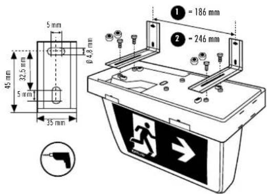
① = 186 mm ② = 246 mm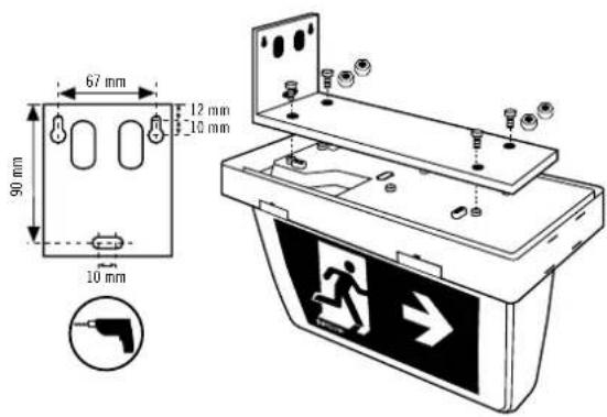
text_image
67 mm 12 mm 10 mm 90 mm 10 mmABB. • FIG. • PNC. 10
text_image
45 mm 32.5 mm 5 mm 35 mm 0.48 mm 1 = 186 mm 2 = 246 mmABB. • FIG. • PHC. 11 ABB. • FIG. • PHC. 14
text_image
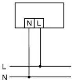
N L L NABB. • FIG. • PHC. 12
| X* | 180A | ***E |
ABB. • FIG. • PNC. 13
text_image
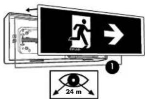
Diagram illustrating a person running on a 24-meter distance via a monitor, with directional arrows and eye symbol.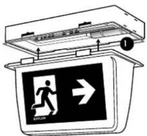
text_image
Diagram showing a person running inside an emergency exit device with directional sign and label '1'
text_image
Diagram of a life insurance device with pictogram and directional arrow indicating emergency exit or travelABB. • FIG. • PNC. 15 ABB. • FIG. • PNC. 16
text_image
Diagram showing a device with labeled components and directional arrows, likely illustrating a system or installation process.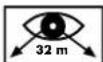
text_image
Technical diagram of a device with labeled components and directional arrows indicating flow or movementABB. • FIG. • PNC. 17 ABB. • FIG. • PNC. 18
17.117.2

natural_image
Pure technical diagram of a rectangular device with internal components and no visible text or symbols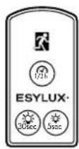
text_image
SARL →ABB. • FIG. • PNC. 19
natural_image
Illustration of a smartphone with a scroll and directional arrows indicating motion (no text or symbols)
Congratulations on your purchase of this high-quality ESYLUX product. To ensure correct device operation, please read these installation/operating instructions carefully and keep them in a safe place for future reference.
1 • SAFETY INSTRUCTIONS

WARNING! Work on electrical systems must be carried out by authorised personnel only, with due regard to the applicable installation regulations. Switch off the power supply before installing the system.
Use this product only as intended (as described in the user instructions). Do not make any changes or alterations as this will render any warranties null and void. You should check the device for damage immediately after unpacking it. If there is any damage, you should not install the device under any circumstances.
If you suspect that safe operation of the device cannot be guaranteed, you should turn the device off immediately and make sure that it cannot be operated unintentionally.

NOTE: this device must not be disposed of as unsorted household waste. Used devices must be disposed of correctly. Contact your local town council for more information.

NOTE: used batteries must not be disposed of as unsorted household waste. Used batteries must be recycled and may be returned free-of-charge to the place of sale. Batteries contain substances which are harmful to the environment and to human health and must therefore be disposed of correctly.
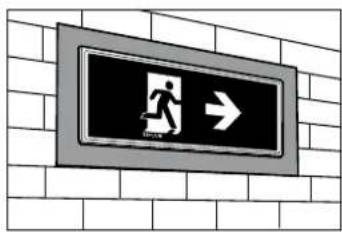
2 • DESCRIPTION
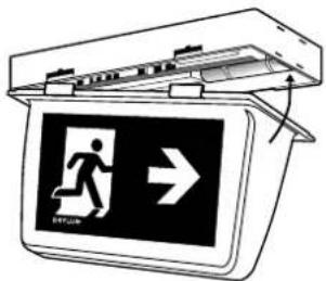
In the event of a power failure, single-battery emergency lights indicate/illuminate emergency exits for at least 3 or 8 hours (depending on the type).
The SLX/ELX series is designed for wall surface mounting or ceiling mounting (Fig. 1).
Other installation types are possible with separate accessories (see Chapter 4).
This light contains built-in LED lamps. The lamps in the light cannot be replaced.
3 • INCLUDED IN DELIVERY
SLX 14 / 24 LEDi Flat... containing:
1x emergency light including LED illuminant, installation set, rechargeable battery, screws for mounting accessories, spacer, IP 54 seal and symbols
Symbols included


SLX 24 / 32 LEDi High Cover... containing:
1x emergency light including LED illuminant, installation set, rechargeable battery, screws for mounting accessories, spacer, IP 54 seal and symbols
Symbols included


SLX 24 / 32 LEDi Display... containing:
1x emergency light including LED illuminant, installation set, rechargeable battery, screws for mounting accessories, spacer and centring pin (Fig. 15.1)

NOTE: Order pictogram panels separately.
ELX 20 LEDi Flat.... containing:
1x emergency light including LED illuminant, installation set, rechargeable battery, screws for mounting accessories, spacer and IP 54 seal
4 • ACCESSORIES

NOTE: The accessories required for the various installation types can be found on our website: www.esylux.com
5 • ELX PLANNING AIDS
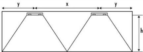
Distance dimension diagram (emergency exit/aisle width 2 m) see Fig. 2.
h = installation height
y = distance at end of lighting system
x = distance between lights
Support table for determining the wall/light and light/light distances to comply with a service value of 1 lux in accordance with EN 1838.
| Emergency light model Distance Ceiling mounting - Installation height (h) | ||||
| ELX 20 3h | x 9.00 m 9.50 m 10.00 m | |||
| y 4.00 m 4.50 m 5.00 m | ||||
| ELX 20 8h | x 5.50 m 6.00 m 6.50 m | |||
| y 2.50 m 2.50 m 2.50 m | ||||
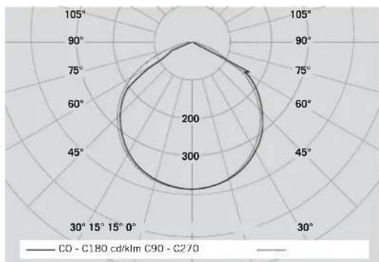
For your light planning projects, using software programs such as Relux ^10 , you can download photometric data from www.esylux.com
ELX polar diagram see Fig. 3.
6 • ASSEMBLY/INSTALLATION/CONNECTION
Please observe the following before installing the device:
- Switch off the power supply at the mains before installing the product.
• The light should only be installed on a stable, flat surface.
• Refer to the planning aids for ELX products (see Chapter 5).
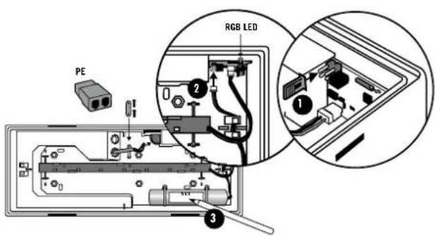
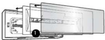
• Take note of the viewing distances of the SLX products when selecting the installation location. - Set the operating mode of the emergency light using a jumper before installing the device (Fig. 4.1), with jumper = standby mode / without jumper = continuous mode (default setting).

NOTE: After connecting the electrics, enter "0" in the 2nd field of the sticker (Fig. 12) for standby mode, or a "1" for continuous mode (EN 60598-2-22).
- Connect the rechargeable battery to the emergency light before installing the device (Fig. 4.2).

NOTE: Note down the installation date on the battery type plate (Fig. 4.3). The emergency lights are supplied with discharged batteries and must be connected to the mains for at least 20 hours to achieve full operational capacity.

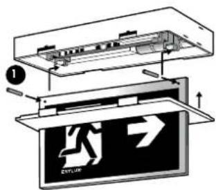
NOTE: The seal must be inserted for protection type IP 54 (Fig. 13.1 / 14.1 / 16.1).
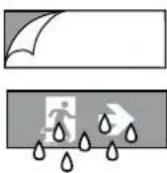
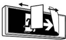
- Positioning the symbol sheets (Fig. 19).
After pulling off the backing paper, the self-adhesive symbol sheets can be easily positioned on the luminaire cover by wetting the adhesive surface with water. Any moisture or air trapped inside can be pressed out using a squeegee, working from the middle towards the edges.
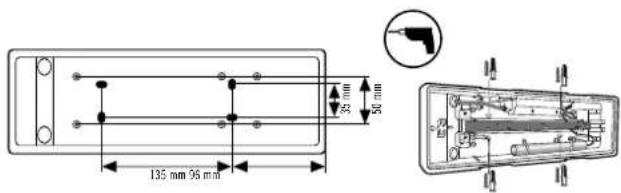
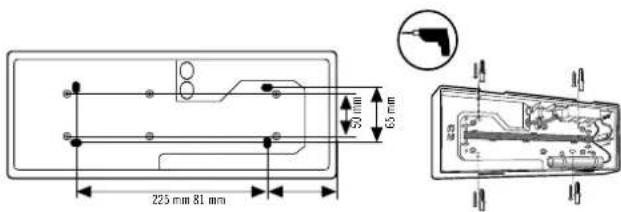
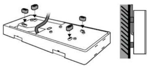
The SLX/ELX series is mounted on the ceiling or wall, as shown in Fig. 5 /Fig. 6. Spacers are available for surface-mounted cable inlets (Fig. 7).
Fig. 5: SLX 14 LEDi Flat... / SLX 24 LEDi High Cover... / SLX 24 LEDi Display...
Fig. 6: ELX 20 LEDi Flat... / SLX 24 LEDi Flat... / SLX 32 LEDi High Cover... / SLX 32 LEDi Display...
Other installation types are possible with separate accessories:
- Pendulum mounting with accessories (tube or cable for pendulum mounting) (Fig. 8)
• Wall bracket mounting with wall bracket accessories (Fig. 9) - Recessed wall/ceiling mounting with universal installation frame accessories (Fig. 18)
• Wall bracket mounting with wall mounting bracket 110 accessories (Fig. 10)
Connect the electrics in accordance with Fig. 11.

NOTE: 230 V AC 50 Hz must be permanently connected to ensure that the batteries are continuously charged. Before activation, connect the battery connector to the electronics (Fig. 4.2).
Cover installation depending on the model:
• SLX 14 LEDi Flat... / SLX 24 LEDi Flat... see Fig. 13
• SLX 24 LEDi High Cover / SLX 32 LEDi High Cover... see Fig. 14
• SLX 24 LEDi Display / SLX 32 LEDi Display.... see Fig. 15
• ELX 20 LEDi Flat... see Fig. 16
7 • AUTOMATIC SELF-TEST
The automatic self-test independently checks the availability of the electronics and battery charge. 20 hours after mains connection, a function test is automatically carried out. (Items tested: switching and illuminant, duration of test: 30 seconds). After another 4 hours, an operation endurance test is automatically carried out for 3 hours.
After the first operation endurance test, regardless of whether the test was successful or not, the weekly cycle (switching and illuminant function test) and six-monthly cycle (3-hour operation endurance test) will start automatically.
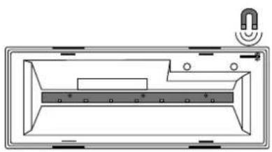
Test contact and remote control functions:
The test contact is triggered by means of a magnet (Fig. 17.1).
| Test contact (Fig. 17.1) Remote | controlMobil-SLI (Fig. 17.2) | LEDgreen | LEDblue | Condition |
| no action | lightsup | rechargeablebattery OK, mainsoperation, no faults,charge OK | ||
| press for approx. 1 sec. |  | flashes | short test, emergencyoperation 5 sec. | |
| press for approx. 3 sec. |  | flashes | function test, emergencyoperation 30 sec. | |
| press for approx. 5 sec. flas |  | operation endurancetest 1 hour/3 hours | ||
| press again forapprox. 5 sec. |  pressagain pressagain | operation endurancetest cancellation |
If the operation endurance test is triggered accidentally, it can be cancelled by pressing the test contact again for 5 seconds (or the Mobil-SLi remote control button Ⓜ (Fig. 17)).
RGB LED status indicator:
| LED green LED blue | LED red Condition | ||
| lights up mains operation/no fault | |||
| flashes battery charge | |||
| lights up power | failure/emergency | light operation | |
| flashes function | test/operation endurance test | ||
| lights up | function test/operation endurance test failed | ||
| flashes battery/charge faulty | |||

NOTE: The status indicator can only be deleted after the fault has been repaired, the mains have been reconnected and a function test has been performed.
8 • REPLACING THE BATTERY

NOTE: Please follow the safety instructions (see point 1: "Safety instructions").

NOTE: An SLX battery is not to be used in an ELX emergency light, as this could damage the device!
If the battery is faulty, it must be replaced. Only use the manufacturer's original batteries. The original batteries come with a polarised connection system. Write the installation date on the battery set.
9 • MAINTENANCE
Observe the regulations and norms when testing the lights.
Tests are required by law according to VDE 0100-718 (EN 50172).
10 • ESYLUX MANUFACTURER'S GUARANTEE
ESYLUX products are tested in accordance with applicable regulations and manufactured with the utmost care. The guarantor, ESYLUX Deutschland GmbH, Postfach 1840, D-22908
Ahrensburg, Germany (for Germany) or the relevant ESYLUX distributor in your country (visit www.esylux.com for a complete overview) provides a guarantee against manufacturing/material defects in ESYLUX devices for a period of three years from the date of manufacture.
This guarantee is independent of your legal rights with respect to the seller of the device.
The guarantee does not apply to natural wear and tear, changes/interference caused by environmental factors or damage in transit, nor to damage caused as a result of failure to follow the user or maintenance instructions and/or as a result of improper installation. Any illuminants or batteries supplied with the device are not covered by the guarantee.
The guarantee can only be honoured if the device is sent back with the invoice/receipt, unchanged, packed and with sufficient postage to the guarantor, along with a brief description of the fault, as soon as a defect has been identified.
If the guarantee claim proves justified, the guarantor will, within a reasonable period, either repair the device or replace it. The guarantee does not cover further claims; in particular, the guarantor will not be liable for damages resulting from the device's defectiveness. If the claim is unfounded (e.g. because the guarantee has expired or the fault is not covered by the guarantee), then the guarantor may attempt to repair the device for you for a fee, keeping costs to a minimum.
• TECHNICAL DATA
| SLX 14 LEDi Flat... SLX 24 | LEDi Flat... SLX 24 LEDi High Cover... | SLX 32 LEDi High Cover... | SLX 24 LEDi Display... SLX 32 LEDi Display... ELX 20 LEDi Flat... | |||||||||||
| EMERGENCY LIGHT DURATION | 3 hours | 8 hours | 3 hours | 8 hours | 3 hours | 8 hours | 3 hours | 8 hours | 3 hours | 8 hours | 3 hours | 8 hours | 3 hours | 8 hours |
| VIEWING DISTANCE | 14 m | 24 m | 24 m | 32 m | 24 m | 32 m | - | |||||||
| ILLUMINANT LED (included) | ||||||||||||||
| NiCd-BATTERY 3.6 V / 800 mAh 3.6 V / 1,800 mAh | ||||||||||||||
| MAINS VOLTAGE 230 V | ~ 50 Hz | |||||||||||||
| APPROX. POWER CONSUMPTIONA) STANDBY MODEB) STANDBY MODE WITH BATTERY CHARGINGC) CONTINUOUS OPERATIOND) CONTINUOUS OPERATION WITH BATTERY CHARGING | A) 1.45 WB) 2.41 WC) 3.27 WD) 4.14 W | |||||||||||||
| AMBIENT TEMPERATURE (IN OPERATION) | 5 °C to +35 °C | |||||||||||||
| PROTECTION TYPE/CLASS | IP 54 / II | IP 20 / II | IP 54 / II | |||||||||||
| CHARGE TIME | 20 hours | |||||||||||||
| INSTALLATION TYPE | Wall surface mounting/ceiling mounting. With accessories: recessed, recessed ceiling, wall bracket, pendulum set mounting | |||||||||||||
| HOUSING MATERIAL | Polycarbonate | |||||||||||||
| COLOUR | white, similar to RAL 9016 | |||||||||||||
| APPROX. DIMENSIONS | h 108 x w 328 x d 46 mm | h 148 x w 388 x d 46 mm | h 206 x w 328 x d 108 mm | h 231 x w 388 x d 148 mm | h 195 x w 328 x d 108 mm | h 223 x w 388 x d 148 mm | h 46 x w 388 x d 148 mm | |||||||
| SYMBOL HEIGHT | 90 mm | 120 mm | 120 mm | 160 mm | 120 mm | 160 mm | - | |||||||
| LUMINOUS FLUX ELX 3h / 8h | - | 186 lm | 60 lm | |||||||||||
Technical and design features may be subject to change. You can find out more about this product on the ESYLUX homepage.