
CKB840ONY - Cooker Pelgrim - Free user manual and instructions
Find the device manual for free CKB840ONY Pelgrim in PDF.
| Product type | Ceramic hob |
| Brand | Pelgrim |
| Model | CKB840ONY |
| Number of cooking zones | 4 Hi-Light zones |
| Front left zone | 210/120 mm, 2.2 kW |
| Rear left zone | 145 mm, 1.2 kW |
| Rear right zone | 180 mm, 1.8 kW |
| Front right zone | 145 mm, 1.2 kW |
| Total connected power | 6.4 kW |
| Supply voltage | 230 V / 400 V 2N AC, 50 Hz |
| Control type | Rotary knobs (continuous or stepped control) |
| Appliance dimensions (W x D x H) | 600 x 510 x 55 mm (approx.) |
| Cutout dimensions | 560 x 490 mm |
| Net weight | Approx. 10 kg |
| Control indicator | Red, lights up when a zone is on |
| Residual heat indicator | Lights up as long as the zone > 50°C |
| Double ring function | Front left zone with 2 concentric rings |
| Surface material | Ceramic glass |
| Recommended cleaning | Special ceramic glass cleaner, scraper for residues |
| Impact protection | Moderate impact resistant surface |
| Important note | Do not use if the surface is cracked or broken |
| Built-in installation | Possible in worktop thickness 30-40 mm |
| Electrical connection | By qualified installer, with proper protection |
Frequently Asked Questions - CKB840ONY Pelgrim
User questions about CKB840ONY Pelgrim
0 question about this device. Answer the ones you know or ask your own.
Ask a new question about this device
Download the instructions for your Cooker in PDF format for free! Find your manual CKB840ONY - Pelgrim and take your electronic device back in hand. On this page are published all the documents necessary for the use of your device. CKB840ONY by Pelgrim.
USER MANUAL CKB840ONY Pelgrim
natural_image
Simple diagram with five circles and a small square, no text or symbols present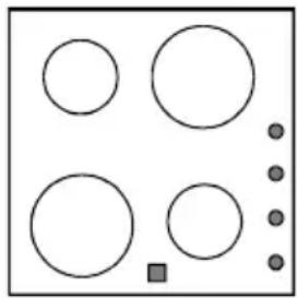
natural_image
Simple diagram with six circles and one square, no text or symbols presentnatural_image
Simple geometric shape with four gray circles inside a white rounded square (no text or symbols)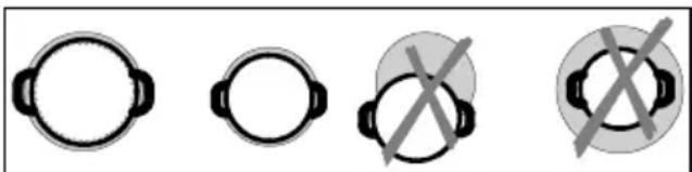
natural_image
Four circular icons with black connectors and crossed-out symbols, no text or labels presentnatural_image
Abstract pattern of curved white lines on a black background, resembling stylized waves or concentric arcs (no text or symbols)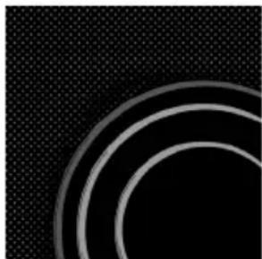
natural_image
Abstract pattern of concentric white circles on a black textured background (no text or symbols)natural_image
Abstract black-and-white pattern with concentric circular lines and scattered particles (no text or symbols)
natural_image
Illustration of a white tool hitting a dark circular surface with abstract patterns (no text or symbols)natural_image
Close-up of concentric circular white lines on black background, no text or symbols visibleafbeelding 5
natural_image
Diagram showing a 3D object being cut with an arrow, alongside a magnified view of the edge detail (no text or symbols)text_image
Diagram showing electrical connections with labeled components and directional arrows, including a device with switches and a power outlet.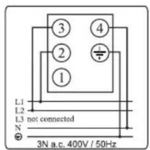
text_image
L1 L2 L3 not connected N 3N a.c. 400V / 50Hz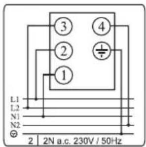
text_image
L1 L2 N1 N2 ① ② ③ ④ 2 N a.c. 230V / 50Hz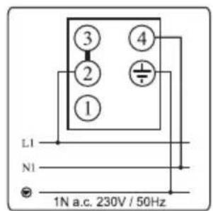
text_image
L1 N1 1N a.c. 230V / 50Hz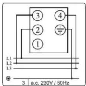
text_image
L1 L2 L3 ① ② ③ ④ 3 | a.c. 230V / 50HzOPMERKING
Instructions de raccordement
natural_image
Simple diagram with five circles and a small square, no text or symbols present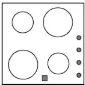
natural_image
Simple diagram with six circles and a small square, no text or symbols presentCommande des foyers
text_image
0 1 2 3 4 5 6 7 8 9 ©natural_image
Simple geometric shape with four gray circles inside a white rounded square (no text or symbols)Batterie de cuisine
natural_image
Four circular icons with different symbols: two black and one crossed with a cross, no text or labels present.natural_image
Abstract black background with curved white lines and faint diagonal marks (no text or symbols)fig. 1 fig. 2
natural_image
Abstract pattern with concentric curved lines on a black textured background (no text or symbols)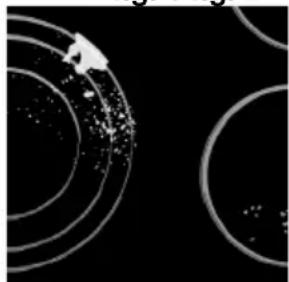
natural_image
Abstract pattern of concentric white circles on black background, no text or symbols presentfig. 3 fig. 4
natural_image
Abstract graphic with a white tool and dark circular patterns on black background (no text or symbols)
natural_image
Abstract circular pattern with concentric rings and a diagonal line, no text or symbols presentfig. 5
natural_image
Diagram showing a 3D object being cut with an arrow, alongside a magnified view of the edge detail (no text or symbols)text_image
Diagram showing electrical connections with labeled components and directional arrows, including a device with bulbs and a plug.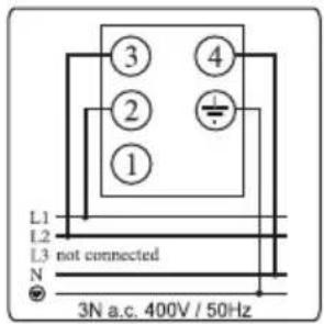
text_image
L1 L2 L3 not connected N 3N a.c. 400V / 50Hz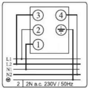
text_image
L1 L2 N1 N2 ① ② ③ ④ 2 N a.c. 230V / 50Hz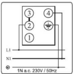
text_image
L1 N1 1N a.c. 230V / 50Hz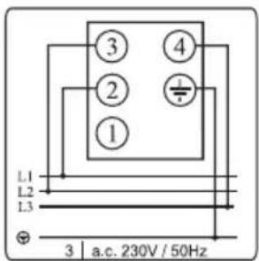
text_image
L1 L2 L3 ① ② ③ ④ a.c. 230V / 50HzNB
natural_image
Two identical diagrams showing circles and dots in different configurations, no text or symbols present.natural_image
Simple geometric shape with four gray circles inside a white rounded square (no text or symbols)natural_image
Four circular icons with different symbols: two black and one crossed with a cross, no text or labels present.natural_image
Abstract black background with curved white lines and faint diagonal strokes (no text or symbols)Abb. 1 Abb. 2

natural_image
Abstract pattern with concentric white circles on a black textured background (no text or symbols)
natural_image
Abstract pattern of concentric white circles on black background, no text or symbols presentAbb. 3 Abb. 4
natural_image
Abstract graphic of a white tool hitting a dark circular pattern on black background (no text or symbols)
natural_image
Close-up of two curved, elongated white lines against a black background, resembling abstract or microscopic patterns (no text or symbols)Abb. 5
natural_image
Diagram showing a 3D object being cut with an arrow, alongside a magnified view of a rectangular object with a 23 mm dimension (no text or symbols)natural_image
Technical line drawing of a mechanical clamp or bracket assembly with a screwdriver (no text or symbols)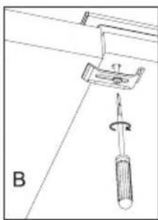
text_image
Btext_image
Diagram showing a device with labeled components and directional arrows, likely illustrating a system or installation process.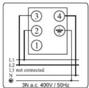
text_image
L1 L2 L3 not connected N 3N a.c. 400V / 50Hz
text_image
L1 L2 N1 N2 ④ ③ ② ① 2 N a.c. 230V / 50Hz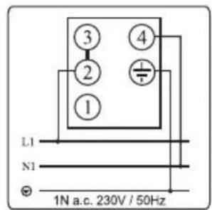
text_image
L1 N1 ① ② ③ ④ 1N a.c. 230V / 50Hz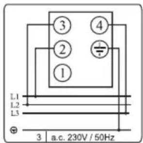
text_image
L1 L2 L3 ① ② ③ ④ 3 a.c. 230V / 50HzBEMERKUNG
Ceramic-glass Built-in Cooktop GB IE MT
Dear customer,
Ceramic-glass built-in cooktop is made for domestic use only.
Our products use environmentally friendly packaging, which can be either recycled or disposed of in an environmentally friendly manner.
To this end, individual packaging materials are clearly marked.
When your appliance finally wears out, please try not to burden the environment with it: call your nearest authorised service agent.
Instructions for Use
These instructions are intended for the user. They describe the cooker and how to use it. They also apply to different types of appliances, therefore you may find some descriptions of functions that may not apply to your appliance.
Instructions for Installation
This appliance should be connected to the power supply according to instructions for the connection of appliances in compliance with current standards and local regulations. The connection should be done by a qualified technician only.
Rating Plate
The rating plate with basic data is fixed on the rear wall of the appliance.
Fire hazard protection
Appliances are allowed to be mounted on one side next to a high kitchen cabinet, the height of which may exceed that of the appliance. On the opposite side however, only a kitchen cabinet of equal height as the appliance is allowed.
Attention...... 28
Technical Data 28
Glass Ceramic Cooktop...... 29
Setting of Cooking Zones 29
The Circuit and Extended Circuit Switch Signal lamp
Warning lamps "HOT"
Pots and Pans 30
Energy Saving Tips
Cleaning and maintenance of ceramic-glass hob....31
Mounting the Built-in Hob......32
Installing the foam gasket......32
Mounting dimensions....33
Electrical connections ......33
Connecting to Power Supply......34
Connecting diagram
Read the separate safety instructions before using the device!
The symbol on the product or on its packaging indicates that this product may not be treated as household waste. Instead it shall be handed over
to the applicable collection point for the recycling of electrical and electronic equipment. By ensuring this product is disposed of correctly, you will help prevent potential negative consequences for the environment and human health, which could otherwise be caused by inappropriate waste handling of this product. For more detailed information about recycling of this product, please contact your local city office, your household waste disposal service or the shop where you purchased the product.
Technical Data
| 048BKCepyTSVK65ES | |
| Mains voltage | 2N AC 400 V |
| Operating voltage | 230 V, 50 Hz |
| Type of control knobs E = sliding | increase of power with power regulators |
| Cooking zones(φ mm/kW) | HL =HI- light plate |
| Front left 210/120/2,2/HL | |
| Rear left | 145/1,2/HL |
| Rear right | 180/1,8/HL |
| Front right | 145/1,2/HL |
| Total power (kW) | 6,4 |
Glass Ceramic Cooktop
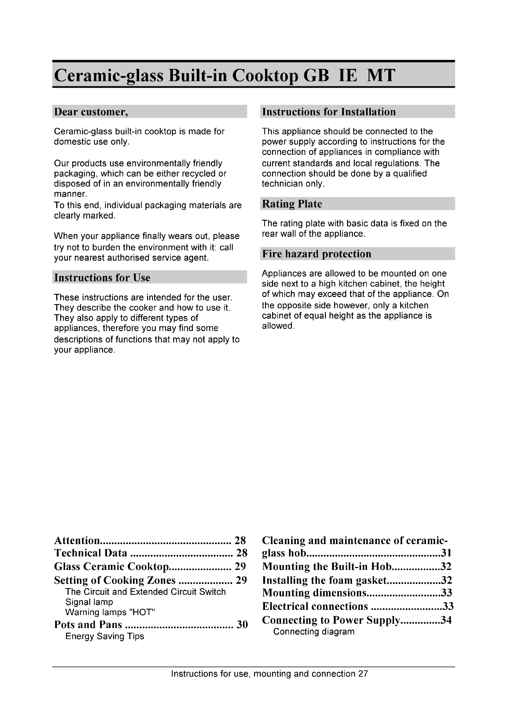
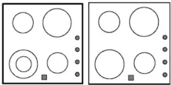
The glass ceramic cooktop has four heating zones. Its surface is flat and there are no edges where food remains usually collect.
- The heating zone reaches the preset temperature quickly, yet the area around the hot cooking zone remains cold.
- The hob is resistant to temperature changes.
- The ceramic hob is impact resistant. A dish can be placed on the hob a little harder and yet the surface will not be damaged.
- Never use the ceramic hob as a working surface. Sharp objects may scratch it.
- Preparation of food in aluminum or plastic dishes on hot cooking plates is not allowed. Do not place any plastic objects or aluminum foils upon the cooktop surface.
- Do not prepare coffe in small traditional coffe pots if the diameter of the pot is smaller than the cooking area as it may result in damage.
WARNING!
- Never use a cracked or broken ceramic hob. The hob may break or crack if an object with sharp edges falls on it. The crack may be
visible immediately or only after some time. Disconnect the appliance from mains immediately in case any cracks are detected upon the glass ceramic surface.
- If you spill sugar or any other sweet substance, wipe the hob immediately, with cloth or use a scraper even when the cooking area is still hot. This will prevent damage to it.
- Never use ordinary cleaning agents for cleaning the ceramic glass cooktop, as may damage the ceramic glass surface.
natural_image
Two identical diagrams showing circles and dots in different configurations, no text or symbols present.Setting of Cooking Zones
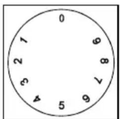
The cooking zones are controlled by knobs mounted on the control panel of the cooker. The heating degrees are marked on the knobs from 1 to 6 (gradual increase), or 1-9 (continuous increase), whereby position 1 is the lowest and position 6 or 9 respectively the highest setting. The heating is switched off in position 0. The intermediate settings can also be selected and set in two ways: in stages or continuously. The knob can be turned in both directions. Energy knobs increase power if turned clockwise and decrease if turned in opposite direction.
Use of Cooking Zones
E
0 Cooking zone switched off
1-2 Maintaining the temperature and warming up smaller quantities of food
3-4 Warming up
5-6 Warming up or slow cooking of large quantities of food
7 Baking in turns (like pancakes..)
8 Frying
9 Quick heating up
text_image
0 1 2 3 4 5 6 7 8 9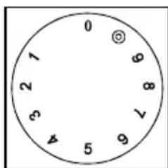
text_image
0 1 2 3 4 5 6 7 8 9 10The Circuit and Extended Circuit Switch
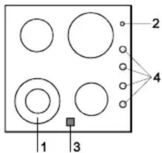
During normal turning of this knob, the basic plate is switched on first (inner circuit). To switch on the second and the extended circuit, turn the knob till the double circuit mark ◎ until “click” is heard and then turn it back to selected position.
To switch off the complete plate, simply turn the knob back to position 0.
1 double circuit cooking plate
2 control lamp ON
3 warning lamps "HOT"
4 setting knobs
text_image
1 2 3 4Signal lamp
Signal lamp ON (red) is on when at least one cooking plate is switched on.
Warning lamps "HOT"
Glass ceramic cookplates are equipped with warning lamps "HOT". The lamp, switched on at any particular time, signals that the relevant cookplate is hot (danger of burns). When the cookplate is switched off, the lamp remains on until the temperature of the cookplate falls below 50°C.
natural_image
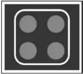
Simple geometric shape with four gray circles inside a white rounded square (no text or symbols)Pots and Pans
Use only high quality pots with flat and stable bottom.
- Always be careful to put the pot in the middle of the cooking zone.
- If you use the pots made of temperature resistant glass or earthenware, always consider the manufacturer's instructions.
- If you use a pressure cooker, never leave it unattended. Select the highest temperature setting, wait until the correct pressure is reached in the pressure cooker and turn the knob to a lower setting, as recommended by the manufacturer of the pot.
- When using high radiation (bright metal surface) crockery, or thick bottom dishes for preparing food on the glass ceramic hob, the period of reaching the boiling point may be prolonged for certain time (up to 10 minutes). Consequently, if you need to boil considerable amount of liquid, it is recommended to use the dark, flat bottom pot.
natural_image
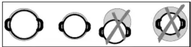
Four circular icons with different symbols: two with black connectors and one with crossed-out X (no text or labels)The cooker top can be damaged if:
- switched on and left uncovered or with an empty pot on it,
- if you use pots with an inadequate bottom like uneven, rough or too small diameter bottoms (traditional coffee pan).
- Never use the earthenware pots as they are very likely to scratch the ceramic glass surface.
- Before putting the pot on the hot plate, thoroughly wipe the bottom of the pot, to prevent heat conduction and to protect the hot plate.
Energy Saving Tips
- The bottom of the pot should be slightly concave for optimum heat transfer from the cooking zone.
- The bottom of the pot should always suit the size of the cooking zone. If the pot is smaller, it can cause energy loss and if larger, the cooking zone may become damaged.
- Use a pot lid whenever possible.
- The pot size should suit the quantity of food. Cooking smaller quantities of food in a large pot results in energy loss.
- Food which needs longer cooking may also be prepared in the pressure cooker.
- Various vegetables, potatoes, etc. can be cooked with a smaller quantity of water. This way the food is cooked much sooner, but do not forget to cover the pan properly. When the water starts boiling, turn the knob to the position for slow boiling.
- Some 5-10 minutes before the food is cooked, switch off the hot plate, whichever you are using.
Cleaning and maintenance of ceramic-glass hob
natural_image
Abstract pattern of curved white lines on black background, no text or symbols presentfig. 1 fig. 2
natural_image
Abstract pattern with concentric circular lines on a black textured background (no text or symbols)
natural_image
Abstract pattern of concentric white circles on black background, no text or symbols presentfig. 3 fig. 4
natural_image
Illustration of a white tool with a handle on a dark background, surrounded by faint circular patterns (no text or symbols)
natural_image
Close-up of concentric circular white lines on black background, no text or symbols visiblefig. 5
Ceramic glass hob should be cleaned only when completely cooled down, preferably after each use, otherwise even the slightest stains remaining after cooking may burn into the hob surface with each following use.
For regular maintenance of ceramic-glass hob use special cleansing agents, produced in such way to create protective film upon the surface.
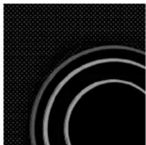
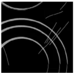
Before each use, wipe the dust and other particles from the hob - they may scratch the surface (Fig. 1).
Caution: use of steel wool, abrasive cleaning sponges, and abrasive detergents can scratch the surface of the hob. The surface may also be damaged by the use of aggressive sprays and inappropriate liquid chemicals (Fig.1 and 2).
Pattern marks can be erased by the use of aggressive cleansing agents or rough and damaged cookware bottoms (Fig. 2).
Minor stains are removed with moist soft cloth; after that the surface should be wiped dry (Fig. 3).
Water stains are removed with gentle vinegar solution, but you must not wipe the frame with it (certain models only), since it may lose its glow. Never use any aggressive sprays or limestone removers (Fig. 3).
Major stains are removed with special ceramic-glass cleansers. Follow strictly the manufacturer's instructions.
Be careful to remove any remains of cleansing agent from the hob surface, otherwise they will be heated during the next use and can damage the hob (fig. 3).
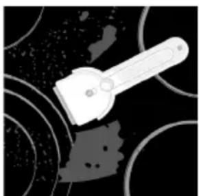
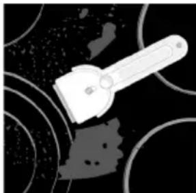
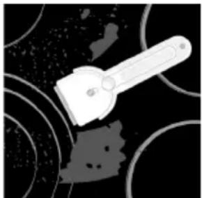
Stubborn and burnt stains are removed with special ceramic-glass scraper. Be careful, however, not to touch the hotplate surface with the scraper handle (Fig. 4).
Handle the scraper with utmost care to avoid injuries!
Sugar and sugar containing food may permanently damage the ceramic-glass hob surface (Fig.5), so the remains of sugar and sugar containing food must be scraped off from the hob surface immediately, when the hotplates are still hot (Fig. 4).
Discoloring of ceramic-glass hob has no effect whatsoever on its operation and stability. In most cases, it appears as the consequence of burnt in food remains, or as a result of dragging pots and pans (especially aluminum or copper bottom cookware) across the surface, and such discoloring is rather hard to remove.
Note: All described faults are mostly esthetical and do not affect directly the operation of the appliance. Remedy of such faults is not covered by warranty.
Mounting the Built-in Hob
- The plywood coating of the kitchen elements should be processed with temperature resistant adhesives (100°C), otherwise they may distort or change shape.
- The use of decorative trimmings made of solid wood on the worktop behind the cooking zone is allowed only in case the minimum distance is as marked on the drawings for mounting.
- Cut out the top panel of the kitchen unit into which the ceramic glass cooktop is to be built into.
-
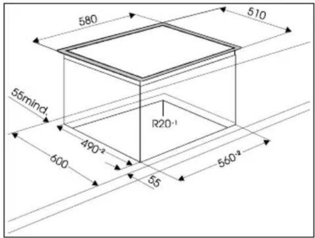
Minimum distance between the built-in cooktop and the rear wall is marked on the installation drawing.
-
Protect the edges of the openings, if necessary.
- Built-in cooktop may be mounted into 30 - 40 mm thick working tops.
- In case there is a drawer in kitchen cabinet under the built-in hob, it is necessary to install an additional horizontal barrier of height 6 cm under the hob and above the drawer.
Installing the foam gasket
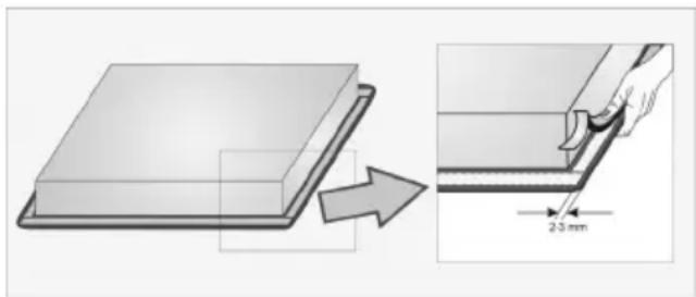
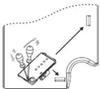
Before inserting the appliance into the opening in the kitchen worktop, the supplied foam gasket must be attached to the lower side of the glass ceramic (glass) cooking hob (see figure above). Do not install the appliance without the foam gasket!
The gasket should be attached to the appliance in the following way:
- Remove the protective film from the gasket.
- Then, attach the gasket to the lower side of the glass, approximately 2-3 millimetres from the edge (as shown in the figure). The gasket must be attached along the entire length of the glass edge and should not overlap at the corners.
- When installing the gasket, make sure that the glass does not come into contact with any sharp objects.
NOTE!
On some appliances the gasket is already installed!
natural_image
Diagram showing a 3D object being cut with an arrow, alongside a magnified view of a rectangular component with a 25 mm dimension label (no text or symbols on the object itself)Mounting dimensions
text_image
580 510 55mind. 490-2 R20-1 600 55 560-2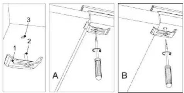
text_image
1 2 3 A B1 - Fixing bracket
2 - Screw
3 - Hole
A - Thin worktops
B - Thick worktops
- The worktop should be installed completely horizontally.
- The cutoff surfaces should be appropriately protected.
- Use the supplied screws [2] (4x - SVK6...600 mm; 6x - SVK7...750 mm;) to secure the fixing brackets [1] (4x - SVK6...600 mm; 6x - SVK7...750 mm;) to the bottom of the cooker where appropriate holes [3] have been prepared for this purpose.
- Insert the cooking hob into he cutoff and press it heavily from above against the worktop.
- For screwing down the fixing clip it is not allowed to use screws longer than 6.5 mm.
- Connect the cooking hob to the power mains (see instructions for connecting a cooking hob on a power network).
Electrical connections
- The electric built-in cooker has to be mounted and installed by a qualified technician. The protection of the electrical wiring shall comply with current standards and regulations.
- Before connecting the appliance to the power source, make sure that the voltage stated on the rating plate complies with the voltage of your power supply. The rating plate of the ceramic glass hob is fixed on the lower side of the hob.
• The cooker shall be connected to 230 V AC.
- Electric connections shall be of such design, to incorporate a protection device between the appliance and the supply, like fuses or FI switches (to assure at least a 3 mm clearance between the contacts in open position).
- The connection should be made considering the current capacity of the installation and the fuses.
- Fire protection is of class Y, which means that the appliance may be mounted between two kitchen units; one of them may be higher than the appliance itself, the other has to be of the same height.
- After mounting, the live parts and insulated parts of the appliance should be protected against accidental contacts.
- The distance between the ceramic glass hob and the hood should be at least as stated in the instructions for mounting the hood.
- No kitchen furniture drawers are allowed to be mounted below the glass ceramic cooktop.
Connecting to Power Supply
Power supply may be connected by the qualified technician only. Connecting sockets are available when you open the connecting box cover.
WARNING!
Before repairing or servicing, disconnect the power supply. According to the mains voltage the appliance should be connected in line with the displayed diagram. Protective conductor (PE) should be connected to the socket marked EARTH.
Connecting cable should be inserted through the clamp device to prevent eventual pullout. Upon completed power connection switch all hotplates for about 3 minutes to check they function properly.
Connecting diagram
text_image
Diagram showing a device with light bulbs and directional arrows, possibly indicating a system or process flow.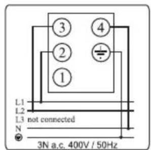
text_image
L1 L2 L3 not connected N 3N a.c. 400V / 50Hz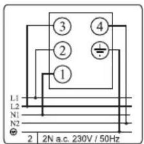
text_image
L1 L2 N1 N2 ④ ③ ② ① 2 N a.c. 230V / 50Hz
text_image
L1 N1 ① ② ③ ④ 1N a.c. 230V / 50Hz
text_image
L1 L2 L3 ① ② ③ ④ a.c. 230V / 50HzNOTE
In some connection boxes the connector bridges are placed between contacts 2 and 3, and in the others they are stored at a designated place within the box. These boxes have the connection screws already in open position so they need not be unscrewed. During the tightening procedure you will hear a faint "click", meaning that the tightening screw should be fastened tightly all the way
Connection may be carried out by means of:
- rubber coated connection cables, model H05 RR-F 4x1,5 with yellow-green earthing cable;
- PVC insulated connection cables, model H05 VV-F 4x1,5 with yellow-green earthing cable; or
- any other suitable cables.
WE RESERVE THE RIGHT TO ALTER THE SPECIFICATIONS WITH NO INFLUENCE TO THE OPERATION OF THE APPLIANCE.
natural_image
Warning symbol with exclamation mark inside a triangle (no text or numbers)plak hier het toestel-identificatieplaatje placez ici la plaque d'identification de l'appareil kleben Sie hier das Gerätetypenschild ein stick the appliance identification card here
Dit plaatje bevindt zich aan de bovenzijde van het toestel. Cette plaque se trouve sur le dessus de l'appareil. Dieses Schild befindet sich an der Oberseite des Gerätes. This card is located on the top of the appliance.