IAN 282088 - Jack ULTIMATE SPEED - Free user manual and instructions
Find the device manual for free IAN 282088 ULTIMATE SPEED in PDF.
| Product type | Rolling hydraulic jack |
| Brand | Ultimate Speed |
| Model | IAN 282088 |
| Maximum load capacity | 1500 kg |
| Lifting height | 90 - 358 mm |
| Hydraulic oil type | SAE 10 |
| Hydraulic oil quantity | 105 ml |
| Maximum actuation force | 350 N |
| Intended use | Lifting and lowering vehicles |
| Operating temperature | -20°C to +40°C |
| Safety standard | EN 1494/A1:2008 |
| Warranty | 3 years |
| Weight | Not specified |
| Dimensions (L x W x H) | Not specified |
| Color | Not specified |
| Package contents | Hydraulic jack, lifting bar (2 pieces), instruction manual |
| Maintenance and cleaning | Lubricate moving parts, wipe with an oiled cloth, do not use aggressive detergents |
| Main safety instructions | Use on a flat surface, never exceed the rated load, do not work under the vehicle without axle stands, close the valve after use |
| Spare parts and repairability | Repair only by a specialist, do not disassemble yourself, oil draining/filling by qualified personnel |
Frequently Asked Questions - IAN 282088 ULTIMATE SPEED
User questions about IAN 282088 ULTIMATE SPEED
0 question about this device. Answer the ones you know or ask your own.
Ask a new question about this device
Download the instructions for your Jack in PDF format for free! Find your manual IAN 282088 - ULTIMATE SPEED and take your electronic device back in hand. On this page are published all the documents necessary for the use of your device. IAN 282088 by ULTIMATE SPEED.
USER MANUAL IAN 282088 ULTIMATE SPEED
Operation and Safety Notes
Translation of the original instructions
NL BE
HYDRAULISCHBRANGEERKRIK
GB/IEOperation and Safety NotesPage 11
Proper use. Page 12
Description of parts.. Page 12
Technical data.. Page 12
Included items.. Page 12
Safety notes.. Page 12
Before first use
Handle assembly . Page 13
Distribution of the hydraulic oil.. Page 14
Using the jack.. Page 14
Raising the vehicle. Page 14
Lowering the vehicle. Page 14
Cleaning and care
Maintenance and service.. Page 14
Air purge procedure Page 14
Disposal
Translation of the original Conformity Declaration
Warranty
Hydraulic Trolley Jack
Introduction
We congratulate you on the purchase of your new product. You have chosen a high quality product. Familiarise yourself with the product before using it for the first time. In addition, please carefully refer to the operating instructions and the safety advice below. Only use the product as instructed and only for the indicated field of application. Keep these instructions in a safe place. If you pass the product on to anyone else, please ensure that you also pass on all the documentation with it.
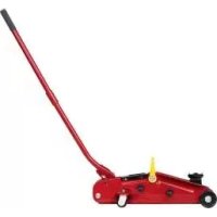
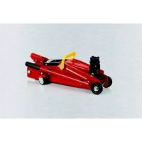
Properuse
The hydraulic vehicle jack is intended for raising and lowering motor vehicles. Other uses or modification of the hydraulic vehicle jack shall be considered as improper use and may lead to injury or damage. The manufacturer will not accept liability for loss or damage arising from improper use. The product is not intended for commercial use.
Note: Reclose the release valve 5 after each use!
Description of parts
Lifting handle (2 parts)
Lifting arm
3 Support plate
4 Carrying handle
5 Release valve
Lifting handle socket
7 Knurled screw
Relief valve
9 Saddle
-Technicaldata
Stroke:90-358mm
Maximum load: 1500kg
Hydraulic oil
grade: SAE 10
Hydraulic oil
quantity: 105ml
Maximum
force on lever: 350 N
IncludedItems
1 hydraulic trolley jack
1 lifting handle (2 parts)
1 operating instructions

Safety notes
DANGER! Follow the instructions below to avoid the threat of loss of life, injury, or damage to the product etc.
Always use axle stands and wheel chocks in addition to your hydraulic vehicle jack.
Never work under a raised vehicle unless you have taken additional safety precautions. This is intended to prevent the vehicle from rolling away, sliding off or overturning the jack.
Use the product on a solid, level surface only. Using the product on an unstable or uneven surface - such as a gravel surface - may lead to the load slipping.
1500 1 k
The person operating the jack must observe the jack and the load during all movements.
Never work under the raised load if it has not been made secure by suitable means.
Do not allow the hydraulic vehicle jack to be used by uninstructed or inexperienced persons.
Before using the hydraulic vehicle jack take precautions to prevent the vehicle from rolling away. Put the handbrake on, place the vehicle
in gear (with automatic gearboxes set to "P") and chock the wheels.
Even with safety measures in place always remain alert and make a visual check that the support plate 3 is firmly seated against the vehicle jacking point.
Make sure that no petrol, battery acid or any other dangerous substance can flow out of the vehicle when the vehicle is being lifted.
Check that no person or object is under the vehicle before you lower it.
Lower the vehicle slowly.
Check that all parts have been assembled and fitted properly and are undamaged.
Before each use check that the hydraulic vehicle jack is working properly. Check the screws and valves of the hydraulic vehicle jack for correct seating and look out for hydraulic oil leaks in particular.
Never use the hydraulic vehicle jack for moving or loading a vehicle. Never use it to lift a whole vehicle completely off the ground.
t's not allowed to lift up people with the hydraulic jack and make sure that near located people keep enough distance to the vehicle when the hydraulic jack is in use.
Never change the setting of the safety valve 8. It has been set at the factory and must not be adjusted. Stop using the product if the safety valve setting is changed.
Before using the vehicle jack, the user must be made familiar with the device by an experienced person. The pump force and the transferred force are equal to approximately 350 N.
If the markings on the product are damaged enough so as to be illegible then the vehicle jack must not be used until the markings are renewed.
No modifications may be carried out to the hydraulic trolley jack. Any physical modification of the device has an effect on the safety of the device and its compliance with EN 1494/A1:2008.
The applied force when using the vehicle jack must be lower 350N . The equates to a force on the lever of approximately 35kg .
If you find it difficult to pump up the hydraulic jack, ask another person for help.
The operating temperature of the hydraulic oil of this equipment is between -20^ to +40^ . Otherwise, the hydraulic jack may not operate correctly, which may cause the jack to slip and the vehicle may fall off, causing unnecessary damage to the car and the hydraulic jack.
Only use this device to lift and lower the vehicle, not to keep the vehicle in a lifted position. Do not move it whilst raising or lowering.
After use return all parts used into their original position. Have the hydraulic oil or oil pump replaced by a professional if the parts can no longer be moved.
If you notice a spillage of oil, stop using the product and absorb the oil on the floor with a cloth. Any reparation must be done by a professional.
Before first use
- Handleassembly
Prior to assembly please remove the clip attached to the handle socket (see Fig. A). This piece it's there for shipping purposes only and is not part of the jack.
Refer to fig. B when performing this step. Push in the Spring Button located on handle piece "a" and insert handle "a" into handle "b". Please watch your fingers while perfor- ming this step, being careful not to get pinched.
Fully unfasten the knurled screw located in the handle socket to insert the assembled handle (see Fig. C).
Line up the square hole located at the bottom of the handle 1 over the square bolt inside the handle socket 6.
- Secure the handle 1 in place by tightening the knurled screw 7 in the handle socket 6.
Before …/Using the jack / Cleaning and care / Maintenance and service
Distribution of the hydraulic oil
With the release valve closed, insert the lifting handle into the lifting handle socket. Use at least 6 firm pumping movements to charge the hydraulic system (move lifting handle up and down). This action distributes the hydraulic oil evenly.
Note: Check that the release valve 5 is closed by inserting the lifting handle 1 and trying to turn it clockwise (see Fig. D). When you cannot turn it any further, the release valve 5 is closed.
Using the jack
Raising the vehicle
Close the release va by turning the handle 1 clockwise.
Place the hydraulic vehicle jack under one of the lifting positions as shown in the owner's manual supplied by the vehicle manufacturer.
Ensure that the support plate is centrally loaded. By moving the lifting handle up and down, raise the vehicle sufficiently to allow you to insert axle stands under the vehicle (see Fig. E).
Allow the vehicle to come down on to the axle stands by slowly opening the release valve 5 by turning the lifting handle 1 anticlockwise.
Lowering the vehicle
DANGER TO LIFE! Check that no person or object is under the vehicle before you lower it.
First raise the vehicle slightly (as described earlier) in order to be able to remove the axle stands.
Turn the release valve anticlockwise until the vehicle lowers, but do not turn it to the extent that it detaches or hydraulic oil leaks from the release valve (see Fig. F).
CAUTION! Lower the vehicle slowly, otherwise there is the danger of injury and damage to the product or to the vehicle.
Pull the trolley jack out from under the vehicle and fully lower the lifting arm 2.
Close the release valve by turning it clockwise.
- Cleaning and care
Never use harsh or corrosive cleaning agents.
Liberally grease all external moving parts.
Clean the hydraulic trolley jack using a slightly oily cloth.
Fully lower the lifting area and lifting handle sleeve to be able to store the trolley jack in the smallest possible space.

Maintenance and service
Note: Refilling or topping up with hydraulic oil may only be carried out by specialist personnel! Always use hydraulic oil that fulfils the specification for SAE 10. Please note that filling with too much oil may adversely affect the functioning of the vehicle jack. Fill with a maximum of 105ml oil when all the oil has been used. Fill the hydraulic oil reservoir up to the bottom edge of the filling opening (see Fig. G).
Air purge procedure
During shipment or after oil refill, air may get into the hydraulic system causing poor lifting performance. Then system air purge is required as follows:
- Turn the handle fully counterclockwise to fully open the release valve.
- Pump handle 1 rapidly several times.
- Turn the handle 1 clockwise to close the release valve 5
4.Pumphandle 1 until the litt arm2 reaches maximum height and continue to pump several times to remove trapped air in the ram.
.../ Disposal/ Translation of the original Conformity Declaration/Warranty
- Turn the handle 1 fully counterclockwise to lower litt arm 2 to lowest position. Use force on saddle 9 if necessary.
- Turn the handle 1 clockwise to close the release valve 5 and check for proper pump action. It may be necessary to perform the above steps more than once to assure air is evacuated totally.
Note:The Lifetime of three years expires, if the car jack get not checked by qualified specialist.
Defective hydraulic vehicle jacks must be repaired by a specialist workshop only. Never attempt to repair the hydraulic vehicle jack yourself.
Never take the hydraulic vehicle jack to pieces. Taking the vehicle jack to pieces yourself may result in it not working properly.
declaration refers, complies with the directive of 2006/42/EC.
Related harmonised standard: EN 1494 / A1:2008
Serial number: IAN 282088

Tobias Koenig
Division Manager
Neckarsulm, 14 Sept 2016
The complete declaration of conformity can be viewed at: www.owim.com
Disposal
The packaging and ancillary packing consist entirely of environmentally-friendly materials. They can be disposed of at your local recycling facility.
In the interest of the environment, do not throw out the product with your household refuse. Take it to a suitable centre where it can be disposed of properly. Your local council will be able to tell you where the collection centres are located and their opening times.
Dispose of the hydraulic oil in an environmentally compatible manner. Ask your local repair garage to see to its disposal or find your nearest waste materials collection centre.
Translation of the original Conformity Declaration
We, OWIM GmbH & Co. KG Stiftsbergstraße 1, DE-74167 Neckarsulm, GERMANY, hereby declare under our sole responsibility that the product: Hydraulic Trolley Jack, Model No.: HG01698, Version: 11/2016, to which this
Warranty
The product has been manufactured to strict quality guidelines and meticulously examined before delivery. In the event of product defects you have legal rights against the retailer of this product. Your legal rights are not limited in any way by our warranty detailed below.
The warranty for this product is 3 years from the date of purchase. Should this product show any fault in materials or manufacture within 3 years from the date of purchase, we will repair or replace it - at our choice - free of charge to you.
The warranty period begins on the date of purchase. Please keep the original sales receipt in a safe location. This document is required as your proof of purchase. This warranty becomes void if the product has been damaged, or used or maintained improperly.
The warranty applies to defects in material or manufacture. This warranty does not cover product parts subject to normal wear, thus possibly considered consumables (e.g. batteries) or for damage to fragile parts, e.g. switches, recharge
able batteries or glass parts.