
AC1004 - Industrial Automation IFM - Free user manual and instructions
Find the device manual for free AC1004 IFM in PDF.
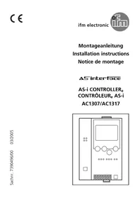
| Product Type | AS-i controller (AS-i master with preprocessing) |
| Brand | IFM |
| Model | AC1004 |
| Category | Industrial automation |
| Dimensions (L x H x D) | Approx. 100 x 75 x 50 mm (estimate) |
| Weight | Approx. 200 g (estimate) |
| Power supply | 24 V DC (via +24 V and 0 V terminals) |
| Protection | IP20, mounting in electrical cabinet |
| Mounting | On 35 mm rail (DIN) |
| Communication interfaces | RS232C and RS485 (up to 31 controllers in parallel) |
| Transmission speed | 4800 to 62400 baud (configurable via mode b) |
| Number of AS-i masters | 1 or 2 (depending on version) |
| Main functions | Control of sensor/actuator data exchange, preprocessing, standalone or gateway mode |
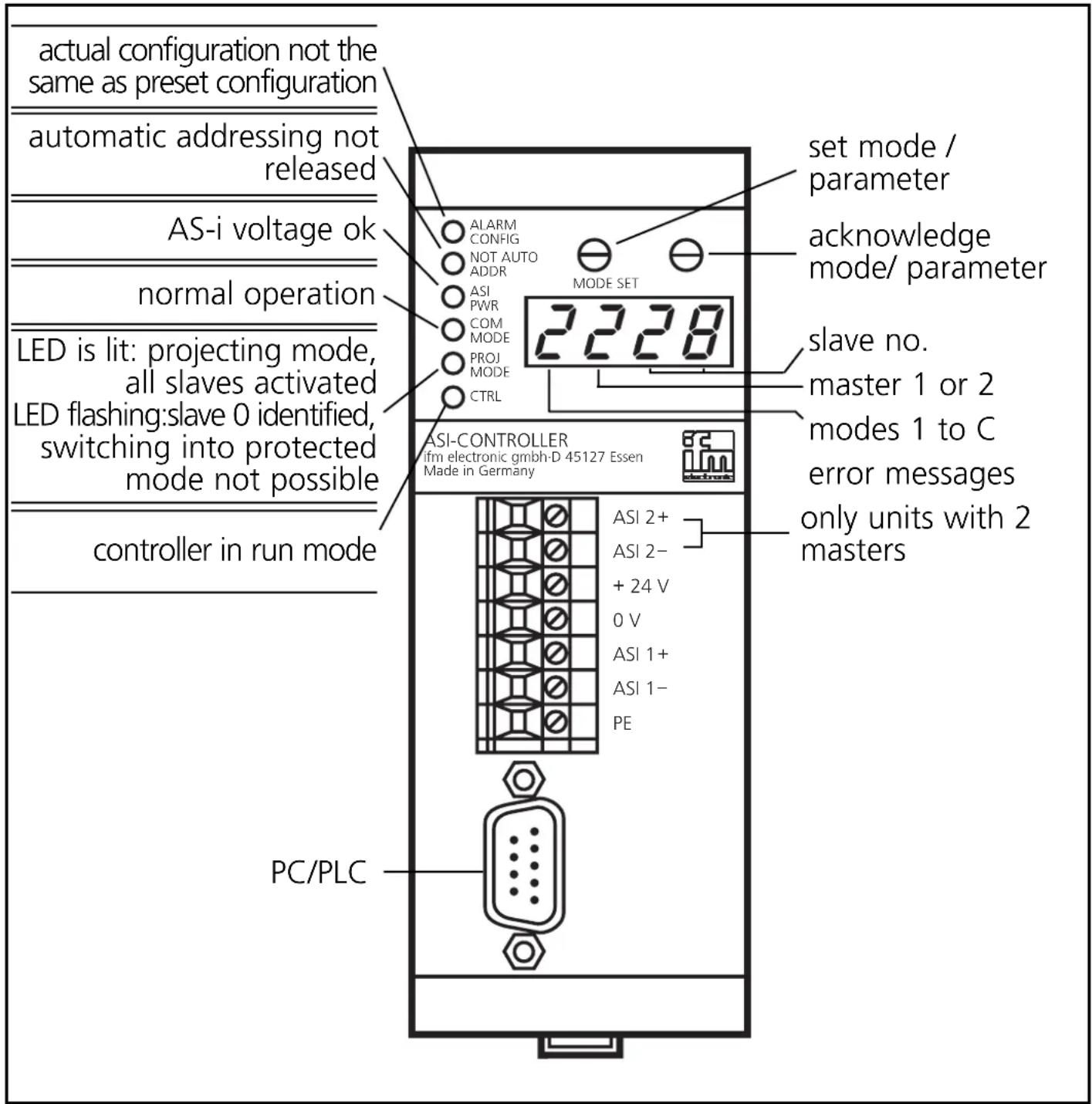
| Indicators | LEDs: ALARM, CONFIG, NOT AUTO, ADDR, ASI, PWR, COM, MODE, PROJ, MODE, CTRL; 4-segment display |
| Operating modes | Slave display, addressing, preselection, program stop/start, serial speed setting |
| Maintenance and cleaning | Avoid condensation, dust, vibrations; do not obstruct ventilation holes |
| Safety | Disconnect power before connection; do not connect negatives together or to ground; ensure good PE connection |
| Spare parts and repairability | Not specified; requires qualified intervention |
Frequently Asked Questions - AC1004 IFM
User questions about AC1004 IFM
0 question about this device. Answer the ones you know or ask your own.
Ask a new question about this device
Download the instructions for your Industrial Automation in PDF format for free! Find your manual AC1004 - IFM and take your electronic device back in hand. On this page are published all the documents necessary for the use of your device. AC1004 by IFM.
USER MANUAL AC1004 IFM
Functions and features
- The controller integrates 1 or 2 AS-i masters, a mini controller and a field bus interface as an option.
- it controls the data exchange to the sensor/actuator level
- it processes the peripheral data in the integrated processor (signal preprocessing)
- it works as stand-alone controller with data exchange to the PC (visualisation).
- it communicates with the higher-level control system (in the gateway mode)
Programming interface RS232C
- baud rate 4800 to 62400 baud
- max. distance between controller and host: 20m
- no potential separation from the controller supply
- pin connections: pin2: Rxd; pin 3: Txd; pin 5: Gnd
Programming interface RS485
- baud rate 4800 to 62400 baud
- max. distance between controller and host: 1000m
- potential separation from the controller supply
- up to 31 controllers connected in parallel
- pin connections: pin3: signal B; pin 8: signal A
For the programming of an R485 controller the RS232C/RS485 converter (order no. E70071) is necessary in addition to the programming cable (order no. AC4010).
Mounting
Mount the controller onto a 35mm rail. The unit has protection IP20, therefore it should be mounted in a protected place (e.g. switching cabinet).

Ensure a condensation-free environment. Avoid excessive dust, vibration and shock. The circulation of air through the vents must not be hampered.
Electrical connection

Disconnect power. Connect the unit according to the terminal marking. Never connect the minus potentials to each other or the minus potentials and the PE connection.
Ensure an electrically safe ground connection between the AS-i controller (PE terminal) and the ground connection of the unit.
The RS485 cable must be operated with a terminating resistor at both ends because the cable driver is switched with a high-ohmic value in the quiescent condition and in case of a high signal.
Cables A and B are connected via a 120Ω resistor. Cable A is connected to +5V via 330Ω and cable B to OV via 330Ω.
These resistors are already integrated in the AS-i controller. They can be activated via links between pins 5-9, 8-7 and 1-6 in the terminating plug.
After application of the supply voltage all the LEDs and the LED display are switched on (LED test); then the version numbers of the hardware and the software are displayed for 1s each (software version controller and software version AS-i master).
Operating and display elements
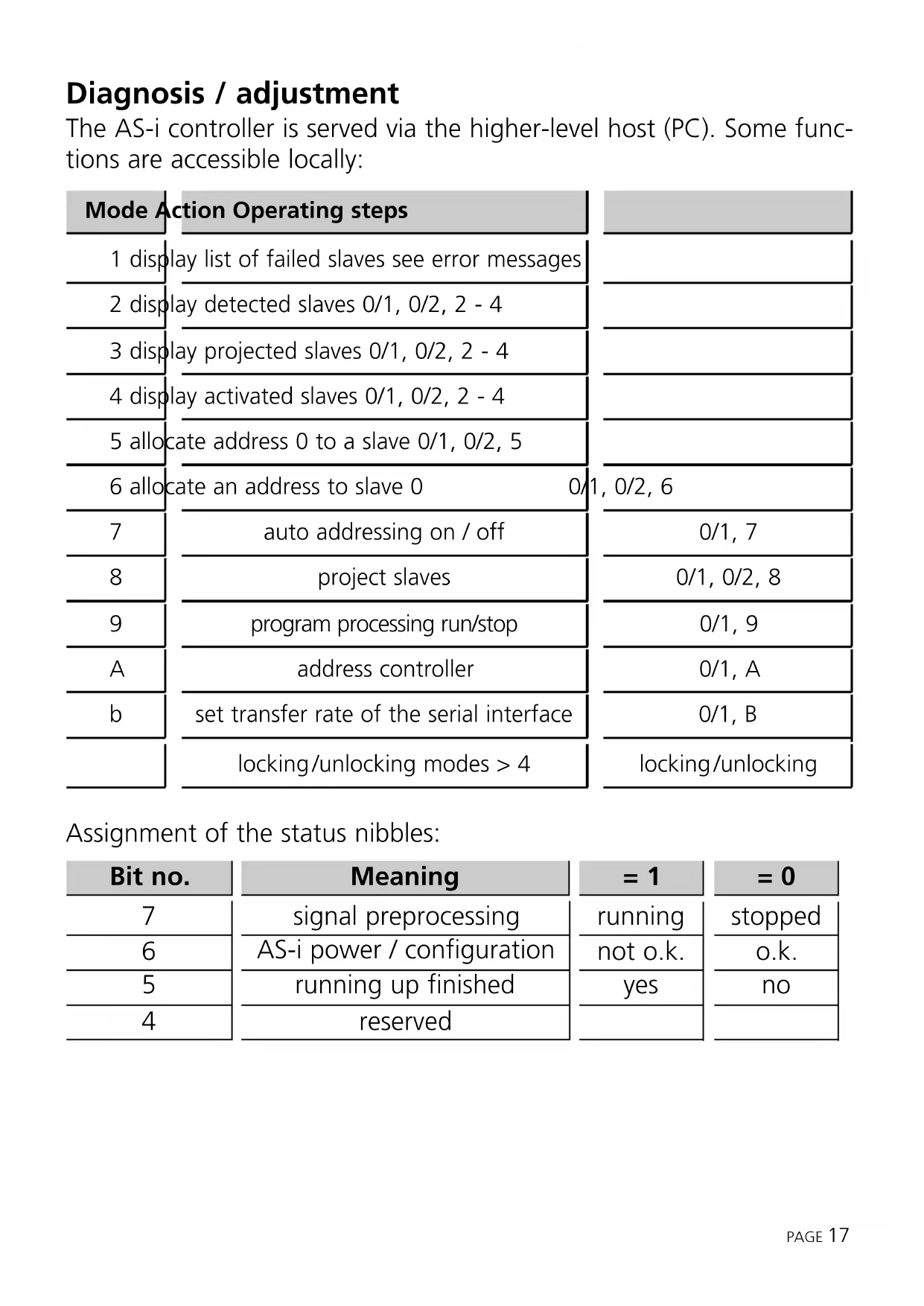
Diagnosis / adjustment
The AS-i controller is served via the higher-level host (PC). Some functions are accessible locally:
| Mode | Action Operating steps | |
| 1 | display list of failed slaves see error messages | |
| 2 | display detected slaves 0/1, 0/2, 2 - 4 | |
| 3 | display projected slaves 0/1, 0/2, 2 - 4 | |
| 4 | display activated slaves 0/1, 0/2, 2 - 4 | |
| 5 | allocate address 0 to a slave 0/1, 0/2, 5 | |
| 6 | allocate an address to slave 0 0/1, 0/2, 6 | |
| 7 | auto addressing on / off | 0/1, 7 |
| 8 | project slaves | 0/1, 0/2, 8 |
| 9 | program processing run/stop | 0/1, 9 |
| A | address controller | 0/1, A |
| b | set transfer rate of the serial interface | 0/1, B |
| locking/unlocking modes > 4 | locking/unlocking |
Assignment of the status nibbles:
| Bit no. | Meaning | = 1 | = 0 |
| 7 | signal preprocessing | running | stopped |
| 6 | AS-i power / configuration | not o.k. | o.k. |
| 5 | running up finished | yes | no |
| 4 | reserved |
0/1 Select mode
| 1 | [288Y]Mode SetPress several times until requested mode is displayed | 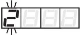 Mode display flashing Mode display flashing | |
| 2 | Mode SetAcknowledgment of the requested mode | Display of the selected mode, display master 1 flashing |
0/2 Select master:
| 1 | [SYDT]Mioae SetAcknowledgment of master 1 | → | 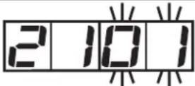 Display master 1,display of 1st slave flashing Display master 1,display of 1st slave flashing |
or:
| 1 |  Mode SetPress once Mode SetPress once |  | 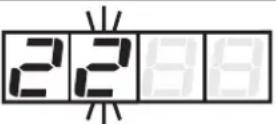 Display of master 2 flashing Display of master 2 flashing |
| 2 |   iviode SetAcknowledgment of master 2 iviode SetAcknowledgment of master 2 | → |  Display master 2,display of 1st slave flashing Display master 2,display of 1st slave flashing |
2/4 Display of identified, projected and activated slaves
| 1 | Select |  de and de and  master (operating steps 0/1 and 0/2) master (operating steps 0/1 and 0/2) |  Display master 1, display of 1st slave Display master 1, display of 1st slave |
| 2 |  Mode SetPress several times Mode SetPress several times |  Display of other slaves Display of other slaves |
5 Allocate address 0 to a slave
| 1 | Select mode and master (operating steps 0/1 and 0/2) | 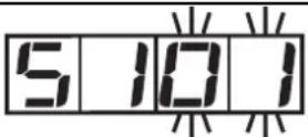 Display master, display of 1st slave flashing Display master, display of 1st slave flashing | |
| 2 | Mode SetPress several times until requested slave is displayed | 5 107Display of slave flashing (here slave 7) | |
| 3 | Mode SetPress once (= acknowledgment) | 5 107Address 0 is stored for selected slave |

Automatic addressing must be switched off (mode 7).
6 Allocate an address to slave 0
| 1 | Select mode and master (operating steps 0/1 and 0/2) | 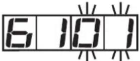 Display master,first free slave address flashing Display master,first free slave address flashing | |
| 2 | Mode SetPress several times until requested address is displayed | 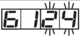 Display of selected address flashing (here address 24) Display of selected address flashing (here address 24) | |
| 3 | Mode SetPress once (= acknowledgment) | New address for slave 0 is stored |
7 Auto addressing on/off
= automatic addressing OFF

= simple automatic addressing ON (1 slave can be addressed automatically)

= multiple automatic addressing ON (several slaves can be addressed automatically)
| 1 | Select mode (operating step 0/1) |  Display of preset value flashing Display of preset value flashing | |
| 2 | Mode SetPress several times until requested setting is displayed | 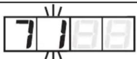 Display of newly selected setting flashing (here 1) Display of newly selected setting flashing (here 1) | |
| 3 | Mode SetPress once (= acknowledgment) | New setting is stored |
8 Project slaves
| 1 | Select mode and master (operating steps 0/1 and 0/2) | 81PPDisplay master, display project mode flashing | |
| 2 | Mode SetPress once (= acknowledgment) | 81PPNew configuration is stored |
9 Program processing run/stop

= program processing running (RUN mode) (LED "CTRL" = on)

= program processing stopped (STOP mode) (LED "CTRL" = off)
| 1 | Select mode(operating step 0/1) | 9C-1Display of modeand preset value |
| 2 | Mode SetPress until requested setting is displayed | 91C-5Display of newly selected setting (here STOP) |
| 3 | Mode SetPress once(= acknowledgment) | 91C - 5New setting is stored |
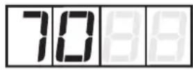
A Address controller (default address = 001)
| 1 | Select mode(operating step 0/1) | [IMAGE]Display of presetaddress flashing |
| 2 | Mode SetPress several times untilrequested address is displayed | 4004Display of new address flashing(here 004) |
| 3 | Mode SetPress once(= acknowledgment) | 8004New address is stored |
The address is only valid for the RS232 interface.
b Set transfer rate of the serial interface
| 1 | Select mode(operating step 0/1) |  Display of preset value flashing Display of preset value flashing | |
| 2 | Mode SetPress several times until requested setting is displayed | Display of newly selected setting flashing (here 96) | |
| 3 | Mode SetPress once (= acknowledgment) | New setting is stored |
Possible settings:b_48 (= 4800 baud), b_96 (= 9600 baud), b192 (= 19200 baud = default), b384 (=38400 baud), b576 (= 57600 baud), b624 (= 62400 baud).
Locking/unlocking modes > 4
| 1 | Select mode (operating step 0/1) | 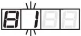 Display of the selected mode Display of the selected mode | |
| 2 | Mode SetPress twice | 8777Display of locking flashing | |
| 3 | Mode SetPress once (= acknowledgment) | 8777Display locking active |
Unlocking: Press both buttons for approx. 5s; as acknowledgment digit 1 is flashing in the LED display.
Error messages

Display of missing/defective slaves
(digit 2 = master; digits 3 and 4 = slave no.); the slaves are displayed at intervals of seconds.
The list of failed slaves can be stored until the slaves have been replaced.
- Press the SET button twice (for the list of master 1) or SET -MODE - SET (for the list of master 2). The lowest address of the error list is displayed flashing.
- Replace the failed slave by a slave with the same configuration and with the address 0; it will receive the indicated address; (the function “multiple automatic addressing” must be activated). If other addresses are displayed, proceed in the same way until the list has been completed.
- The function will be ended when the slaves have been replaced or the SET button has been pressed.

Bus error or timeout at field bus interface

Software version AS-i string 1 ≠AS-i string 2

error during initialisation of the Profibus interface module

AS-i master 2: operating mode already active

AS-i master 2: addressing mode already active

AS-i master 2: error during the setting of the new address

AS-i master 2: error during the deletion of the old address

AS-i master 2: slave with old address does not exist

AS-i master 2: slave with new address exists

AS-i master 2 offline/slave 0 exists
 | AS-i master 2 not in the projecting mode |
 | AS-i master 2 not in the projecting mode |
 | AS-i master 2 not in the projecting mode/ configuration data not valid |
 | AS-i master 2 not in the projecting mode |
 | AS-i master 2: offline |
 | AS-i master 2: parameter value invalid |
 | AS-i master 1: operating mode already active |
 | AS-i master 1: addressing mode already active |
 | AS-i master 1: error during the setting of the new address |
 | AS-i master 1: error during the deletion of the old address |
 | AS-i master 1: slave with old address does not exist |
 | AS-i master 1: slave with new address exists |
 | AS-i master 1 offline/slave 0 exists |
 | AS-i master 1 not in the projecting mode |
 | AS-i master 1 not in the projecting mode |
 | AS-i master 1 not in the projecting mode/ configuration data not valid |
 | AS-i master 1 not in the projecting mode |
 | AS-i master 1 offline |
| E-59 | AS-i master 1: parameter value invalid |
| E-60 | Master 2 does not exist |
| E-61 | No plc program loaded |
| E-70 | No entry in LDS (list of detected slaves) |
| E-71 | No entry in LPS (list of projected slaves) |
| E-72 | No entry in LAS (list of activated slaves) |
| E-73 | No free slave address available |
| E-82 | Key handling disabled |
| E-83 | Function only possible in the projecting mode |
| E-90 | Slave 0 does not exist |
| E-91 | Target address already allotted |
| E-92 | New address could not be allotted |
| E-93 | Multiple automatic addressing not active |
| E-94 | I/O configuration ≠projected configuration |
| E-95 | Incorrect ID code (does not correspond to projected value) |
| E-96 | Addressing not possible since "automatic addressing" has not been activated |
| E-97 | Addressing not possible, slaves are missing |
| E-98 | Protected operating mode is not active |
| E-99 | Slave 0 already exists |
Controllers with one master (AC1003, AC1007)
Input Rating
24V DC 80mA
Output Rating
± 3V DC
Electrical ratings
Controllers with two masters (AC1004, AC1017)
Input Rating
24V DC 80mA
Output Rating
± 2 × 3V DC
- Functions and features
- Programming interface RS232C
- Programming interface RS485
- Mounting
- Electrical connection
- Operating and display elements
- Diagnosis / adjustment
- Auto addressing on/off
- Project slaves
- Program processing run/stop
- A Address controller (default address = 001)
- Error messages
- Electrical ratings
Brand : IFM
Model : AC1004
Category : Industrial Automation