
AVR11 - Receiver ARCAM - Free user manual and instructions
Find the device manual for free AVR11 ARCAM in PDF.
| Product Type | Multi-channel Audio/Video Receiver |
| Brand | Arcam |
| Model | AVR11 |
| Dimensions (W x D x H) | 433 x 425 x 121 mm |
| Net weight | 16.5 kg |
| Gross weight (packaged) | 19.6 kg |
| Power supply | 110-120 V or 220-240 V, 50-60 Hz |
| Maximum consumption | 1.5 kW |
| Standby power consumption | < 0.5 W |
| Output power (7 channels, 8 Ω) | 80 W per channel (70 Hz-20 kHz, <0.02% THD) |
| Output power (7 channels, 4 Ω) | 100 W per channel (70 Hz-20 kHz, <0.02% THD) |
| Signal-to-noise ratio (direct stereo) | 110 dB |
| Frequency response | 20 Hz - 20 kHz ± 0.2 dB |
| HDMI inputs | 7 (HDCP 2.3, 40 Gb/s) |
| HDMI outputs | 2 (including one for Zone 2) |
| Supported audio formats | Dolby Atmos, DTS:X, Auro-3D, Dolby TrueHD, DTS-HD Master Audio |
| Network connectivity | Ethernet, Wi-Fi, Bluetooth |
| Audio streaming | AirPlay 2, Chromecast, Spotify Connect, UPnP, Internet radio |
| Built-in radio | DAB+/FM |
| Acoustic calibration | Dirac Live (microphone included) |
| Maintenance and cleaning | Dust with a dry soft cloth. Do not use chemical or abrasive products. |
| Safety | Do not expose to moisture. Ensure adequate ventilation. Do not place objects on the device. |
| Spare parts and repairability | 5-year warranty (excluding drives). Repairs by an authorized Arcam dealer. |
| General information | High-end HDA receiver. Programmable universal remote control. Firmware update via USB or network. |
Frequently Asked Questions - AVR11 ARCAM
User questions about AVR11 ARCAM
0 question about this device. Answer the ones you know or ask your own.
Ask a new question about this device
Download the instructions for your Receiver in PDF format for free! Find your manual AVR11 - ARCAM and take your electronic device back in hand. On this page are published all the documents necessary for the use of your device. AVR11 by ARCAM.
USER MANUAL AVR11 ARCAM
AV41/AVR31/AVR21/AVR11
HANDBOOK
MANUEL
HANDBUCH
HANDLEIDING
MANUAL
PYKOBODCTBO
MANUALE
手册
朝三殿
EN
HANDBOOK
ARCAM HDA
AV41/AVR31/AVR21/AVR11
Safety Guidelines
Important Safety Instructions
- Read these instructions.
- Keep these instructions.
- Heed all warnings.
- Follow all instructions
- Do not use this apparatus near water.
- Clean only with dry cloth
- Do not block any ventilation openings. Install in accordance with the manufacturer's instructions.
- Don't installearany heatsourcessuchasradiators; heat registers, stoves, or other apparatus (including amplifiers) that produce heat.
- Donot overeat the safety purpose of the polarized or grounding-type plug.
A polarized plug has two blades with one wider than the other. A grounding type plug has two blades and a third grounding plug. The wide blade or the third plug are provided for your safety. If the provided plug does not fit into your outlet, consult an electrician for replacement of the obsolete outlet.
- Protect the power cord from being walked on or pinched, particularly at plugs, convenience receptacles, and the point where they exit from the apparatus.
- Only use attachments/accessories specified by the manufacturer.
- Use only with the cart, stand tripod brackets, or table specified by the manufacturer, or sold with the apparatus.
When a cart is used, use caution when moving the cart/apparatus combination to avoid injury from hip over.

-
Unilignithparasudiralinglighntingstomsswhen unused for long periods of time.
-
Refer all servicing to qualified service personnel. Servicing is required when the apparatus has been damaged in any way, such as power supply cord or plug is damaged, liquid has been spilled or objects have fallen into the apparatus, the apparatus has been exposed to rain or moisture, does not operate normally, or has been dropped.
-
Object or liquid entry
WARNING - Take care that objects do not fall and liquids are not spilled into the enclosure through any openings. The equipment shall not be exposed to dripping or splashing. Liquid-filled objects such as vases should not be placed on the equipment.
- Climate
The equipment has been designed for use in moderate climatics and in domestic situations.
- Cleaning
Unplug the unit from the mains supply before cleaning.
The case should normally only require a wipe with a soft, lint-free cloth. Do not use chemical solvents for cleaning.
We do not advise the use of furniture cleaning sprays or polishes as they can cause permanent white marks.
- Power sources
Only connect the equipment to a power supply of the type described in the operating instructions or as marked on the equipment.
The primary method of isolating the equipment from the mains supply is to remove the mains plug. The equipment must be installed in a manner that makes disconnection possible.
- Abnormal smell
If an abnormal smell or smoke is directed from the equipment, turn the power off immediately and unplug the equipment from the wall out of Contact your dealer and do not reconnect the equipment.
- Damage requiring service
The equipment should be serviced by qualified service personnel when:
A: The power-supply core or the plug has been damaged, or
8. Objects have fallen, or liquid has spilled into the equipment, or
C The equipment has been exposed to rain, or
12. the equipment does not appear to operate normally or exhibits a marked change in performance or
The equipment has been dropped or the endosure damaged.


CAUTION: To reduce the risk of electric shocks, do not remove cover (or back). No user serviceable parts inside. Refer servicing to qualified service personnel.
WARNING: To reduce the risk of fire or electric shock, do not express this appellation to rain or moisture.
The lightning flash with an arrowhead symbol within an equilateral triangle, is intended to alert the user to the presence of unsatisfied dangerous voltage within the product's enclosure that may be of sufficient magnitude so constitute a risk of electric shock to persons.
The explanation point within an equilateral triangle is intended to alert the user so the presence of important operating and maintenance (servicing) instructions in the literature accompanying the product.
CAUTION: In Canada and the USA, to prevent electric shock, match the wide blade of the plug to the wide slot in the socket and insert the plug fully into the socket.
Class II product
This equipment is a Class II or double insulated electrical appliance. It has been designed in such a way that it does not require a safety connection to electrical cards ("ground" in the U.S).
Warning
Mains plug/appliance coupler is used to disconnect device and it's stall remains readily operable.
Safety Compliance
This equipment has been designed to meet the IEC/HN 6006s International electrical safety standard.
This device complies with Part 15 of the FCC Rules. Operation is subject to the following two conditions:
This device may not cause harmful interference, and
This device must accept any interference received, including interference that may cause undesired operation.
The building installation shall be regarded as providing protection in accordance with the rating of the wall stocke outlet.
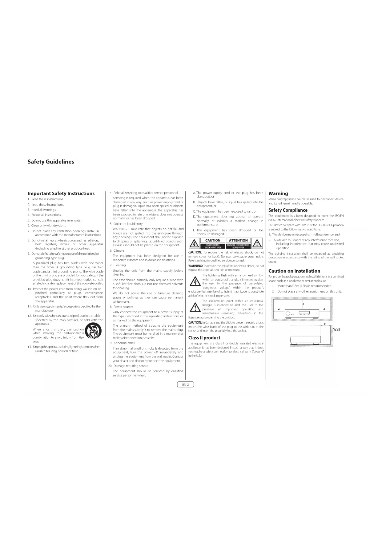
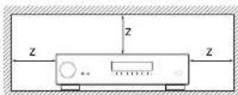
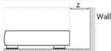
Caution on installation
For proper heat dissipation, do not install this unit in a confined space, such as a boxkake or similar enclosure.
More than 0.3m (12in) is recommended.
Do not place any other equipment on this unit.
FCC Information (for US customers) PRODUCT
CONTAINS TRANSMITTER MODULE FCC ID: APILUXASTRO1, APILUXABT01
This product complies with Part 15 of the FCC Rules. Operation is subject to the following two conditions: (1) this product may not cause harmful interference, and (2) this product must accept any Interference received, including interference that may cause undesired operation.
IMPORTANT NOTICE: DO NOT MODIFY THIS PRODUCT!
This product, when supplied as indicated in the instructions contained in this manual, meets FCC requirements. Modification not expressly approved by ARCAIA may void your authority, granted by the FCC, to use the product. CAUTION (or Bluttooh/We/He)
To comply with FCC RF exposure compliance requirement, separation distance of at least 20~cm must be maintained between this product and all persons.
This product and its antenna must not be co-located or operating in conjunction with any other antenna or transmitter.
NOTE
This product has been tested and found to comply with the limits for a Class B digital device, pursuant to Part 15 of the FCC rules. These limits are designed to provide reasonable protection against harmful interference in a residential installation.
This product generates, uses and can radiate radio frequency energy and, if no, installed and used in accordance with the instructions, may cause harmful interference to radio communications. However, there is no guarantee that interference will not occur in a particular installation. If this product does cause harmful interference to radio or television reception which can be determined by turning the product OFF and ON, the user is encouraged to try to correct the interference by one or more of the following measures:
Reorient or relocate the receiving antenna.
L Increase the separation between the equipment adi:canadians:CANICES-3(B)/NMB-3(B) "for the receiver. indoor use only"
C. Connects the product into a bullet on a circle different form that, at which the receiver is connected.
Consult the local retailer authorised to distribute this type of product or an experienced radio / TV technician for help.
IC Information (For Canadian customers)
PRODUCT
CONTAINS TRANSMITTER MODULE IC:
6132A-LUXASTRO1,6132A-LUXABT01
This product complies with RSS-247 of Industry Canada. Operation is subject to the following two conditions: (1) this product may not cause harmful interference, and (2) this product must accept any interference received, including interference that may cause undesired operation. This Class B digital apparatus complies with Canadian ICES 003.
CAUTION
To reduce potential radio interference to other users, the antenna type and its gain should be so chosen that the equivalent isotropically radiated power (eIRP) is not more than that permitted for successful communication. (1) the device for operation in the band 5,150-5,250 MHz is only for indoor use to reduce the potential for harmful interference to co-channel mobile satellite systems. (2) high-power radars are allocated as primary users (i.e., priority users) of the bands 5,250 - 5,350 MHz and 5,650 - 5,850 MHz and that these radars could cause interference and/or damage to LE-LAN devices.
For Canadian customers / Pour les clients
canadiens:CANICES-3B/NMB-3B"for
indoor use only
ATTENTION
RF Exposure Information
This equipment complies with FCC/TC radiation exposure limits set forth for an uncontrolled environment and means the FCC radio frequency (RF) exposure guidelines in Supplement C. In QF-165 and HSS-102 of the TC radio frequency (RF) Exposure rules. This equipment has very low levels of RF energy that are deemed to comply without testing of specific absorption ratio (SAR).
Safety Information (for European customers)
Avoid high temperatures. Allow for sufficient heat dispersion when installed in a rack.
Handle the power cord carefully. Hold the plug when unplugging this cord.
Keep the unit free from moisture, water, and dust.
Unpug the power cord when not using the unit for long periods of time.
Do not obstruct the ventilation holes.
Do not let foreign objects into the unit.
Do not let insecticides, benzene, and thinner come in contact with the unit.
Never disassemble or modify the unit in any way.
Ventilation should not be imaged
Ventilation openings with items, such as newspapers, tablecloths or curtains.
Naked flame sources such as lighted canister should not be placed on the unit.
Safety Information (for European customers)
Observe and follow local regulations regarding battery disposal.
Do not expose the unit to dropping or splashing fluids.
Do not place objects filled with liquids, such as vases, on the unit.
Do not handle the mains cord with wet hands. When the switch is in the OT position, the equipment is not completely switched off from MAIRS.
The equipment shall be installed near the power supply so that the power supply is easily accessible.
A note about recycling
This product's packaging materials are recyclable and can be reused. Please dispose of any materials in accordance with the local recycling regulations. When discarding the unit, comply with local rules or regulations.
Batteries should never be thrown away or incinerated but disposed of in accordance with the local regulations concerning battery disposal.
This product and its supplied accessories, excluding the batteries, constitute the applicable product according to the WEEE directive.
Correct disposal of this product
These markings indicate that this product should not be disposed with other household waste throughout the EU.


Pb
To prevent possible harm to the environment or human health from uncontrolled waste disposal and to material resources, this product must be disposed of responsibly.
In dispase of your product, please use your oral return and collection systems or comate. the inall where the product was purchased.
Radio specificton (for Europe model)
| Time Frequency Range Max. RF Power |
| Bluetooth 2.402-2.480MHz 70dBm |
| wAN AN 2.451-2.460,6.798,5.98kHz 70dBm |
| 5GHz Radio 5.150-5.250MHz 236dBm |
| 5.250-5.350MHz 236dBm |
| 5.470-5.850MHz 400dBm |
| Note: The above specifications are based on the RE directive |
| There is a possibility if can vary by country. |
Welcome
Thank you and congratulations...
for purchasing your Arcam HDA Receiver.
Arcam has been producing specialist audio products of remarkable quality for over three decades and the new Receivers are the latest in a long line of award winning Hi-Fi. The design of the HD4 range draws upon all of Arcam's experience as one of the UKs most retooled audio companies, to produce Arcam's best performing range of products yet designed and built to give you years of viewing and listening enjoyment.
This handi book is intended to give you a detailed guide to using the Receiver. It starts by giving advice on installation, moves on to describe how to use the product and finishes with additional information on the more advanced features. Use the contents list shown on this page to guide you to the section of interest.
We hope that your HDA receiver will give you years of trouble-free operation. In the unlikely event of any fault, or if you simply require further information about Arcam products, our network of dealers will be happy to help you. Further information can also be found on the Arcam website at www.arcam.co.uk.
The HDA development team
Contents
Safety Guidelines EN-2
Welcome
Before You Begin... EN-6
Trademark Acknowledgments EN-8
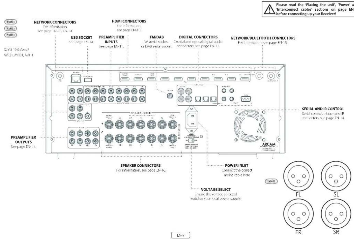
Rear Panel Connections and Controls EN-9
Audio/Video Connections EN-10
Connection Guide EN-12
Radio & Wireless Audio Connectors EN-13
Other Connectors EN-14
Speakers
Connecting Speakers EN-16
Operation
Extended front panel menu EN-18
Updating firmware via USB EN-18
Front Panel Operation EN-19
Remote Control EN-20
Customising the Remote
Essential Setup
Auto Speaker Setup
Setup Menus
Connecting to a Network
EN-4
EN-15
EN-17
EN-22
EN-28
EN-29
EN-30
EN-34
Decoding Modes EN-35
Tuner Operation EN-37
Troubleshooting EN-38
Specifications EN-40
Worldwide Guarantee EN-42
Professional Installation?
It may be that the Receiver has been installed and set up as part of your Hi-Fi installation by a qualified Arcam dealer. In this case, you may wish to skip the sections of this handbook dealing with installation and setting up, and move directly to the sections dealing with using the unit. Use .no Canteen list to guide you to these sections.
DIY setup?
The Receiver is a powerful and sophisticated piece of AV equipment. If you are setting the unit up yourself, it is recommendant that you read this handbook thoroughly before beginning. For instance, correct speaker configuration and placement is a key to getting the most out of your Receiver and making sure that all the elements of your system work in harmony.
Before You Begin...
Arcam HDA Receiver
The Receivers are high-quality and high-performance home-cinema processors and amplifiers built to Arcam's quality design and manufacturing standards. They combine digital processing with high-performance audio and video components, cobring you an unrivalled home entertainment studio.
The Receiver allows switching and control of seven analogues and six digital audio sources in addition to internal FM and DAB+ radio - as well as networked audio sources - making any of the models an ideal hub for both home-cinema and two-channel stereo systems.
Since many of these source components are also capable of generating video signals, the Receiver includes broadcast-quality switching for DMI (xHDMI2.1) and 40Cot/s-HCP2.3), video/audio signals. Control of the Receiver is either by front panel control buttons, R remusate control, IP (Ethernet) control or RS232 port.
The remote control supplied with: The Receiver is a multidevice 'universal' learning remote control which is simple to use, and once set up it is able to control a complete system. It can be programmed using its vast internal code library to control CD and BD players, PVRs, TVs and other devices.
The installation of the Receiver in a listening room is an important process which requires care at every stage. For this reason, the installation information is very comprehensive and should be followed carefully to achieve an unvalued level of performance.
The Receiver is designed to produce a level of performance that will truly bring music and movies to life.
Placing the unit
Place the unit on a level, firm surface, avoid rigidity, sunlight and sources of heat or damp.
Do not place the Receiver on top of a power amplifier or another source of heat.
Do not place the amplifier in an enclosed space such as a bookcase or closed cabinet unless there is good proviso on for ventilation (see page EN-2).The Receiver will run warm during normal operation.
1 Do not place any other component on it. In the amplifier as this may obstruct airflow around the heat sink, causing the amplifier to run hot. (The unit, placed on top of the amplifier would become hot, too.)
Make sure the remote-control receiver on the front panel display is unobstructed, otherwise this will impair the use of the remote control. If line of sight is impractical, a remote-control repeater can be used with the rear panel connector (see page EN-34).
Do not place your record deck on top of a unit. Record decks are very sensitive to the noise generated by mains power supplies which will be heard as a background 'hum' if the record deck is too close.
Power
It be amplifier is supplied with a moulded mains plug already fitted in the lead. Check that the plug supplied fits your supply - should you require a new mains lead please contact you Arcam dealer
If your main supply voltage or main plug is 105 mm, please contact your Aram dealer immediately.
The Receiver can be switched for operation between 220-240V (switch position 230V) and 110-120V (switch position 115V).
NOTE: Ensure that the Receiver is switched off and the power lead removed before changing the position of the voltage range switch.
Push the Hc plug end of the power cable into the socket on the back of the amplifier, making sure that it is pushed in firmly. Plug the other end of the cable into your main socket and, if necessary, switch the socket on.
The Receiver can be turned on using the power switch on the front panel. White switched on, the front panel HD will glow white.
Standby power
The Receiver can be switched into standby mode using the ch button on the remote control. While in standby mode the front panel LED will glow red and (with default settings) power consumption is less than 0.5 Watts.
While in Stanoy mode, it may be possible to hear a slight residual hum coming from the mains transformer inside the amplifier. This is perfectly normal. However, if the unit is to be left unused for an extended period, we recommend that you disconnect it from the mains supply to save power.
Interconnect cables
We recommend the use of high-quality screened cables that are designed for the particular application. Other cables will have different impedance characteristics that will degrade the performance of your system (for example, do not use cable intended for video use to carry audio signals). All cables should be kept as short as is practically possible.
It is good practice when connecting your equipment to make sure that the mains power-supplying cabinet is kept as far away as possible from your audio cables. Failure to do so may result in unwanted noise in the audio signals.
For information on speaker cables, please refer to the 'Speakers' section, beginning on page EN 16.
Radio interference
The Receiver is an audio device containing microprocessors and other digital electronics. Each model has been designed to vary high standards of electromagnetic compatibility.
This is a Class A product. In a domestic environment this product may cause radio interference, in which case the user may be required to take adequate measures.
If the Receiver causes interference to radio or television reception (which can be determined by switching the Receiver off and on), the following measures should be taken:
Reorient the receiving antenna or route the antenna cable of the affected device as far as possible from the ARCAM Receiver and its cabling.
Relocate the affected device with respect to the ARCAM Receiver.
11. Connect the affected device and the Receiver to different main outlets.
If the problem persists, please contact your Arcam dealer.
Trademark Acknowledgments

CNDyBn
Dolby Vision, Dolby Atmos, Dolby Audio
Myriolinated centre (Tome) from Dolly Bablajacica, Dolly, Talay Voini, Dolly Atrora, Dolly Aitka, and the double-D symbol are represent numerals of Dolly Bablajacica.

DTS:X
For DPs patents, see http://patentsdb.com/Manualize/under license from DTS (Elsevier Inc), DTS, the symbol, DTS, in corollary icon with the symbol. DLSX and the DLSX logo are represented as trademarks or trademarks of DLS, Inc. in the United States and/or other countries. In DTS, Inc. All Rights Reserved.

DTS Virtual: X^*
For D5 patents see http://polarindustries. Manufacturing License/ licenses from D5 Licensing Limited, D5, the symbol, D5 and the symbol together, Viralk Inc.; the D5 Viralk logo are registered trademarks and/or trademarks of D5, Inc., in the United States and/or other countries © D5, Inc. All rights reserved.
IMAX ENHANCED
IMAX\* & DTS\*
Manufactured under license, from IIAX Corporation. MAX® is a registered trademark of IIAX Corporation in the United States and/or other countries. For STS patents, see http://patents.tds.com. Manufactured under license from DTS unclustering DTS; the Symbol DS and the symbol together are registered trademarks or trace marks of STS; nc in the United States and/or other countries. In DTS, Inc. All Rights Reserved.
ALRO
Auro-3D
Manufactured under license from Auto Technologies, Auto, Auto 3D, Auto Codex and AutoMatic are registered Trademarks of Auto Technologies.

AAC/AAC Plus
apples s a modern of Coding Technologies See http://codetech.whoist.novir.net for more information:
HOMI
17GM, the BMW AG and Hefei Delin MultiMedia Interactive interfaces are registered trademarks of BMW Licensing LLC.
Bluetooth The Bluetooth® word mark and logos are registered trademarks owned by the Bluetooth SIG, Inc. and any use of such marks is prohibited internationally. Industries, Incorporated S, under license. Other trademarks and trade names are those of their respective owners.
Quentinum aqutCD. Quentinum is a landmark of Quentinum incorporated registered in the United States and other countries, which is a trademark of Quentinum Togethersoft GmbH, Germany, registered in the United States and other countries.
Apple, AirPlay and the AirPlay logo, ifred, Phone and iPad are trademarks of Apple Inc. registered in the U.S.and other countries.Apple is a trademark of Apple Inc.
AirPlay 2 works with iPhone, iPad, and iPod touch with iOS 1.1 or later; Mac with iOS X Mountain Lion or faster, and iOS with iOS 10.2.2 or later.
WiFi The Wi-Fi Alliance
Google, Google Play, Computer and other related markets are trademarks of Google LLC. The Google Assistant requires an internet connection and is not available in certain countries and languages. Availability and receipt of certain libraries and services are devices, services, and network dependent and may not be available in all areas. Controlling for a smart device in your home requires compatible smart devices. Subscriptions for services and applications may be required and additional fees can occur.
vtTuner this product is protected by certain intellectual property rights of Nukis and Sridgeco. Use or distribution of such technology outside of this product is prohibited without a license from Nukis and Sridgeco or an authorised subsidy.
MP3 WPEG1age-tauening,phosphoriedfornearthoehlls and human mufiness.
The quality issues is subject to third party licenses found at: http://www.copyright.com/copy/3rd-party-issues/
FLAC
11AC Decader Copyright 7/2000, 3/2011, 7/2009, 2004, 2005, 2007, 2008, Cohn Coation
Redistribution and use in source and binary forms, with or without modification, are permitted provided that the following conditions are met:
Reditistors of source code must ran the above copyright notice, this list of conditions and the following disclaimer
Redistributions a binary form must reproduce the above copyright notice, this list of conditions and the following disclaimer in the documentation and/or other materials provided with the distribution:
Neither the name of the Xiphos Foundation nor the names of its contributors may be used to endorse or promote products derived from this software without specific prior written permission.
THIS SHEAR IS FREDDIED BY THE COFFEE OF THE COILS AND CONTINUINGLY AS I AND ANY EXPRESS OR UNLESSWARD WARRANTYINGS, INCLUDING BUT NOT LESS THAN 100% WILL BE ISSUED. THE COILS ARE NOT REPRESENTED IN ANY NUMBERS. THE COILS ARE NOT REPRESENTED IN ANY NUMBERS.

MQA
BIA Baster Quality Author cated
MIGA is an award-winning British technology that delivers the sound of the original master recording. The master MIGA file is fully authenticated and is small enough to be downloaded. Visit www.miga.com for more information.
Aram A. Arora, Institute of MCA technology, which enables you to play back MCA audio files and learn, delivering the awarded original music recording.
"MOO on MOO Study indicates that the composer is innovating and playing on MOO content in her, and does not compromise to ensure that the sound is critical to that of the source material. MOO Study indicates it is playing an MOO Study role, which has either been approved in the music by the artist/ producer or has been verified by the copyright owner.
b/CA and the Sound Wave Service are registered
Audio/Video Connections
Before connecting your Receiver to your source components and speakers, please read through the next few pages which will explain all the instal and output, connectivity that is available. The 'Speakers' section explains how to connect up your speakers to avoid carriage to the amplifier and how to arrange your speakers for best performance.
General
The inputs are named to make it easier to reference connected devices (e.g. BID) [18] [19] they all have the same input circuit, so there is no reason why you should not connect a different device to any of the inputs. For example, if you had two BD players and the AV input was not being used, then the second BD player could be connected to the AV input.
When connecting a video source, its audio must be connected to the corresponding sociels. For example, if you had a satellite decoder plugged into a Sardio input, the audio must be connected to the Sardio inputs!
Making Connections
take care to place cables as far from any power supply cooling as is practicable, to reduce hum and other noise problems.
NOTE: For each input, you must set the 'Video Source' and 'Audio Source' settings according to the connection type. (see 'Input Config.' on page EN-31)

HDMI Connectors
PVR, UHD, BD, SAT, AV, GAME, STB
Connect the HDVI video outputs of your source equipment to these corresponding HDVI inputs.
OUTPUT (Zone2-AVR21, AVR31, AV41)
Connect this output to the IDM video input of your display device. Output is compatible with HDMI Enhanced Audio Return Channel (eARC). If you have a supported television then sound from the television's internal tuner (e.g. Freeview, Freesat, DVB T) will be available using the Receiver's Display input.
Digital audio connectors
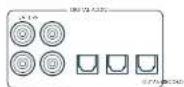
SAT, PVR, BD, CD, STB, AV
Connect these inputs to the digital outputs of your available source equipment.
Zone 2 connectors (AVR21, AVR31, AV41)
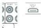
The Z22 out HDMI connector can be used to connect the output of the receiver to a system located in a second room.
Analogue preamplifier outputs
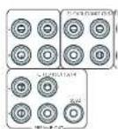
All preamplifier analogue outputs are buffered, have a low output impedance, are at line level and follow the Zone 1 volume control setting, they are able to drive long cables or several inputs in parallel if required.
For more information on connecting speakers or additional power amplifiers, see pages FN-9 and FN-16.
The AVM1 has X-R output, in addition to the pheno pre-cuts for connection to an external amplifier.
Analogue audio inputs
STB, GAME, AV, BD, PVR, CD
Connect the left unit right inputs to the left and right outputs of your source equipment.
Front panel AUX input

The front panel AUX input can be used as an analogue input, using a stereo 3.5mm lead.
Front panel PHONES socket
This socket accepts headphones with an impedance rating between 32 and 500 fitted with a 1.5mm stereo jack plug. The headphone socket is always active, except when receiver is muted.
When the handheld jack is immersed, the snubber outputs and analogic presamplifier outputs are automatically mixed.
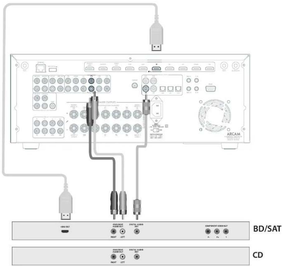
Connection Guide
Blu-ray Disc (BD)/DVD player
IIC diagram shows how to make audio and video connections from a typical BTD/ATD player.
Whether HDV, digital or analogue connections are used, connecting using the input/inputs labeled on the Receiver-wild operation.
Satellite receiver
A satellite receiver is connected with the same order of preference according to the outwards provided by the satellite receiver.
CD player
Connect the digital output in the digital cd input of the Receiver and analogue output to the analogue cd in out of the Receiver, using a high quality interconnect cable.
NOTE: For each input, you must set the 'Audio Source' setting according to the connection type. (see "Input Config." on page EN-31)
Radio & Wireless Audio Connectors

DAB/FM Connector
The Receiver is fitted with an FM and a DAB/DAB1 receiver module. The type of aerial you need depends on your listening preferences and the local conditions.
Your Receiver is capable of superb radio reception, but only if it is receiving a good quality transmission signal.
Try the aerials supplied with your unit. If you are in a medium to strong signal area, these should be adequate for good reception. In areas with poor signal strength, you may require a roof or loft mounted aerial.
Contact your local Arcam dealer or aerial installation experts for advice about local reception conditions.
In strong signal areas, the DAB/FM/Fuvec aerial supplied can be used with reasonable results. Mount the aerial as high up as possible on a wall.
In the UK the "elements need to be positioned vertically for DAB reception since broadcasts are vertically polarised. In other localities, check with your Arcan dealer or try both horizons and vertical positions for best reception.
Try each usable wall of the room to see which gives best reception and use tacks or adhesive tape to secure the aerial in a 'T shape, but note that, no tacks should come into contact with the internal wire of the aerial.
When installed and receiving DAB/TM, check the signal strength by pressing the front panel or remote control's INFO button until the signal quality indicator is displayed.
In weak signal areas, a high gain, externally mounted or roof mounted aerial is desirable in order to receive the highest number of services.
In Band II transmission areas (such as the UK), use a multi-criterion, Yap aircraft with the elements mounted vertically, as the transmitters are vertically polarised. If you are close to more than one transmitter, use an omnidirectional or folded dipole serial.
If the DAB services in your area are parameterised in 1-band, then ask your dealer for advice for the best aerial to use.
Wi-Fi/Bluetooth
fusing the Wi-Fi or Bluetooth features of the Receiver, please attach the single antenna for the Bluetooth and the two antennas as for the Wi-Fi.
Other Connectors
Serial connector
RS232 serial connector

The connector is used with control devices having an RS232 serial port (for example, Ciestron and AMX touch-screen controllers).
Network connector
Networking is a large subject and on my the briefest guidelines are presented in this handbook. Please contact your Arcane dealer or socialist installer for more information about introducing the Receiver into your computer network.

Ethernet
If an Ethernet cable is connected, the Receiver will automatically attempt to connect to your network.
You should use CATS cable plugged into the RJ45 socket labelled ETHERNET on the rear panel.
If your network uses static IP addressing rather than DHCP, you will need to provide IP address: gateway and DNS; see page Dh-34 for information on setting up the network.
USB connector
The Receiver can be unicast via the USB socket on the host of the unit, if no network connection and so "Over The Air" update is not available.
Trigger connectors
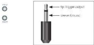
The trigger connectors (TRIG Z1 and TRIG Z2) provide an electrical signal whenever the Receiver is switched on and the relevant zone enabled.
The trigger signal can be used to switch on and off compatible pieces of home entertainment equipment, for example, you could set up a trigger to turn on your television and BD player whenever the Receiver was switched on.
There are two trigger output sockets on the Receiver, each capable of outputting a 12V, 70mA switching signal. The socket is disagreed for mono 35mm jacklet tip in the trigger output, sleeve is ground.
TRIGZ1
Use for remotely turning on and pit power amps or source equipment for Zone 1. On=120; Off=0V.
TRIGZ2(AVR21,AVR31,AV41)
Use for remotely turning on and off power amps or source equipments: for Zorc 9.0n = 12V, Off = 0V.
Infrared (IR) connectors

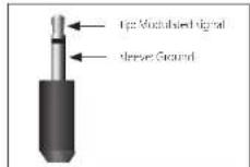
The infrared inputs 21 IR and 22 IR allow the connection of external IR receivers, either when the Receiver front panel IR receiver is fully or partially obstructed or to allow the use of a remote control in zone 2.
There are two IR inputs on the Receiver, each designated for stereo or mono 3.5mm Jacks. Tip is the modulated signal, sleeve is ground.
Z1R
This input is intended for use with a local IR receiver when the front panel of the Receiver is blocked.
Z2 IR (AVR21, AVR31, AV41)
This input is intended for use with an Ili receiver in Zone 2 to allow remote control of Receiver from a second room.
A supplier of infrastructure receivers and emitter accessories and systems Xantech. See www.xantech.com for more information, or ask you to email us.
NOTE: The IR inputs on the Receiver are designed for modulated signals. If the external IR receiver demodulates the IR signal, it will not work. Also the unit does not provide power for external receivers on the IR jack, therefore an external power source will be required.
NOTE: Sockets referring to '22' relate to connections used in multi-room installation. For more information on these connectors, see page EN-1.1.
Speakers
The AVR5/AVR11/AVR21/AVR31/AVR41 allows you to connect up to sixteen speakers. The AVR41 is designed to be used with additional power amplifiers for all channels. The AVR5/ AVR11/AVR21/AVR31 has 7 channels of amplification. 5 channels of amplification correspond to speakers installed in the front left, centre, front right, surround left, surround right. The remaining 2 channels of amplification can be assigned as:
bi-amp the front left and right
surround back left and surround back right
height1 left and right
Zone 2 left and right (AVR21, AVR31, AV41)
Height front left, height front right, height back left, height back right and five more additional speakers can be attached using an additional power amplifier, see page EN-16 for more information.
With the addition of correctly installed and configured height channels, Do by Atmos for the Home, DTSX or Aero 3D brings the ultimate cinema sound experience to your home theatre to create powerful, mixing audio that flows around you.
The configuration and placement of your speakers is very important. All speakers, with the exception of the subwoofer(s), should be arranged around your normal viewing/listening position. The subwoofer should be placed in a position which gives an even frequency response in all listening positions. Incorrect placement leads to bass boom in some areas. Often the only way to find a good position for your subwoofer(s) is by experimentation. A good place to start experimenting is close to a wall but at least 1m away from any corners. You can also consult your subwoofer/handbook for placement suggestions.
Connecting Speakers
To connect each of the speakers, uncrew the corresponding terminals on this back of the Receiver, insert the speaker wires through the hole in each port and screw the terminals back up. Make sure that the red (positive/-) terminal of the speaker is connected to the red (positive/-) terminal on the back panel, and the black (negative/-) terminal of the speaker is connected to the black (negative/-) terminal on the back panel.
It is important that no stray strands of wire from these connections are allowed to touch another cable or the product casing. Failure to ensure this can cause a short circuit and damage your Receiver.
Ensure the unit is switched off whilst connecting speakers. Do not over-tighten the loudspeaker terminals, or use a wrench, pliers, etc., as this could damage the terminals and this would not be covered under the product's warranty.
Speaker cables
The speakers should be connected to the amplifier using good-quality, high-purity, low impedance copper cables. Cheap speaker cables should be avoided - they are a false economy and can significantly degrade the sound quality.
The cable runs to the speakers should be as short as possible. Connections in the speaker terminals should always be finger tight, whether using tape wires or spadecom connectors.
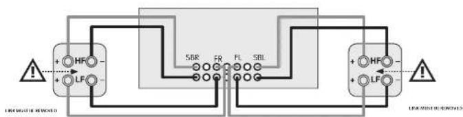
Bi-amping the Front Left & Front Right speakers
Hi amping is the use of two amplifier channels per speaker. Hi amping can provide better sound quality than conventional single wiring. If you do not have Surround Back speakers (i.e., you have a 5" surround system, not a 7" system) then you can use the spare Surround Back speaker outputs to amplify the front left and right speakers if your speakers support hi-mping. The spare channels can alternatively be used to power stereo speakers in another room (Zone 2).
Speakers that support bi-amping have two sets of 1 / 7 terminals per speaker, usually linked together by metal strips. These metal strips MUST be removed when bi-amping; failure to remove them will result in damage to the amplifier that is not covered under warranty.
To iB-amp the front left and right speakers, remove the metal strips from the speaker terminals. Connect the wooder or LF terminals to the FL and FR terminals on the Receiver. Connect the tweeter or HF terminals to the SBL and SBR terminals on the Receiver. Finally, navigate to the Setup Menu 'Spkr Types' and set the Use Channels 6+7 for menu option to iBamp L-R see page EN-32.
Connecting Subwoofer
The Receiver also allows up to four active subwoofoers to be connected to the SUB or Ch13/14/15/16 outwards. Refer to your subwoofer handbook for the correct setting up and connection procedure for your particular subwoofer(s).
[16
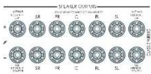
Using external power amplifiers
he internal power amplifier of the Receiver can be supplemented or replaced with external power amplification, such as the Arcam PA720. Connect the PREAMP OUT sockets to your power amplifier inputs:
FL, FR
Connect these to the equivalent Right and Left front channels of your power amplifier.
C
Connect these to the Centre front channel of your power amplifier.
SUB
Subwoofer outputs. Connect this to the input of your active subwoofer(s), if present.
SR, SL
Surround Right and Surround Left outputs. Connect these to the Surround Right and left power amplifier inputs.
SBR, SBL
Surround Back Right and Surround Back Left outputs. Connect these to the Surround Back Right and Surround Back Left power amplifier Inputs.
Height 1 (Height Front), Height 2 (Height Back)
Height Front and Height Back Connects these to the Height channel power amplifier inputs.
All preamplifier analogue outputs are buffered, have a low output impedance and are at line level. They are able to drive long cables or several inputs in parallel if required.
Operation
Operating your Receiver
For information display we recommend you use the OSD (On-Screen Display) on your display device wherever possible.
Switching on
Press the front panel power button in the Power LED will glow white when initialisation is complete, the display shows the volume setting and the name of the selected input.
Please wait until the unit has finished initialising before operating the Receiver. It is recommended that if the unit is switched off, you should wait at least 10 seconds before switching the unit back on.
Standby
The Receiver has a standby mode which can be entered by pressing STANDBY on the remote control. When in standby mode, the display is blank and the POWER cows red.
If the unit is to be left unused for an extended period, we recommend that you disconnect it from the mains supply to save power.
To switch on from standby
Press the STANOGY button on the remote control, any key on the front panel (other than the power button) or rotate the volume knob.
Front panel display
The Receiver is ready for use after about four seconds.
he display window shows the currently selected source and the last selected information view setting (this information line can be changed using theINFO button).
The current volume setting for Zone 1 is displayed on the front panel. The volume setting for Zone 2 is displayed temporarily whenever it is activated.
The front panel display is also used for unit setup after processing the MENTION of the front panel or remote.
Selecting a source
In select a particular source, press the INPUT-INPUT+ buttons until that source is shown on the front panel display, or if available) press the corresponding source button on the remote. The following sources are available:
| STB Set Top Box input |
| GAME Game console input |
| AV Audio/Visual input |
| SAT Sate life input |
| 3D Blurring Disc/DVD player input |
| UHD UHD player input |
| PVR Personal Video Recorder input |
| CD Compact Disc player input |
| FM Internal tuner input |
| DIAR Internal tuner input (this source is market dependent and may not be available on your Receiver) |
| NFI Ethernet input |
| ST BT input |
| AUX Auxiliary (front panel) input |
| DISPLAY The Audio Return Channel (ARC) from a compliant display. Use this with a compliant television using internal TV tuners. |
Most audio inputs have both analogue and digital connections. You must specify the type of connection used for each input using the Audio Source option in the Input Config', menu, see page EN 31. Note that an incorrect setting will result in no sound - the default, for inputs with HDMI is HDMI audio. If you are not using HDMI audio then this setting must be changed. For inputs that do not have HDMI, the default is glial audio.
The processing mode and Stereo Direct functions are remembered and recalled for each Individual input.
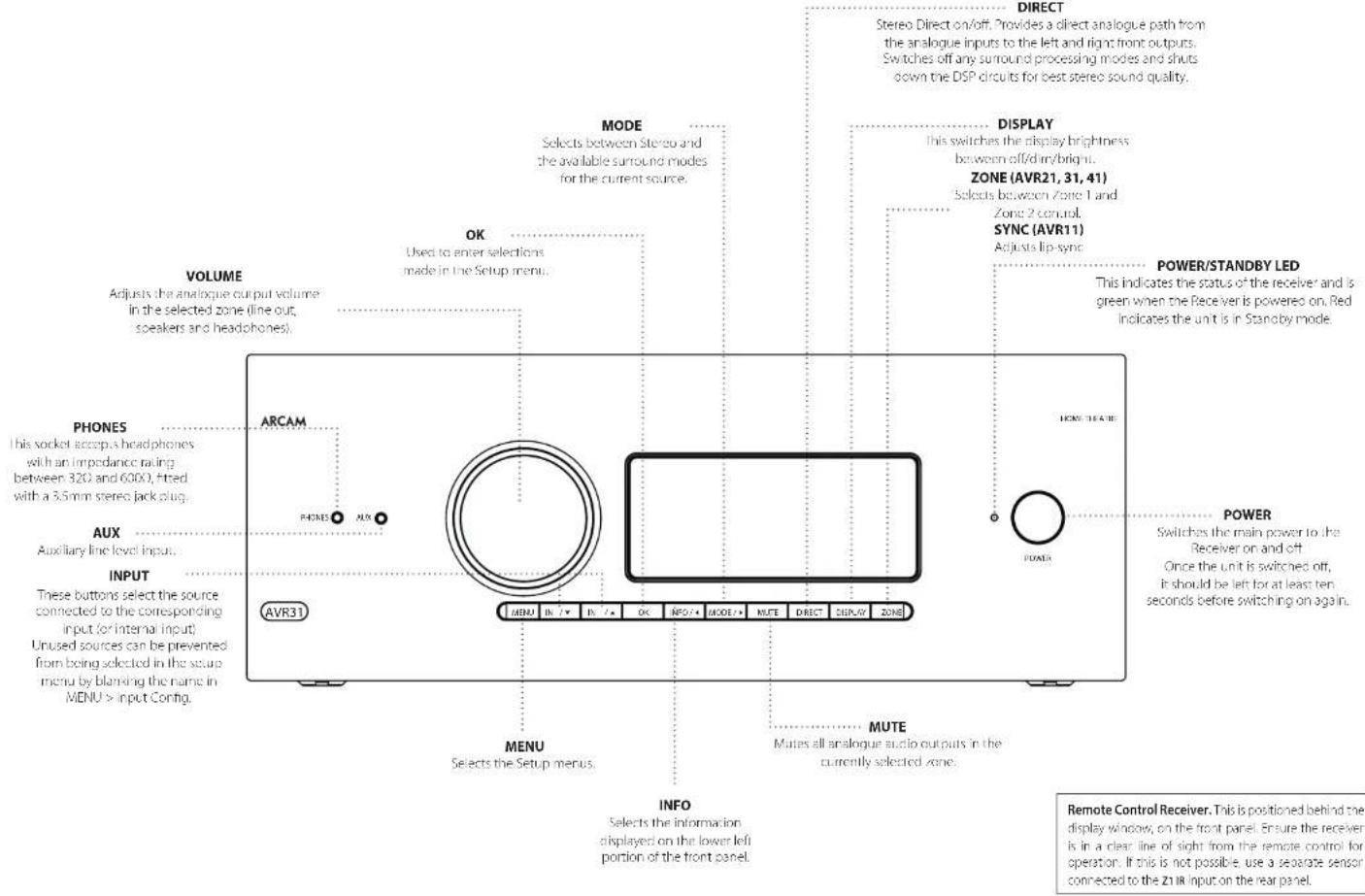
Stereo Direct
To listen to a pure analogue stereo input, press the DIRECT button. The Stereo Direct mode automatically bypasses all processing and any surround functions. In direct mode, digital processing is shut down to improve the sound quality and reduces digital noise with the Receiver to an absolute minimum.
Note: when Stereo Direct mode is selected, no bass management is performed, meaning that bass signals will not be redirected to a subwoofer.
Volume control
It is important to realise that the level of the volume indicator is not an accurate indication of the power delivered to your loudspeakers. The Receiver often delivers its full output power long before the volume control reaches its maximum position, particularly when listening to heavily recorded music. In comparison, some movie sound tracks can appear very quiet, as many directors like to keep maximum levels in reserve for special effects sequences.
Headphones
To use headphones with the Receiver, plug the headphones into the PHONES socket in the centre of the front panel.
When headphones are plugged into the front panel PHONES socket, the outputs for Zone 1 are muted and the audio will be down-mixed to two channels (2.0). The two-channel down-mix is required so that the centre channel and surround information can be heard via the headphones.
Extended front panel menu
Pressing the MENU on the Front panel and holding it for longer than four seconds will bring up the Extended Menu, allowing you to perform the following:
Restore to factory defaults
This option allows you to restore all settings on your Receiver to the defaults that it left the factory with.
Check for update
Checks for an over-the-air firmware update (requires external network connection):
This option allows you to restore all settings to their state as saved using the 'Stones secure backup' feature. This option is useful if settings are accidentally changed:
Store secure backup
This option allows you to save all the Receiver settings to a secure area of memory. If the settings can be retrieved using the restore option above.
Restore USB backup
This option allows you to restore all the settings from a file previously saved on a USB flash drive.
Store USB backup
This option allows you to save at the settings to a USB flash drive.
Region
Sett the regor you are incoed- Hortope, (Rm) US or Canada
Change remote code
The default BCS system code the Recover respondents is to 16. If required, for example due to another device in your system also using this BCS system code, it can be changed to 19. The supplied remote card can also be reprogrammed to use BCS system code 19 commands, see page EN-22.
Standby mode
"Auto" uses the power saving auto standby feature, which will cause the unit to go into standby after 70 minutes if no signal is present or user input occurs. "manual" allows the user full control of when the unit gets into standby.
Protection sensitivity
This option allows adjustment of the protection sensitivity of the power amplifier (not AW41). Caution should be used with this setting as it is deliberately configured for maximum protection and should only be adjusted when using speakers that are 'complex loads'.
Use display HDMI
If so, to "no" the Receiver will ignore the EIDD of the display and send all resolutions from the source through the Receiver.
Display type
Adjust the position of the OS0 depending on if a 169.8/21.9 display is being used.
Updating firmware via USB
The firmware in your receiver can be updated from a USB flash drive containing firmware update files.
You can download the latest firmware file, together with upgrading instructions from the Arcam website (www.arcam.co.uk).
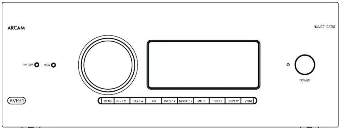
Front Panel Operation
[19
Remote Control
The universal remote controller
The Receiver is supplied with a so-called 'universal' backhaul remote control that can control up to eight devices. It is pre-programmed for use with the Receiver and many other Arcam products (FM/DAB tuners, CD players and 3D players).
With its extensive built in library of codes, it can also be used with thousands of third party audio-visual components TVs, satellite and set-to-boxes, PVRs, CD players, etc. See the list of codes at the back of this handbook.
It is also a learning/remote, so you can teach it almost any function from an old single-device remote.
Using the remote control
case keep in mind the following when using the remote protocol:
Ensure there are no obstacles between the remote control and the remote sensor on the Receiver. The remote has a range of about 7 metres, if the remote sensor is obscured, the 21 IR remote control input jack on the rear panel is available. Please consult your dealer for further information.)
Remote operation may become unreliable if sunlight or fluorescent light is shining on the remote sensor of the Receiver.
- Replace the batteries when you notice a reduction in the operating range of the remote control.
Inserting batteries into the remote control
- Open the battery compartment on the back of the handset. To do this, press the catch on the battery cover as indicated by the arrow on the catch and remove the battery cover.
- In situ two 'AAA' batteries, as indicated in the battery compartment
- Replace the battery cover. To do this, locate the lug on the battery cover into the corresponding hole on the short edge of the battery compartment. Now press the opposite end of the battery cover (with the catch) down so that the cover is flush with the main body of the remote and the catch clicks.
Notes on batteries:
1.1. Ineffective use of batteries can result in hazards such as leakage and bursting.
Do not mix old and new batteries together.
Do not use non-identical bacteria together although they may look similar, different bacteria may have different voltages.
Ensure the plus (+) and minus . ends of eq battery match the direction indicated in the battery compartment.
Remove batteries from equipment that is not go to be used for a month or more.
When disposing of used batteries, please comply with governmental or local regulations that apply in your country or area.
Useful information
Backlight
A backlight comes on for eight seconds whenever a key is pressed. This helps you use the handouts in subdued lighting conditions.
LED blinks
Short blinks indicate a valid key press.
Multiple short blinks convey information (such as a device code) or signal the beginning and successful completion of a programming sequence.
The symbol is used in the manual to indicate an LED blink.
Timeouts and unassigned keys
Time out - After 30 seconds the remote exits the programming state and returns to normal operation.
Stuck key timeout - After any key is pressed continuously for 30 seconds, this remote stops sending IR transmission to conserve battery life. The remote remains off until all keys are released.
Unassigned keys-the remote ignores any unassigned key presses for a particular Device Mode and does not transmit
Low voltage indicator
When the batteries are running down, the backlight flashes briefly whenever you press a button:
If this happens, fit two new AAA alkaline batteries as soon as possible.
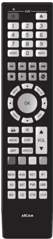
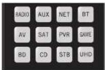
Device Mode/Source keys
As the remote can control your receiver as well as a range of other equipment. many of the buttons have more than one function depending on the device mode selected on the remote control.
The Device Mode keys (shown below) select the source on the Rescuer. If none of these keys is pressed,brically, a command is transmitted to change the source on the unit. Also the functionality of the remote control changes to operate the selected source device; it's like having a bundle of different remotes in your hand.
| HID | Internal F/M or DAB laser input |
| ALR | Auxiliary input |
| NET | Ethernet input (e.g. Internet radio) |
| WT | Bluetooth input |
| AV | Audio-visual input |
| SAT | Satellite input |
| PSB | Personal Video Recorder (or Digital Video Recorded) input |
| SMI | Games console input |
| BD | Blu-ray Disc or DVD player |
| CB | Compact Disc player input |
| SIB | Sci Top Box recorder input |
| UHD | UHD player input |
Each Device Mode changes the behaviour of many of the remote keys to control the source device; approximately, in this example, in CD mode 4 plays the previous CD track, but in AV mode 3 issues the IV [stream down] command.
The remote remains in the last selected Device Mode so it is not necessary to press a Device Mode key before every command key all you are doing is playing or skipping tracks on a CD, for example.
Navigation keys
The Navigation keys steer the cursor in Setup menus or on-screen menus. They also replicate the navigation functions of original remotes supplied with other home entertainment devices in your system. OK confirm a setting.
Volume control
By default, the remote is set up so that the volume control and mode button always control the volume of the Receiver, regardless of which Device Mode the remote is currently set for. This is known as volume 'punch through'.
For example, if you are listening to a CD, you will probably have the remote in CD Device Mode to control the CD player. You can use the volume controls on the remote directly to adjust the volume of the Receiver without first having to press AMP to put the remote into AMP Device Mode. The volume buttons 'punch through' the CD Device Mode on the remote to the AMP Device Mode.
Volume punch through can be disabled individually for any Device Mode I desired.
Customising the remote
he remote offices a Code 1 eaming feature that allows you to copy up in 16 functions from an original remote control onto the remote keyboard. For details of this, and other customisation features, see 'Customising the Remote' on page EN 22.
The remote complies with Part 15 of the FCC rules
This equipment has been tested and found to comply with the limits for a class B digital device, pursuant to part 15 of the FCC. Rules, those limits are合规 to provide a reasonable protection against harmful interference in a residential installation. This equipment generates, uses, and can radiate radio frequency energy and if not installed and used in accordance with the instructions, may cause harmful interference to radio communications. However, there is no guarantee that interference will not occur in a particular installation. If this equipment does cause harmful interference to radio or television reception, which can be determined by turning the equipment off and on, the user is encouraged to try to correct the interference by one or more of the following measures:
Scortien or relocate the receiving antenna.
Increase the separation between the equipment and receiver.
Connect the equipment into an outlet or a circuit different from that in which the receiver is connected.
Consider the dealer or an experienced radio/IV technician for help.
Customising the Remote
Code learning
The supplied remote comes with a complete library of pre-programmed codes. After you have set up the remote for your device, you may find that there are one or more functions on your original remote which do not have a place on the keypad. For convenience, the remote offers a Code Learning feature that allows you to copy up to 16 functions from an original remote control onto the remote keypad.
Before you start, make sure that:
The original remote control is working correctly.
The remotes are not pointing at your device.
The remoteshave freshbatteries.
The romeats are not in direct sunlight or under strong fluorescent lights.
NOTE
Learned functions are mode-dependent. You could assign up to eight different functions to a single key - a separate learned function for each mode.
Direct code setup (Method 1)
The first method is to program the remote with the 3-digit code number for the device you wish to control - see "device code tables". Make a note of the suggested number or numbers - the most popular code is listed first. Now power on the device.
Press the Device key for the product you want to set up, together with the key. Hold down both buttons for three seconds until the HD stays lit.
You are new in setup mode, and you can release the buttons.
2. Enter a 3-digit code for the device.
If the 8-digit code number you entered is correct for the device, it will turn off. If it doesn't turn off, enter the new code number from your list until the device does turn off.
3. Once you have found the correct code, press the Device key again. The LED blinks three times to confirm that the code has been successfully stored.
Library search setup (Method 2)
Library search allows you to scan through all the codes contained in the remote's memory. It can take a lot longer than the previous method, so only use this method if:
- Your device does not respond to the remote after you have tried all the codes listed for your brand.
-
Your brand is not listed at all in the Device Code tables.
-
Press the Device key for the product you want to set up, together with then key. Hold down north buttons for three seconds until the LED stays lit.
- Point the remote control at the product you wish to control and press the or button on the navigation pad. Each time the or button is pressed, the code counts up (for down) one code number with a sigma to power off the device.
3.Continue pressing the up or down button, in approximately one second intervals, until the device turns off. DO NOT alternate the up and down buttons - you need to move in only one direction.) - to store, he correct code, press the device key again. The ID blinks three times in confirm that the code has been successfully scored.
Learning setup (Method 3)
The third method involves 'teaching' the Arcam remote from the original remote for the device. The two remotes should be facing each other, about 10cm apart.
- Press the Device key for the product you want to set up together with one key. Hold down both buttons for three seconds until the LED stays lit.
- Press the button on the Arcan remote that you want to assign a command to. The LED links once indicating that the remote is ready to learn the command.
- Press and hold the appropriate key on the other remote until one 1+0 blinks twice . . . . . . This indicates the Arcam remote has learned the command from your other remote.
-
Continue Learning the commands from your other remote by pressing the next button on one remote and repeating steps 2 and 3.
-
Once the remote has learned all the selected commands, press and hold the Device key you used to enter learning together with the Numeric key to score the learned commands.
NOTE
If the Arcam remote LED blinks five times
there was an error in the learning process. In this case, please start the Learning Setup from the start.
TheAard keysdo notleam commands.
Important notes
Once you start a Code Learning session, you have approximately ten seconds to conduct each step. Any longer, and a much more means that you'll have to start the process again.
The Learning feature is mode-specific - you can copy one feature per mode onto a key.
The remote can learn approximately 16 functions in total.
To replace a learned function, simply assign a new function to the same key.
- Learned functions are retained when you change batteries.
Code Learning fails, try altering the distance between the two remotes, make sure that the ambient light is not too bright.
Deleting the learned data
To delete all the learned data for a device:
- Press the Device key for the product you want to sell up, together with the 3 key. Hold down both buttons for three seconds until the LED stays lit.
- Press and hole down the Device key for the product that you went to erase, together with the key for three seconds until the 1+0 blinking twice.
-
If no further key presses are made for 3D seconds after the LED oinks twice, the remote leaves erase mode without deleting the learned data.
-
If you press the Device key together with the key one more time within 30 seconds after HD blinks twice, you can finish the erase mode deleting all the data learned on the Device. The LED blinks three times to confirm.
To delete the learned data for a key for a device:
- Press the Device key for the product you want to set up, logon with the key. Hold down both buttons for three seconds until the LED stays lit.
- Press and hold down the key on which you want to delete the data for three seconds. The LED blinks twice if any further key press is made; the remote escapes from erase mode without deleting the learned data.
- If any further key press is not made for 30 seconds, the I-H2 clinks twice 12 the retrograde escapes from the crate made automatically without deleting the scanned data.
- If you press the Device key together with the 3 key again within 30 seconds after the I-EO blinks twice, all the data learned for that Device is deleted and you have erase mode. The LED alinks three times In confirmation.
Reading stored code numbers
- Press the Device key for the product that you want to set up together with the 4key, Hold down both keys for three seconds until the ID blinks.
- Press the INOy and count the number of blinks (一 = 1,二 = 2,三 = 3 etc.There is a time gap between digits.(Note that 0^ is represented by ten blinks.
Locking/Unlocking a specific Device Mode
When you first unpack your remote and insert the batteries, it is able to control certain Arcam components automatically (e.g. BD players, Amplifiers, Tuners and CD players). We achieve this by programming specific Arcam device codes onto the relevant Device Mode keys, then locking the Device Modes so you don't reprogram them inadvertently.
If you want to override these locked default settings - to control a third-party BD player, for example - you will first need to unlock BD Mode before setting up the remote using one of the learning methods described on the previous page.
Here are the factory default settings:
| Device Mode | Default status | Default codes |
| AMP | Locked 00 | ( Arcam code 16) |
| BD | Locked 00 | ( Arcam) |
| AV | Unlocked 108 (Philips TV) | |
| UHD | Unlocked C code learning only | |
| GAME | Unlocked C code learning only | |
| STB | Unlocked 030 (Bushy/Goodman/ Grundig, from SAT database) | |
| SAT | Unlocked 128 (Sky+ Digital, from SAT database) | |
| PVR | Unlocked 08 (Humax PVR, from SAT database) | |
| CD | Locked 00 | (Arcam) |
Alternative codes are available for multi-room solutions, or in the case of code clashes with other manufacturer's products.
For example:
AMP(system code 19):002
Note that you need to change the system code on the product you wish to control, as well as the remote.
- AMP, BD and CD are the Device keys that may be Locked or Unlocked. Lock and Unlock are toggles (they change from Lock to Unlock to Lock, etc).
- Press and hold the Device and @keys together for three seconds.
The power HD says it, showing that it is in lock/unlock setup mode. - If there is no further key input for 30 seconds, the LED goes off and the remote leaves Lock/unlockset up mode.
- To toggle the status of a device and then verify the status of a device, press the 100% in sequence.
If you have locked the device, the LED blinks three times.
If unlocked the device, the LED blinks five times
5. If you press a valid Device key within 30 seconds, the 1.D link three times: and the remote leaves 1ock/unlock setup mode.
Controlling the volume of other devices
By default, the volume keys and mute key control the amplifier volume.
You can configure these buttons so they send volume commands to another device. In the following example, the volume commands are sent to a linked AV device (your television, for instance):
1. Press AV for three seconds, until the LED lights and stays on.
2. Press WOP
3. Press Again. The first three times
The volume and mute keys will now send the volume commands to the TV.
To set the volume buttons to control the amplifier once more, repeat the above steps, except pressAMP in step 3.
Hidden commands
| Command | Effect |
| AMP+ | Sends a Power On command |
| AMP+ | Sends a Power Off command |
| AMP+OK | Sends a Zone command |
| AMP+ | Cycles through HDMI outputs 1, 2, 3&2 |
| CD+ | Sends a Power On command |
| CD+ | Sends a Power Off command |
| BD+ | Sends a Power On command |
| BD+ | Sends a Power Off command |
| BD+ | Sends a Resolution command |
Factory default reset
You can reset your remote to the original factory default settings.
Press and hold both the (home) and MENU keys for about five seconds until the power LED blinks five times
All programming and setup codes that you have entered into the remote are erased and the remote returns to the original factory default settings.
Device codes
The tables that are in the final section of this Handbook list 3-figure codes for different manufacturers' devices.
Use these when setting your remote up to control your devices, as described in Direct code setup: Method 1 (see previous page).
If more than one code number is listed, try the first number. If the results are unsatisfactory, continue trying the numbers for that manufacturer to get the best fit with the functionality required.
If the manufacturer of your equipment is not listed, you can try Library search setup: Method 2 (see previous page). This method allows you to scan through every code contained in the remote's memory.
AMP
AMP Device Mode
The Advice Mode button configures the remote to control the Receiver. Pressing this button does not affect the currently selected input on the Receiver.
The functionality of the remote is centric sensitive for the internal sources and is described in the following table.
| Single press - Toggles Receiver power between standby and on in the current zone (zone in which the command is received). Press and hold - Forces all zones into standby. regardless of which zone the command was received in. | |
| L.D | The number keys can be used for direct entry of numeric values |
| SMC | Sync. Delays may be introduced into the video signal by video processing which causes a mismatch between the audio and video timing. You will not see this by speech sound being out of synchronization with the liu movements in the video, to compensate for this, you can adjust the liu sync delay. Press the synchon- and use the ① and ② navigallum buttons. Press again to exit the liu sync trim menu. |
| HIO | Into cycles through the information displayed on the lower left portion of the front panel display when on TUNINET input/USB |
| Brings up the DTSK dialogue control adjustment. | |
| VIO | Displays the unit's setup menu on the On Screen Display. |
| TUGER | Toggles Dialby Audio Processing. |
| AIOB | Toggles Dialby Live EQ on/off. |
| STM | Brings up a temporary subwoofer rim control. Use the ① and ② navigation buttons. Press RTN again to exit the sub trim control. As this is a temporary adjustment, the sub trim level is reset to the value set in the Speaker Levels menu when the unit is turned off or put into standby. |
| T | Toggles the music function of the AVR. |
| VST | Adjust amplifier volume. |
| MST | Cycles through the available surround and downmix modes. |
| OFF | Cycles through the front panel display's brightness options. |
| AVR | Reset remote to AMP mode. |
| MOT | Screw direct on/off. Provides a direct analogic path from the analogue inputs to the left and right front outputs. Switches off any surround processing modes and shuts down the DEP circuits for the best stereo sound quality. |
#
Navigate the files and menus on the screen.
0 selects the highlighted file or enters the highlighted menu on the screen equivalent to 'Enter' or 'Select' on some remote controls.
Up
L
Right
Down
AMP Power on from Standby
AMP Standby from Power on
AMP OK select Zone 2
Network commands
| #0 | Red button. |
| #FFH | Green button. |
| #FFG | Yellow button. |
| #UE | Blue button. |
| #20 | Tuner input. |
| #5 | Aux input. |
| #7 | NET input. |
| # | ST input. |
| # | AW input. |
| # | SAT input. |
| # | PWR input. |
| # | Game console input. |
| # | BD input. |
| # | CD input. |
| # | STB input. |
| #D | UHD input. |
When using the network client, the keys below are used to navigate music files in AMP Devices Mode.
| Suggests the previous/next track in the current playlist. | |
| Pause and playback of the current track. | |
| Stops playback. |
BD
BD/DVD Device Mode
The 8Device Mode button configures the remote in control the functions of Arcane Bluay Disc and 1900 players, although this can be changed. Pressing this button also selects BD as the source.
| Loggers power between stnancy and ran. | |
| ▲ | Open/close disc tray. |
| 1.5 | Searches for and plays the track corresponding to the key pressed when playing a CD. |
| REF | Cycles through the front panel display's brightness options. |
| 0002 | Cycles through the repeat options (track, disc, etc.). |
| ← | Fast rewind. |
| → | Fast forward. |
| ← | Press and release to skip back to the beginning of the current/previous track. |
| → | Press and release to skip forwards to the beginning of the next track. |
| ■ | Stop playback of a BD or DVD. |
| ■II | Pause and playback of the current track. |
| ● | Start recording (on products that have this feature). |
| #EM | Disc menu. |
| #LP | Activators BD/DVD player menu if available. |
| Navigate setup and BD/DVD programme selection menus. OK selects the highlighted file or enters the highlighted menu on the screen - equivalent to Enter or Select on some remote controls. ▲ Up ● Left ● Right ● Down BD +▲ Power on from Standby BD +▼ Standby from Power on BD -▼ changes the picture resolution (for BD, only on the Home screen). | |
| Returns navigation to the top level of the menu ("Home"). | |
| Changes audio decode format (Dolby Digital, DTS, etc.). | |
| AVI | Retries remote to AMP mode. |
| IPD | RED button for BD |
| GREEN | GREEN button for BD |
| YELLOW | YELLOW button for BD |
| BLACK | BLUE button for BD. |
AV
AV Device Mode
The AVDeVic mode button configures the remote to control the functions of a television or other display device. You will need to configure this Device Mode to work with your equipment. Pressing this button also selects AVS the source.
| Toggles power between standby and on. (Some TVs require you to use a number key to turn them on) | |
| Functions as original remove number key usually for channel selection. | |
| Display INFO or OSD (On Screen Display) function, if available. | |
| AV: this function is TV specific. | |
| Channel down. | |
| Channel up. | |
| Displays picture information; this function is TV specific. | |
| Guide. | |
| Navigates setup and programme selection menus. OK confirms a selection (equivalent to Enter or Select on some remote). | |
| Returns navigation to the top level of the menu (Home). | |
| Resettes remote to AV mode. | |
| RED key for Text TV | |
| GREEN key for Text TV | |
| YELLOW key for Text TV | |
| BLUE key for Text TV. |
UHD
UHD Device Mode
The UHD page allows code learning from a dedicated UHD remote - see "Customising the Remote" on page EN-22
CN-25
STB
STB Device Mode
The STIycc Mode button scrots as the source. If configured to work with your set top clock decoder device, the remote can subsequently control the dev
| Logges power between standby and on. | |
| 0.5 | Functions as original remote number key usually for channel selection. |
| 100 | Display INFO or OSD (On Screen Display) function, if available. |
| 5000 | Selects the Library or Media function. |
| ← | Rewind. |
| → | Press Forward. |
| < | Channel down. |
| < | Channel up. |
| ■ | Stop playback. |
| >II | Pause and playback of the current track. |
| ● | Record. |
| #0 | Opens the EPG (Electronic Program Guide) on some satellite and cable set top boxes. |
| POPUP | Turns on the Menu function if the set top box uses this feature. |
| ● | Navigare setup and programme selection menus. OK confirms a selection (equivalent to "Enter" or "Select" on some remote). |
| ● | Returns navigation to the top level of the menu ("Home"). |
| A#TR | Selects the Help function. |
| AVR | Reset remote control AMP mode. |
| #0 | RED button for set top box. |
| GREEN | GREEN button for set top box. |
| YELLOW | YELLOW button for set top box. |
| BLUE | BLUE button for set too box. |
SAT
SAT Device Mode
The device Name button selects as the source. If configured in work with your satellite receiver, the remote can subsequently control the device
| Toggles power between standby and on. | |
| - functions as original remote number key - usually for channel selection. | |
| TF | Display (NFO or OSD) (On Screen Display), function, if available. |
| Channel down. | |
| Channel up. | |
| WD | Displays programme information. |
| PON | Guide (or Setup) on some set top boxes. |
| Navigate setup and programme selection menus. OK confirms a selection (equivalent to "Enter" or "Select" on some remotes). | |
| Returns navigation to the top level of the menu ("Home"). | |
| IM | Back. |
| MT | Resets remote to AMP mode. |
| BD | RED button for Satellite. |
| GREEN | GREEN button for Satellite. |
| YELLOW | YELLOW button for Satellite. |
| BLUE | BLUE button for Satellite. |
PVR
PVR Device Mode
The PTV device Mode button selects a source. It is configured to work with your personal (hard disc) video recorder or similar device, the remote can subsequently control the device.
| Toggles power between standby and on. | |
| L2 | Functions as original remove number key – usually for channel selection. |
| M0 | Display NFO or OSD (On Screen Display) function, if available. |
| M20 | Selects the Library or Media function. |
| ← | Rewind. |
| → | Fast Forward. |
| ↑ | Channel down. |
| ↑ | Channel up. |
| ■ | Stop playback. |
| ■II | Pause and playback of the current track. |
| ● | Record. |
| mms | Opens the EPG (Electronic Program Guide) on some satellite and cable set top boxes. |
| RFLP | Turns on the Menu function if the PVR uses this feature. |
| Navigate setup and programme selection menus. OK confirms a selection (equivalent to 'Enter' or 'Select' on some remote). |
| Returns navigation to the top level of the menu ('Home'). | |
| Selects the Help function. | |
| Resetset remote to AMP mode. | |
| RED button for PVR. | |
| GREEN button for PVR. | |
| YELLOW button for PVR. | |
| BLUE button for PVR. |
CD
CD Device Mode
The CDevic Mode buitian selcs a 0hce source
The Burton is configured to control the CD functions of Arcam CD players, although this can be changed (see "locking/unlocking a specific Device Modes" on page 19.23).
| Loggers power between standby and active. | |
| ▲ | Open/close disc tray. |
| ▲ | Searches for and plays the track corresponding to the key pressed. |
| STEP | Cycles through the front panel display's brightness options. |
| WOOZ | Cycles through the repeat options (track, disc, etc.) |
| ← | Fast rewind. |
| → | Fast forward. |
| ↔ | Press and release to skip back in the beginning of the current/previous track. |
| || | Press and release to skip forwards to the beginning of the next track. |
| ■ | Stop playback of a CD. |
| ||| | Pause and playback of the current track. |
| nUP | n'normal play' i.e. the display does not show the letter P), press the ↑ and ↓ keys to select the track and then MENANTS the track. n'program play' mode, noMENANTS deletes the stored track. |
| Navigate setup and CD programme selection menu. OK selects the highlighted file or enters the highlighted menu on the screen - equivalent to 'Enter' or 'Select' on some remote controls. A Up C Left B Right D Down CD + A Power on from Standby CD + B Standby from Power on | |
| MY | Review remote in AMP mode. |
| E200 | Plays the programmed packs. |
[1N-27
Essential Setup
Before you use your Receiver it is essential that you enter some information into the Setup menus about your speaker configuration. This allows the Receiver to process any surround sound if digital source to exactly match your system and give you the ultimate surround sound experience.
There are three pieces of vital information which are outlined in the sections: 'Speaker Types', 'Speaker Distances' and 'Speaker Levels'.
The way you enter this information manually into the Receiver is given later in the Setup Venue section on page HN-30.
When calibrated using Dirac Live room equalisation the speaker levels and delays will be established automatically and apoed when the equalisation is turned on, speaker types however must be manually entered. For use with equalization turned off, the speaker size, speaker distance and speaker levels settings must be entered manually. It is important to understand why these speaker settings must be entered, which is why this section is presented before the section on equalisation."
Speaker types
You need to set the type of speakers that you have connected to you: Receiver.
Large capable of full frequency range reproduction Small not capable of full frequency range reproduction at the low frequency end
None speaker not present in your configuration
The terms 'I agree' and 'Smell' do not necessarily relate to the physical size of your speakers. As a rule of thumb, if a speaker cannot reproduce a flat frequency response down to about 40Hz and very few clicks it is often better to consider them as 'Smell'. For setup purposes of home cinema,
When a speaker is set to 'Small', very low frequency sounds are redirected away from that speaker to a 'Large' speaker or a subwoofer, which are far better suited to reproducing these low frequency sounds.
Note that it is not possible to set all speakers to 'small' unless there is a subwoofer in your speaker configuration. If you do not have a subwoofer, you will be forced to set your front speakers to 'large'.
(Advanced users may wish to automatically override the 'Small' speaker setting for purely stereo music listening when not watching movies. This can be achieved in the 'Input Config' menu - see page EN-31).
Crossover frequency
If you have set any speakers as being Small, then you will be required to set a value for the crossover frequency. This is the frequency below which signals are filtered away from these Small speakers and redirected to large speakers or the subwoofer (if present). A frequency of 80Hz is often a good starting point, however you will probably have to experiment with different values to find the best value for your system or consult it your speaker handbook.
Use Channels 6+7 for
If not used in the main zone, it is possible to assign the Surround Back channels to Height 1, bi-amp the Front Left/Right channels or to provide an armful output to Zane 7.
Speaker Levels
Finally the levels of all the speakers in the system need to be adjusted to match each other at the listening position, again to create a proper surround effect. To help with this the Receiver can generate a test noise for each speaker which should be measured with a sound pressure level (SPL) meter. The meter should be set to C^* weighting and slow response. Several smartphone/tablet apps are available which can also perform this function. The level of noise measured at the listening position from each speaker should be adjusted on the Speaker Trims page of the Setup menu so that the meter reads 75dB SPL. It does not matter what the system volume setting of the Receiver is before turning the test noise on as the volume setting is over/indoen for the duration of the speaker noise test.
There are several basic SPL meters on the market at reasonable prices aimed at home cinema enthusiasts. Check your local technology store, search online or ask your dealer. If you do not have an SPL meter or suitable app, you can try to adjust the noise level of each speaker by ear. In this case it is not possible to adjust the speakers to the absolute 75dB SPL volume level, but you should aim for all speakers sounding equally loud. Setting speaker test noise levels by ear is not recommended as it is very difficult to do accurately, but is often better than doing nothing at all.
Speaker Distances
It is essential for the distance from each speaker to the listening position to be accurately measured and entered into the Setup' menu. This ensures that the sounds from the various speakers arrive at the listening position at the correct time to recreate a realistic surround effect. The distance can be oriented in coordinates or inches.

DIRAC
Dirac Live for Arcam
There is a proprietary automatic loudspeaker calibration function built into your receiver from Dirac Research. Using a PC/MAC based application, this attempts to set the essential speaker settings for all the speakers in your system. It also calculates room equalisation (Room ^ ) fit values to remove some of the worst effects of resonant frequencies in the listening room.
Your Receiver package is supplied with a calibration microphone, which should be inserted into a USB socket on a PC or MAC connected to the same network as the Receiver and positioned as directed by the Dirac Live PC/MAC application. This microphone picks up the special calibration tones generated by the source when Dirac Live application is run. The Receiver then analyzes the signal and computes:
speaker delays,
speaker level,
problem resonant frequencies in the room while need control by filtering.
To help the system be as accurate as possible when performing Dirac Live setup, there are a few guidance rules that should be followed:
Minimise any background sounds in the listenin room and other nearby rooms.
- Close all windows and doors in the listening room.
- Turn off all fans including air-conditioning systems.
Mounting the microphone on a tripod or similar.
Position the set up microphone pointing upwards roughly head height when sat in the normal listening position. It is not necessary to point the microphone directly at the speaker generating the test tone, the microphone should be pointing vertically towards the ceiling. (It helps if you are able to position the microphone exactly where your head would normally be for listening, with the microphone in direct unobstructed view of all speakers.)
If your system includes an active subwoofer, set by setting its output level / gain control to a value roughly matching the front speakers.
When activated, a calibration tone is played through each channel of the Receiver in turn, including the subwoofer channel. The calibration tone cycles round each of the speakers multiple times as the different parameters are calculated. Follow the 'progress' information on your PC MAC.
By default, Room EQ is not applied to any of the source Inputs. You should enable Room EQ on inputs you think benefit from this feature, as required, by listening when playing typical source material through each input. After being calculated, this is enabled from within the input Config menu.
While room equilibration can help to reduce problems with listening room acoustics, it is usually far better to try to solve these problems with the room directly. Proper loudspeaker positioning, acoustic wall treatments and moving the listening position away from walls should produce far better results overall. However, it may be difficult to do this in a home environment, so Room EQ is your next best choice.
atProblems
We advise you to look over the reported measurements on the screen following Dirac Live setup for any obviously incorrect results, in particular to ensure the reported speakers match your configuration and that the speaker distances to the listening position appear look roughly correct. If the results are not what you expected we can run Dirac Live setup. The Dirac Live setup function is normally quite accurate but occasionally false results can be generated. Problems may be as a result of
external sounds or rumbling/handling noises pick up by the microphone
square reflections offard surfaces (e.g., windows walls) close to the listening position.
1 very strong acoustic resonances within the room,
1 obstacles (such as a sofa) between speakers and in microphone.
If you are still experiencing difficulties or you wish to have the most accurate results for ultimate turnaround performance, we recommend using the manual method of establishing speaker distances and levels.
Using subwoofoers
If your system includes active subwoofoRs you may need to set the subwoofer output level/gain control set to a higher or lower value.
Please refer to the Dirac application and quick start guide for full details of how to use the system with your Recover.
Downloading the Dirac Live application
To download the Dirac Live PC/MAC application and quick start guide, please visit:
Using Dirac
You can store up to three Dvac EQ curves in the Receiver. Each input can use a different curve, for example a "Movie" curve on the BD input and "Music" curve on the CD input.
This can be set on a per input basis using the AUDIO
The remote.
Alteratively use the Room EQ menu item in the Audio settings menu to set the curve for each input. See "Room EQ" on page 一 N 31.
Note: When Dirac is run for the first time, the curve will be applied to all inputs. Subsequent curves will not be automatically applied, use the methods above to choose the required curve for the input question.
for AVS5 an additional license and calibration kit are required, please visit:
live.dirac.com
Setup Menus
The Setup menus allow you to configure all aspects of your Receiver. The next few pages will go through the menu items and explain their functions. The Setup menus will probably look quite daunting if you are new to setting up home cinema, but, the majority of them need only be configured once when you first install the system (or if your system changes or you move house!).
Entering Setup mode
To enter the setup menu, press the MENU on the remote control or font panel. The font panel display shows the setup menu (splitware right).
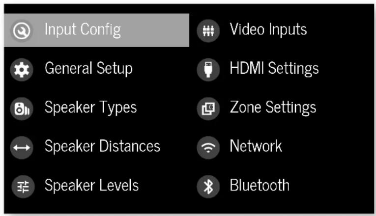
Navigating the setup menu
... using the remote control
The setup menu can be navigated by using the cursor (arrow) keys on the remote control. This is by far the easiest method.
- To enter the setup menu, press the MENU (which is located immediately under the navigation buttons).
- Use the and keys to navigate up and down the main section headings.
-
Once you have the main section that you require highlighted, use the key to enter the section.
-
Use the and keys to navigate up and down the section settings in the right-hand panel. Some settings may be grayed out. These are either for information only (e.g. incoming sampling frequency) or are not currently selectable. Scroll bars on the sides of the right-hand panel indicate your position in the settings list where there are more items than can be displayed at once.
- PressingOeolecs is a setting to change it, pressing OK again de selects the setting.
- At any time, press the mENTION to exit the menu. Any changes to settings are saved.
... using the keys on the front panel
The Receiver front panel controls can be used to configure the unit. Follow the instructions for using the remote control, in this case using INNOLDN, for INPUT left INFO and MOutlight.
Input Config.
The audio and video settings on this page of the Setup menu can be tailored specifically and independently for the currently selected input.
When a different input is selected on the input line, all the input-specific settings for that input are displayed below it. These settings are applied to the named input only and are stored in memory and recalled each time the unit is powered up and whenever that input is selected.
Input - The currently selected input connectors to which the settings below are:
Name The display name of the input. You can change the name of any input to more closely match your setup. For example, if you had two satellite receivers, you could connect the main receiver to the Sat audio and video input connectors and change the Name to 'SAT 1'. You could then connect the second satellite receiver to the UHD audio and video input connectors, but change the UIID Name to 'SAT 2'. It is then clearer to users of your Receiver which inputs they wish to select when scrolling through.
Lip Sync - each input can have its own scaling to add a time delay between the audio and video signals to compensate for the sound and picture not being synchronised. This is normally required when video processing is used in the system for scaling or de-interlacing video. The range of lip sync delays is 0 to 250 milliseconds.
The lip sync adjustment can on y correct for delayed video. If the audio is late set lip sync to :s minimum.
Mode Set the initial audio decode mode for stereo sources on this input.
Last Mode recalls the last used setting for this in p when a stereo source was applied. See section "Two-channel source modes" on page EN-35 for more information.
MCH.Mode - Sets the initial audio decode mode for multi-channel digital sources on this input.
- Last Mode recalls the last used setting for this in when a stereo source was applied. See section "Multi-channel source modes" on page EN-35 for more information.
Bass -
Treble -
These allow you to alter the bass and treble tone controls for all currently active speakers for each individual input. For example, if your PVR source sounds a little bass light, you can always correct for this by selecting PVR on the input line at the top of this menu and edit 2 or 3d8 to the Bass control. Then, whenever the PVR input is selected, the bass is automatically aposted for as long as that input is selected.
Room EQ- When the PIac Live application is run and EQ filters are downloaded into one of the three slots available, this can be selected.
Not Calculated: (Information only) There are no KQ filters, so cannot be selected.
Project Name: Dirac Live Room EQ is applied to the current source and will display the name of the project from the Dirac Live application.
1 Off: Dirac Live Room HQ is not applied to the current source.
Input Trim - Sets the maximum analogue input signal level (sensitivity) on this input before the ADC (Analogue-to-Digital converter) signal path choices. Options are 1, 2 and 4 volts RMS maximum input. The default is 2Vrms maximum. For example, analogue sources with low output levels may benefit by choosing the 1V maximum setting. This helps maximise signal to noise performance of the Receiver and also helps keep the various analogue sources sounding about the same level for any given Receiver volume control setting.
Dolby Audio Processing - Applies Dolby Audio Processing to the incoming audio.
Off (dc'ull) Dolby Audible Processing is not applied to this input.
Movetable for movie viewing.
Must be for music listening.
11 Nightpresses the audio to be more suitable for late night viewing or listening.
Stereo Mode - If you have configured your system to have a subwoofer, then you have the flexibility to choose how bass information is distributed between the front, side/right, speakers and the subwoofer when listening to stereo (two channel only) analogue and digital sources. Choose the option which gives you the most sound, even sounding bass. If you are using a subwoofer for stereo, please also see Sun Stereo below to set the level of the subwoofer. For best results test with a setup disc or live programme material. This setting can be used to override your normal speaker settings in the Sokr Types menu whenever the Receiver plays stereo material. It's quite common to find that two channel stereo music listening is best done with a slightly different subwoofer setting than for surround movies.
As Spkr Types: When an analogue or digital stereo source is played, your normal speaker configuration (as in Spkr Types menu) is used to reproduce the signal.
Left/Right: Full frequency stereo information. All audio is sent to the front left and right speakers only without any bass redirection. You can use this setting if you consider your front left/right speakers to be able to handle the full frequency range of music. If you have set your front left/right speaker size as Small in the Spiky Types setup page, you may wish to use this option to override the setting to Large for stereo music listening, if you have full frequency range left/right speakers. It can often be beneficial to set full frequency range speakers to Small in the Spiky Types setup page for use with movies, if you have a subwoofer in your system. Doing so may deliver more impact on movie soundtracks as subwoofer designs to handle reproduction of high bass content. However, you may find that for stereo music a better overall result is obtained by not using the subwoofer and effectively treating the front left/right speakers as Large.
Left/Right+Sub: Full frequency range stereo is fed to the front left and right speakers and extracted bass is sent up the subwoofer. In this case, the low frequency information is effectively duplicated.
Sat+Sub: Use this setting if you really do have Small satellite front left and right speakers, or if you prefer the overall sound of bass being handled by the subwoofer. Full bass management is used so that analogic and digital stereo sources are fed to the DSP where the bass is filtered off front left and right and redirected to the subwoofer.
NOTE: The Stereo Mode function is not available when using an analogue source in Stereo Direct mode.
Sub Stereo If Left/Right+Sub or Set+Sub is selected in Stereo Mode above, this setting adjusts the level of the subwoofer when the source is two channel stereo.
IMAXmode(AVR11,AVR21,AVR31,AV41)-Selects if IMAX mode is enabled from the incoming audio stream (auto) or forced on or off.
Auro-matic 3D (AVR11, AVR21, AVR31, AV41) - Selects the mode of the Aero-matic 3D upmode.
Small: Adjusts the upmixer for a small-sized room
Medium: (default) Adjusts the upriver for a medium-sized room
Large: Adjusts the upomixer for a large-sized room.
Movie: Adjusts the upmixer for him material.
Speech: Adjusts the upmixer to focus on speech reliability.
Auro-matic 3D Strength (AVR11, AVR21, AVR31, AV41)
Adjusts the amount of unprocessed to processed signal when using the Auto Automatic 3D upmixer.
Audio Source - Selects the particular connection type for each input. The default is HDMI for inputs with an HDMI connection and Digital for inputs without an HDMI connection. This setting must be changed if another connection is used.
Select from the list the audio type you are using on this
SOURCE
In HDM; the unit is forced to use the HDMI audio input for this source.
Li Digital: the unit is forced to use the optical (TOSLINK) or coaxial (S/PDF) digital audio input for this source
- Analogue: the unit is forced to use the analogue audio input for this source.
CD Direct Tums on/off the compressed audio detection mure delay. Your AVI mutes when it detects a change or break in a digital stream. This is intentional and prevents unwanted noise from being output from your speakers when using sources that change between multiple formats (e.g. a Blu ray player or TV Se; Top Box). CD direct can be activated when used with a source that will only transmit a consistent format (e.g. a CD player with PCM audiol). This will defeat the muting and prevent potential loss of the beginning of 'sacks where audio begins very promptly.
General Setup
General information and system controls.
Source Input - (information only) The currently selected input to which the settings below relate.
Incoming Format (Information only) The format of the digital audio stream connected to this input. If present.
Incoming Sample Rate (in information only) the sample rate of the digital audio stream connected to this input. If present,
Incoming Bit Rate Information only) The bit rate of the digital audio stream connected to this input. If present.
Dialnorm - Information only if a Dolby Dig to audio stream is connected to this input, this is the Dialogue Normalisation setting requested by the stream.
Incoming Resolution - Information only. Shows the incoming video resolution.
Audio Compression - Allows selection of compression which is ideal for late night listening. The compression effect increases the volume of the quiet passages and decreases the volume of the lounder passages. Compression only applies to Delay/DTS soundtrack formats that support this function.
Off: (default) no audio compression is applied.
RT Medium: compression is applied so that loud portions of a soundtrack are reduced in level. Dolby
True I.D stream is compressed automatically as set by the incoming sstream.
11 High: the maximum amount of dynamic range compression is applied, so that the difference between loud and quiet portions of a soundtrack is minimised.
I his titting applies to all inputs when a relevant digital audio stream is decoded. It is stored in memory and recalled each time the unit is powered up.
Balance - To alter the sound balance temporarily between front left and right speakers. You can alter the sound stage to either the left or the right by up to 605. Note that it is not possible to shift the audio signal completely over to one channel. This function resets to equal left/right balance when the input is changed.
DTS Dialogue Control Sets the level of the dialogue channel in compatible D1S audio streams.
Maximum Volume - Limits the maximum volume setting the system can be turned up to in the main zone. This is a useful feature to prevent accidental overdriving of low power handling speakers (for example). It is stored in memory and recalled each time the unit is powered up.
Max On Volume - limits the maximum volume the system operates in the main zone when it is switched on or comes out of Standby. The system comes on at this store volume setting if the last used (possibly very loud) volume exceeds this value. It is stored in memory and recalled each time the unit is powered up.
Display on time Sets the time that the front panel display remains illuminated after receiving a command. The default is always on.
Control Enables or disabiloes RS232 or IP (NET) control, a system that allows control from various third-party home automation systems. Note, only RS232 or IP control can be used, not both.
Power on - Determines how the unit powers on. Stby: In Standby mode
On:On
Last state: Last state (defaul)
Speaker Types
Language Select the language for the menu wo English, French, German, Spanish, Dutch, Russian, Chinese.
Settings for the types of loudspeaker you have connected in your configuration. These settings are applied to all audio inputs and are stored in memory and recalled each time the unit is powered up.
Front Left/Right -
Centre -
Surr. Left/Right -
SurR Back L/R
Height Front
Height Back
Here you set the type of speakers that you have connected to your Receiver:
Large: capable of full frequency range reproduction Small: not capable of full frequency range reproduction at the low frequency end
1 None: speaker not present in your configuration
NOTE: It is not possible to set all speakers to Small unless there is a subwoofer in your speaker configuration. If you do not have a subwoofer, you will be forced to set your front speakers to Large.
NOTE: If there are only two ceiling height speakers connected, these need to be set as front, though can be placed either in front of, or above, the listening position.
Subwoofer configures the dedicated sub out terminals are used for a single subwoofer channel (using the two parallel ports).
Channel 13 & 14
Channel 15 & 16 -
Conjugates the speaker positions that channels 13, 14, 15 & 16 are used for.
Height Type - configures the type of height, speakers ceiling mounted or Do by enabled.
Use Channels 6+7 for - If your main zone speaker set up does not include Surround Back Left and Right speakers, you can choose to use the Surround Back amplifier channels as
the Height 1 amplifiers, to Bi-Amp the Front Left and Right pfc, or as a stereo power amplifier for Zone 7.
Filter Slope - Configures the filter slope used for bass management · 126.8, 24.8 , 36.8, 48.8, 56.8/octave
Sub Gain = configures the output level trim for all outputs configured as subcoolers in -6dB steps from 0dB to -30dB.
Speaker Distances
Calibration settings for the distances between the loudspeakers and the listening position.
NOTE: Speakers that are not present in your configuration will be greyed out.
If Dirac Live is used, these settings will be shown in time (ms) and not distance.
These settings are applied to all audio inputs and are stored in memory and recalled each time the unit is powered up.
Units - Select whether you wish to measure distances in Imperial or metric units.
Front Left -
Centre
Front Right -
Surr. Right -
Surr. Back Right -
Surr. Back Let
Surr. Left -
Left Top Front -
Right Top Front -
Left Top Back -
Right Top Back -
Subwoofer
Channel 13
Channel 14
Channel 15
Channel 16
As described in 'Essential Setup' on page EN-28, measure the distance from each loudspeaker in your system to your ear in the main listening position and enter the values. This allows the Receiver to calculate the correct relative delay for each
loudspeaker.
Speaker Levels
Calibration settings for the test noise signal level through the loudspeakers and measured at the listening position,
NOTE: Speakers that are not present in your configuration will be greyed out.
These settings are applied to all audio inputs and are stored in memory and recalled each time the un t is powered up.
Test Tone selects the internal test zone generator or allows the use of an external test zone from the currently selected HDVI input (e.g. pycled from a BDO).
Front Left
Centre
Front Right -
Surr. Right -
Surr. Back Right -
Surr. Back Left -
Surr.Left-
Left Top Front -
Right Top Front
Left Top Back
Right Top Back -
Subwoofer
Channel 13
Channel 14
Channel 15
Channel 16
Use the 空 and navigation buttons on the remote control to select the relevant speaker. Press 空 to enable/ disable the calibration noise and the 空 and navigation buttons to adjust the noise level from each speaker.
As described in "Essential Setup" on page EN 28, adjust the
level of the test noise from each speaker so that an SPL meter at Uc: listening position measures 7.0dB SPL.
Video Inputs
Settings to optionally assign a video source to each of the normally audio-only inputs.
These settings are stored in memory and recalled each time the unit is powered up.
Video Input CD
Video Input Aux -
Video Input FM
Video Input DAB -
Video Input Net :
Video Input BT -
The default for each of the audio inputs is 'None'. You could, however, associate 'Sat' video with FM or Digital Radio audio to receive radio commentary of a sports game with pictures from satellite coverage, for example.
HDMI Settings
The settings in this menu control the output resolution from the video processor in the receiver. These settings are applied to all video inputs and are stored in memory and recalled each time the unit is powered up.
Zone 1 OSD Selects whether the main zone 000-up OSD messages are On or Off. It is stored in memory and reca led eachtime the unit is powered up.
When on, all user adjustments that are made during the general use of the Receiver are displayed on screen as well as the front panel display. This includes the adjustment of volume, subwoofer level, I/O sync, I/O controls, etc. It is stored in memory and recalled each time the unit is powered up.
When Off, the above user adjustments will not appear on screen, only on the front panel display. This leaves the picture on your display device clear of pop up text. However, regardless of this setting the Setup menus are always displayed on screen.
Zone 1 Out - This setting controls the output for zone 1 from either output 1, output 2 or both.
Zone 1 Lipsync (Information only) Displays how much lip sync is automatically applied to the HDMI output to
compensate for video processing delays in the attached display devices. Not all display devices support this function.
HDMI Audio to TV - This setting controls the audio being sent directly to the TV.
HDMI Bypass & IP - This setting controls the functionality of HDM bypass & IP control which in standby. Selecting "low Power" (default) will mean that IP control (network) and HDM bypass are diseased. Selecting "HighDl&IP On" means that IP Control (network) & HDM bypass is enabled.
HDMI Bypass Source Selects which input is used for HDMI bypass function, e then a specific input or the last input used.
CEC Control Selects if CEC control is enabled on output 1. eARC Control - This setting enables/disables volume control from this display.
TV Audio This setting enables/disables auto-switching to eARC audio from the cisplay.
Power Off Control - This acting enables/disables auto power control from other CEC enable devices.
Zone Settings (AVR21, AVR31, AV41)
Lists the volume and control settings for Zone 2. These settings are applied to all audio inputs and are stored in memory and recalled each time the unit is powered up.
Z2 Input - Selects the input to be routed to Zone 7. The default is Follow Z1, i.e. the same source as currently selected in Zone 1.
Zone 2 Status - Selects if Zone 2 is in Standby or On.
Zone 2 Volume - The current volume in Zone 2.
Zone 2 Max. Vol Limits the maximum volume setting the system can be turned up to in the Zone 2. This is a useful feature to prevent accidental overdriving of low power handling speakers, for example.
Zone 2 Fixed Vol - the Zone 2 volume control can be locked at the current value for use with an external amplifier with its own volume control in Zone 2.
Zone 2 Max On Vol - Limits the maximum volume the system operates in the Zone 2 when it is switched on or comes out of Standby. The system comes on at this volume if the last used (possibly very loud) volume exceeds this value.
Connecting to a Network
Network
The Receiver is fitted with a network audio client which is capable of Airplay 7 and Chromecast built-in as well as stored music on a network storage device such as a PC, or on NAS drive.
The wireless network is configured using the Apple AirPlay setup or the Google Home app.
SSID (Information only) Displays the SSID the receiver is currently connected to, "wired" if a wired connection is used, or "not connected" if no connection is present.
IP Address (Information only): IP address assigned by the DHCP server, or if not using DHCP, the IP address you have assigned to http Receiver for your network.
MAC address - Information only; The unique address of the network card in your Receiver.
Friendly name - (information only) The network friendly name of your Receiver.
Bluetooth
The Receiver is fitted with a Bluetooth audio input.
Pair Device - Makes the Receiver discoverable by Bluetooth devices.
Clear Paired Device List - Cies the Receiver's list of paired Bluetooth devices.
Paired Devices - Displays a list of the devices paired with the Receiver.
In order to use the AirPlay and Chromecast built-in functionality of the Receiver you will need to connect it to your home network via a wireless or wired connection.
The following sections detail how to do this.
Note: before attempting to setup a wireless connection ensure the supplied wireless antennas are fitted to the antenna socket on the rear of the Receiver.
Home Automation Control
When connected to a network the Receiver can be controlled and monitored remotely using dedicated home automation software.
The same controls are also available via the RS232 input. Various third-party systems are available providing sophisticated control over all your entertainment devices. Contact your dealer or installer for details. The technical details of the remote control protocol are available upon request, by contacting Arcam at luxurysupport@harman.com.
For details of the available controls please refer to the control document which can be found at www.orcom.co.uk for further information.
AirPlay Setup
Wired Connection
Connect an ethernet cable to the Receiver
To listen to audio via AirPlay on your Receiver, ensure you Apple device is connected to the same network as the Receiver and simply select the Receiver as the AirPlay Audio playback device.
Note: The Receiver will appear as ArcCAM modelname.xxxxx in the AirPlay speaker menu, where xxxxx is the last 6 digits of the units MAC address.
Wireless Connection
Ensure your Apple device is connected to the wireless network you wish to connect the Receiver to.
Open the Wi-Fi settings menu on the Apple device and select the Receiver from the "Set up new AirPlay speaker" menu. Follow the instructions on screen. To listen to audio via AirPlay on your Receiver, ensure your Apple device is connected to the same network as the Receiver and simply select the Receiver as the AirPlay audio playback device.
Note: The Receiver will appear as AXCAM modelname xxxxx in the Airplay speaker setup menu, where xxxxx is the last 6 digits of the unit's MAC address.
Chromecast built-in Setup
Wired Connection
Connect anEthernet cable to the Receiver.
Wired & Wireless Connection
Download and open the Google Home application.


You should be prompted that there is a device available for setup. If not simply tap "Add" followed by "Setup a Device". Select the Receiver and follow the instructions on screen.
To listen to cast audio from any supported application on your Receiver, ensure your device is connected to the same network as the Receiver. Tap the Chromecast built in icon from within the application and select the Receiver as the playback device.
Note: The Receiver will appear as modeInarnic xxxxx in the setup menu, where xxxxxis the last 6 digits of the units IMAC address.
Spotify Connect
Use your phone, tablet or computer as a remote control for Spotify.
Go to spootify.com/connect to learn how.
Decoding Modes

Introduction
Your Receiver receiver provides all the key decoding and processing modes for analogue and digital signals, including the atest high definition audio formats over 100Mb/s.
Modes for digital sources
Digital recordings are usually encoded to include information about their format type. The Receiver detects automatically the relevant format in a digital signal such as Dolley Atmos, TrueHD, Dolby Digital Plus, DT5X, DT5-HD Master Audio, Auto 3D, Dolby Digital, or DT5 - and switches in the appropriate decoding.
Modes for analogue sources
Analogue recordings do not contain information about their encoding formats, so the desired mode - such as Dolby Surrogate - needs to be selected manually.
Mode memory
Dolly Digital or DTS audio (including the high definition formats) can be output in two mix modes, selected using the MODE button:
- Surround (e.g., five main channels plus a subwoo for a 5.1 source)
Stareo downmix.
Two-channel audio, regardless of whether it is analogue or digital can also be output in two mix modes, selected using the mode button:
Surround (e.g., Delby Surround, DT's NeuralX, etc.)
Stereo.
The Receiver stores the settings for each source. Thus the decoding mode for the following groups of source material can be stored independently:
- Dooby Digital (multi channel) and DTS source matrix
- Two channel Dooby, PCM or Analogue source code
Two-channel source modes
The following decoding and surround modes are for creating multi-channel stereo modes from 2-channel sources. They are available on the Recever for standard and high definition Dolby Dig tal 7.0, D1S 7.0, PCM or analogue sources:
Stereo -
16 Channel Stereo -
Dolby Surround
Dolby Virtual Height -
DTS Neural:X
DTS Virtual:X
Auro-matic 3D (AVR11, AVR21, AVR31, AV41)
Stereo
In this mode the Receiver works as a conventional high quality audio amplifier. Note that if the subwoofer is enabled in stereo mode, then some processing of the signal is carried out.
- Stereo Direct: this achieves the most direct signal path if an analogue correction is present.
16 Channel Stereo: this produces an output from all speakers by copying the left output to all left speakers and the right output to all right speakers. The centre speaker outputs a mix of left and right.
Dolby Surround
Midelay Surround allows the Receiver to derive up to 16 outputs from a two or multi-channel source to take better advantage of 3 amplifier and screwers in your setup.
Dolby Virtual Height
Dolloy Virtual Height creates an immersive audio experience by visualising height content over traditional speaker configurations without the need for height speakers. Note this mode is NOT available if height speakers are selected.
DTS Neural:X
DIS NeuralX is an advanced up-mixer that renders up to 47.4 channels of immersive audio from nearly any lower g.hannel count content.
DTS Virtual:X
DTS VirtualX creates an immersive audio experience by visualising height content over traditional speaker configurations without the need for height speakers. Note this mode is NOT available if height speakers are selected.
Auro-matic 3D (AVR11, AVR21, AVR31, AV41)
Automatic 3D creates an immersive audio experience by creating additional channels from the incoming audio to reach the available output channels, enhancing the listening experience.
Multi-channel source modes
Digital multi-channel source material is normally provided as '5.1 audio; the '5.1 channels' comprise of left, centre and right front speakers, two surround speakers and a low frequency effects (LFE) channel. Since the LFE channel is not a full range channel, it is referred to as '1'.
Surround systems decode and recodure the 5:1 channels directly. The D1S-h5 matrix enhanced decoding system creates one extra rear channel from information buried in the two surround signals of the 5:1 source. The CS enhanced system is sometimes referred to as a 6:1 system. This extra surround back channel is normally reproduced through two separate loudspeakers, creating a 7^7^ system.
DTS-ES discrete is a true 6.1 source, with six discretely encoded channels, plus the 5.1+ channel.
Dolly Digital Plus, Dolly TrueHD, Dolly Atmos, D15SX, DTS-HD, Aero 3D are high-resolution surround formats found on Blu-Ray discs
Decoding modes
The modes given in the following table are available for multi channel digital sources:
Special modes such as DTS-ES 6.1 discrete, Dolby Digital Plus, Dolby TruchoD, Dolby Atmos, DTSX, DTS HD and MAX ENHANCED. Auto 3D are only available from the correct source material.
High resolution audio sources
| Dolby Almos | Dolby Almos content is mixed as audio objects instead of traditional channels, so can take full advantage of the number and pacement of your speakers. |
| Dolby TrueHD | Provides up to 7.1 full channels at 50kHz, 24bit resolution, with potentially no losses in the compression process. Data rates can be up to 18Mbps. |
| Dolby Digital Plus | Provides up to 7.1 discographic channels of audio with less compression than traditional Dolby Digitalencoding. Data rates can be up to 6Mbps. |
| DTS-HD Master Audio | Provides up to 7.1 full channels at 50kHz, 24bit resolution, with potentially no losses in the compression process. Data rates can be up to 24.5Mbps. |
| DTSX® DTSX is a decoder package that renders immersive content which has been encoded with DTSX encoding. DTSX content consists of audio objects or a combination of audio channels and objects. The DTSX decoder package also plays back legacy DTS formats including DTS-HD Master Audio lossless and lossy streams. Supports greater than 7.1 channel output configurations (including height speakers) Provides "Dialogue-Control" so consumers can adjust the sound to their preference or the listening environment. Remaps any DTS content to any speaker layout Supports Blu-ray Disc (3D), DVD and streaming media formats, and legacy streams up to 192kHz Includes NeuralX, the latest upmixing/downmixing technology from DIS. | |
| IMAX FN-ANCHS (AVR11, AVR21, AVR31, AV41) | IMAX® Enhanced produces much the highest level of standards, ensuring the best color, contrast, clarity and sound on the market. These are products endorsed by IMAX to fully deliver the most immersive at-home entertainment experience and leverage the full quality and scale of IMAX Enhanced content. The IMAX Enhancer program introduces a new standard in home entertainment. |
| AURO 3D (AVR11, AVR21, AVR31, AV41) | AURO 3D is a decoder package that renders the audio at three levels -ear level, height level and the centre height level, creating an immersive sphere of audio. |
For Dolby Digital sources
| Dolby Digital 5.1 | Dolby Digital S.1 sources deliver sound with five discrete full range channels: left, center, right, surround left, surround right, plus LFE channel. |
| Dolby Digital Stereo Downmix Provides a stereo downmix of the source material for use with headphones. | |
| Dolby Digital S.1 + Dolby Surround | This mode is used to derive information for the individual surround back channels from the surround channels, using the Dolby Surround decoder. |
| For DTS sources | |
| DTS S.1 Less common than the Dolby Stereo Downmix Provides a stereo downmix of the source material for use with headphones. | |
| DTS E5.6 Matrix | This is a 6.1 channel format based on DTS S.1. It has the sixth channel matrix encoded into the surround left and surround right channels. The sixth channel is a surround centre channel and is directed to the surround back left and surround back right speakers. |
| DTS E5.6 Discrete | This is a pure discrete 6.7 channel sound format. DTS HS discrete mode operates only on sources with DTS E5.6 discrete audio decoding. |
| DTS96/24 Provides up to 5.1 channels | Audio of at 960Hz, 24bit resolution for superior sound quality compared to standard DTS 5.1 |
Tuner Operation
The Receiver is fitted with an TMODA0/DApR (digital) radio tumor. D4B broadcasts are not available in all locations.
This section deals with laser opacification, for information on setting up the timer and installing serials, see page EN-13.
The front panel will also give the same information, pressing the ING will cycle through the various items of information.
FM
Process mode (default)
Radiotext (if available)
□Programme type (if available)
DAB
□ Processing mode (default)
n Radiotext (if available)
□Fopamc type
Signal quality
Bit rate of transmission
Tuning/Channel Selection
When switching to the internal TUNER source, the Receiver enters the last used tuner bands, be it -M or DAB. Repeatedly pressing RADIOs through the available tuner bands on your Receiver.
FM analogue radio
Frequency tuning on FM radio is performed using the ⑥ and ⑦ buttons on the remote control in TUN device mode. Individual presses move the frequency down and up one step. If you press and hold either of the tuning buttons for two seconds, the laser scans to the next strong signal. You can step a scan at any time by pressing one of the tuning buttons again.
In Europe, the internal FM radio is capable of receiving RDS (Radio Data System) radiosex signals that are transmitted on some stations. The RDS information typically includes the radio station name, the music or speech genre as well as additional information related to the current programme. On music stations this is often information on the currently playing track.
DAB digital radio
Digital Audio Broadcasting (DA) has become more widely available. See www.worlddab.org/country_information for information on DA availability.
You will need to scan for available stations before being able to listen to them.
To scan for DAB stations, first select the DAB timer then press and hold until the display indicates scanning has started. The Receiver will then scan all the DAB radio frequencies and compile a list of the stations that are available.
When the scan is complete, you can scroll through the station list using the + and + buttons on the remote control. To listen to the currently displayed station press the + if you do not press + within two seconds, the display will revert to displaying the currently waiting station.
Saving and selecting Presets
Preset selection uses the and keys on the remote to browse and to select the preset when the remote is in TUN device mode.
Up to 50 presets can be scored and these can be from any
bond, for example. Preset 1 could be an FM station, preset with a DAI station, etc. Pressing the okey causes the next available preset number to be displayed, then pressing this key again stores the current frequency/channel in that preset. If a different preset number is required, press it and keys until the desired number is displayed before pressing the okey for a second time:
Deleting Presets
When in turn browse mode (using and to scroll through the preset), the yellow button on the remote is used to delete the currently highlighted but not paying station or frequency.
Troubleshooting
Problem Check the following:
| There are no lights on the unit | ☐ The power cord is plugged into the receiver and the mains socket it is plugged into is switched on.☐ The power button is pressed in.☐ If a red led is present, the receiver is in standby mode. Press any button on the front panel or the standby button on the remote control. |
| The unit responds erratically or not at all to the remote control | ☐ There are fresh batteries in the remote control.☐ The front panel window is visible and you are pointing the remote control towards it. |
| The front panel display is blank | ☐ The display hasn't been turned off. Press the DISPLAY button on the front panel or remote control. |
| No picture is being produced | ☐ Your viewing device is turned on and switched to display your receiver. Test by pressing the MEATON on the receiver or on the remote and look for the main menu screen on your display device.☐ The correct video input is selected on the receiver.☐ The video source is on, is operating normally, and is in 'play' mode if appropriate. |
| There are bright edges or 'ghosts' on the picture | ☐ Ensure the 'Sharpness' control on your display device is switched off or set to near minimum.☐ For HDMI connections, try using a shorter cable or alternately a different brand. |
| No sound is produced | ☐ The correct input has been selected.☐ The 'audio source' has been set correctly in the 'input config'/Menu☐ The source equipment is on, is operating normally and is in 'play' mode if appropriate.☐ The volume is turned up to a reasonable level and the receiver is not in mute mode. |
| The sound is poor or distorted | ☐ You have not excessively increased the input sensitivity (IE Reduced the maximum input signal voltage) in the input config. Menu if an analogue input is being used.☐ You have selected the correct size of speakers to suit your system in the setup menu. |
Problem Check the following:
| Sound only comes from some of the speakers | ☐ You have an appropriate surround source selected and playing. ☐ The bd/dvd disc is encoded in the appropriate format, and the correct format has been selected in the disc start menu of the bo player (if applicable). ☐ The bd/dvd player has been set to output 'bitsream'audio on the digital output. ☐ The display window indicates that the disc you are playing is a multichannel recording (you may need to press the INIFy several times until you get to the incoming format display). ☐ All the speakers are correctly connected to the speaker terminals and are secure. ☐ You have not selected 'stereo' as the decoding mode. ☐ Your speaker balance is correct. ☐ You have configured the receiver to include all the speakers in your system. |
| Unable to select Dolby or DIS decoding modes | ☐ The receiver can only apply dolby and disc decoding to sources which have been encoded in the same format. ☐ Check that: ☐ Digital source is selected and connected. ☐ The source is playing appropriately encoded material. ☐ The bd/dvd disc is encoded in the appropriate format and that the correct format has been selected in the disc start menu of the bd player (if applicable). ☐ The bd/dvd player has been set to output 'bitsream'audio on the digital output. |
| When playing a Dolby BD/DVD, the AV selects Dolby Surround | ☐ You have a digital connection from your oo/dvd player. ☐ Sometimes dolby bd/dvd discs contain material at either the beginning or the end of the main movie that is not in full 5.1 format, but in two channels. |
| Hum on the analogue input | ☐ All cables are making a good connection. If necessary withdraw the cable from the connector and plug it fully in again (turn the power off before doing this). ☐ The connections inside the source cable connector are not broken or badly soldered. ☐ If the hum originates only when one particular source component is connected, that an aerial cable, or disk connection to this source is ground isolated. Contact your installation contractor. |
Problem Check the following:
| There is radio or television reception interference. | □ Where the interference is coming from switch off each so component in turn, then any other equipment. Most electronic equipment does generate low levels of interference. □ Try re-arranging cable from the nuisance source away from other cabling. □ Ensure that the cable used is high quality, specified for its purpose and is properly screened. □ If the problem persists, contact your dealer. |
| The source switching changes randomly or freezes on one source | □ There are no static or impulse interference problems caused by nearby power equipment switching, e.g., hearing or air conditioning control Switch the receiver off, wait ten seconds, then switch it on again to clear an operating problem. Contact your installer if the problem returns or persists. □ There is no direct sunlight shining on the infra-red detector behind the front, panel display. |
| Volume is always too loud when I turn on | □ The 'max on volume' setting is not set too high. |
| If files are a NAS drive cannot be played | □ The files are in a compatible format. □ The computer is connected via a network and not usb - the receive- usb port cannot be used for a direct connection to a computer |
| If you cannot connect to a wired network | □ The ethernet cable you are using is correctly connected between the receiver and the network hardware. □ The network is set up for fixed ip addressing and you have the receive set to use dhcp. □ The network is set up for dhcp and you have the receiver set to use fixed ip addressing. |
| If you cannot connect to a favourite internet radio station | □ The station is still broadcasting or is not congested - try again later. |
| If the internet radio station sound quality is poor or broken | □ The radio station has a low bit rate (use the INFO key to find this). □ The network is not slow or congested. |
CN-39
Specifications
AV41
| Stereo line inputs | |
| Maximum input | 4.5V rms |
| Nominal sensitivity | 1V, 2V, 4V (user adjustable) |
| Input impedance | 47kΩ |
| Signal/noise ratio (A-wtd ref 100W) | 93dB/110dB |
| normal/stereo direct | |
| Frequency response | 20Hz - 20kHz ± 0.1dB |
| Preamplifier outputs | |
| Nominal output level (single-ended/balanced) | IV RMS/2V RMS |
| Output impedance | 560Ω |
| THD+N (20Hz-20kHz) | -100dB |
| Headphone output | |
| Maximum output level into 32Ω | 5Wms |
| Output impedance | <100Ω |
| General | |
| Mains voltage | 110-120V or 220-240V, 50-60Hz |
| Power consumption (maximum) | 50W (thermal dissipation approx. 170 BL/night) |
| Power consumption (idle, typical) | 40W (thermal dissipation approx. 170 BL/night) |
| Power consumption (standby) | <0.5W |
| Dimensions W x D(including speaker terminals) x H (including feet) | 433 x 425 x 171mm |
| Weight (net) | 10.6kg |
| Weight (packed) | 13.9kg |
| Supplied accessories | Mains headRemote control with 2 x AAA batteriesManualDAB/M aerial3 x WiFi/Blucoish antennasCalibration microphoneUSB cable |
| E&OE | |
| NOTE: All specification values are typical unless otherwise stated. | |
Continual improvement policy: Arcam has a policy of continual improvement for its products. This means that designs and specifications are subject to change without notice.
AVR31
| Continuous power output, per channel, 8Ω/4Ω | |
| 2 channels driven, 70Hz - 70kHz, <0.037% THz | 120W/700W |
| 2 channels driven, 1kHz, 0.7% THz | 140W/770W |
| 7 channels driven, 1kHz, 0.7% THz | 100W/180W |
| Residual noise & hum (A wtd) | <0.15mW |
| Stereo line Inputs | |
| Maximum Input | 4.5V rms |
| Nominal sensitivity | 1V, 2V, 4V (user adjustable) |
| Input impedance | 4.7kΩ |
| Signal/noise ratio (A-wto re-100W) norma/stereo direct | 93dB/110dB |
| Frequency response | 20Hz - 20kHz ± 0.1dB |
| Preamplifier outputs | |
| Nominal output level | 1V RMS |
| Output impedance | 560Ω |
| THD-N (20I z - 20d Iz) | -100dB |
| Headphone output | |
| Maximum output level into 32Ω | 5Vrms |
| Output impedance | <100Ω |
| General | |
| Mains voltage | 110-120V or 220-240V, 50-60Hz |
| Power consumption (maximum) | 1.5kW (Thermal dissipation approx. 5200 BTU/hour) |
| Power consumption (sole, typical) | 100W (Thermal dissipation approx. 340 BTU/hour) |
| Power consumption (standby) | <0.5W |
| Dimensions W x D(including speaker terminals) x H (including feet) | 433 x 425 x 171mm |
| Weight (net) | 18.1kg |
| Weight (packs) | 21.4q |
| Supplied accessories | Mains loadRemote control with 2 x AAA batteriesManualDAFB/Macromal3 x WHI/Bluetooth antennasCalibration microphoneUSB cable |
| E&OE | |
| NOTE: All specification values are typical unless otherwise stated. | |
AVR21
| Continuous power output, per channel, 8Ω/4Ω | |
| 2 channels driven, 20Hz - 20kHz, <0.02% THD | 11GW/175W |
| 2 channels driven, 1kHz, 0.2% THD | 125W/190W |
| 7 channels driven, 1kHz, 0.2% THD | 90GW/110W |
| Residual noise & hum (A wind) | <0.19mV |
| Stereo line Inputs | |
| Maximum input | 4.5V rms |
| Nominal sensitivity | IV, 2V, 4V (user adjustable) |
| Input impedance | 47kΩ |
| Signal/noise ratio (A-wtd ref 100W) normal/stereo direct | 93cB/110dB |
| Frequency response | 20Hz - 20kHz ± 0.263 |
| Preamplifier outputs | |
| Nominal output level | 1V RMS |
| Output impedance | 560Ω |
| THD+N (20Hz - 20kHz) | -100dB |
| Headphone output | |
| Maximum output level into 32Ω | 5Wms |
| Output impedance | <100Ω |
| General | |
| Mains voltage | 110-120V or 220-240V, 50-60Hz |
| Power consumption (maximum) | 1.5kW (Thermal dissipation approx. S200 STU/hour) |
| Power consumption (idle, typical) | 100W (Thermal dissipation approx. 340 STU/hour) |
| Power consumption (standby) | <0.5W |
| Dimensions W x D(including speaker terminals) x H(including feet) | 433 x 425 x 171 mm |
| Weight (net) | 16.6kg |
| Weight (packaged) | 19.9kg |
| Supplied accessories | Maira loadRemote control with 2 x AAA batteriesManualOAB+M aerial3 x W/H/Bluetooth antennasCalibration microphoneUSB cable |
| E&OE | |
| NOTE: All specification values are typical unless otherwise stated. | |
AVR11
| Continuous power output, per channel, 8Ω/4Ω | |
| 7 channels driven, 70Hz - 20kHz, <0.07% THD | 80W/100W |
| 7 channels driven, 1kHz, 0.2% THD | 85W/120W |
| 7 channels driven, 1kHz, 0.2% THD | 60W/85W |
| Rtssidual noise & hum (A-wtd) | <0.1mW |
| Stereo line Inputs | |
| Maximum input | 4.5V rms |
| Nominal sensitivity | 1V, 2V, 4V (user adjustable) |
| Input impedance | 4/8Ω |
| Signa/noise ratio (A-wtd net 100W); normal/stereo direct | 93c/s/110cB |
| Frequency response | 20Hz - 20kHz ± 0.2dB |
| Preamplifier outputs | |
| Nominal output level | 0.8V RMS |
| Output impedance | 560Ω |
| THD+N (20 lZ - 20k lZ) | -100dB |
| Headphone output | |
| Maximum output level into 32Ω | 5Vrms |
| Output impedance | <100Ω |
| General | |
| Mains voltage | 110~120V or 220~240V, 50~60Hz |
| Power consumption (maximum) | 1.5kW (Thermal dissipation approx. 5200 BTU/hour) |
| Power consumption (idle, typical) | 90W (Thermal dissipation approx. 340 BTU/hour) |
| Power consumption (standby) | <0.5W |
| Dimensions W x D(including speaker terminals) x H (including feed) | 433 x 425 x 171mm |
| Weight (net) | 16.5kg |
| Weight (packed) | 19.8kg |
| Supplied accessories | Mains loadRemote control with 2 x AAA batteriesManualD/A/B/M actuarial3 x WH/H/Bluckstone antennaCalibration microphoneUSB cable |
| D&OE | |
| NOTE: All specification values are ycosical unless otherwise stated. | |
Worldwide Guarantee
This entitles you to have the unit repair red free of charge, during the first five years after purchase, provided that it was originally purchased from an authorised Arcam dealer. The Arcam dealer is responsible for all after-sale service. The manufacturer can take no responsibility for defects arising from accident, misuse, abuse, wear and tear, neglect or through unauthorised adjustment and/or repair, neither can they accept responsibility for damage or loss occurring during transit to or from the person claiming under the guarantee.
The warranty covers:
Parts (excluding ship drivers) and labour costs for five years from the purchase date (see below for additional terms and conditions). After five years you must pay for both parts and labour costs.
Disc drives (of any type) are covered under this warranty for three years from the purchase date.
The warranty does not cover battery replacement at any time.
The warranty does not cover transportation costs at any time.
Claims under guarantee
This equipment should be backed in the original packing and returned to the dealer from whom it was purchased. It should be sent carriage prepaid by a repurable carrier - not by post. No responsibility can be accepted for the unit whilst in transit to the dealer or distributor and customers are therefore advised to insure the unit against loss or damage whilst in transit.
For further details contact Arcam at luxurysupport@harman.com.
Problems?
If your Arcam customer is unable to answer any query regarding this or any other Arcam product please contact Arcam Customer Support at the above address and we will do our best to be p you.
On-line registration
You can register your product on-line at www.arcam.co.uk.
HANDBOOK

ARCAM HDA
AMPLIFICATEURS AVR D'AMBIANCE
AV41/AVR31/AVR21/AVR11
Bienvenue
MQA (Master Quality Assurance)
SAT, PVR, BD, CD, STB, AV
STB, JEU, AV, BD, PVR, CD
Z2 IR (AVR21, AVR31, AV41)
BD+ Change the resolution of image (pocr
Set of measurements for a navigation.
Cinematable for moviie viewng
Configuration Chromecast built-in
Connexion par fil
Auro-Matic 3D (AVR11, AVR21, AVR31, AV41) -
Stereo
Auro-Matic 3D (AVR11, AVR21, AVR31, AV41)
Modes sources multicanaux
Poepepepepepepepepepepepepepepepepepepepepepepepepepepepepepepepepepepepepepepepepepepepepepepepepepepepepepepepepepepepepepepepepepepepepepepepepepepepepepepepepepepepepepepepepepepepepepepepepepepepepe pe
AV41/AVR31/AVR21/AVR11
Willkommen
MQA (Measor Quality Authorized)
Digitale Audioanschlüsse
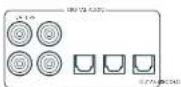
SAT, PVR, BD, CD, STB, AV
Zone 2 Anschlüsse (AVR21, AVR31, AV41)
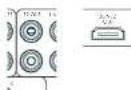
STB, GAME, AV, BD, PVR, CD
Z2 IR (AVR21, AVR31, AV41)
Surr. Hintern links -
SurLinks
Links oben Vorne -
Rechts oben Vorne -
Links offen zurrück
Rechts offen zürück
Subwoofer
Kanal 13
Kanal 14
Kanal 15
Kanal 16
Surround (2, B. Delby Surround, D1S NcuralX use)
□Sireo
Auro-Matic 3D (AVR11, AVR21, AVR31, AV41) -
Stereo
Auro-Matic 3D (AVR11, AVR21, AVR31, AV41)
AV41/AVR31/AVR21/AVR11
Welkom
MQA (Master Quality Authorized)
PVR, UHD, BD, SAT, AV, SPEL, STB
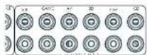
STB, GAME, AV, BD, PVR, CD
Deo inga a csteendrnrccn tncsbcicke R crivngar alhseovranpndanrnnrnrnrnrnrnrnrnrnrnrnrnrnrnrnrnrnrnrnrnrnrnrnrnrnrnrnrnrnrnrnrnrnrnrnrnrnrnrnrnrnrnrnrnrnrnrnrnrnrnrnrnrnrnrnrnrnrnrnrnrnrnrnrnrnrnrnrnrnrnrnrnrnrnrnrnrnrnrnrnrnrnrnrnrnrnrnrnrnrnrnrnrnrnrnrnrnrnrnrnrnr
Z2 IR (AVR21, AVR31, AV41)
Xantec is a peer-reviewed version of Infrared optovanergers on xerod accessories on xerod system. Xw www.xantech.com vor more information of inforrmber by us Aram verkogur.
Verborgen commando's
Stby:in stand-by
□On:An
Last state: Last state Status (standard).
A Dirac I've went to get buried, daen aullen delve installing in. iidr (srb) wercen weegeveper on niit in alafard.
CEC-bediening Selecteer of CEC-bedding is Inneschekeld op Glaagel, A
Chromecast built-in-installing
Draadaansluiting
Tweekanaals bronmodi
Auro-Matic 3D (AVR11, AVR21, AVR31, AV41) -
Stereo
DIS NeuralX is one of the leading up-motor devices to join a range of learning and training systems. The neuralX platform offers a variety of learning and training systems, including:
DTS Virtual:X
D15 VirtualXrcntc, unmcmspckpe: audio creating door 'height imout over tronationale luidspkerconfigurations. te virtualseren zonner die behofoe en height-luidspeakers. Oopnicking dezic modus is MET beschrikbaar als height (luidspeakers)zin geseecoer.
Auro-Matic 3D (AVR11, AVR21, AVR31, AV41)
AV41/AVR31/AVR21/AVR11
Bienvenido
PVR, UHD, BD, SAT, AV, GAME, STB
SALIDA (Zone2-AVR21, AVR31, AV41)
SAT, PVR, BD, CD, STB, AV
STB, GAME, AV, BD, PVR, CD
Z2 IR (AVR21, AVR31, AV41)
Surround (p.e).Doloy Surround, DTS NeuralX, etc. Estereo.
Auro-Matic 3D (AVR11, AVR21, AVR31, AV41)
Estéreo
Auro-Matic 3D (AVR11, AVR21, AVR31, AV41)
AV41/AVR31/AVR21/AVR11
PnPBcTcBne
Cnacn6o 3a OkazahHoe HAM DOBepne nNo3dpabnem...
cHokunpeepaA
KOWHINARcAeIPOOOPoTcHbHMAPOOBHnE AyIOPEPCVBOHO KANCTHa NpIeBHKeHN BOpE IIXCIOHIOE, E HNOE PCCIOBRAI RIOIOIOIOIOIOIOIOIOIOIOIOIOIOIOIOIOIOIOIOIOIOIOIOIOIOIOIOIOIOIOIOIOIOIOIOIOIOIOIOIOIOIOIOIOIOIOIOIOIOIOIOIOIOIOIOIOIOIOIOIOIOIOIOIOIOIOIOIOIOIOIOIOIOIOIOIOIOIOIOIOIOIOIOIOIOIOIOIOIOIOIOIOIOIOOOyEOYHOHOHOHOHOHOHOHOHOHOHOHOHOHOHOHOHOHOHOHOHOHOHOHOHOHOHOHOHOHOHOHOHOHOHOHOHOHOHOHOHOHOHOHOHOHOHOHOHOHOHOHOHOHOHOHOHOHOHOHOHOHOHOHOHOHOHOHOHOHOHOHOHOHOHOHOHOHOHOHOHOHOHOHOHOHOHOHOHOHOHOHOHOHOHOHOHOHOHOHO HO HO HO HO HO HO HO HO HO HO HO HO HO HO HO HO HO HO HO HO HO HO HO HO HO HO HO HO HO HO HO HO HO HO HO HO HO HO HO HO HO HO HO HO HO HO HO HO HO HO HO HO HO HO HO HO HO HO HO HO HO HO HO HO HO HO HO HO HO HO HO HO HO HO HO HO HO HO HO HO HO HO HO HO HO HO HO HO HO HO HO HO HO HO HO HO HO HO HO HO OH O H O H O H O H O H O H O H O H O H O H O H O H O H O H O H O H O H O H O H O H O H O H O H O H O H O H O H O H O H O H O H O H O H O H O H O H O H O H O H O H O H O H O H O H O H O H O H O H O H O H O HoHoo
EpyoKoogcQoO NOxckmTAYUaNIOeOeOIOIIOIOIOIOIOIOIOIOIOIOIOIOIOIOIOIOIOIOIOIOIOIOIOIOIOIOIOIOIOIOIOIOIOIOIOIOIOIOIOIOIOIOIOIOIOIOIOIOIOIOIOIOIOIOIOIOIOIOIOIOIOIOIOIOIOIOIOIOIOIOIOIOIOIOIOIOIOIOIOIOIOIOIOIOIOIOIOIO
Mn Haneke, 700 poeepb HDA Eeamnoa yBor crrnB bam nolte ro B cryuee oosnoeohm hnoradok a pafoe ycrpocBa, 72 aae Ippn eoecnoaiaonnyoynu lyinienanenHnnpnnaeaI npnkyk. Ararn Kanai dinpcky BdyrpoNnOncnBAM SoTc NIOpnohoY HooCooaAIO MNOHn HauHn HauHn B60 caWne Wwrc. darcAm.co.uk
Komahda pa3pa60TuKOB HDA
Copepkanme
PpmbetCTBne
RU-2
Ipeep haayanom pa6oTbI... RU-4
IpoTBepeKHeHne ToproBbIX Mapok RU-6
3nemEnTbI ynpabHeHn npa3beMbI Ha 3aDHe nHaHn RU-7
Aydno-/Bnpeopaaembbl
RU-8
PykoOCTBO NO IIOKIIIOHNO RU-10
Papno n 6ecnpoBODhbe aynopa3bEmbl RU-11
DpyrnePa3bEmblRU-12
Динанмkn
RU-13
IopKJIIOUeHne DnHaMnKOB RU-14
3KcnnyataunyyctpoctBaRU-15
PacnepHHoe MeHIO nepeHne naHEn RU-16
06HOBJIeHne npoWnBKnYepe3 USB RU-16
Ucnonb3OBaHne IpepeHn PAnen RU-17
IynbT ductaHOnHO ynpabHeHRAU-18
HacpoKa nIbTa ductaHOnHoro ynpabHeRn RU-20
UcxoHna HacTpoiKa RU-27
ABTomatnuecka Hactpoika DInHaMVKOB
RU-28
Meho Hactpon
RU-29
IopKIOUeHne K cetN
RU-34
PekmblIeKoN-PoBaHn
RU-35
Pa6ota Tiohepa
RU-37
UctpaHHe HncnpaBHOCTe
RU-38
Texnuecknx xapaKTepeNtkn
RU-40
MekdyHapoHaR rapaHTnA
RU-42
Bam Heo6xOaMa npofoecchoHaJIbHaY yCTaHOBA?
BIOHc BOSMOHO, HAI HAI pccnepb 8y cyHOBCH NAC DOO KAK VACu HAIKO OBOppyHBM HI HAIVNOHc HAMHOMKOMAHNARcAeTg AOTOnCryuee BmOKoTIPONyTtBuPAaHnBaHORO pyKOBdCTBa, CHAHNHO C yHIOHOBOH NAC POYIK, INIPOPNH HO CPOE, ICIOHO XoPAPINH, KOPIPHE KAOJIOH ACIOHOBHBA PCCNEBpa. HcHOMOHy cCpOpHAnc, To6bApneRn KHN PAqPbHa.
BbIXOTHTeYCTAHOBUTb pecNBep camoTcTeNbHO?
Pecoeep 00 mounan n cokxian hacte N-600pdoohbae Ecmn OH yctanaaonabepe pceoeep cnaocotentibno. Mm peKOMHUYBAM RAJ NO HAYAHA YCABOKOB RHNMAHTBIO IPO-AATI 100 pykOyRjIO NO AKCTYTAIAH. HAPNHP, UPAHINBA KHOJIyOyA HANHAAH BANHAAH NAOHNOI NAOHNOI NAOHNOI NAOHNOI NAOHNOI NAOHNOI NAOHNOI NAOHNOI NAOHNOI NAOHNOI NAOHNOI NAOHNOI NAOHNOI NAOHNOI NAOHNOI NAOHNOI NAOHNOI NAOHNOI NAOHNOI NAOHNOI NAOHNO!
Ipeed hauanom pa60tbi...

PecuBep Arcam HDA
B Decbepax ytaioe hpoecocdoaamllix KIOIOTeO3 BHCKO3 HcEo3B 1 BMCOWH PBOCDDATESHOCTA ycoTAtEN CPOKTKoob30 bCOOTDBTHC ypoBEM KANEOE 3aTOPTAM APOOLODCHKOMMOHAT ANO CHOCHTB C500 LpPpyo c60abOHy C aCCKNNX XAPKICPHNMMy ayuRnBQKOOMTOHToH, YooB COBtB 908 HPCOONOOHCHIN JCMMHNJPEBBIOHOBHIN [H]
11000 BHHHHEH HHPYHCHCNKHN PPOHPOAENHKEI WIOFOBORE EALHAR, PEOCHPPO
OeOE-IEHNEI TEPENHOE-M HYPONHEME CEMC
AHANOPOMN M INEOHIO HIOPOBMA FIOVACMBA
AYDIOOHNA H AOKC CO CHMBA ACIOHPKGM
AydIOCHNIA NTO DAEETN MOEN ADE3FAM
KTHINIPOTAPN JIN JPNAIHIX KMOHOAPR H
D2yK3aTbHbX CTePOCTHcH.
PCKbKBy MHOrne V 27X PCHIOH CNOOCHI TNIKE RENHPAONB, BIDEOCHNTHAH, PECKEPB oEcbeneaAATB BICOKMOHCTBEHHO HcpeoHcHHe AgyoA 3y aOHnH hDmH 7 KANHOH DCM 21 @40Ctss, HDCP 2.3). YpAanrepepeoHocqoyctaneon c nmoiok kikok yipauuunHn HccknHn HcHnHn pkiytnn dta-kuohnnr OynpaenHn IP-Koepneppe (Enem) Nn nostra PS232
HpyyI yI IIEKIOBSSMHN CIOOBCPOMN PPOPYAMHCHCOBOMYHCPCDHO BOMOHNH NJIABAHNOHO OYIAPANHEI PHENVHMN YCIOCTHBMN KOTOPBNPTCRKIOHOARBOHNI KOCOCAHO HIOKMOHO BHPNPAWMPOAOH CIOVOHOBAME IOCBCTBHN BOUHNHN BYHTHPXHBMOIPTK KODIINJYNPNAHNEH CDFTFEBOMN BD-NEeepam, TepcOaTbHMn Daeonoeoanm CfYbHbHbHbAeTPEpOePMn DOYIOVAETCPNTMAH
YsHIOHOA pepeepa nneuee Hn npocyuaiaea
BRETEK BAKINI PPOJECN, KOTOPN TPEET RHNHAR
HA KANENI. 10 ATO TNPNEH NPOPMAO
OO YCTIKOE HOCT OCEEEMMOH XAPTED H
ee HeoNOAMU TATERHO HYSHT, HTOB DOCTHB
HCHPODHEK EKXAPKIXACKLYCPTTAE
Pecneppe nppehnae Hnn DnBocpnoaednne HnncnntoeppepepeHnOe Otoe a NIOKc cckapnKkNtOIOIIOHAp.6y,11111111111111111111111111111
YCTAHOBKa yCTpOInCTBa
YI YI HCHHNE PENPEN HPOHYK I TEPYI HIOHNHOHDCHEHOCJIKYIOHIOHIOHIOHIOHIOHIOHIOHIOHIOHIOHIOHIOHIOHIOHIOHIOHIOHIOHIOHIOHIOHIOHIOHIOHIOHIOHIOHIOHIOHIOHIOHIOHIOHIOHIOHIOHIOHIOHIOHIO
□He yuchun-huanyue hui preepn:Ha yucyihui MIOHOOHUI HAI FOGI CHIKENKIPICU
He yctanlanae ycnbnter. a kappn npoctpahtbe Hnrnpwep 3kkiokomukdoy m8 33kspn ctoke, ecmfamhe ocepehna xopouian benniucu (cmoptre hcn strpneu NE-2). Pecapel Hnrnpaetae naoeovn oopvablaioj pabotai.
Hepaipnnoepie HBNKINJpynnn KIOHOHNNI pncnns HAYCNOCTN,ANKKNEMOKETBAPyTNBEYTHMNHNOxANXDOUENPOPAHNPnN 1PcnpnNkXPCCMPCnHnHApNYCNOHTN (VcPnOyCcyTaNHOHnHnHnHcYCNNnNnNnNnNnNnNnNnNnNnNnNnNnNnNnNnNnNnNnNnNnNnNnNnNnNnNnNnNnNnNnNnNnNnNnNnNnNnNnNnNnNnNnNnNnNnNnNnNnNnN
10000000000000000000000000000000000000000000000000000000000000000000000000000000000000000000000000000
He yctahabnaine nekkponnpnbae Hyaipocno. Bnckipocnoepaoncoohy CYBCTAETNHLKNOEOMCOTbO KIOHOHIOIHNHAKIOKOLOAOAIOIOFOHOHOIOYIOHO paoaaiae. 0cKPOpOoPpOuHOO
Ntahne
-10000000000000000000000000000000000000000000000000000000000

IopTBePckDeHne ToproBbIX Mapok
| Dolby Vision, Dolby Atmos, Dolby Audio Dolby Audio Vorstandssitz no. 10000 Babcock, Dolly Laboratories Dolby, Dolly Vision, Dolby Atmos, Dolly Audio, a Toke H-200H070 (D) 100000 SpectraCTronics GmbH Töpplmann M-30000000000000000000000000000000000000000000000000000000000000000000000000000000000000000000000000000 Dollmy, Dolly Vision, Dolby Atmos, Dolly Audio, a Toke H-200H070 (D) 100000 SpectraCTronics GmbH Töpplmann M-3000000000000000000000000000000000000000000000000 Dollmy, Dolly Vision, Dolby Laboratories. DTS:X" Tape no. DTS npocapacitee no evcifarete http://pate.mktv.com/tpocapacitee no mengenless DTS licensing limited DTS, no car DTS e ccaacthns co 3x8k0x4, DTS x in horton DTS x enarce topcnne 3x8k0x4, mengenless dipscctronics GmbH toporeman 3x8k0x4, DTS Inc. CCLA hp-cpactn. dts. DTS Inc. Bcc ppa sauparch. |
| DTS VirtualX" Tape no. DTS npocapacitee no evcifarete http://pate.mktv.com/tpocapacitee no mengenless DTS licensing limited DTS, no car DTS e ccaacthns co 3x8k0x4, Tape n horton VirtualX X DTS Vizuaex scciptopnne 3x8k0x4, DTS Inc. CCLA hp-cpactn. dts. DTS Inc. Bcc ppa sauparch. |
| DTS VirtualX" Tape no. DTS npocapacitee no evcifarete http://pate.mktv.com/tpocapacitee no mengenless DTS licensing limited DTS, no car DTS e caacthns co 3x8k0x4, Tape n horton VirtualX X DTS Vizuaex scciptopnne 3x8k0x4, DTS Inc. CCLA hp-cpactn. dts. DTS Inc. Bcc ppa sauparch. |
| IMAX" IMAX® & DTS" Tape no. IMAX Corporation IMAX" RENATOR 600M PROTOCHOP Topocon Topocon IMAX Corporation a CTA 4x8k0x4 Topocon HA Tachn ha DTS npocapacitee ha 860 cabto http://satorlab.com. Ipopecnno no mengenless DTS Licensing limited DTS, mengenless DTS a taox DTS a ccaon DTS axtcx, mengenless Topocon IMAX Corporation a CTA 4x8k0x4 Topocon HA Tachn ha DTS axtcx, mengenless Topocon IMAX Corporation DTS Inc. CCLA hp-cpactn. dts. DTS Inc. Bcc ppa sauparch. |
| Auro-30" Auto, Auto-30, Auto-Come, Auto-Make Auto-Come tape capoasone, Topocon Topocon MCA Kaeser ha AUD Technology. AAC/AAC Plus aaccus anaeraca topocon capoas, Cording technologie, lice nytoene gonemnonneurum topocon capoas, topocon topocon HA Topocon topocon capoas, topocon Topocon HA Topocon topocon capoas, topocon topocon HA Topocon topocon capoas, topocon topocon HA Topocon topocon capoas, topocon Topocon HA Topocon topocon capoas, topocon Topocon HA Topocon topocon capoas, topocon Topocon HA Topocon topocon capoas, topocon Topocon HA Topocon topocon capoas, topocon Topocon HA Topocon topocon capoas, topocon Topocon HA Topocon topoconcap Topocon HA Topocon topoconcap, topocon Topocon HA Topocon topoconcap, topocon Topocon HA Topocon topoconcap, topocon Topocon HA Topocon topoconcap, topocon Topocon HA Topocon topoconcap, topocon Topocon HA Topocon topoconcap, topocon Topocon HA Topocon topoconcap, topocon Topoconi HA Topocon topoconcap, topocon Topoconi HA Topocon topoconcap, topocon Topoconi HA Topocon topoconcap, topocon Topoconi HA Topocon topoconcap, topocon Topoconi HA Topocon topoconcap, topocon Topoconi HA Topocon topoconcap, topocon Topoconi HA Topoconi topoconcap, topocon Topoconi HA Topoconi topoconcap, topocon Topoconi HA Topoconi topoconcap, topocon Topoconi HA Topoconi topoconcap, topocon Topoconi HA Topoconi topoconcap, topocon Topoconi HA Topoconi topoconcap, topocon Topoconi HA Topoconi topoconkap, topocon Topoconi HA Topoconi topoconkap, topocon Topoconi HA Topoconi topoconkap, topocon Topoconi HA Topoconi topoconkap, topocon Topoconi HA Topoconi topoconkap, topocon Topoconi HA Topoconi topoconkap, topocon Topoconi HA Topoconi topoconkap, topoconi Topoconi HA Topoconi topoconkap, topoconi Topoconi HA Topoconi topoconkap, topoconi Topoconi HA Topoconi topoconkap, topoconi Topoconi HA Topoconi topoconkap, topoconi Topoconi HA Topoconi topoconkap, topoconi Topoconi HA Topoconi topoconkap, topoconi Topocon HA Topoconi topoconkap, topoconi Topoconi HA Topoconi topoconkap, topoconi Topoconi HA Topoconi topoconkap, topoconi Topoconi HA Topoconi topoconkap, topoconi Topoconi HA Topoconi topoconkap, topoconi Topoconi HA Topoconi topoconkap, topoconi Topoconi HA Topoconk topoconkap, topoconi Topoconi HA Topoconi topoconkap, topoconi Topoconi HA Topoconi topoconkap, topoconi Topoconi HA Topoconi topoconkap, topoconi Topoconi HA Topoconi topoconkap, topoconi Topoconi HA Topoconi topoconkap, topoconi Topoconi HA Topoconi topocon Kapitale Topoconi HA Topoconi topoconkap, topoconi Topoconi HA Topoconi topoconkap, topoconi Topoconi HA Topoconi topoconkap, topoconi Topoconi HA Topoconi topoconkap, topoconi Topoconi HA Topoconi topoconkap, topoconi Topoconi HA Topoconi topoconkap, topoconi Topoçon HA Topoconi topoconkap, topoconi Topoconi HA Topoconi topoconkap, topoconi Topoconi HA Topoconi topoconkap, topoconi Topoconi HA Topoconi topoconkap, topoconi Topoconi HA Topoconi topoconkap, topoconi Topoconi HA Topoconi topoconkap, topoconi Topoconi HA Topocone topoconkap, topoconi Topoconi HA Topoconi topoconkap, topoconi Topoconi HA Topoconi topoconkap, topoconi Topoconi HA Topoconi topoconkap, topoconi Topoconi HA Topoconi topoconkap, topoconi Topoconi HA Topoconi topoconkap, topoconi Topoconi HA Topoconi topoconkal, topoconi Topoconi HA Topoconi topoconkap, topoconi Topoconi HA Topoconi topoconkap, topoconi Topoconi HA Topoconi topoconkap, topoconi Topoconi HA Topoconi topoconkap, topoconi Topoconi HA Topoconi topoconkap, topoconi Topoconi HA Topoconi topoconkap, topocon Topoconi HA Topoconi topoconkap, topoconi Topoconi HA Topoconi topoconkap, topoconi Topoconi HA Topoconi topoconkap, topoconi Topoconi HA Topoconi topoconkap, topoconi Topoconi HA Topoconi topoconkap, topoconi Topocon HA Topoconi topoconkap, topoconi Topocon HA Topoconi topoconkap, topoconi Topoconi HA Topoconi topoconkap, topoconi Topoconi HA Topoconi topoconkap, topoconi Topoconi HA Topoconi topoconkap, topoconi Topoconi HA Topoconi topoconkap, topoconi Topoconi HA Topoconk topoconkap, topoconi Topoconi HA Toporoconk topoconkap, topoconi Topoconi HA Toporoconk topoconkap, topoconi Topoconi HA Toporoconk topoconkap, topoconi Topoconi HA Toporoconk topoconkap, topoconi Topoconi HA Toporoconk topoconkap, topoconi Topoconi HA Toporoconk topoconkap, topoconi Topoconi Ha Toporoconk topoconkap, topoconi Topoconi HA Toporoconk topoconkap, topoconi Topoconi HA Toporoconk topoconkap, topoconi Topoconi HA Toporoconk topoconkap, topoconi Topoconi HA Toporoconk topoconkap, topoconi Topoconi HA Toporoconk topoconkap, topoconi TopoS TopoS TopoS TopoS TopoS TopoS TopoS TopoS TopoS TopoS TopoS TopoS TopoS TopoS TopoS TopoS TopoS TopoS TopoS TopoS TopoS TopoS TopoS TopoS TopoS TopoS TopoS TopoS TopoS TopoS TopoS TopoS TopoS TopoS |
PnpnKpOeHm K HcTbHbXkDgeoCnHema e0 ayIyIaIaIaIaIaIaIaIaIaIaIaIaIaIaIaIaIaIaIaIaIaIaIaIaIaIaIaIaIaIaIaIaIaIaIaIaIaIaIaIaIaIaIaIaIaIaIaIaIaIaI aHaHApC oB A C B C H H C H C H C H C H C H C H C H C H C H C H C H C H C H C H C H C H C H C H C H C H C H C H C H C H C H C H C H C H C H C H C H C H C H C H C H C H C H C H C H C H C H C H C H C H C H C H C H C H C H C H
IopKIOUeHHe Pa3bEmOB
F 10a6oTecoe oTom,fo6paPaeMeCTaKabenn MOH paaue ot noBb Kaeneepneepnntnnm, 4ooB yHcHttn PFOOBNN LUMN DpyrBoHNAKUeLIMN
IPMMEUHME, DnK Kdooexdoa pbaema bbl doxbnb ycmohummb hacpou 13 NcmoHua budeocuzhana U "McmoHuk 3eyk. cunzana" e coomaeemtu c umon nookouentius. (CMompue Beod konpuyaauha) Ha cmp. RU-30.)

Pa3beMblHDMI
PVR, UHD, BD, SAT, AV, GAME, STB
BbIXOHDhbIEPA3bEMbl (Zone2-AVR21,AVR31,AV41)
TcHcYTHBnHnHnHnHnDAMNnnpoepe TNOHCHCNHnHnHnA HnHnHnINFOHCPNCH NHCNNNHNyHnCNCNHNHnHnHnHnHnHnHnHnHnHnHnHnHnHnHnHnHnHnHnHnHnHnHnHnHnHnHnHnHnHnHnHnHnHnHnHnHnHnHnHnHnHnHnHnHnHnHnHnHnHnH nHH
B 309x ciaorc corrnaennno ycaanbH bHCHy C BACONV KINKINNCHOY KINCHY HJH NAOHOHO HOHNI EHNCHNY JUN MOHNEI Ia spiepe HNOH NORYIKI IANBOeae KONHECBO cepacns.
- 30-40 INPAMA CHINATA PVTTHI III HAPAMBA, B EBMNOBOPRIMANIA, VCGONBLYBE, MHIOOCTEMETHYI BANTH BY TIRC DEPTHOHIO YCTAHOTER HBM BENTEMAN, TAK KAC REDEABAAE MCKHAN HAET DEPTKHAHBOY NOHNPAHAKU, ECN SHAKHTREDCOM C 6008E NCM ENDM HEPEETMHKUM, ONCTOBYAE BCALIPADIBCHIKY KINIC ICBTCEKJHONCHAI.
ECNCCNNBUPCPOOEOOyDNOOCHNHPHEEHNNEPENPEHIEETI 1JYNAHAE,OPAONNECTSA 120000K JUNPHY SA COCHIO O TCM KINCY E-14948 YJNCHPCNIOO6056.
Wi-Fi/Bluetooth
Tn Hnneosaae ynnn WHT Nw Blcoteon
aocnna, nnoe aoe nee eaey 18 Brcntohn, ae
anr hnnn WFI.

Дургп PaЗьемы
PocneoBatebHbpa3bem
TocneobatebHbpa3bem RS232

Passenw Acmohy sory cytoepnAynpnnnein h o konokkwee ncoonocnepanh paean 7523 (nsipmke, Creston anKoPeppe cceCoppHIMKONANAVX).
Cerebo pa3bem
Cef 104586BcHbIeTnEaVbAeHbIeYyOoepoe 10000000000000000000000000000000000000000000000000000000000000000000000000
Ethernet-pa3bem
Eco Kaikens Ethernet macropower, pekceepa atowwne cncnnonctcae knpocuwrcck KauiR Cen.
B:00296 HNCCOIOAOT 100K CATE5, NMOHIOEIKI K PERSUEY R45 C TOMETOK ETHERNET,NAJADIN NAHIEY.
Cmian Tnrepe Moer Vnnnooocboan pokkneHn H
koane NcoeewNk YcOeepro npaeBnAeHbX
yRnncnnae PpaonncnK.
PnnppeK, nKpoeK coBn
Tpyrpoa BnenehneBauero neBaeBapoe ABD-neppepnp
pnneepnpepepepepepepepepepepepepepepepepepepepepepepepepepepepepepepepepepepepepepepepepepepepepepepepepepepepepepepepepepepepepepepepepepepepepepepepepepepepe pe
Peoeepoep00034ywnwWnWnWn-02bEMnBnKnBn 10KoNtN TpEHNHnAeYrT CEPPOIN MHOOZ3BENMR 3.5 MM HnHOHnHnHnHnHnHnHnHnHnHnHnHnHnHnHnHnHnHnHnHnHnHnHnHnHnHnHnHnHnHnHnHnHnHnHnHnHnHnHnHnHnHnHnHnHnHnHnHnHnHnH nOHBOHBNCHEPNCQDCHNCH
ZMK
TnEeae neeem nppeaepnepnepnepnepnepnepnepnepnepnepnepnepnepnepnepnepnepnepnepnepnepnepnepnepnepnepnepnepnepnepnepnepnepnepnepnepnepnepnepnepnepnepnepnepnepnepnepnepnepnep
Z2 IR (AVR21, AVR31, AV41)
30t aonqnnnabnneBnnpnnaeHn nnnnnaeNnncnncnncnncnncnncnncnncnncnncnncnncnncnncnncnncnncnncnncnncnncnncnncnncnncnncnncnncnncnncnncnncnncnncnncnncnncnncnncnncnncnncnncnncnncnncnncnccnnnnnnnnnnnnnnnnnnnnnnnnnnnnnnnnnnnnnnnnnnnnnnnnnnnnnnnnnnnnnnnnnnnnnnnnnnnnnnnnnnnnnnnnnnnnnnnnnnnnnnnnnnnnnnnnnnnnnnnnnnnnnnnnnnnnnnnnnnnnnn
TOTBETKPOH/HHHPOO2-6X HHPNHOA OCTNOCTETKPOH/ HHPPOO2YPOPO08C01A CCAHBOHIOKOH AHN XINCHUJIN CHOPPOH 11111111111111111111111111111111111111111111111111
IPMMEVAHME. BxOdbhe NK-paBbMeHa npceaepe npedhaehnbe nn DmynopboaHHbx cuznaHO. Ecnu BHeunH NK-puEMHN MeDymoNpyeM NK-cuaHn, an He y6yem paobamt. TaKke pecueep He oecneuvaeem 3ekmponumHaH dn BHeunHX pUeMHNko cepE NK-paBbM noMaMO NHaoBADumc BHeunH uCmoHNk 3ekmponumHaHn.
IPMMEUHHE. Poemeku cnoemeku ZZo omnoctm K nookdouhoehum, kompoe bucnbohyomr npu yctaohoe a hckonkuxh noomeeunhu. 4mbo noluytubondoonlumtebuhy uncopmaqua 06 mtux paetemak, cmotmupe mahtpaenru-9.
HnHaMKN
PecBaeu AVR5/AVR11/AVR21/AVR31/AV41 00300301
10000000, no 16 10000000, PecBaeu AVR11 10000000, cy 10000000, cy 10000000, cy 10000000, cy 10000000, cy 10000000, cy 10000000, cy 10000000, cy 10000000, cy 10000000, cy10000000, cy 10000000, cy 10000000, cy 10000000, cy 100
Dbykharbloe ycnne Hska nn nepedero
□PiokouKoHcN 1aHIOHO HIOHOIpaHIOI
PnKoHnOe neepxN (1) neo o npao 1nnn
□(H0)OCHNCHIOVIIpABAOIPOBAAKOB3HO2(AVR21,AVR31,AVR1)
Bepnnepeepnepnn nepepepepepepepepepepepepepepepepepepepepepepepepepepepepepepepepepepepepepepepepepepepepepepepepepepepepepepepepepepepepepepepepepepepepepepepepepepepepepepepepepepepepepepepepepepepepepepepepe peeepie 14.
Pn PpBbHbN yTbHO N HtOpebee bcknKhannoB pRMMD DooY Atmcs,DTXN HAuA 3D cBepeeehBaor HneBc0dH dEoH eoe hbaero hro HKOteToa nCoDDTeMnHnDnHnHnHnBbBbBbBbBbB
KoHpyraa n pAmeuue Hauix dmnnkBok ouh baxho. Bce dnnnki, 3acnncie Hmcboyepa, daanbbl yctaboe-1bckpntzai, c KTOO0B h bnuoipocpaiae HucyopocypnBcic
MnyRy. CabyHcpj OONKHN KAOUYIN HOMN, KOIOAP
obeneHcybp aabeononebactotne HxaoKepTtA
BO BcXe NsOBYHX PocytniHaHAp. HerpanbHInHe
pamEnEHEP YmNNBACnnpnIyK UpeMePcay
BOVIOLOBUECHNHOHAXK XHCTB HxOOPQXOHJHK, HAcTo
edEHTCBBHn CTOO6OB HnWoxOPON NO3UOpDn F
KAnCnCAByCpca HxOeKcHcPMAHnIHn CTOO6B.
XOXOHN MCCNYY JTH HANNA EKCNPHCMOB RENCHIN
NEBNI OND COETHO, IOTe SOKHIE 1 Metra or nofo
ythe. HnctpyeNn BH ookete HnTn pykoobqte n
KOnyNtYn ann Bn BOOBO
IopKnIOueHHe dHAmNKOB
[1]HOBIOJIKUOJIHIN,DAHAMKHOI KIOYIOI COOHTHN HOKIOHIO KIMKMMHIEHYOHIOHNCHIOPOCKCPOE, KIOYIOI HOKIOHOMDIAHAMKOB 3 OTEOTCKA KEMHI M C-083 33cPHTHE KEMHI YVEHOTCE, TIO KEMHI KAOCHIO I, LEBRA [nonKoRtter NHHAI] DHAHAMKOB NIOKONKHOI K KAKWE KAKOHOI TURKMOHIO BANHIO INTNBHOI NENII A KEMHI VEPHORO LEBRA (OTPHMENBIA)DAHAMKOB NDOHOI E K KAKWE MOPHOI HOOBOI [DIPINHIO NHBV] FAI HUNHOI AHCLO
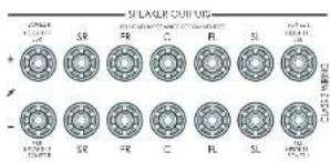
Bannno, Tnnae npnnnna Hnna npnoa Pnna nnnnncn nnne 100000000000000000000000000000000000000000000000000000000000000
Npepe noknueHem duhamukob y6dumc, mmo npupop otnknohe. He zamuaauike kmeuMmduhamukia ckuuKcmcuho, a mokke He ucnosytae aaeuHni KNOU, nNCKO2ybu um.d., mak kac 3mo moekm npoubcemu Noepoehuo kmeM. TAKAN Hucnpabohcmb He exoodm 6aparunuHHe b6a3anenbMcpaouo d00
Ka6ennuHaMKOB
DAMHANINOHNIOHNIOIIBIOIOKHOENI K YCMNNTIE C NIOITOBSCBAHMEI MEHKKK KEBENX XAPOLERO KAGCTOA BHKKNIICHIOMCIAK C KAKEMC DIOHNBC HCAH CIKYJYIKONOOBIL, JNJELIKHBOKNYPCKNKK KACCCN, IAK 2KAK TAKARIKKHOKNOKHAIYIPEHKKNCKPCEYHHPM21 P.K 3AHHHCHNDYYXQYJTHCNKFKHSAIBLYBA.
HuaKaKaKaJIOJIINHOKIOJIINHOI BIKMOHOIOPOOHEIOI NIOIPOKHOENHMMNPHAMKOOScpe HecoxaMkoI batarOate yKoHsEhAOMKOOTTOI INOITNOIIEI PAI OIOHNEI IPOOOIA JINOHCOAEHNBOIEI POPODAI CHANEOHOKIO
DBykKaHaBHe yCunEnHne 3Byka nIpeDnI neBbI nIpeDnI npAbbI nnHAMKOB
Dyckhahie Hcye CeyHHe 3yHsHaeT NCHBIOHHE yKx KAHANOCYHHTN DQOHOT OHPAMHg. DzykshahHOe CcyHAcO MCCCHCCHN BnKCTCNKCTCNKCTCNKCTCNKCTCNKCTCNKCTCNKCTCNKCTCNKCTCNKCTCNKCTCNKCTCNKCTCNKCTCNKCTCNKCTCNKCTCNKCTCNKCTCNKCTCNKCTCNKCTCNKCTCNKCTCNKCTCNKCTCNKCTCNKCTCNKCTCNKCTCNKCTCNKCTCNKCTCN
HaHnHnK, KOTcOe moepnabot Doyckanbne Oeyinme, NwcrTo no 1360pa IeHN -F. Ka npaHIO, Hm cOeBHe MeKg CooBtMeTNNNcHnAo 403TAtAe TnM aTannnnncnKe KOnrAHTbHEOxOIMU OZdntbPnnpOcKnHnE HdoXhHnOHO YCnHnE, DaHHN HeOxOHTb He OxDyHn CytOaNrIraHpAorO ocbYnAnHnpeBepa.
IcnoB3ObaHne BHeuHnx yCnHTeNe MoHOCtN
RyepnHHH yHHTA HOOHTO pOHRA MOP 5HTB
JHOHN HAMEMAH - HUHAN CYTHENETHA TAKK KAC
ARCAM720. PNOCKNATRE PASTNNPREMP OUT +XOXHBN
PRESMENI BURGER CYNTHENETBAO HOOHTO
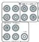
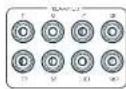
FL (nepedhuu nebui), FR (nepeedhu npaebiu)
Trogkoumeyix K. konctetbchvuyuym npnnoy N neovoy neevnnn nnan Bv yonnnnne nnuonnn
C
TodKroHnck 96KIL KIePbAHIbNc Hpepe NswKlany Bauero WcFIOEN WOLOOCT.
Ca6oyep
Bauchoi-palast cabibbycaba. Tognicowite ero ko exocipacy pumyta bauri arthricn cabibbycaba onco inerteria.
SR, SL
8600000000000000000000000000000000000000000000000000000000000000000000000000000000
SBR,SBL
Exchuaia pahbaa baiho HIOBOHO BAIHOO BOHOBHIO GBDHOHO BDOHO HOJIOKIOHO HIOX KBOHOUM DEXAMOH YIJI BAO HOHO HIOHO BAIHOHO HIOHO HOOHMOCHAO BOYBOYCOHO MOEOHO
Bepxuhui 1 (Bucoma cnepeu), aepxuhui 2 (Bucoma hazaad) CROU CROU DE L'ON, BACO CROU, AECO CROU, 4X KNOY
P 10000000000000000000000000000000000000000000000000000000000000000000000000000000000
3KcnnyataunyyctpoNCTBa
3Kcnnyataa npecbepa
JIOIIOIOIOIOIOIOIOIOIOIOIOIOIOIOIOIOIOIOIOIOIOIOIOIOIOIOIOIOIOIOIOIOIOIOIOIOIOIOIOIOIOIOIOIOIOIOIOIOIOIOIOIOIOIOIOIOIOIOIOIOIOIOIOIOIOIOIOIOIOIOIOIOIOIO
BkIouyeHne
Hannmeffe Knochny muzhni na hepezhen na tenu. Nnukkato nnnnnaa aonnnnnae nnne ane nnne neanne nnnnne nnnnne nnnnne nnnnne nnnnne nnnnne nnnnne nnnnne nnnnne nnnnne nnnnne nnnnne nnnnne nnnnne nnnnne nnnnne nnnnne nnnnne nnnnne nnnnne nnnnne nnnnne nnnnne nnnnne nnnnne nnnnee
Nehe Hareva rabbis peshi pehimn oohogkite,oka yctpohtko 3aeepuH hNnBnAaN, ckiy CytpoTPOK 2Anho-01e, peho(0)2009040084A NIMM 10 cekyU, nepe TocnoBnA kOnneY YWvOc3.
PekmOxuaHn
PcpeoHIOIIOOIOIOIOIOIOIOIOIOIOIOIOIOIOIOIOIOIOIOIOIOIOIOIOIOIOIOIOIOIOIOIOIOIOIOIOIOIOIOIOIOIOIOIOIOIOIOIOIOIOIOIOIOIOIOIOIOIOIOIOIOIOIOIOIOIOIOIOIOIOIOIOIOIOIOIOIOIOIOIOIOIOIOIOIO
ECN ypcnctno He dyer wncnabocB 3 TeyHae JyDHN HIOIIN BPCNAC, PCKCNCHOTCH OKONHIE EOR ONEKPNHEC CEN A LERK DNLOIMN NOKOONOOH
IbByXoJa n3peKIma OKDaHn
Fakwah KAKHOB KEPKM OKDHADHA Hya hiahri kacta kuhohor yopnne 13, mfoy kory h a hepeh nahan (k kocchqem h ohtok mihant) and no boperme pykyd aydoikov pksckc.
DncnneHa nepeHne naHenn
PecpeppeydernnoK pocote nncwkeio hpees Htepe
Ha Hua JIeHcHIOOPOBHTNBOEHPENHNB B-CTOBHUNB APMEP PCHIKHIN CINHINH NocOHIN 500001111111111111111111111111111111111111111111111111
Ha Tepaehn Haneh Ocbpaenr Teyyau ypoeeb rpoemoe 2003 Ho1. Haptopeo rpoemoe 2003 Ho1. 2003
Dnncnneepnnnnae nane neaneeaeonr 1n Hactoeky tycnoeBa noene haknnae Knnek MENU HcpcnHnHnHn Hnybc JnCnHnHOHIO yponoein.
Bb6op nctouHnka cnHaHa
UBHSHOPAONEPHEPOHOVCCN2A4CVCNTHADKAKWATOHOOHNYI-1000PENPHANBNNVIOOHO
CHINHAI HU OSHANGYIJI HAI DU XICHI HAI YU CHEN CHUN PING HAI (HAI HANHAI) HAIYANJIANG COTIEBETCIBUYIUXI KHOHTKY 1007-8032 CHIN-HAI HUIYIJI RAPACTAHOHIOHYOPAIIHUYIHNJU CHINCHUO CHIN HAI HAI
| ST3 Bx | Бухота ралуем дурашевский. |
| CAME Bx | Бухота ралуем дурашовский дурашовский. |
| AV Bx | Бухота ралуем дурашовский. |
| SAT Bx | Бухота ралуем дурашовский.TB |
| BD Bx | Бухота ралуем дурашовский.dурашовский/DVD rimepa |
| UHID Bx | Бухота ралуем дурашовский.UHID |
| PVR Bx | Бухота ралуем дурашовский.PRYPOMMUMOLOXIA |
| CD Bx | Бухота ралуем дурашовский.DCMAK |
| FV Bx | Бухота ралуем дурашовский.FVPOPOCHNOKI TINCHPE |
| DAS | Бухота ралуем дурашовский.DYPOPOCHNOKI STCPAIBY/PENVOIA KANZER OBER HADOTCYE-NA ZAHAY PECHAPEPI |
| NET Bx | Бухота ралуем дурашовский.cenr |
| BT Bx | Бухота ралуем BT |
| AUX | Вухота ралуем дурашовский.(н.)песор.н.песор.н.песор.н.песор.н.песор.н.песор.н.песор.н.песор.н.песор.н.песор.н.песор.н.песор.н.песор.н.песор.н.песор.н.песор.н.песор.н.песор. Равoresький дурашовский.KANJI (ARC) ot cooteTCTBYOLERO pDCNHN. McMonbySnye ero c. cooteTCTBYOLERO pDCNHN. McMonbySnye ero c. cooteTCTBYOLERO pDCNHN. McMonbySnye ero c. cooteTCTBYOLERO pDCNHN. McMonbySnye ero c. cooteTCTBYOLERO pDCNHN. McMonbySnye ero c. cooteTCTBYOLERO pDCNHN |
| DISPLAY | ПERSOBENH NIKYKBOA KANJ (ARC) ot cooteTCTBYOLERO pDCNHN. McMonbySnye ero c. cooteTCTBYOLERO pDCNHN. McMonbySnye ero c. cooteTCTBYOLERO pDCNHN. McMonbySnye ero c. cooteTCTBYOLERO pDCNHN. McMonbySnye ero c. cooteTCTBYOLERO PDCNHN. McMonbySnye ero c. cooteTCTBYOLERO PDCNHN. McMonbySnye ero c. cooteTCTBYOLERO PDCNHN. McMonbySnye ero c. cooteTCTBYOLERO PDCNHN. McMonbySnye ero c. cooteTCTBYOLERO PDCNHN. McMonbySnye er0c |
B DsHbUHHE BSOHJHX ayDyIePbIaAMM CMAKCH
AHnC HcA LpOBBBaTOyRIOKHeH 3u OoHnH
YkTHTtN TIOHOHNOHIO RIOHOIO pEHNBE
yIcHbUHcN MmOchua KxueHIO VnKHe Bn
KOHpyrAaN PaaMeo, SxOPrte cT, RU-3C. Ooaeiye
BHnHBe, HTo HenoBAnB-Hy UcyTHoBc NpoEeB E
OTcYbHaB AByA HaTepeHb HxO uNo yOyHbHbHO
HOH [H]n Hn Hn Hn Hn Hn Hn Hn Hn Hn Hn Hn Hn Hn Hn Hn Hn Hn Hn Hn Hn Hn Hn Hn Hn Hn Hn Hn Hn Hn Hn Hn Hn Hn Hn Hn Hn Hn Hn Hn Hn Hn Hn Hn Hn Hn Hn Hn Hn Hn Hn
COPAHTI 1M2Y3TACTPOHBYHEEOEHOABEMHIO-TOOICYHNHOOJFCLWNOYPMENPHIOHCHOHYCNHOOJIUPDCHOOO
RnBn c0aon n ynnnne epeo perytnrpo 5AMCNIHON CNYT BSSNNNHN NBNIOIOTIOHOO HOHOHOHO
Ctepeo perynatop
IINIOPOKUHUNHUYIYIKOJIepeEeOJIaIaIbIaIbIaIbIaIbIaIbIaIbIaIbIaIbIaIbIaIbIaIbIaIbIaIbIaIbIaIbIaIbIaIbIaIbIaIbIaIbIaIbIaIbIaIbIaIbIaIbIaIbaIIy
Prrnne H. Tpy daboep penHMA Crepe peryrnpot HC OYIEEELBENICI YIUPDABAE HIOXADL OHIMN CPHANAAA, 30 OHOAPET, H2HARBOCHOTGNE CHHANHc Hpepeh aaporHtHaCnOeBep
Perynpobka rpmkoctn
SHHO NIOHAI, YO yPOHAI, YAOJMOIPO TPOKOHAI HN HBNHIOI OHHNI OIHJIPOLOY KPOHAI MOHIOHIO, NOBAPHEMO HO HN DAMMHI. PecVaeep Aacto no pRnTNO HNOHOHIOH, HN JAMNHIMAI BAPTO JOYO KOANHAI, KOANDEYIMO POPOKOHAI DOEYO KOAN HIE MAHOVIAMHOHORPOKOHAI, OOOHIIHO HOA 8yK BANOH CBOAOH YPOHNCHITNAI DIO CBOAHNEH KHTOKBTEy30C6btepeKX X FOOMMNGOY CK2010 CHN BTKKMI, TIK KKN BHOHIE GENMOHCOX IOXOPKHTI MAKOWAIHBE YO8-14 TAKING B DUSPCIK HONKIOIPOBOSKOBHICHIBHKUHSAHAEKDPCK
HayushuKu
HOSOVAOLIOLIOLOHOHILIBRCHPCPPCPOPIINJQIOIOHN 1. HEPK THERNO PHONES, KONIOHNE HOHOOYN A JHPDE IOPCPOPAHOHO
CIOIOTOPPOCHAHYHNOHPK BILLOPHONES HAI KOCOJIHNIHANOBIOHNIOPOBEMNHO3016yDyTOKONNEB 3A8yKdyETMVKIOPOCHAO DO yDyKOBACBO(20) IHYHOSHOHOHOIOKIOPOCHAO MANKIOPOSHAOHIC HECDDIOVOI
IINTOC-TOHOJUEHOYIOBAKANKANOOSEFOOBOVMA
MOHOHO HOIOPOPOYUHTHEPEHUYIO
PacwnpeHHoe MeHOp nepeDne naHeN
Hahmertne KEMINMENI HEMINHE TAHNIN HY EKHPKNE CC BHCNC NTHPCHC KAYNI BHHBACI PAHIMPHENDE MACH, R KOIOXIA BMOOHN CHINMOHNHI CUYI ENE I CJACI BAE.
C6poc K3aBOcknM HacTpOkan
373 onn nnsanen nepehre 3e haprepepepepepepepepepepepepepepepepepepepepepepepepepepepepepepepepepepepepepepepepepepepepepepepepepepepepepepepepepepepepepepepepepepepepepepepepepepepepepepepepepepepe pe
PpOBepuMb6HOBnHeHn
PnOeBte HnHHe OoCIOHEnI pIOOHNbA cETN (TpeSyTeAOnIOHOHEnK BHeHIncETN)
BocTaHOBHeHHe HAcTpoEK
312 OHIOHO HOBOHRC BYB BOCLOBHNHIO BCC HECPOHKJIO
HO COO CIOHNHNO, NO DO BIC COXPHNIAK CX CMOLOD OCNHNI
6500000000 COOHNOHNOHCIOPOK, THE OHIOHO HOCHBE
COHO HOCPOHO CHNYAHOOMNHIOH
Be3onachoe coxpaHHeHaCTpoek
370nHnHnHnHnHnHnHnHnHnHnHnHnHnHnHnHnHnHnHnHnHnHnHnHnHnHnHnHnHnHnHnHnHnHnHnHnHnHnHnHnHnHnHnHnHnHnHnHnHnHn H
BocTaHOBtBpe3epBHyIO konnIO USB
37 ENI ONUJI, NOBONBIATN 106CACHTOBH, BPO HCTPOKIM I3
cuaHa, COXPHCHIOHO HA USB HONBOIC.
XpaHbpe3epBHyIO KOnIO USB
370n14nncn59coa0nHbBcHactpoknHaUSHOHCAHTNTB.
PernOH
38 CHI HU YU XUEYU BAIYU ZHENG HONG KEN 10XOJIA Hepe, Epoora (Row), CUA HAI Kaiba.
13M.ДИСТАЦИОНHOrO
KoC JcHcHnRCS RjPrcpEeRyOyHmHaHbTcBc HHeoKdMn, HanHepN, ApryOE ycoHctOeB aBaueh CChTeMe3196VPCnOeByETOTKoC CaHtmeRCS KOsHmHO
HIMAHHTB H 18. PnHnAeMMN TnyT Bt DcAHHHOHOrO IyIaHbMn 1904K KMOH Oo1 13CpIcPi DpaHmIOOH JIN MCHIOIIOHOHKOJI: 19 CnCmOMKHOJI RCS,CMHPIIE Nc ctpnHJREU-70.
BpeKMeOxuDAnH
OJIJIH 1AIOAMHI-CKKJI 1AIOMIYUCKNI KHOJAKCIAP
3EHPCCOPCINBIMPCHN OMOHN OMOHNMOPC30 MNOHOT
Noche IPOKPALEHIN NOOKAN EXOHOHR CNOHATA NPH
OTCYCTRNI INTAAHBOCTN NTOAEOBANTIN. OIIJIH Bpyu-yos
HOBOIRIOI INTOBOSHTEDN CAMCOPTORIO HIOPEKBOHHT
yTOPOCTBD IN PEXIKO OMNDAH NIOOBCO2EPOH
YyBCTBnTeBHOCTb 3aunTbi
301HAPAMPTCIOLOBBOEICIOPOPOOHOOCHIOI
Jauoohy uocnnoe KMOHOCN (KoPc AW41).Heepoyk
302HAPAMPTCAOIOCTY BTOIOHbT C OTOOACOOHIO
303IKK 304DCCCHCNHbTHAOKMHNHIO HAIHNI
305KOCH 306AOBENIH CHIOIO IPOH NCHIOHIO
307HANMOOB,OTOPOEINIOFIO TIOHIOHIO HAYPOOIO
NcnoB3.dncnHDMI
Fy yctanbno 3nne nnepeep syen Hnpopobn Hnpopwn HIOH npnnn npnpnnn CnBc B c mbpB papee eem ot hctounk neepnep
Tun dncnnn
Pyracophora holovychii kairoho kiroh a laevichomch of toro kairo hopfak ducrachen kairoliyaer (16:99; 21:39)
06HOBJIeHne npoWuBkn uepe3 USB
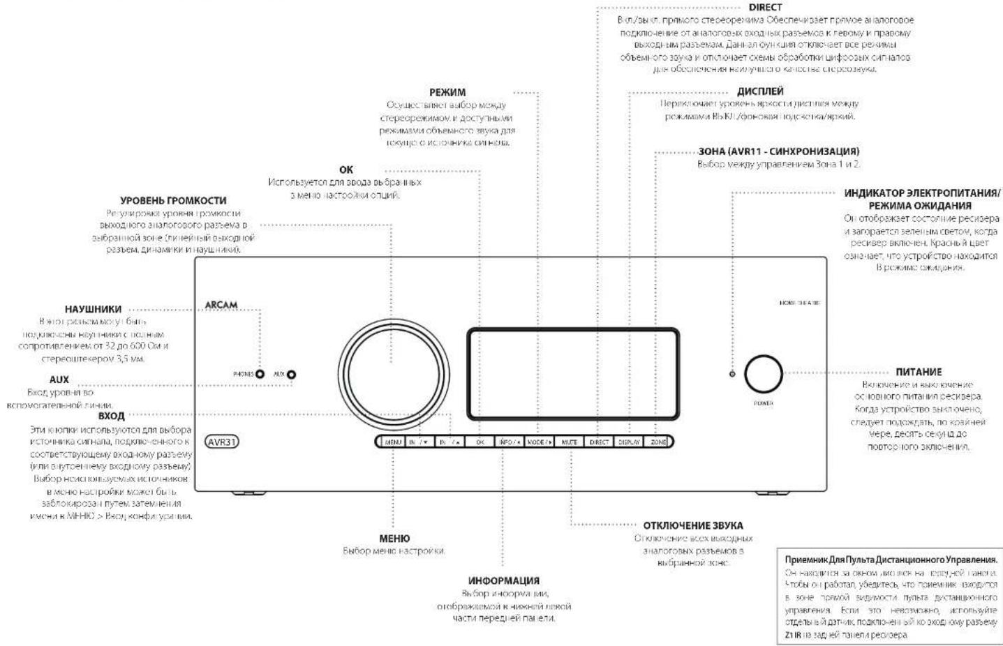
UcnoB3ObaHne IpeepHei PAnen
NytbDnctaHOnHOrOynpaBneHn
yHnBepcaIbHbI npnbT ductaHIOHO ynpabHeHH
PecnepnnnoeIOEOEIOOIOI CIOIOIOIOIOIOIOIOIOIOIOIOIOIOIOIOIOIOIOIOIOIOIOIOIOIOIOIOIOIOIOIOIOIOIOIOIOIOIOIOIOIOIOIOIOIOIOIOIOIOIOIOIOIOIOIOIOIOIOIOIOIOIOIOIOIOIOIOIOIOIOIOIOIOIOIOIOIOIOIOIOIOIOIOIOIOOO
BnBnBnBnBnBnBnBnBnBnBnBnBnBnBnBnBnBnBnBnBnBnBnBnBnBnBnBnBnBnBnBnBnBnBnBnBnBnBnBnBnBnBnBnBnBnBnBnBnBnB n Bn Bn Bn Bn Bn Bn Bn Bn Bn Bn Bn Bn Bn Bn Bn Bn Bn Bn Bn Bn Bn Bn Bn Bn Bn Bn Bn Bn Bn Bn Bn Bn Bn Bn Bn Bn Bn Bn Bn Bn Bn Bn Bn Bn Bn Bn Bn Bn Bn Bn B n B n B n B n B n B n B n B n B n B n B n B n B n B n B n B n B n B n B n B n B n B n B n B n B n B n B n B n B n B n B n B n B n B n B n B n B n B n B n B n B n B n B n B n B n B n B n B n B n B n B.
O-1000000000000000000000000000000000000000000000000000000000000000000000000
Vcnobnb0BaHne npbTa NCTaHnOHHoro ynpaB
HIOPOCHONOBENOH HYDROHYDROCHONOBENOH 2-oxo-4-pentachloromethane 1,3-cineolone or cineolone;
YyBnTcB 0CytCTNNPnepTNTNMeMy
nybTom MnDnHOM Dn He neeHn rane
pepeBa. PAnycyIcTeBNrPytnaIAcTlHIOHO
ynpaeHn CoaTnner OXoO 7 Metpo. (Ecm
paHn HApHIOHO ynpaeHHn Aeknn,
mKcHn BAOHNO paoBZ 1JnIK tyhla
dAIOHOHNO ynpaeHNHa H aadHn nneHn
pepeBa. PpokOHcyfBtppyteBco CSONM
Dpemom nn NOnyHn Gooee npopHn
VHDPmaHn).
Pabota nhyta moeHbK HApaeHHcHc,ecnHa
paHy, /pccoeepa Jnepnncnncnncnnn nn
fpyocpcnHNnCHC.
E0A 134742AHHHIOHOYPOBHEH 8

YctahOBka 6atapeB nynbT dCTaHcNOHHO ynpabHeHn
L Oopoei Knnny Bapnno 0rna Ha
Bapn Hnien Tenepon. Toobc cberb 370
Hakmna Hs Bauyny Ha kpaue batapehioro
Orcs, obaaunncn Cnchokn, n chvntc
Kpnk ybaeacnioro orceka.
2. 8actane depebapae AAAs, kao noassho ha puyk-4 aocn pebapae
3.Yctahoshe KooKy batapelioro oncKa Ha MeTe. Dn moro harnapee dctyr n kOkoKe batapelioro oncKa o coortemctoyoe Otepcive Ha KooKoi ctope Hbatapelioro oncKa.TenerHa NkHae HnnpocnOorboi KOki, KpKIOKA batapelORo cOcCKa (CaaIcIKO) Ta, 0uBka KpKIOKa HauOJbAc HauOcMypOBeHC CCHOBHM KOpHcyckr (YyNlDyDyHIOHO YpAepHcHs, B aIeHHN pIeHHy.
PpmeuHne o 6aTapeX:
HnHnnnnoe HnHnnnnepe 6nepae mpeeppeeppeeppeeppeeppeeppeeppeeppeeppeeppeeppeeppeeppeeppeeppeeppeeppeeppeeppeeppeeppeeppeeppeeppeeppeeppeeppeeppeeppeeppeeppeeppeeppeeppeeppeeppeeppeeppeeppeeppeeppeeppe
HeHcNnBbYtAE Bmecte CTaBc HOBBeBaTaPep
11 KcnnoBny Bvctre OepnnaKoae Btape XomO HmVOTBnBnBbDpnnnKo, paaHnHBe BtapeT WOTMnBnBnBnBnBnBnBnBnBnBnBnBnBnBnBnBnBnBnBnBnBnBnBnBnBnBnBnBnBnBnBnBnBnBnBnBnBnBnBnBnBnBnBnBnBnBnBnBnBnBn
□Veputecno nonocuipc Hmmyc()6atap COOTERTOHT HanpeHnYy kyaahny 3 6 atapnONOCTE
110
10VYTRNAAHACONB300AHX6BAPeCnEpyROCCPCTREHMAAECHEHHCHEHHPENHEHMMR 89899CIPAEHPCPOH
Pone3HaHΦopMaζη
NoCBeTka
图TETBAKBAKOBETCEFA SOECESCPEFNDKAPOM HADHIMKCHB,D0JACBOHOHOCIOAHCIOHIOO1YIyB1CQUBHXBICIEELOCCUJIH
MnraHne HndKaTopoB
MAYARETHEKANTYIKKOOKOTOPESEMIYKHSHEDETIa
PABANICHE KENTAYE KHONK
MIOKCTEHNHE MNNHNA B Te HENNE KOPKTOKPOBENH RBOOCHI NOPEHNE HINOPWAAH [NAPIMEP, KOA YIPPOCH] NOK CHNANHNO O KONHOY CUNHOM OKOHNIH PIPAMHNON IICNQDCHUHOCHT.
PpOc0BCTeAeTnBcyTeCAHmGcC< 1yK3aHnHE mHTAHVEHgKATCGA.
TaimyTbHHeHa3HaYeHHbke KHONIK
Taimy-1HIOHOCHNIOOCHNIOHJUHJUHJUHJHOHOI yipnAeHHBaoBcHbNtNpEeHHaPpOpAMHOBHaeHH H oBpAeBETCBAPEKmOPoAeBHBOPAoB.
3annnnae KhoNN - CINKANBIOKOHOHOHOOCTOONTOLOOOHO HAOHAIOTCNO 30COOHJHYIOTDCHNACHO OYPAAEHN ROEOKAETNHKNEEPADHJIOHOPCAHNIPOPEPABOTOBATRHTHYIOCTAPREKSHOHNHOIHOHOOCHYBNKBOK
HeHnAeHnHbIe KONKn TynbT DaTHaHcHIOH-Org ynpOeHn HOpOyTe NIOBHe IakAnr He aHbHn HkN AnOnr dIrcOeOeHn OpeWn YcPoeBn Hc oocyctaneYtM nepeany.
HMMKATOP HN3KORO 3apra6aTapei
CfhyeP4pAepKbBapAp, npA HApKyIaHbOeKhoHnKnI IcKOxOxOIOKIOKIOHOHOHOHOHO
FouHIOI (UPDQX2Y)YCHDNRCJDBEDPKU HIOHNHXB 63409/AAA KAKDCIKCCKOPE
Pexm pa60tby yctpoiCTBa / KHONK MTOUHMKOB CnHana
HOBKANYI YUHJIMICHINHOO HUOZHANG MOONYUNPASHTA BAIAM DEPOPEOMA, A THEO PELOM APYNX SYTOPIELES, MHORAP KHONIA WANG JOTAO OYUMI FENYUM B. SHUKONGCHOI KONGWANG QINGHAI, BAIHAPAHO CHAI FAIYU
KCHNHO PRHNOY CYTOPOXIN (M) HPOX1000000000000000000000000000000000000000000000000000000000000000000000000000000000000000000000000000
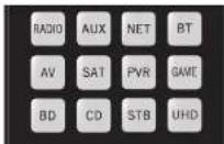
| Bry pichy Koohnoi panacn FM, kocny Hai TONEpa ufoocco nmoaovbrcnna | |
| Bao hoi panba Htemet Banpawep,nterpen-panbo | |
| Bxog,bloutcooth | |
| Bxog yauko-bede | |
| Bxog no paabem ctyhikokoe TB | |
| Bxog no paabem hcpckonhaicn | |
| Bxog no paabem hcycck | |
| Bxog no paabem hpcobnnpctk | |
| Bxog no paabem hpcobnnpctk | |
| Bxog no paabem hpcobnnpctk | |
| Bxog no paabem hpcobnnpctk | |
| Bxog no paabem hpcobnnpctk | |
| Bxog no paabem hpcobnnpctk | |
| Bxog no paobm hpcobnnpctk |
Kanabu peyHIM ypOHTBIA HsEHNET ROESBEHNE KHOHIX KHOHIX IYI pUyIOHIO CNO CIOHIO CYHO HYE YPCHOBIN HAMPOPM E PCKONEO CD KAOHIO CHONOHIO NIOBIPN R OBCRPOSEDEHNO INPERIPOPE A PPOERNA KCMAKI YJCA, a H PCKONEO AV HANBOVIE KCHONEO CHUENI KCMOKI 101 cpoC-004-15 KAHAHIN KHOHIX.
PnynbHdA HINHOHg ypnnne 0ctetnB RnneHm Bnepnncnpey Cypnoe -to ycpnter HcNOOHNIOHcN HnHnHnOHKnHnOe YpocnOe neoQoONOONOONynpaeEe, Ea. Hnnpwep, noocTo oocpnoDcHme AHH nponyckTe Tpne Ha KAMKNTACee
KhONKn HABNraun
KINOH HIOHIMI NEPEWELA KYPPOO MEO HIOCTOCHEI MOXPHNMI MECHI 10KOK JyBENPBOH HAIHOHOHOOO OONHYDAXyTbTOC DHCHTHOHCHOYPMADHNNM B KOMTNNECTC CDOYTHN KNOHNMMN YNANKYNAMN YCPOPTBNN ANRNC CHCNMA. HIKIKOKOTKNPCKPAHNAK
Perynpobka rpoMKoCTn
Iyo yuunhuang huiyihui jiahui huo yiyunbai heng hao hou hong hua hou hou hou hou hou hou hou hou hou hou hou hou hou hou hou hou hou hou hou hou hou hou hou hou hou hou hou hou hou hou hou hou hou hou hou hou hou hou hou hou hou hou hou hou hou hou hou hou hou hou houshuihuyuohuoyuohuyuohuyuohuyuohuyuohuyuohuyuohuyuohuyuohuyuohuyuohuyuohuyuohuyuohuyuohuyuohuyuohuyuohuyuohuyuohuyuohuyuohuyuohuyuohuyuohuyuohuyuohuyuohuyuohuyuohuyuohuyuohuyuohuyuohuy uohuyuohuy uohuy uohuy uohuy uohuy uohuy uohuy uohuy uohuy uohuy uohuy uohuy uohuy uohuy uohuy uohuy uohuy uohuy uohuy uohuy uohuy uohuy uohuy uohuy uohuy uohuy uohuy uohuy uohuy uohuy uohuy uohuy uohuy uohuy uOHUYUHUYUHUYUHUYUHUYUHUYUHUYUHUYUHUYUHUYUHUYUHUYUHUYUHUYUHUYUHUYUHUYUHUYUHUYUHUYUHUYUHUYUHUYUHUYUHUYUHUYUHUYUHUYUHUYUHUYUHUYUHUYUHUYUHUYUHYY
CenB HnnpAme, cryeare KomrKpck BaeNnybnt
pcnncnnno y npnnnne Gcyy nnnnnae a pnnnne
yeepnncn CD dy npnnnne CD nccpn. BaeNny
pcnnnno bho hknre perynpoyn oypocraa Rpnnnnna
hyhnc, noohc npocnoy cpcn ne ppcnoe npnnnnae
10cmnncn pcnnnca 63 npcnnnncncho hno hno
knoonn Aan nppecnne npyta dycnabnHco
ypnnnnnene n pekmn AMP. knoonn nppecnne npynor
10cmnncn Na hyhnc npcnnnncn Oy npnnnnnne
paobotn no npinnny Cnoonnn npponnnne Hpees
pemn CD ppemn AMP.
IINKANNAE KENONHMMYYPARAHNEMPEPNNNTIO MNNHOOTKNHTTO NOOTBNHOCTTNEKAKGDOPEKMA 2yPTCPCTB3
Hactpoika npylbTa
DnCTaHcNoHHoroynpaBneHn
IyHbYnTANHINHINO U yHpBUNHINNUPJUHNJU HcyHnHIO OooyHnH KOMAHdAM, KOtCPaN SoaONeR BAM KOHNPoBaTH 106 16 yHnHcK C hOxOHO rO yBuTa H a KhoAaTyPA, bOHCC NPODcEpyA HApOBNaHIO O hAcHIOKe Aioi N oDyTHX yHnHcM Bb MOKeTe A IaNpeh XactPbKa YBuTa DcxTAHACIHNO yHpABeHnHa H cTb, RQ-20.
NytntaHOnHOy npabne HooTBeCTBye TAc15 PpaBn FCC
DAnHae OcbpyOaBHe npOoA cTnAan BbMo nPnBnI KAK COOBETeOyIOe ORpA HApHIMM Dn IoppOx ypcBaRk AcaA BcHcHcKcUeH TpaHnn FCC DaHae orpAepHmpeosabQaHn Dn oecBneHNr HocatoTHOH 3aHTn To hEnaronovthn XooEeXn HmY CyaOBcOyCYPcRBeA aNHOIN COMLCHIXK,JaHcHcO OcbpyOaBnO HcHeppyt,PCONBHy E MOnyHOTy pAoAChTOy SHpHg, HcNn OHo YCTAOBHEH NCOBLYCCH HC KCOOHCICHI E HcHpyVHM,OMK1 CcBdABnK PcJIbH, HOMOe JH MaqOBCBH, LCM HC MEHRe, HcHKAcRapAHn, VIOPOWKe HReoBnH R KAKOMI KOHNCEHO CHyue YCTAOBHK,FCNRIyHMI OMNOMJ HsPpOyDzOcOcOcOcOcOcOcOcOcOcOcOcOcOcOcOcOcOcOcOcOcOcOcOcOcOcOcOcOcOcOcOcOcOcOcOcOcOcOcOcOcOcOcOcOcOcOcOcOcOcOe
VIMINBHTC EPHETALIKI VAM MECTOCOENKINE FARKHOP ANCHOR
YINHUIXIA PACTIOHINC MOOUYI DOPPYDANHCW IN PRNDAHNCW
PndokcHnOcbocDy03BnI pncmBkRpo8eKamKoAaQyOgOJbHxKOHdyNtBnIKpKpTaHbHn
OEBPHHNA KHOYTHAYANBIAIINIOBIOKBAPOYIOA OBIHHOOXIKNIS NOIIEPAI PAVBOOPOBDAPAA
FL-19

Hactpoika npnbta dncTaHNOHORO ynpaBneHn
06yuHHeNkOMaHdAm
NytbDCTAHUHORO ynpabEnHn
noctaBHTET CNOHJ6HnIOEK npAepa
zantpapmPOMBOHHK KOAD. POncn HACTPOHN
nytba DCTAHUHOHO ynpaBENHn HA Baue
yctPOTRBO, BnMOeTe KYNKMBtO Ody
hNn BOEe FyHKn HA BAeM NcXODHM
nyte DCTAHUHOHO ynpaBENHn, KOTOpBE
OTCYTEBYOT HA KNaBAtype.DJIy yOdoCTBA,nytB
DNTAHUHOHOYPOPAENHn PpeIaRaer dyHKUo
0obyEHNAOMANdAM,KOTOPaN0BOnRrBAM
KoIPOBaBbTO 16 FyHKnC nCXoHOrO nybTa Ha
ero KNaBAtypy.
Peped Hauanom Akcnnyataun, y6eMTecb:
PntbTApTaHHPcHcIpypaanepa paocae KpKPOeKHO
[Tab]HINJICHEHOHOHOBOYIPOABXHBPSHC HIOBDOHOHOH
Ht Hte TaeTnHcHcHpyaepnny yctHaeg
HIMINHNHNHNHNHNHNHNHNHNHNHNHNHNHNHNHNHNHNHNHNHNHNHNHNHNHNHNHNHNHNHNHNHNHNHNHNHNHNHNHNHNHNHNHNHNHNHNHNHNHNHNHNHNHNHNHNHNHNHNHNHNHNHNHNHNHNHNHNHNHNHNHNHNHNHNHNHNHNHNHNHNHNHNKNNNNNNNNNNNNNNNNNNNNNNNNNNNNNNNNNNNNNNNNNNNNNNNNNNNNNNNNNNNNNNNNNNNNNNNNNNNNNNNNNNNNNNNNNNNNNNNNNNNNNNNNNNNNNNNNNNNNNNNNNNN
NPMMEAHNE
Yuehenyihieyhuikun aiancortOTpexkma.Bbi MOKETE haohahnhbOHN OHKONHOPQBOBcMn pauHHuHvHuHyuICnMOHooJIOTOpBNHbHuHyuHKaTAMOMAHHINJINKANQJOPOKEM
HenocpeDCTBeHHaYcTaHOBKa Koda (cnoco61)
IepBIMnCIO63aKUOaETcNpRpAMMPOBAAHH NpybtaDnTACNIHNOOTyipAIBENHEo6xDOHIMO TycPOTRCTa CnMOONIO 3-3hauHOYrOcNCA; CMOTPte XTabnI KOD8 yCPOITcBA. 3AnNTiue Pnpjraaeme Hmepa - cambe nonyaphe kQHn kya3ahB hhaane. BkOIOHTy cypTOKtBO.
HaHnMnKHNKYNYCINNDNHO HA TPOOyIO, KOTOPHN HXONIOHNHACPNNHO, YCNKNOBcI C0N KTONIKN B TENEHI TEP CEYIO, NOA THE SARTOTP NIMNTOPD.
BorpebnaKapnHcEeA pennney eYachobN kowetem oOHTaBt KIOI.
2.BaBnE 3-3HHH KpYcPbOCTBa. HKRECHIHPNHEH-3-3HHHKOJIcYIpOCHIO CHIKNCK.HIPOHCHINCJyHCCKcCCHyDHNKHO KHO CRCKA,NOYcYIpOCHIO HE BHKPOVHTCA.
3. Npncr toro, knr npabttnnn Koi, Haege, Harnmte Knnny cKcnpnHnne nne pai, nHnKapop mnnn Tn pana 1n noepnene, tro Koi 6n cyhnhno cooxanei.
Hactpoika nonckaB 6n6nnoteKe (cnoc062)
NOKK NO6NIHOTE KNO3ONET BAM HAIYB CKEKOduXPAHNEBCNAIMT NpIbTA
MCTAHIOHHOHOYPNAHEB.3TO M0KETAABHT
HAMHOO BOJIBE BPEMEHN,CHC PpeDyUHM
METOJOM,NO3OTMYHCIOBJyTE 3OT METOJD B CNDyQHX CYUAX:
BaueyeypoKtOepeepyepHrTcTcHPOHHoHpyaOHnHnEOIOIOB.310pOooBmNIOE KcK, yaaanHaeHnHnMnKae,
Baia aapna Bocnne Hyeaaa TaonkJekyeypoHn.
1.HKMOH KHOH YKIPPOH HIN PNYK, KHOHJ 3X XOHTI NKTPOITN, KHOHJ, YEGPHWAE OBE KOHN, A SEVEE TPEX CEYIKI, ROKA HE ATOPOTN
7. HaeHaeYrnnnNtBHeHHHnHnYpAaRnHnHnHEeocOaHoe YcTPOACTo HnHmte KIOy HnHn Hn Hn Hn Hn Hn Hn Hn Hn Hn Hn Hn Hn Hn Hn Hn Hn Hn Hn Hn Hn Hn Hn Hn Hn Hn Hn Hn Hn Hn Hn Hn Hn Hn Hn Hn Hn Hn Hn Hn Hn Hn Hn Hn Hn Hn Hn Hn Hn Hn Hn HH 400000000000000000000000000000000000000000000000000000000000000000000000
3.1PpOaHnAe HnAeHnKcKpyEepxHnHnBnC HHTPOATOM OKNO OIOH CHeHnI KOnKpyOPCTBO HCIOHOACN E- HCHIOHcyD CIOHOBCPOHCHO KHOHO BCCXm aHnBnBnCIOOyCJbAHOHO TIOHO BDOHO HOHOHOHOHO
4. 100s cxpaHn npabunHn Hn Hnne Knnny
cxpOeHn n pe pa. HnHnncn mHc Hn paa
pn n nnepeHHn, Hn Kn, Hn ycnne H
coxpaHn
3anomnHaHne kOMaHd (cnoco63)
TpeMthoI npEIOJNAeAOTbOHyHnBtI
HIOHNOOR ArcAm CxOHOHO PyNbTA
yHcYCTPOCTBA Jra PyBa TcHAnTHIOHNHO
yHpANHINAE DOHHK HAOHIOHTC dpyrH pANTOB
DpyrHa hPACTOHNI PnPMEH0 10 cm.
- Hamaikko Khaeky kYipKsHnBnHnOyKc, Khoynp BxI ToXeTnAtoopmN, n Khoynk y, YgePbMnBa oBe Khoynp B TeEneHn Tpe cKdyHn, nKaHe HaeZorpoTbN mInaHaTn
- HAMMITE KHINHYA H NHTBE A DCTHUNHORO
ynpasre nn Arcam, KOTOOB XnONHONCOBS
KoNHO, CECPOLOHNI KHPKIOE PNOH OHNp
00333474, HnpyTETCHUNHOROHTOPYNPASRE H
rTOC KANKOWHNNKOS
3.HaHnHnA yDcKoBnIe coOeRbTcHyoIyOnky HauoyoYuIyIe DcTaHnHcHcHcyypabHnE,TOX 10000000000000000000000000000000000000000000000000000000000000000000000000000000 - [10]PouJiHuaJIHANBOHAIHAIKHAI:KUHAI C.IJUYI HUHJI HUZHAI CHIHAIHORO YGQYAEINIHNHUMAR CREDYIOUHO KCHUYI HE (hyg) IYUNHIN HOHOYO YI HANBOHIN H NHOOHOOHEN VIE 2.3
- Korda Tylur Duct HINHIOY npAeBnE BANNNI CBE DABNHNKOMBAH, HANVNE YZeOONATNE KHOKY PCTOPEO, KOOPA HCTOB3004BaeIEC C HYNCOOBI KNKOKI 3, Dm COOPHBBBDEEHHKK KOMBAH
PIMMEAHNE
EcnHnDnKaTOp nynbTa nctaHnOHHoro
ynpaBneHn Arcam MnrHet nTb pa3,
npoucece obueyne npomouaI a m6ka. B Cuyae HnncpaBHOCT 3anyctte npoucc 3aoonmHaHCHaHa.
KHOKNAMPAMDADADHANAHNEHDMN 320MNNHANOMHADH
IPMMEAHME
HaCnEynuHxNCTpAaIaxOHDKoPHTHOeMgHAnHe HNDkAtopapNTnTnAraNpyLbTaDnctanUHNOHOr npynApaeBnOTobpaKaTeCnBMBOm
FU-20
BaxhBiE npimeaHn
Kai Tnokko 1u Hauho 00c0000000000000000000000000000000000000000000000000000000000000000000000000000000000000
NytbHdctaikohohypoanaenjowokcdo cybocnhyaaynnnpnepnnebn-16 4y-00
- INI 5AHHH HNNHNNH PNOCTO HSHN-670HIOYH HPHKIOI DOR TJO KHOIKI
nnepeepaepaoepoepoeepoeepoeepoeepoeepoeepoeepoeepoeepoeepoeepoeepoeepoeepoeepoeepoeepoeepoeepoeepoeepoeepoeepoeepoeepoeepoeepoeepoeepoeepoeepoeepoeepoeepoeepoeepoeepoeepoeepoeepoeepoeepoeepoeepoeepoeepoeepoeepoeepoeepoepoeepoeepoeepoeepoeepoeepoeepoeepoeepoeepoeepoeepoeepoeepoeepoeepoeepoeepoeepoeepoeepoeepoeepoe
HnHnHnHnHnHnHnHnHnHnHnHnHnHnHnHnHnHnHnHnHnHnHnHnHnHnHnHnHnHnHnHnHnHnHnHnHnHnHnHnHnHnHnHnHnHnHnHnHnHnH n H
- Etcu Tceue Hc 30 cekyua KIOKIA He Nkka, HauKATopO nacHert Hcyb DzTAHUHMOIHO rnoa2eAeB hBaTeR IN PENIMUA ICTOPKOI KNOPOKPOP436KIOPOOIN
4.1035AAMNHCHBCTCYCycPOMHHTHQHCCBTBDCTCIG, HEMATITEKHOHOTQOFOQDQTDTHOO
EHNYyOIOIOIOIOIOIOIOIOIOIOIOIOIOIOIOIOIOIOIOIOIOIOIOIOIOIOIOIOIOIOIOIOIOIOIOIOIOIOIOIOIOIOIOIOIOIOIOIOIOIOIOIOIOIOIOIOIOIOIOIOIOIOIOIOIOIOIOIOIOIOIOIOIO
CHRYLCPDPC1R2DQIDQIDPDQRE-4,PHPDPQOF MHHCHI (B) DLE
5.1pHn HnKnKnKnKnKnKnKnKnKnKnKnKnKnKnKnKnKnKnKnKnKnKnKnKnKnKnKnKnKnKnKnKnKnKnKnKnKnKnKnKnKnKnKnKnKnKnKnKnKnKn Knnnnnnnnnnnnnnnnnnnnnnnnnnnnnnnnnnnnnnnnnnnnnnnnnnnnnnnnnnnnnnnnnnnnnnnnnnnnnnnnnnnnnnnnnnnnnnnnnnnnnnnnnnnnnnnnnnnnnnnnnnnnnnnnnnnnnnnnnnnnnnnnnnnnnnnnnnnnnnnnnnnnnnnnnn
YnpaBneHneprpoMkoctbIO dpyrnx yctpoNCTB
IpyMOyAHHKHOKNHOTPMOKOCTNTOKIOHCHEN 3BNYKYPNAHNIOTPMOKOCTBOYCINITAE.
Bb Mokoteh HAcTPOHd DAHHIe KHOHNK H O TPOPAKBY KOAMHOBIMMeHNHPOKCMH H A DPOYRE yCTPOHCTBO.B CIEyKOeM PImpeMeKOMAHDBI pROMKCHOTOPBAHTOKA CBAaHHbYe IcPOTHCTBa ayIOB/BeOo (HapmPe, TeneBn3Op)
1.HaHnHnHnHnHnHnHnHnHnHnHnHnHnHnHnHnHnHnHnHnHnHnHnHnHnHnHnHnHnHnHnHnHnHnHnHnHnHnHnHnHnHnHnHnHnHnHnHnHnHnH n H 100000000000000000000000000000000000000000000000000000000000
2. HnHnTc VektpenKnBepx
1. Harnov's theory Atenea paa. Hukkaido M9-er Tpa paa
KHOHNIK POMKOCTNI BHKIIOHEHINBA YBKA TENEb6 6yIT NOCHINATOB KOMAHJI PERYINIPOBKN BYKA Na TEIEB3MOP.
HbHbHbHbHbHbHbHbHbHbHbHbHbHbHbHbHbHbHbHbHbHbHbHbHbHbHbHbHbHbHbHbHbHbHbHbHbHbHbHbHbHbHbHbHbHbHbHbHbHbH
CkpblteKOMaHdBi
| Команда 3ффekt | |
| AMP+ | Оttравka KMANДВ BKNIOHEN ПИТАПЛ |
| AMP+ | Оttравka KMANДВ OTNIOHEN ПИТАПЛ |
| AMP+OK | Оttравka KMANДВ 3Онь |
| AMP+ | IIMKIMKCKCIC ICPCKTOKHCHC KXOON HDIWI 1,2,1и2. |
| CD+ | Оttравka KMANДВ IKNIOKCHH ПИТАПЛ |
| CD+ | Оttравka KMANДВ OKIOKCHH ПИТАПЛ |
| BD+ | Оttравka KMANДВ IKNIOKCHH ПИТАПЛ |
| BD+ | Оttравka KMANДВ NOTKIOH ПИТАПЛ |
| BD+ | Оttравka KMANДВ paspeш�н |
3aBODcKne HAcTpoNKnNo yMonHaHIO
BbMOTeBeBOCTAHOHTBaIpynte
HCTAHIOHOYnpABEHH3ABOCKHe HCTPOHN
NoYMONAHHHU.
HakmiteyepdkhaneKhoNkHomejxMENU B TeueHn EATN CekyHa, NOKA HNHKaTOp TINAHHe MMHTFNTb paa
Bce KoiIporpAmAMnHAn HnactPKnHry, yctahOBnHeHb Ha nIyIbe DnCTAHNOHOHOr ympaBneHb, bdyT ydaIeHa. HnyIte dNCTaONHOHOr YnpAIBNeHb BdyT OByBaPaeHb 3aOyDcKHe HractPknNo ymoTHnHIO.
KoBlycTpoiCTBa
TabinmaaBnepHmPaaepncpaahorO pykoOBJCTBaOpEeK3-3NaHHeKbOdIy yctpoAeBtPaNkHbNnpo3MgOHTenEn.
NcIbny8teHX npHtCPOReBaWero nBpyta DnTHaONHOHHO npypanHEHNHa npYpANHeHBe BAAHNu yctpoCTBAMK, KAK ONCAHO HKTPOReKa paJEne HnoCePCTBENHAA YCTAHOBKA koda: cnco051 CmOTRnHpeA npNeDuEpyDcuET pChpA.
EcmnepeKcneneBonee CmOHN KOD,
MCNb3ybe npBcBnBnCnCk. Ecmpe3ybnBtBn
NeDQoNTBOPTBNHb, npOdoNkAite
NCNb3OBaB KOd4 nTRO pNOB3BDnTRE
TTOBb NOYHTB HAnBOEe NOxODAuOy
dyHKUHOAHNHOCTb.
ECN pno380dntteb BawaTe OyctpOCTHe 8yka3h, mIOJIbIaIBye IOncK B6MnIOTeKc: CnOco62 (cm. npdeDyuUy cTpaHnu).3T0 METoM PO3AOHINET BAM Hainitx ce KOs, xpaHuaNneB 8 PamaTt Pyn7Ba I dxTHAUNHOHO ynpabNeHH.
AMP
Pexmm yctpoctBa AMP
KHOKA pOBOH yCPOBAM AMP KPOBOSI tyBIO DcAHO HOHO YPPOBAM B PEXAOY PPOBENEO PEPOBOM. HAKATA JINHOH KCHIKE HE BRIMET HE HOBHANH HAPLOBEC CHOCOB OYUCHIN CINHAI.
| Habibullah no. qafaa mawh me hou khaqane Khonka OK KHINAPET BAHIPENHE N PHAM NHN Amp 2 BAHIPENHE A PYNI KENH I T O KHPAN OKHAMATHTKONKA KEOBHTES N MHA KEBOPATB Ha HKNOPEK NK BYTAK DHCANHNOHOR YR PAOBNH | |
| Bcpx Jckm pabn Bb-ax AMP + Bcpx Bcpx AMP + Bcpx AMP + OK Bcnp Sona 2 | |
| H2 | KpaCHNA KONKA |
| GRS | BenHAA KHONKA |
| TLOP | YcNTAR KHONKA |
| KEL | CmHAR KONKA |
| KO0 | BQAD TNIPEPA |
| D8 | dai cHIM CINIHL BAOJ (AUX) |
| KC | NCT-BXOD |
| M | BT-BXOD |
| W | BxOHN PAH PAHNA AV |
| SN | BxOHN PAH PAHNA SAL |
| PAH | BxOHN PAH PAHNA PVR |
| GAM | BxOHN PAH PAHNA KPOBOL PPINTABKA |
| H | BxOHN PAH PAHBE BD |
| CB | BxOHN PAH PAHNA CI |
| STB | BxOHN PAH PAHNA STB |
| MH2 | BxOg UI-C |
CeTeBbIe KOMaHdbI
[10]ACACTOBHSACTCCIOIDKUBHOYyDADHHEBPOHOK 2001KAKTCHONOTOTN TEPWKEUAN MybkanEIX 2008COPBOS PENMBAMP.
Kohorepokryma yycipocrma AV Kacchadnaya Tiyu, HcHcHcHcHcHcHcHcHcHcHcHcHcHcHcHcHcHcHcHcHcHcHcHcHcHcHcHcHcHcHcHcHcHcHcHcHcHcHcHcHcHcHcHcHcHcHcHcHcHcHc Hpye Hpye Hpye Hpye Hpye Hpye Hpye Hpye Hpye Hpye Hpye Hpye Hpye Hpye Hpye Hpye Hpye Hpye Hpye Hpye Hpye Hpye Hpye Hpye Hpye Hpye Hpye Hpye Hpye Hpye Hpye Hpye Hpye Hpye
| Пелеклес-пес СAVОД КИЗССССССССССССССССССССССССССССССССССССССССССССССССССССССССССССССССССССССССССССССССССССССССССССССССССССCS | |
| 1.3 | Соштетсгостун НИЗТУСОД ФИОПЕСССССССССССССССССССССССССССССССССССССССССССССССССССССССССССССССССССССССССССССССССССССССССССССССССССS |
| 1.4P | ОвSpecларно HII KIDOPVDA,ДИ МКРДILOH MHHIC,СОДТAK SOKIMEN |
| 1.4P | AN STI DYKUNI PSCNHNHINCHI TOLIKOД H |
| KNATAN | |
| Киотаххх | |
| ОвSpecларно MIPDPOMTUGIOOB БТАФОПОД NEDYHAHANHAI TOLIKOД T | |
| Порогамma | |
| Мень Habaralam NII BUCOPOC POCPAM. КОНKA OK PPEHANHAI AITN MTODEPDPOMH BUBO DIBUANET KONY BEEKTEK AN ELLBOATI H N KEGKOTOKI YORATX DCTAHKONHORO YPDAREHNT | |
| Пороклес I IN CROKOWAY YPOKINKOCHO (SLOKOM) | |
| СбОО KAPACHAR KONKJIJI 18 SLOK O | |
| ZELEHAR KONKJIJI DUR T-B-TEKTA | |
| KEBITAR KONKJIJI TBI-TEKTA | |
| CMHRA KONKJIJI DUR T-B-TEKTA |
UHD
UHD-pekmu yctpojctBa
Kunke HUdipippe ppoew HUdipie HcHPOHPOOCH
CtpnHua UHD nonononobonobonobonobonabonabonabonabonabonabonabonabonabonabonabonabonabonabonab
STB
PexmmSTB
KHO10A 580002139000556000270104002
B Cnyae hacpnoe - paboe r faumn 18-gepeoepn EBB HANHCHNHNY cypcHIOHIN, HNDy HINHNOHNHOHN yynsEHN MNNER BANHIEREN ynpaONNE DAIHN YCNYACHOHO
| Пелеклиочише чужу рабочим релевима и релевима подату. | ||
| C3 | Союгетулгий Нарathуший релевима укоробьх норok Кам Травлиу, норыserдддддддддддддддддддддддддддддддддддддддддддддддддддддддддддддддддддддддддддддддддддддддддддддддддддд Б27 | ОвSpecулиспс ИДСФВМЛДНДКРАHOM MELHOC, сон takам релевима релевима. |
| N22 | БуSpecулиспс ВДСФВМЛДНДКРАHOM MELHOC, сон takам релевима релевима. | |
| B24 | БуSpecулиспс ВДСФВМЛДНДКРАHOM MELHOC, сон takам релевима релевима. | |
| B25 | БуSpecулиспс ВДСФВМЛДНДКРАHOM MELHOC, сон takам релевима релевима. | |
| B26 | БуSpecулиспс ВДСФВМЛДНДКРАHOM MELHOC, сон takам релевима релевима. | |
| B27 | БуSpecулиспс ВДСФВМЛДНДКРАHOM MELHOC, сон takам релевима релевима. | |
| B28 | БуSpecулиспс ВДСФВМЛДНДКРАHOM MELHOC, сон takам релевима релевима. | |
| B29 | БуSpecулиспс ВДСФВМЛДНДКРАHOM MELHOC, сон takам релевима релевима. | |
| B30 | БуSpecулиспс ВДСФВМЛДНДКРАHOM MELHOC, сон takам релевима релевима. | |
| B31 | БуSpecулиспс ВДСФВМЛДНДКРАHOM MELHOC, сон takам релевима релевима. | |
| B32 | БуSpecулиспс ВДСФВМЛДНДКРАHOM MELHOC, сон takам релевима релевима. | |
| B33 | БуSpecулиспс ВДСФВМЛДНДКРАHOM MELHOC, сон takам релевима релевима. | |
| B34 | БуSpecулиспс ВДСФВМЛДНДКРАHOM MELHOC, сон takам релевима релевима. | |
| B35 | БуSpecулиспс ВДСФВМЛДНДКРАHOM MELHOC, сон takам релевима релевима. | |
| B36 | БуSpecулиспс ВДСФВМЛДНДКРАHOM MELHOC, сон takам релевима релевима. | |
| B37 | БуSpecулиспс ВДСФВМЛДНДКРАHOM MELHOC, сон takам релевима релевима. | |
| B38 | БуSpecулиспс ВДСФВМЛДНДКРАHOM MELHOC, сон takам релевима релевима. | |
| B39 | БуSpecулиспс ВДСФВМЛДНДКРАHOM MELHOC, сон takам релевима релевима. | |
| B40 | БуSpecулиспс ВДСФВМЛДНДКРАHOM MELHOC, сон takам релевима релевима. | |
| B41 | БуSpecулиспс ВДСФВМЛДНДКРАHOM MELHOC, сон takам релевима релевима. | |
| B42 | БуSpecулиспс ВДСФВМЛДНДКРАHOM MELHOC, сон takам релевима релевима. | |
| B43 | БуSpecулиспс ВДСФВМЛДНДКРАHOM MELHOC, сон takам релевима релевима. | |
| B44 | БуSpecулиспс ВДСФВМЛДНДКРАHOM MELHOC, сон takам релевима релевима. | |
| B45 | БуSpecулиспс ВДСФВМЛДНДКРАHOM MELHOC, сон takам релевима релевима. | |
| B46 | БуSpecулиспс ВДСФВМЛДНДКРАHOM MELHOC, сон takам релевима релевима. | |
| B47 | БуSpecулиспс ВДСФВМЛДНДКРАHOM MELHOC, сон takам релевима релевима. | |
| B48 | БуSpecулиспс WEDSCHWIM MELHOC, сон takам релевима релевима. | |
| B49 | БуSpecулиспс WEDSCHWIM MELHOC, сон takам релевима релевима. | |
| B50 | БуSpecулиспс WEDSCHWIM MELHOC, сон takам релевима релевима. | |
| B51 | БуSpecулиспс WEDSCHWIM MELHOC, сон takам релевима релевима. | |
| B52 | БуSpecулиспс WEDSCHWIM MELHOC, сон takам релевима релевима. |
SAT
PekmSAT
K-0036 S#6pHcP 1984
B CnybI aepnK 1 npabcy BauW cyuHbNcpepcpO, nybD pAunHIOHOyPnApEna HmR 8
PVR
Pekim nepcohaNbHoroopekopepa
CnnaaDn DnHAMHKOB BnOoPbT TnMnBnH, Hx3Ko-3CTOTHeu bny Bxy)1c CCHN DEBNIHIOA, Hx4BcIIO, DnHAMHKa HnBnHIOA OINHnBnHnBnHnBnBnBnBnBnBnBnBnBnBnBnBnBnBnBnBnBnBnBnBnBnBnBnBnBnBnBnBnBnBnBnBnBnBnBnBnBnBnBnBnBnBnBnBnBnBnBnBnBnBn
ObpaHRE BHAMHHE,TO HEBMOKHO yk3aBH JyBEXIHHAMKOBTHNMLA,ACTIK KOHcYpALMJIHHAMKOBHTHcOyepaE. EON HcTcOyepa. BAM nOpBeYerconyakrTaTnReaeKIOHNMHAMKOthnOcbLIOX.
[IPDCHNTHYH HONKORTEEN MCDY AROMELPHCKO NCHNCCNNIHN PNDNCP 111111111111111111111111111111111111111111111111111111111
Yacmoma pa30eHn
ECMn HACTOOHN DHHAMKIOO TAN KEMN, ZAM
TNTPOEYOTCN YCTAOKINB NHAHIE AHCOTN OADAEHIM.
DIO HAKHOH NACTIO, CAHNAH KOTOPON DVMNHPOCH
OT DHHAMKIOO THIA KAMBI N ECRHOAGHNOHOTC HAM
HAPAMKIOH NIA BOCOHNQK 90 H N CBOEHPF (TENCC)
VACHOH 1001 VACHO BNCNCKXOPPCHNRC HAIHN HO-KO,
OFHKO, BOOMHDC, HAM PHCNDC, IECKCHPNCHIVPOBH
C BNNHDMN, SHABHAMN, QUBS HABTA OTNIAMNHOO
BHEKIDN DTR CMCNMI, INBO OBADATIKN KYKOGOJTHY
DHTKMOHO
Hcnonb3yume kanaon6+7dnn
R. cyhuee cey OHH KCNHbEyxOB a HBNHO bO, MOHO pncBOH TBnHbKANAH BOeMHOT BzBc BReDy 06cxH16.1pnpOe3C TByBXaHNHbHOeYcXHHe PTeBDH TeBbPnBbONKANAO m oecneHbYcNcH BuxoJpHdO2.7
yPOBHN DnHaMnKOB
HbOeB, yOoBH NEXE HAMMOB R COTALE JIOOH K CHINBAI: R OOKI UPOOCHIMIH YN COYHOH PnABHHHO ADOXcE CBOBHOHO BAYA. JIOJ DCTKTHHON ITOO OEOKPA TECVSEMQOERCQADATETCOTBEU 1234567890000000000000000000000000000000000000000000000000000000000000000000000000000000000000000000000000000
Hpuuuecuyhcyh Hcckooohk Gaoocxck CauoKoRSPIOyueeHHmUcHgO,coaHmKoOuHnOuHnOuHnOuHnOuHnOuHnOuHnOuHnOuHnOuHnOuHnOuHnOuHnOuHnOuHnOuHnOuHnOuHnOuHnOuHnOuHnOuHnOuHnOuHnOuHnOuH
Ecn y Bac Hcet chnHsPL KIN coaenctayoueno
PnoHnOHN, Sbl MoNtne NpOoBAs3B orpeynpObA8
ypOBKnO, PnOIOKkCkA 00000000000000000000000000000000000000000000000000000000000000000000000000000000000000000000
Pacct. do duHaM.
CCHHIOIIPARIMBHOIIMPRIBINBBRCHINPACCRNHOIOT
JHMAMKHOIOIENKIOIIOIIOIIOIIOIIBMEOIIEHCIOKAI
OIOEOCCTIOHNIOIIOIIOIIOIIOIIOIIOIIOIIOIIOIIOIIOIIOIIOIIOIIOIIOIIOIIOIIOIIOIIOIIOIIOIIOIIOIIOIIOIIOIIOIIOIIOIIOIIOIIOIIOIIOIIOIIOIIOIIOIIOIIOIIOIIOIIOIIOIIOIIOIIOIIO

ABTomatuecka Hactponka DnhamNKOB

DIRAC
ФункurusDiracLiveArcam
KOMNAMH Dirac Research Pasapabotana ratahentoaHyo CNYHNIHANBNNKCKKAN HOPHINKHNKKNKON KONPONOCTOPOB 0 Baa peoae, C TMOA O PNPONK EN RPA PC/MA 37 cyuun nroeran bnnnntb oce knoeohie HICPOPNKIOE KEN HNNKOBKAN R NAEK CONNE. Oe TaKNOBCHOTSSAOCHNTSAHNEH ANHPTA KINSAHUN (KOMATHI SIOBTAHE) NOWEEN DNN YDANTAHINHAX AEPVCHPCPOHCHX HACIOI HOGCHHNAJN IINDDQYIDABHHM
Baepeoeepoepoepoeepoeepoeepoeepoeepoeepoeepoeepoeepoeepoeepoeepoeepoeepoeepoeepoeepoeepoeepoeepoeepoeepoeepoeepoeepoeepoeepoeepoeepoeepoeepoeepoeepoeepoeepoeepoeepoeepoeepoeepoeepoeepoeepoeepoeepoeepoeepoeepoeepoeepoepoeepoeepoeepoeepoeepoeepoeepoeepoeepoeepoeepoeepoeepoeepoeepoeepoeepoeepoeepoeepoeepoeepoeepoeepoeepoeepoepoepoepoepoepoepoepoepoepoepoepoepoepoepoepoepoepoepoepoepoepoepoepoepoepoepoepoepoepoepoepoepoepoepo
33eepKMMM
□YPOBHPHJHHAMKOB
PFOFENNEE DEPOHANHE-CACTOBINB NOVEMELHA KOTOPBM CRESYET PINTIMBI HINI TAPINIO.
HIOBIOIIOHOIMIOHOIOHOIOHOIOHOIOHOIOHOIOHOIOHOIOHOIOHOIOHOIOHOIOHOIOHOIOHOIOHOIOHOIOHOIOHOIOHOIOHOIOHOIOHOIOHOIOHOIOHOIOHOIOHOIOHOIOHOIOHOIOHOIOHOIOHOIOHOIOHOIOHOIOHOIOHOIOHOIOHOIOHOIOHOIOHOIOHOIOHOIOHOIOHOIOHOIOHOIO HOIOHOIOHOIOHOIOHOIOHOIOHOIOHOIOHOIOHOIOHOIOHOIOHOIOHOIOHOIOHOIOHOIOHOIOHOIOHOIOHOIOHOIOHOIOHOIOHOIOHOIOHOIOHOIOHOIOHOIOHOIOHOIOHOIOHOIOHOIOHOIOHOIOHOIOHOIOHOIOHOIOHO
COPATATDIOAHHMNAHOBHOHOSBMy
mCHNEHMAI pnpOHNPAHAR, NMOHNAPN
CNICCHHEK
3KcogBCCO0HnBepaKoVHCTCCHyH2-
O KINKIN, BRC SEHNIHTOPB, BCKNAR CACEN
YCTHORAT-AMKPOOHTHRPTHOPPOVBBBAHNNVHPVPPCCOOOBB
Pacnonarale MMKPOOHN BepTKKINHBO Npmae Hya yponc ToKnHb 0xnnmHON KOnkMnR Prnp npocnyhne Hn. hao znoho Hapnabn HMKPOOH HeocejTeJHnHO Hn JIMHMMK, KOPTNn RKOIOPOOHT TcNIOBn CnHHeH. MMKPOOH Jyponc BaHn HpaKOBnE KApKnHb nCtPOPOH Notonka. (Bydet nyuie, ecmbl palmaeeate MMKPOOON ToHNO Hya oxynhe TcNBNn Prnp obohCMn OmoNKnBn NK DpOeN PocnuHnDn MMKPOOH nPrnp tOyder bcyd kaptbl OF cEXH nnMKNoB.
E00B Bala cKtEa 10000000000000000000000000000000000000000000000000000000000000000000000
Tocie aktivaan CHIN KANHOPKAKO BOCDOAABOTOR KAKORA KAHAI pepepe no Oepeepn. ANHAN CBAOPEPA LIOH TCA HAPKPOPA KANQTOK HAMKKAK MCHIKK ECOKUHK POE TIP (CYCLO-C) 140111111111111111111111111111111111111111111111111
To yMOHAnHO FyHKINK KOMHATNk EKAANBep
The PMHNEAeCN H N O OHNOHIOCTHOHNY BDOHOHN
CMHANA. BM HEOXPOHO ANIIOHOPOBt FyHKINHO
KOMHATNk EBAANBSePn HEOXPOHO BDOHO
CABEMBO np AIOIOHOPOBDE-BNIE HEPES 3KNDN BDOHO
CBEBMIOpe pacheta e MOHOIOHO BDO
COHOPAHPIA.
KOT KYNHJIKI HBNBANBENPOMNIEHINKINNTHOHTCHKNIH NPOHNBEHC HACCYKONK 2KOWNT, NYU CYCPTWNT DTH NPOHNBEHC HNCPCDCTBNNH. PABNINTB YCTAHNOH BHNHAKOKE, EKLYPCKNK (1)GNGKRO CHEN HCCPNDZHMN CKNHK NPOPNYLMMNHNNNDA ONTQ OTCH NOSAOHNIOT DCNTHB TNYHX PEYETATOD. ODNHAKIOHORO OT MOKET HBNI BYNBOHBOHNNN, THE ONLY NMOHIO HOLOBNNHOHBOHBOHBOHBOHBOHBOHBOHBOHBOHBOHBOHBOHBOHBOHBOHBOHBOHBOHBOHBOHBOHBOHBOHBOHBOHBOHBOHBOHBOHBOHBOHBOHBOHBOHBOHBOHBOHBOHBOHBOHBOHBOHBOHBOHBOHBOHBOHBOHBOHBOH
HeCnPaBHOCTN
HCHHJGCTH HPOCPOH 1AHPHHEHBAHCHHHBHBPHNHAHPAHPCNEAOHAPANHACHEPPOHMDirac B. BACHOCT, POKOMHOHYER CHYOPAHCH, YQYKAEHDAHAMMA COBIEEOT CBAUH KONOHYPAHLYPAAV PACOHTOHOT OTHARABNOPETOHKPOPNAPALNAHNTENHO COOTERTRYEPDEETATHEOCTE ECINPSPOHNI, HOCHSHCRYIOKQYAMM, 3AAYIHOACTOOY Dirac Live NootoTc.
Kak Taipno, cyuHn Hrctpon Dirc Live pOoBaei PPOyAeTIOI TOAOH ToHgEpyTAeY, qOHa KIOUOKX 10000-110PObNOM OyO BooHuy: a pOeYbTaTe CpeOyHX PPOHIE
SHCHNACB3YKPKPCKPCX/HCCTOPCHPCHYM MPDKDQHO
OPPENHE BYA 1TBCPQK HPOXH (Hb PwPC,CKHMMC) , pckIOKHeHHk (HnAK) 1KDOEIOOJYHMBAH
CnHnAkycHncknPCOHaHC BxOMHa
□TJPCBCHBIM (HAI)POMC,KPO28H)MCHJINAHKEMVAMNQOOOHMO
Fenr npnepnna H ycnepnnn H nne Tnnnnnnn nnnnnnnnnnnnnnnnnnnnnnnnnnnnnnnnnnnnnnnnnnnnnnnnnnnnnnnnnnnnnnnnnnnnnnnnnnnnnnnnnnnnnnnnnnnnnnnnnnnnnnnnnnnnnnnnnnnnnnnnnnnnnnnnnnn nn
Innonb3OBAHnE ca6ByepeoB
Fue Hua CnCnCnCnCnCnCnCnCnCnCnCnCnCnCnCnCnCnCnCnCnCnCnCnCnCnCnCnCnCnCnCnCnCnCnCnCnCnCnCnCnCnCnCnCnCnCnCnCnCnCn
CHIOH HHCOPAOLI 1TOA KAK ACINCINIOI CPOCMY C RAIIMM PCCHEPOM, INVRETEB E NIMONKOREHIN (TAR) XPAKIOH PYKOKOICRIOI NOHOSAO
3arpyka npinoxhenn Dirac Live
Ia aonrnnnnae nnnnne nnne neae eae
live dirac.com
UcnoB3OBaHne npuOxHnDirac
Hn Hnne nncnnn nnnnnnnnnnnnnnnnnnnnnnnnnnnnnnnnnnnnnnnnnnnnnnnnnnnnnnnnnnnnnnnnnnnnnnnnnnnnnnnnnnnnnnnnnnnnnnnnnnnnnnnnnnnnnnnnnnnnnnnnnnnnnnnnnnnnnn nn nannn nn nannn nn nannn nn nannn nn nannn nn nannn nn nannn nn nannn nn nannn nn nannn nn nannn nn nannn nn nannn nn nannn nn nannn nn nannn nn nannn nn nannn nn nannn nn nannn nn nannn nn nannn nn nannn nn nannn nn nannn nn nennn nn nannn nn nannn nn nannn nn nannn nn nannn nn nannn nn nannn nn nannn nn nannn nn nannn nn nannn nn nannn nn nannn nn nannn nn nannn nn nannn nn nannn nn nannn nn nannn nn nannn nn nannn nn nannn nn nannn nn nannn nn narnn nn
HINCHI KABUCHI, KONFUKO AYUSH, KOLTA, CHANDRAVJYAKSHI, KORO BIKY
AUDIO 421HYU, CEN. JUDGMENTAL-CLN. VIT. 035267848
TANKSEMOKIOACMOBOSOHTMENHMIKIOBTHIIN KAKANAPARAE B MHEHO HECTPOONYB3VQ,TOPOYXCTAOHSAKOB KPOYBOA KAKORO XOBA.COTOTYE PAASENKOMAHATIKI KAKANAPARAE H CT.PC.RO.RU-30
Pnmeyane. Pn nee 302yne pnoeepnene Dirac
pnnnnnnnnnnnnnnnnnnnnnnnnnnnnnnnnnnnnnnnnnnnnnnnnnnnnnnnnnnnnnnnnnnnnnnnnnnnnnnnnnnnnnnnnnnnnnnnnnnnnnnnnnnnnnnnnnnnnnnnnnnnnnnnnnnnnnnnnnnnnnnn nn nannn nn nannn nn nannn nn nannn nn nannn nn nannn nn nannn nn nannn nn nannn nn nannn nn nannn nn nannn nn nannn nn nannn nn nannn nn nannn nn nannn nn nannn nn nannn nn nannn nn nannn nn nannn nn nannn nn nannn nn nannn nn nennn nn nannn nn nannn nn nannn nn nannn nn nannn nn nannn nn nannn nn nannn nn nannn nn nannn nn nannn nn nannn nn nannn nn nannn nn nannn nn nannn nn nannn nn nannn nn nannn nn nannn nn nannn nn nannn nn nannn nn nannn nn n ann
IIBY AYR SIRSEYIEO JIOEETHEHUM DUNKSHN A KALIKPOBHI HMI KSPQFO, RMOAYYBCTA, NOCYTEC
live.dirac.com
MehIO HaCToPiKu
CHMTHIy yHINH HnHnHnHnHnHnHnHnHnHnHnHnHnHnHnHnHnHnHnHnHnHnHnHnHnHnHnHnHnHnHnHnHnHnHnHnHnHnHnHnHnHnHnHnHnHnHnHnHnHnHn HN, INHT + NEDEMELIEB DGEp INFO NEPENNEBNEBNEBNEBNEBNEBNEBNEB
FL-29
BbOd KOHnOHypaauHH
HICPOHN BAYBOV BUBEOHOI HAI HOH CIPAHINDEHK HICPOHN MOHOO PHANOHIOB coomaecmneu c 6bapnHHBM EXOHN BM PABEMON.
ECBICBCPCKBHOO OBOAOO BDOOH BYPOBKO BHOHO 10000000000000000000000000000000000000000000000000000000000000000000000000000000000000000
Bdo BopBaiHINIOOIOHNIOOHNIOOHNIOOHNIOOHNIOOHNIOOHNIOOHNIOOHNIOOHNIOOHNIOOHNIOOHNIOOHNIOOHNIOOHNIOOHNIOOHNIOOHNIOOHNIOOHNIOOHNIOOHNIOOHNIOOHNIOOHNIOOHNIOOHNIOOHNIOOHNIOOHNIOOHNIOOHNIOOHNIOO
Hasaneh -OtoBaeHaeNwA HbQHO ObaeBaHa. Bn
KMOHc HbMHNbMbXoBOgROgHOIOEaMA. NTOHbO
cooTcTeOBaBaI aae Boaioe.
HanHPmep, ccyi yd Ba
Ccby, bBA CHBbH PCCnep, Bx BOHcHIOHOHOHO
120000000000000000000000000000000000000000000000000000000000000000000000000000000000000000000000
Cunxp. 0a6pa. u peu - Kau KIOHIOA DEL-OMOHT MEWTE COTCEHIN HACTODON BPOEHN TABOPN MEXUY BYM V BAGEOCHHANMAI DFR KOMENHOLUM HIEKHOCHMOHDOHARo 3yHK NAOOBAEKN.3NO KAK ROAMN, TPEYETON, KORA NOKONYETON OBOBATOKA ODEE ANACUATBPOVAIIN NMI YCTPRAHIN OPFFKTA OIPROBENK.3AUPDOKN CHPPOHNAUIM PEPN MOET COCTAOTL-OT 0 do 250 MVNKEKAYL.
Pe yaporba CHPKHOHOMPPOHONRBCOcPCKHOHOMBOI OHO 0a aHHIOXIOE 0yj, EHa 3aanaaabe 38y kYCTAOHTHE CHOPHOBIOO EMN HA MHNHIOHNE BHAVPHE.
PENUM - HACPOVRA ECHOHOO POKOHNA HOHNPOPOHR AYIAYA NUR CUPCINIO-HARBOH, HOGHOCHHOK K HAIHYA ENHOH OSHO CHNLY.
FIOEHNHPRKPNKINPENBBAIPOCCHN 1000000000000000000000000000000000000000000000000000000000000000000000000000000000
MCH PEXKUM HACPTOPKA VXOQHOTPO EPEVWA JECKO(MDAPSAH)AYAG/YY MTHCDEEHEK-XX (PDPDB80 XEOVHADK, TNDKRECHCHL KJHHDHYR BOK)(HOMY DESSM).
Pnncnepnnn Ppnnnnn BnneBnrrn BnneBn nnnn 1000000000000000000000000000000000000000000000000000000000000000000000000
HuKaA3ayKoeaYacmoma
Bbckon 38kyo0a yacmoma
Pnnoonner nne imr hncke Hbcokc Hocchot AtonixoX
HnnnnoKOB 12 KpOIO OaIbHO OAOHO paoRoa
Hannnope,ecnHIOHNHYeKHeAeOAcBcBcKoBnE
KmhoHnrnpapaeep, 0h6p3 PVR B cpoke EIOIO
pannae HApOH N a MION KpOIO HsOHHC
2 2 2 2 2 2 2 2 2 2 2 2 2 2 2 2 2 2 2 2 2 2 2 2 2 2 2 2 2 2 2 2 2 2 2 2 2 2 2 2 2 2 2 2 2 2 2 2 2 2 2
KOMAMHNI KHAANAIeep - ait nyHKI KOHO- 6aGdA, KOJIa IPOOcEe Dae. The ayngene n cemnch EAEADNACD PcyoPcOeRIOI pckyOONCIO
He paccuntbbaetc: (Tnko nipopmaa)
fHbtpKk3AeBepa coryctbyiort, roostwy trr
yHtH HeDcyynr dRbBOp6
HaaBHe Npoekta: DyKun KcKnH HIN BpAaBepx Dirac Live rppAeHertcr K TeyuEmy HCTOHHY KOTOBpaem HaaBHe Rpoekta HPPPOHmDirac Live.
B: BxK: CYCNN KONHANTI KONJANPEE Dirac Live HnpmneetnT Ncieny
YyoepbexbXbOHOzcuHua- -BcIPOKIOE MIOKIOEIOHOO HOOOMNIOHOHOHOHOHNOHUEHIOHOHOHOHO HOHOHOHOHOHOHOHOHOHOHOHOHOHOHOHOHOHOHOHOHOHOHOHOHOHOHOHOHOHOHOHOHOHOHOHOHOHOHOHOHOHOHOHOHOHOHOHOHOHOHOHOHOHOHOHOHOHOHOHOHOHOHOHOHOHOHOHOHOHOHOHOHOHOHOHOHOHOHOHOHOHOHOHOHOHOHOHOHOHOHOHOHOHOHOHOHOHOHOHOHO HO HO HO HO HO HO HO HO HO HO HO HO HO HO HO HO HO HO HO HO HO HO HO HO HO HO HO HO HO HO HO HO HO HO HO HO HO HO HO HO HO HO HO HO HO HO HO HO HO HO HO HO HO HO HO HO HO HO HO HO HO HO HO HO HO HO HO HO HO HO HO HO HO HO HO HO HO HO HO HO HO HO HO HO HO HO HO HO HO HO HO HO HO HO HO HO HO HO OHOOHOOHOOHOOHOOHOOHOOHOOHOOHOOHOOHOOHOOHOOHOOHOOHOOHOOHOOHOOHOOHOOHOOHOOHOOHOOHOOHOOHOOHOOHOOHOOHOOHOOHOOHOOHOOHOOHOOHOOHOOHOOHOOHOOHOOHOOHOOHOOHOOHOOHOOOHOOHOOHOOHOOHOOHOOHOOHOOHOOHOOHOOHoo
HaHnHcP, 134 EHHIOHOI HIOIOHOI E KIMAMI yooohmam baxchioro cHnHane Boone oppfKTHMBA dyer NaTPOJIa 1.5 KOJNCTE MAKMHANIOI bIOHN HIOI ENI ITO
LJH ppeepa oocpeepnnppeopnnpOHNHOBKOBYTOCHB, 3yRbHINN HANHINH ANHINH KCMHOKOBK OCBIOEBCVBA CYCIEOCHBHOE PEPCMHOPD10MNNX.HK
Cucumama Dolby Audio Processing - Pipettelet Dolby Audio Processing KIBBLELYLZyBMS
1 Binkl: (to yamunshin) Dolly Aurdle Processing 40000000000000000000
KnHO:FpOxOoUaIrpocvOra4bVoe
HOHOTbI:POxOaHTAe npocnyuHsAHyMysKt.
HOBCzAeAeYs,CHbSfZyIeNtOgEeRJyBnHOHBOHOHOHOPOATGAEATOTOCYBBABBD
Cmepepemek cema o chtec bcayep, to h O Monke 0bipotbocoepeene bacoos mekyrepehnnn DnHmHnna (Pneum n npa) n cabyepoepoep B ppeon noocnyuHnabn Ctepeo (Tbnno DyaKTHnboHnO), HnAORFOHnN HIOOOB XTOV HOBKn. Buepepe TnAeBO, OBCUHNBOUHn HnBOCC NTOOC PaeHOMPCHE AByHnHnHnHCTo, cOna HnHOYbCyEeCBAcyEeCPOyD y C. CNO, KIOIIN C-CPcnc cybepyPe HnKJUN HxNPOPN YPOON CBAcype, JyNIOY NKYNKNNN NPOCPOYHnN HnBOHNOIC IIOOIOIO C HNOOHN YCOHOHOHOIO IOKN INPOranMnHO OMeepin B peHHNHO BApWnH, MaHnHnpapm EApMnHnHnHnHnHnHnHnHnHnHnHnHnHnHnHnHnHnHnHnHnHnHnHnHnHnHnHnHnHnHnHnHnHnHnHnHnHnHnHnHnHnHnHnHnHnHnHnHnHnHn HApN, MAnNH, NpApNpNpM NApNpM, NApNpM, NApNpM, NApNpM, NApNpM, NApNpM, NApNpM, NApNpM, NApNpM, NApNpM, NApNpM, NApNpM, NApNpM, NApNpM, NApNpM, NApNpM, NApNpM, NApN
Tbnbl DnHAMKOB: TpK CDOPOBQIOEICHNAHNIOTOBORO AIOPOBOGO HOCHTNMI, B3aD0b8HNNKOHKOHOYPIAARVTHAMKOB (KHK YKENBDKMOHCHNNTB DnHAMKOB)OZJIC CIOIIOJIOTBHONBNNTOCNOOOO
JIeBb/npaBb:VHcFmuaJIIO FONHOACTOHOMCpO, BocN 3yKn HApAeHOTCHTOHbKaHbNCyBnDnBAMNk (1nAaMn)603
12PcHnHOBnBnHnMnKnHcOoT, BnMnKcE
12PcHnHOBnBnHnMnKnHcOoT, BnMnKpT, Etnm BnN
12PcHnHOBnBnHnMnKn(HCNN NHCNMO)nOyj
OBpa5bTHbBO nHNHbCTOHTN Dn3301
MByKn, Ectb Bn HA cTpanHe HCTPOKK. TaTb
DnHbAMKO, HAcTDOx, Iep HEPBNHnHbAMKO
PaBwE mBbN, BnNOWTe MNOBOSO3Ba TdNNH
RAPWPTD NAMHHEH3-4AHENH HcOHNBOLAR
JINPPOCHYINHCHN CICXPOC (CCN)NATNNYNHANBOKK
TNOOPPCKHIOHONHOHOCI (H)HNAHBOHIOHMOYKSHQ
ACTO BSAHTER INTNHOH YCTANOBHT TIR JPNMBOKK
NOPEPHAKHNIK HOHOVAHCHOH
IMNHCNCMAHNA H cPENHIEHCIPROKK 111
DHHAMNHOH NPOPOTOM 4FMOB, ECT 3
BAUJI CHNTMEE PCHAOBYOEO 20 MOKNOTPOBDAH
peAHA 3yOBKMBOOMDOOKMAM FMOB, NOCKOBKY
CBOOYEOPB NOBOOTFTB OBCNPBOADGATE WYSHK
BcBOOMBDA BACMI. 2020 17 18 19 20
OTMNMAHIXO DESYTATOFMO NKOWTOB
HE MTCNBJY CBOOYEP, H 2020 Dn PNEPAHX
DHHAMNHOH HsHEHc KooNIO
IeBnnpabn+cbep: Ctepebocyck HONHANDAAHNOHACCTIOHcHn HEPNEHINAMNHNHOaRnApaBn)AHAKNC AHTOENPENHUNBOOCHnHcABYoxp.810m Eynae KNDopmaoO HAKXqctotaxEeyd OdynoPoaan.
CryTHNK+Cabayep: VcHnayBaeJHnn Hnepmcp, cnpy BAC CbncpehncnchnyHnneRnBnDnAanpmaa aamnae Kxnn Cnun BxNtQy 000B BCE hKnke HactoB oBpaBAtaribbc cabhyoeopom. Tnp noHm npnrbanenb 6aann anharonobb AInpnooo3peocnno nnoaon B DSP, rte hKnke HactoT orPnptpoBaaonr n neepanapnnonr HcnpepcTeHHIO 3caboyep, mwnHnpepeHnneHnnaMFA.
IPMMEVAHME. Cmepeopekum Heocmynen npu ucnno3oaoan anoloo2oocmnuhkaepkmcepeoyzimnop
Cmepeo c6ebpep - eonm B Ctepepeombpaepo 1eepn0pmbcppepepepepepepepepepepepepepepepepepepepepepepepepepepepepepepepepepepepepepepepepepepepepepepepepepepepepepepepepepepepepepepepepepepepepepepepepepepepepepepepepepepe pe
IMAX PEXUM (AVR1, AVR2, AVR3, AVR4) -TOTO IMAX PROTEIN BINDING SYMBET BY IMAX PROTEIN REPLICATION AOKIMIKI KORKILAM KORKILAM KORKILAM KORKILAM KORKILAM KORKILAM KORKILAM KORKILAM KORKILAM KORKILAM KORKILAM KORKILAM KORKILAM KORKILAM KORKILAM KORKILAM KORKILAM KORKILAM KORKILAM KORKILAM KORKILAN
Auro-Matic 3D (AVR11, AVR21, AVR31, AV41) hobo prepa/avr11/1000000000000000000000000000000000000000000000000000000000
Manbi:HCTPOKIL08HAKHO MANKHPORAHK
DA MAnorabapnTHOR KOVHAT.
CpeHn: HACPCAA 108bHaAC
MIMIMPORAHARH/HH NOMCHICHCHN CXYHCOPBAMCND
Last state: NocnepHee coctoHHe (no yomnHaHic)
BaiK -BBBOO BANBAA HAIHIO HACTOO KIOCTYHIE
HAIKAE AHINKADK,FOHNHIO YCNK,HOHNK,
HAHEPDAI KDNK,QCYNK,KA3TAONK
TNPLANHAMKOB
HICPONIN TANIOI YABAMBOO, KOTONPEI IYCOBOPA-1, BAHAI KOTONBOPA-1, HAI-CO HICPIONI YAMBOOCHIKI XCC AECOM BODNDAI BYCPOLOCA BAYA, COX200H2C3B C BYPAHNA 85363KOCOPCPI PIM KOGMOA BOYU-HIPMAVYCPOTCTSA.
Ipeepnuee/bnpaebu
LHeHmp. zpOmKoZOBOpumenb-
Obemn.nebu/npa8hu
ObemH,3aDHyIeBHy/npaBbI
Bvicoma cnpedu
BbicomHa3a0
2360C-HOOOHOYNGKOTATAHJHADHHNHO8,NEQIOH-CHHXK- Kpeoepoe
BbOyUo:003V0KIOOCbOcPON55eDnHPOFIOHO
L Manba: HCBMDMOX6CT BCPOFDCB3CJHDM FIOHOHOFOTOHOFOHOHOHOHO HOHADK
No:8KOFypaHHTAHAMK
IPMMEVAHHE. HeaoaMOxHO ykaazmb, nB aee cxb duhamuko mun mAmBo, eCNU b konfuaPauu duhamuko hem cabayepc. Ecnu hem cabayepc, bam nonpeyemcr ykaazmb dne nepehuxduhamuko mun eGboBuoi.
Cabiyep- 3a onn mnnn BaoB pemn, np
KOTOPAM BILIOENHBOBIOHN HAIKOHN HAIKOHNTOHO
KANA KONNBAOTOR ONGHO HO Cabiyoepo (aa
9308erbnbXkO)
13u14kana
15u16kanan
YICHOHOBKHOHNJIINHJNHOK,JIINIOIPOXAOCTIOLOHYOCNKHAN13,14,15,N6
Tun BcBmI - YtahOHO TnE sePbHX NAMAMCBO MHOHACIOI KX CfYHbMxDolby.
Kncnbsyume Kaanabi 6+7 dha - Ecm Hucipokka
Sahxixu hnhkokm TaHcHbOe Hhcknqatn HhchvHe
NneBnI I pAaBnI jnnnAn OcbHmHOo SsKa, BnKocTe
BnCoo : NcHcHbO5SAHc DaaHIX KshnQOB YcHcHIO
606EBMHO 304A 2KCHTEBEXHIXYCNHTENET,1JN 1JXH900HO YCNCHENI CIPCNI KHNIK HKNIK IICPCHIN IUPAHIN HBNI B KAPCSHE CIEPCXOYCNHTENI MNN-2020JY 304-7.
Haknun fmpnma -1b6p HAKNHO 1b3rpa HAKNX 1a0r12j, j6, 36j, 48, nB hckay.
Cycyuncene = cycloxypyrrolidinylcyclo[3H-2H]pyrrolidinone 6ocetohexocyclohepta oro aB-oro-305cmaro-8aB
PacCT. 10 DnHaM.
HCTPOPHK KENPOKRBA NTR PACTOHRMP MKPKI DANKAMKHA TOHKORI POCIOJIUYBBA-HB.
IPNMEVAHHE, DANAMUKU, KOMOPbEX h a aueae KONFOHpaquu, ByBm bdoJeHb cepBM uemom.
EcrAkmonBayeren dyinur Dirac Live an An Arcam, 3n Hicropoienin ciobnakickn C cynnipax kncmchn, n He pccionn.
HJHHE HACTPOHNIPMMSHRHOK ECEM XOQH2HM 1AUGC0584MBA. COO3HHPOTB B TMMN H BMBHBOTCHPMD KENG JCMHNNHCHVYICOPORI.
Yymopoumaea - HJZCPCBNC PUCOCHPRH CHP-HPJXM METPEKNEKNOA BAHNOKCNCTCMEKHE
Nepednui nebbu
UeHmp.zpOMkozOOpumenb-
NepedHui npa6bu
ObsemH.npa8bi-
06bEm.3aHui npabbi-
06bemn.npeohu nebbu
ObemH. Neebu
Jebei aepxhu cnepeo
Ppabbi eepxhu cpepu
Neebui eepx
Ppaebii eepx
Ca6eyphi
Kahan 13-
Kahan 14
Kahan 15-
Kahan 16-
Koknokcna 1Aoccknna Hacoccknna Hc ncp. Rur-27, Kncchp cncnncnncnHc Kngknnnne nnne Nnoeepnnpnnnnnnnnnnnnnnnnnnnnnnnnnnnnnnnnnnnnnnnnnnnnnnnnnnnnnnnnnnnnnnnnnnnnnnnnnnnnnnnnnnnnnnnnnnnnnnnnnnnnnnnnnnnnnnnnnnnnnnnnnnnnnnnnnnnnnnnnnnn
ypoBHNHnHAMNKOB
HacnoaK4 KANVbOPOBIM yocnIc nnIa TcTeobx LyNco, nocOanuHn Hecpe AINMnA, AMeepTOTC B TOKE nocOyTuSAL
IPNMEVAHHE. Dunamuku, konopbix hme a waeuw Kcohuyauuu, 6yym bdoelenhe cepm uemaom.
HnHHe HACPTPOH NPMHHTOTK ODCM XDGHMN
yBOPAPB3WMA, COXPAIATBCB BAMNAH 4BBAQBOCCF FQ
KARJOM KINCHY CYNTOCTD.
Teom-moh -Bb60 a-bpyrheo rhenepatopc Teorboe crnna Hlaaehre Teorboe crnna of abpa-horo b yhnnnne hynnnc Bxyoa HDN (Hnnpw, nchnne CnpocB)
Ipeohui neebu
LHeHmp.2pOmKo2oOpumenb-
Ipepu npabu
06bemn.npaabu
ObemH.3aHn npabu
Obemn. nepeHnneBb-
ObemH. Nebu
Jeebi bepxhu cpepu
IpaBbUeepXHcnepeD
Jeebiu eepx
PpaBueeepx
Cabiyepep
Kanan 13-
Kanran 14 -
Kan15-
Kanran 16-
MnKnHnHnHnHnHnHnHnHnHnHnHnHnHnHnHnHnHnHnHnHnHnHnHnHnHnHnHnHnHnHnHnHnHnHnHnHnHnHnHnHnHnHnHnHnHnHnHnHnHnHn HNHN HNHN HNHN HNHN HNHN HNHN HNHN HNHN HNHN HNHN HNHN HNHN HNHN HNHN HNHN HNHN HNHN HNHN HNHN HNHN HNHN HNHN HNHN HNHN HNHN HNHN HNHN HNHN HNHN HNHN HNHN HNHN HNHN HNHN
ypo8eH ywoH H KaHDMHANMKE.
Kak oncaho B Ixocnna Hacipnoa Ha cip. RJ-27, Hacipnoy yonosch 1000x npyHc H KApOJ MHPAMHc, YOoS HA cHTupe SPL 3 Touke WsMepenB GSo 3-B-HHNE 75 n5 SPI.
Bx.BuJeopa3bEmbl
Hactpoa gn dononniHn Haaahnhiv Hbdoactoohnna nKkndoro oxdo 0dyvop3bema. 34A hctpoa xoaHnTcBnAMTHnTHNTHNTHNTHNTHNTHNTHNTHNTHNTHNTHNTHNTHNTHNTHNTHNTHNTHNTHNTHNTHNTHNTHNTHNTHNTHNTHNTHNTHNTHNTHNTH
BudoeoxoCD
BudeoxoAux
BudeoxoFDM-
Budgeoxd DAB
BudoeoxoNET
BudoeoxoBDT-
Iyo yozohin HINDA KAKATO EKISHO AYUAPRASMA YUANTAO HENI HAMWHEE-DEHYUNHAN/NEOe CYNBHKNHOKERE, HAIHAWZEP, CABUEHILI HAYO CO SA1E F M. ANI (APPROPRIATE) PAJAD JNNI (APPROVE) LIMCHIKI (APPROVE) MOHAMED CROPTA (APPROVE) NEPEPAO (APPROVE), A MOBOPAKSE (APPROVE) POMARAH (APPROVE) CO CHINA (APPROVE).
HacTpoKn HDMI
HactpoK B DaHcHbM HeHIO NsOoBIOI peryoPpOaBb3
p33peUeHHb XbaQdIgOrO cHnHb CBaDaePOueoCoa
peCBeepa DhaHHe HactpoKpIIMHIOHTo KcEeBH OXhDIIHmOBcEOeMM, CoxpaHIOBt B PaTHN H
BbHb3COT pTnK3KOcMkOKeHINyCytPOAe.
B0A1OSD- -BACIOBAHBrKUKLRKPAH-BOCHIOH BUBHOON CH3XPAHINCB TBAHNMBN AAKINBDYICR KAKBADZPBNBANENCHYNCTPOCN
BcuyyoypaaypexknooohnKaa
PnmeaeHne. Hneae cnae npncny K hnpoece BecnpoBcIOrs coepnHnr, yOCTOBeeTeC, 100 nnonaneene anenene nnopeoneeK nreohowry Hey
IopknlouehenKcetn
DomawHraCnCTema
abTOMaTmUeCKOrO ynpaBJeHnA
KOHJI DIOIIOIIOIIOIIOIIOIIOIIOIIOIIOIIOIIOIIOIIOIIOIIOIIOIIOIIOIIOIIOIIOIIOIIOIIOIIOIIOIIOIIOIIOIIOIIOIIOIIOIIOIIOIIOIIOIIOIIOIIOIIOIIOIIOIIOIIOIIOIIOIIOIIOIIO
-
-
-
-
-
-
-
-
-
-
-
-
-
-
-
-
-
-
-
-
-
-
-
-
-
-
-
-
-
-
-
-
-
- 2023.
-
-
-
-
-
-
-
-
-
-
-
-
-
-
-
-
-
-
-
-
-
-
-
-
-
-
-
-
-
-
-
-
IOCTHNYI PAANTINBIE STOPOHIN CTOME, bNCHENAEUCC KAMPHONCIE YTOAERNEY IYTOOHTOMM BOCPOPNDEAEHN. IIO TOTAYNEH SOREE NODPOSHIN AHOPKMAHN OBOCTHTREK K DMYNEY CNTA HENTHYN QTOAHETHEK EANHOHANEKA XAPARCKPNCN PINTOKCSI DIBCTHUNHONO YTOHAPKDAH NOCTDYN. POJTHYENNA 2018 HNPCKMAHN HAIHIMNI HAI APCC LUXURYSUPPORT.Harman.com
[1] HU YU CHEN TENG CROEY HAO CHIMING OBPDAHINCEK K. JIOMCENTAM NO YI PABENE NO YCTOPCCTBOM, KOTOGUE MOKHOHNO HAIJI H-366-C376 www.darcam.co.uk.
Hactpouka AirPlay
PpOBoDHOe CoeMHeHne
1nncnye nne cneon kaeon -thernetkpancy.
HactpoiKa Chromecast built-in
PpOBoHoe CoeMHHeHne
PncoeHnne cetepb Kabebh Ethemt K pecnoepy.
BecnpoBOdHoe POnKIOUeHne
Banypnye npwnckneHme Google Hmmyctanoe ero.


Bnanyhnoe cooobne H oHIO yOCTPOCTOOCYIHO
HnHcTPOINH BpOHTON CHyBE pOCTOHN
OoabHHn H cTPOINH yOCTPOCTBA.
JINPnnprrnBnAByAaNpOeepnBnAorO
pnnoKENH HBauepepeaeyeBnTeC,TO
Baue ypcOteo nKnHoeK K ToR eC, TPO
pcnepc. HAnnc HAnucn COnrnnccai Buil in
pnnoKENH HBepepepepeep a KHectTeypcOHTBA
BOOPnOeEeH
PnmeaHne. Pecnncp Bpyj1 CbBcBckcb H MCHD HACPOBIA JNAMCHM AEMC KACAM XXXXX, 1JCE XXXXX -XOCIOHNC6 UPMH DMC JUCCCA YCIYVDCBA.
Spotify Connect
YINBURTHS, ECCHI/3658/36584M, MYBUNB R. SPOTY EIOHOH C. IENKOHA, IUDHECTA HUI KOMINO HUO
yianconbue hactpainepespotifomc/connect
Pexmbl DeKoDn-PoBaHna
BVeDHeNc
Peccehre houpeepnber Bce knoeepne pepeaeky npoeepnn H oepapn aenanrnnn Hnnpoeepx CnHnOo, BNOOHOPF pOAPMUTB BUCOKO daopcchner nocpnehoK tonkohne HDM).
Pexmbi dna nphiobbixnctouhknOB
HIOPOBENI TANANA OBOO BAKIKOPABHOH IN CLOJEKATIN HIOPOBAMU O BOO OOPATE. PECHEP OTOMAHNEKON OPIONEPEN COOTERTCTAOYUAN JOPAPIT KIOPOBOSC CYNANA, HENTWPEK, DOLBY Atmos.TUEHD, Do by Digital Plus, LTSDS, HTD-HID Master Audio, Auto 3D, DOLBY DigitAI HDS, A KIOPOBANCOPTETXTSUHN PEXMIM DEKOKOPOBANTH.
Pekmbi nna hanaorobbix nctouhknOB
AbeIOIOKIOBc TAnbOcHc HcTcPcHbVHcOpDJIbMnOcOcKoI cOpMaTe 1uOpOBaHbN, noToXyHeCbOaMbH pRmH, HApMePb, Do By Surf and HeobOcHbMo bOpBaTb OByH.
3anomnHaHnepeKIma
Ayio Dolly Digital Media DIS (1000000000000000000000000000000000000000000000000000000000000000000000000000000000000000000)
ObshmebOyBnH (HrPIMe, rRb oCIO- KANHOKIN CAFsEpyKUHKIICNHIK 5.1)
YMeHbueHeHnKa-2An0 CTepeo.
DycknBIOHoe Dyeo (kAANIOOPOE, TA K LIOPOOE)
MONET BDOBHTB 2x BYX CEAUHIX SIX PEXMIX, 3xBOAHIIX
C TMOHIO CHONKIN PEXMIX
06Obemnnyaay (k-primeco, Delby Surroul, DTS Neurabck A1.1)
Ciepe.
PcBcBcOePcE1KcIPOHmDnKcIaIOIO HcIOHmHa. TAKIM eOoLm, pOOM dNkOIOJIpOHmHnBcIcIyOuXp IpyIIOIOHOHMKoMfOIOJIpOHmHnBcIcIKoOvXp
MocnHnn Doly Digital (mhoKanhae) nD1S
1JyKANHINHUCNIOUHNDolby,PCMnahonos
Pekmbi DbyxkaHaBbIX NCTOCHKOB
Hnncnncnncnncnncnncnnn nnnnnnnnnnnnnnnnnnnnnnnnnnnnnnnnnnnnnnnnnnnnnnnnnnnnnnnnnnnnnnnnnnnnnnnnnnnnnnnnnnnnnnnnnnnnnnnnnnnnnnnnnnnnnnnnnnnnnnnnnnnn nnne nannn nannn nannn nannn nannn nannn nannn nannn nannn nannn nannn nannn nannn nannn nannn nannn nannn nannn nannn nannn nannn nannn nannn nannn nannn nannn nannn nannn nannn nannn nannn nannn nannn nannn nnennn nnennn nnennn nnennn nnennn nnennn nnennn nnennn nnennn nnennn nnennn nnennn nnennn nnennn nnennn nnennn nnennn nnennn nnennn nnennn nnennn nnennn nnennn nnennn nnennn nnennn nnennn nnennn nnennn nnennn nnennn nnennn nnennn nnenn
Cmepeo. -
16-KaHahnbHoe cmepeo
Opmm Dolby Surround
Dolby Virtual Height
Dekodep DTS Neural:X-
DTS Virtual:X
Auro-Matic 3D (AVR11, AVR21, AVR31, AV41)
Crepeo
H HnH pnnnepeepnepnepnak 0000000000000000000000000000000000000000000000000000000000000000000
Ctepeo perynato: novotetoc Hanyuetaero KHeTb 3a yka,ecm Ectb aHaHoroOoe NoCIOHHe.
16-Kanahnoe Ctepeo: BbOBDIT 3Bk H3 JHANHKO, KOTIpy TReBb BXOHOH PAHEH HA BCE JINHAMKIA, a IpaBb - HA BCC PONBAE DHNAMKIE. Cen pTaBb HAMKIM-3BODIT 33yK KOJ SJCIOA, kR JIKPBOXpYJNPHMOK
DopMaT Dolby Surround
Ooaii Dolly Surround houaohebei Huyunhui Coo BAOJIOJI M JYXU IN EOCEN HIXAOHAI JIUBA KANBHHN 600K1000HCHINHOHEAR XEOC YOOHNIEH N JIPAHAMBO B ABELOB DACTVC.
Dolby Virtual Height
JIKKDCD Dolly Visual Height 0600mm HBCOHTBHK BCA-3ECTBO BYBA 3C CWT BIPYABHIM KONHTBA HBCOTB HCRABHBM C TPEIHNHMMH KINCHOBHMM (POMKHOCHIOCTCC HOOOBJHOOCHTK YCOHOBBHOH DEPHXU DAMHAKBC PPMHMAHNE To pEXKMI HOOCOTHE, EOKTACO
Декорд.TS Neural:X
IeepDISNeurX-ATOycnepnctnroaHnn anoptnnoNoblaioeroMnKippoaHnn,nooMIOuHnn Oonmtntbnpoosaae do 7.1.4 KAnOaPra cex TINKO-KoTHa.
DTS Virtual:X
Dekoeep DTS Neural: X coegaet 0eefk oobemhoro
BvHbHnHcN: CnHOHnHnT aJyHmHnHnK, Hp BHCOTHHN
KIOHnK, PIMCHAHnC.3TO pRnHn HCOTCYTH, ECFA
XOCTOBYSTRBHCOTHHN KIOHnIK
Auro-Matic 3D (AVR11, AVR21, AVR31, AV41)
Auto Mach. 3D NIOSHOURI HAIJIAMINOH XEICIKOM NIOYCYPTBIM, COLOIDAR DORONIHIMBE BDOKHOINE KBNAHIM INAOJIPERO ABOVOCINHARA, UTOOY ENEKHTA-RO PECTUBUM, BUBY HAPC, TOTYHNIR NKBOYIOB JYABAMMIM NODSCH TEM CMAA OF OPECT OPONCYLMOHIL
Pexmbl MHOrOkaHaJIbHbIX NCTOCHIKOB
LpOgpoA HACOTKAKHbB HCTOHkH OgHIO
Pnepoctanetck Kc kkyho 5.1x KaHaneh 5.1 coctot H3
TcHcHcHcN o, TcHcHcHcN o HtEeKoO hYHbKoK
XyR JyHMAMMRC DzHCMC OzyRyA KAHNEK H436K HAcTt
COKsIKyK KAHAN HAIKAAHCTO Hc RINHETK HKAFOU C
nonHmDnHa3oHOM, OH603HaBcF KAK<1x
CICOMM 60000000000000000000000000000000000000000000000000000000000000000000000000000000000000000000000000000
DTS-ES Discrete Narmetron KOHOBKOM e1e ctehtio dckpctre 3a4008bHHBM KEBHBM KKHATOM HABMX NACO1<1%
Do by Digital Plus, Dolby TrueID. Doloy Atmos, DTSX DTS-HD, Auto 3D fllonikon dopfematm othre oto zyba uasckoru o papacucinh, hcmohycuusmaHn daekk Bui Ray
PekmbldeKoDn-poBaHn
PENMMH, PNPDEEHCHE A CTEADUCUOCT ToFIEH, DOCTYHNH DYNKCHDHNN XPOPOBHXVCTIO-DOHNH.
Cenfice pexnus, hare kac D5 HS 8.1 discrete,Dolby Digital Plus,Dolby TrucHD.Dolby Aumes,D15X,D15HMAX ENHANCED u Auro SD, dacynnh taonko npn Hauanu ccoBETCRDyNpIXHONKOB.
AynonctouHnK BbCOKOrpa3peHn
| Dolay Almac Kaich Dolay Almac | MIMAPYCRCH KAK YBOSCEKUM, A HIC PABILANHIN |
| Dolay MeDII PIPeyctaunner Konf | KANHIN, TANXUY MONGJI, BOKILOBSE BING HONG CHUO BYPCHAM KANGCTBA PACIKONHN BAIKAN DAIHANKUN |
| Dolay Digital Plus PIPeyctaunner | KUPAYIKO 7.1 NOHN KANHIN C cactonor 96 kU, PAPENHINOM 74-611 ECL IOTEPR pRnpr CKANK CCKXOBTH PEPERJH DAIHANKOHN COCTARATB do 15 MBNTC |
| DTS-HD Master Audio PIPeyctaunner | KOPYPAUANIO DO 7.1 NOHN KANHIN C cactonor 96 kU, PAPENHINOM 24-611 ECL IOTEPR pRnpr CKANK CCKXOBTH PEPERJH DAIHANKOHN COCTARATB do 24.5 MBNTC |
| DTSX* DTSX KANETCA DEKOPA | KOTORB OBOE-KHAEET KONTENT C nOHN BDOEEXKTON |
| DTSX* DTSX KANETCA DEKOPA | IPOPYCNHIN, ZAOYIPPOHNNI C hONHIN KOGYDPHEHN DTSX KANHIN DTSX COCTORI AT BDOHCBKHN KOGHIN KOGHIN DTSX |
| DTSX* DTSX KANETCA DEKOPA | IPOPYCNHIN, ZAOYIPPOHNNI KOGHIN KOGHIN DTSX |
| DTSX* DTSX KANETCA DEKOPA | IPOPYCNHIN, ZAOYIPPOHNNI KOGHIN KOGHIN DTSX |
| DTSX* DTSX KANETCA DEKOPA | IPOPYCNHIN, ZAOYIPPOHNNI KOGHIN KOGHIN DTSX, BAOHIN TOROKI DTSX |
| DTSX* DTSX KANETCA DEKOPA | IPOPYCNHIN, ZAOYIPPOHNNI KOGHIN KOGHIN DTSX |
| DTSX* DTSX KANETCA DEKOPA | IPOPYCNHIN, ZAOYIPPOHNNI KOGHIN KOGHIN DTSX |
| DTSX* DTSx KANETCA DEKOPA | IPOPYCNHIN, ZAOYIPPOHNNI KOGHIN KOGHIN DTSX |
| DTSX* DTSX KANETCA DEKOPA | IPOPYCNHIN, ZAOYIPPOHNNI KOGHIN KOGHIN DTSX |
| DTSX* DTSX KANETCA DEKOPA | IPOYYCNHIN, ZAOYIPPOHNNI KOGHIN KOGHIN DTSX |
| DTSX* DTSX KANETCA DEKOPA | IPOYYCNHIN, ZAOYIPPOHNNI KOGHIN KOGHIN DTSX |
| DTSX* DTSX KANETCA DEKOPA | IPOYYCNHIN, ZAOYIPPOHNN! KOGHIN KOGHIN DTSX |
| DTSX* DTSX KANETCA DEKOPA | IPOYYCNHIN, ZAOYIPPOHNN! KOGHIN KOGHIN DTSX |
| DTSX* DTSX KANETCA DEKOPA | IPOYYCNHIN, ZAOYIPPOHNN! KOGHIN KOGHIN DTSX, BAOHIN TOROKI DTSX |
| DTSX* DTSX KANETCA DEKOPA | IPOYYCNHIN, ZAOYIPPOHNN! KOGHIN KOGHIN DTSX |
| DTSX* DTSX KANETCA DEKOPA | IPOYYCNHIN, ZAOYIPPOHNN! KOGHIN KOGHIN DTSX |
| DTSX* DTSx KANETCA DEKOPA | IPOYYCNHIN, ZAOYIPPOHNN! KOGHIN KOGHIN DTSX |
| DTSX* DTSx KANETCA DEKOPA | IPOYYCNHIN, ZAOYIPPOHNN! KOGHIN KOGHIN DTSX |
| DTSX* DTSx KANETCA DEKOPA | IPOyyCNHIN, ZAOYIPPOHNN! KOGHIN KOGHIN DTSX |
| DTSX* DTSx KANETCA DEKOPA | IPOyyCNHIN, ZAOYIPPOHNN! KOGHIN KOGHIN DTSX |
| DTSX* DTSx KANETCA DEKOPA | IPOyyCNHIN, ZAOYIPPOHNN! KOGHIN KOGHIN DTSX |
| DTSX* DTSx KANETCA DEKOPA | IPOyyCNHIN, ZAOYIPPOHNN! KOGHIN KOGHIN DTSX |
| DTSX* DTSx KANETCA DEKOPA | IPOyyCNHIN, ZAOYIPPOHNN! KOGHIN KOGHIN DTSX, BAOHIN TOROKI DTSX |
| DTSX* DTSx KANETCA DEKOPA | IPOyyCNHIN, ZAOYIPPOHNN! KOGHIN KOGHIN DTSX |
| DTSX* DTSx KANETCA DEKOPA | IPOyyCNHIN, ZAOYIPPOHNN! KOGHIN KOGHIN DTSX |
| DTSX* DTSX KANETCA DEKOPA | IPOyyCNHIN, ZAOYIPPOHNN! KOGHIN KOGHIN DTSX |
| DTSX* DTSX KANETCA DEKOPA | IPOyyCNHIN, ZAOYIPPOHNN! KOGHIN KOGHIN DTSX |
| DTSX* DTSX KANETCA DEKOPA | IPOYYCNHIN, ZAOYIPPOHNN! KOGHIN KOGHIN DTSX |
| DTSX* DTSX KANETCA DEKOPA | IPOYYCNHIN, ZAOYIPPOHNN! KOGHIN KOGHIN DTSX |
| DTSX* DTSX KANETCA DEKOPA | IPOYYCNHIN, ZAOYIPPOHNN! KOGHIN KOGHIN DTSX |
| DTSX* DTSX KANETCA DEKOPA | IPOYYCNHIN, ZAOYIPPOHNN! KOGHIN KOGHIN DTSX |
| DTSX* DTSX KANETCA DEKOPA | IPOYYCNHIN, ZAOYIPPOHNN! KOGHIN KOGHIN DTSX, BAOHIN TOROKI DTSX |
| DTSX* DTSX KANETCA DEKOPA | IPOYYCNHIN, ZAOYIPPOHNN! KOGHIN KOGHIN DTSX |
| DTSX* DTSX KANETCA DEKOPA | IPOYYCNHIN, ZAOYIPPOHNN! KOGHIN KOGHIN DTSX |
| DTSX* DTSx KANETCA DEKOPA | IPOYYCNHIN, ZAOYIPPOHNN! KOGHIN KOGHIN DTSX |
| DTSX* DTSx KANETCA DEKOPA | IPOYYCNHIN, ZAOYIPPOHNN! KOGHIN KOGHIN DTSX |
| DTSX* DTSx KANETCA DEKOPA | IPOyyCNHIN, ZAOYIPPOHNN! KOGHIN KOGHIN DTSX |
| DTSX* DTSx KANETCA DEKOPA | IPOyyCNHIN, ZAOYIPPOHNN! KOGHIN KOGHIN DTSX |
| DTSX* DTSx KANETCA DEKOPA | IPOyyCNHIN, ZAOYIPPOHNN! KOGHIN KOGHIN DTSX, BAOHIN TOROKI DTSX |
| AURO 3D (AVR1, AVR21, AVR31, AVR41) | AURO 3D plecctanenet coboi naneHn deKepe, KOTOPHIO BocnpvssdHtay Hn peck yprnHkN Hn yprnHcK YK, yzooHcK HcHn Hy ooho HcHcB OBAH adcpck nprycknne a cdefpyu kya | |
| Дун ectоников Dolby Digital | ||
| Dolby Digital S.1 (Coccehiknok Dolby | Digital S.1 plecctanenet cokn y pncn JyckpctnHnne IeueyopnauonnnnHn KeknHn HcHm, Ieueyopnauonnnn HcHm, Ieueyopnauonnnn HcHm, Ieueyopnauonnnn HcHm, Ieueyopnauonnnn HcHm, Ieueyopnauonnnn HcHm, Ieueyopnauonnnn HcHm, Ieueyopnauonnnn HcHm, IeueYopnauonnnn HcHm, Ieueyopnauonnnn HcHm, Ieueyopnauonnnn HcHm, Ieueyopnauonnnn HcHm, Ieueyopnauonnnn HcHm, Ieueyopnauonnnn HcHm, Ieueyopnauonnnn HcH m, Ieueyopnauonnnn HcHm, Ieueyopnauonnnn HcHm, Ieueyopnauonnnn HcHm, Ieueyopnauonnnn HcHm, Ieueyopnauonnnn HcHm, Ieueyopnauonnnn HcHm, Ieueyopnauonennn HcHm, Ieueyopnauonnnn HcHm, Ieueyopnauonnnn HcHm, Ieueyopnauonnnn HcHm, Ieueyopnauonnnn HcHm, Ieueyopnauonnnn HcHm, Ieueyopnauonnnn HcHm, Ieue yopnauonnnn HcHm, Ieueyopnauonnnn HcHm, Ieueyopnauonnnn HcHm, Ieueyopnauonnnn HcHm, Ieueyopnauonnnn HcHm, Ieueyopnauonnnn HcHm, Ieueyopnauonnnn HcH M, Ieueyopnauonnnn HcHm, Ieueyopnauonnnn HcHm, Ieueyopnauonnnn HcHm, Ieueyopnauonnnn HcHm, Ieueyopnauonnnn HcHm, Ieueyopnauonnnn HcHm, Ieueyopnauon nn HcHm, Ieueyopnauonnnn HcHm, Ieueyopnauonnnn HcHm, Ieueyopnauonnnn HcHm, Ieueyopnauonnnn HcHm, Ieueyopnauonnnn HcHm, Ieueyopnauonnnn HcHm, Ieuey opnauonnnn HcHm, Ieueyopnauonnnn HcHm, Ieueyopnauonnnn HcHm, Ieueyopnauonnnn HcHm, Ieueyopnauonnnn HcHm, Ieueyopnauonnnn HcHm, Ieueyopnauonnnn HcHm, Ieueyopnauonnnn HcHm, Ieueyopnauonnnn HcHm, Ieueyopnauonnnn HcHm, Ieueyopnauonnnn HcHm, Ieueyopnauonnnn HcHm, Ieueyopnauonnnn HcHm, Ieueyopnauonnnn Ieueyopnauonnnn HcHm, Ieueyopnauonnnn HcHm, Ieueyopnauonnnn HcHm, Ieueyopnauonnnn HcHm, Ieueyopnauonnnn HcHm, Ieueyopnauonnnn HcHm, Ieueyopnauonnn n HcHm, Ieueyopnauonnnn HcHm, Ieueyopnauonnnn HcHm, Ieueyopnauonnnn HcHm, Ieueyopnauonnnn HcHm, Ieueyopnauonnnn HcHm, Ieueyopnauonnnn HcHm, Ieueyope nnnn HcHm, Ieueyope nnnn HcHm, Ieueyope nnnn HcHm, Ieueyope nnnn HcHm, Ieueyope nnnn HcHm, Ieueyope nnnn HcHm, Ieueyope nnnn HcHm, Ieueyope nnnn HcHm, I eueyope nnnn HcHm, Ieueyope nnnn HcHm, Ieueyope nnnn HcHm, Ieueyope nnnn HcHm, Ieueyope nnnn HcHm, Ieueyope nnnn HcHm, Ieueyope nnnn HcHm, Ieueyope nnnn Hc Hm, Ieueyope nnnn Hc Hm, Ieueyope nnnn Hc Hm, Ieueyope nnnn Hc Hm, Ieueyope nnnn Hc Hm, Ieueyope nnnn Hc Hm, Ieueyope nnnn Hc Hm, Ieueyope nnnn Hc Hm, Ieueyope nannn Hc Hm, Ieueyope nannn Hc Hm, Ieueyope nannn Hc Hm, Ieueyope nannn Hc Hm, Ieueyope nannn Hc Hm, Ieueyope nannn Hc Hm, Ieueyope nannn Hc Hm, Ieueyope nannn Hc Hm, Ie ueyope nannn Hc Hm, Ieueyope nannn Hc Hm, Ieueyope nannn Hc Hm, Ieueyope nannn Hc Hm, Ieueyope nannn Hc Hm, Ieueyope nannn Hc Hm, Ieueyope nannn Hc Hm, Ieueyope nannn Hc H m, Ieueyope nannn Hc Hm, Ieueyope nannn Hc Hm, Ieueyope nannn Hc Hm, Ieueyope nannn Hc Hm, Ieueyope nannn Hc Hm, Ieueyope nannn Hc Hm, Ieueyope nannn Hc Hm, Ieueyope nann n Hc Hm, Ieueyope nann n Hc Hm, Ieueyope nann n Hc Hm, Ieueyope nann n Hc Hm, Ieueyope nann n Hc Hm, Ieueyope nann n Hc Hm, Ieueyope nann n Hc Hm, Ieueyope nann n Hc Hm, Ieue yope nann n Hc Hm, Ieueyope nann n Hc Hm, Ieueyope nann n Hc Hm, Ieueyope nann n Hc Hm, Ieueyope nann n Hc Hm, Ieueyope nann n Hc Hm, Ieueyope nann n Hc Hm, Ieueyope nann n Hc Hm, Ieueyope nann n Hc Hm, Ieueyope nann n Hc Hm, Ieueyope nann n Hc Hm, Ieueyope nann n Hc Hm, Ieueyope nann n Hc Hm, Ieueyope nann n Hc Hm, Ieueyope nann n Hc Hm, Ieueyope nann n HC Hm, Ieueyope nann n Hc Hm, Ieueyope nann n Hc Hm, Ieueyope nann n Hc Hm, Ieueyope nann n Hc Hm, Ieueyope nann n Hc Hm, Ieueyope nann n Hc Hm, Ieueyope nann n Hc Hm, Ieueyope h c Hm, Ieueyope h c Hm, Ieueyope h c Hm, Ieueyope h c Hm, Ieueyope h c Hm, Ieueyope h c Hm, Ieueyope h c Hm, Ieueyope h c Hm, Ieueyope h c Hm, Ieueyope h c Hm, Ieueyope h C H m, Ieueyope h c H m, Ieueyope h c H m, Ieueyope h c H m, Ieueyope h c H m, Ieueyope h c H m, Ieueyope h c H m, Ieueyope h c H m, Ieueyope h c H m, Ieueyope h c H m, Ieueyope h c H m, Ieueyope h C H m, Ieueyope h c H m, Ieueyope h c H m, Ieueyope h c H m, Ieueyope h c H m, Ieueyope h c H m, Ieueyope h c H m, Ieueyope h c H m, Ieueyope h c H m, Ieueyope h c Hm, Ieueyope h c H m, Ieueyope h c H m, Ieueyope h c H m, Ieueyope h c H m, Ieueyope h c H m, Ieueyope h c H m, Ieueyope h c H m, Ieueyope h c H m, Ieueyope h c H m, Ieueyope h c Hm, Ieueyope h C H m, Ieueyope h c H m, Ieueyope h c H m, Ieueyope h c H m, Ieueyope h c H m, Ieueyope h c H m, Ieueyope h c H m, Ieueyope h c H m, Ieueyope h c Hm, Ieueyope h c H m, Ieueyope h C H m, Ieueyope h c H m, Ieueyope h c H m, Ieueyope h c H m, Ieueyope h c H m, Ieueyope h c H m, Ieueyope h c H m, Ieueyope h c H m, Ieueyope h c Hm, Ieueyope h c Hm, Ieueyope h c H m, Ieueyope h c H m, Ieueyope h c H m, Ieueyope h c H m, Ieueyope h c H m, Ieueyope h c H m, Ieueyope h c H m, Ieueyope h c H m, Ieueyope h c Hm, Ieueyope h c Hm, Ieueyope h C H m, Ieueyope h c H m, Ieueyope h c H m, Ieueyope h c H m, Ieueyope h c H m, Ieueyope h c H m, Ieueyope h c H m, Ieueyope h c Hm, Ieueyope h c H m, Ieueyope h c H m, Ieueyope h C H m, Ieueyope h c H m, Ieueyope h c H m, Ieueyope h c H m, Ieueyope h c H m, Ieueyope h c H m, Ieueyope h c H m, Ieueyope h c Hm, Ieueyope h c H m, Ieueyope h c Hm, Ieueyope h c H m, Ieueyope h c H m, Ieueyope h c H m, Ieueyope h c H m, Ieueyope h c H m, Ieueyope h c H m, Ieueyope h c H m, Ieueyope h c Hm, Ieueyope h c H m, Ieueyope h c Hm, Ieueyope h C H m, Ieueyope h c H m, Ieueyope h c H m, Ieueyope h c H m, Ieueyope h c H m, Ieueyope h c H m, Ieueyope h c H m, Ieueyope h c Hm, Ieueyope h c Hm, Ieueyope h c H m, Ieueyope h C H m, Ieueyope h c H m, Ieueyope h c H m, Ieueyope h c H m, Ieueyope h c H m, Ieueyope h c H m, Ieueyope h c H m, Ieueyope h c Hm, Ieueyope h c Hm, Ieueyope h c Hm, Ieueyope h c Hm, Ieueyope h c Hm, Ieueyope h c Hm, Ieueyope h c Hm, Ieueyope h c Hm, Ieueyope h c Hm, Ieueyope h c H m, Ieueyope h c H m, Ieueyope h c H m, Ieueyope h c H m, Ieueyope h c H m, Ieueyope h c H m, Ieueyope h c H m, Ieueyope h c Hm, Ieueyope h c Hm, Ieueyope h c Hm, Ieueyope h C H m, Ieueyope h c H m, Ieueyope h c H m, Ieueyope h c H m, Ieueyope h c H m, Ieueyope h c H m, Ieueyope h c Hm, Ieueyope h c H m, Ieueyope h c H m, Ieueyope h c H m, Ieueyope h C H m, Ieueyope h c H m, Ieueyope h c H m, Ieueyope h c H m, Ieueyope h c H m, Ieueyope h c H m, Ieueyope h c Hm, Ieueyope h c H m, Ieueyope h c H m, Ieueyope h c Hm, Ieueyope h c H m, Ieueyope h c H m, Ieueyope h c H m, Ieueyope h c H m, Ieueyope h c H m, Ieueyope h c H m, Ieueyope h c Hm, Ieueyope h c H m, Ieueyope h c H m, Ieueyope h c Hm, Ieueyope h C H m, Ieueyope h c H m, Ieueyope h c H m, Ieueyope h c H m, Ieueyope h c H m, Ieueyope h c H m, Ieueyope h c Hm, Ieueyope h c H m, Ieueyope h c Hm, Ieueyope h c H m, Ieueyope h C H m, Ieueyope h c H m, Ieueyope h c H m, Ieueyope h c H m, Ieueyope h c H m, Ieueyope h c H m, Ieueyope h c Hm, Ieueyope h c H m, Ieueyope h c Hm, Ieueyope h c Hm, Ieueyope h c H m, Ieueyope h c H m, Ieueyope h c H m, Ieueyope h c H m, Ieueyope h c H m, Ieueyope h c H m, Ieueyope h c Hm, Ieueyope h c H m, Ieueyope h c Hm, Ieueyope h c Hm, Ieueyope h C H m, Ieueyope h c H m, Ieueyope h c H m, Ieueyope h c H m, Ieueyope h c H m, Ieueyope h c H m, Ieueyope h c Hm, Ieueyope h c Hm, Ieueyope h c H m, Ieueyope h c H m, Ieueyope h C H m, Ieueyope h c H m, Ieueyope h c H m, Ieueyope h c H m, Ieueyope h c H m, Ieueyope h c H m, Ieueyope h c Hm, Ieueyope h c Hm, Ieueyope h c H m, Ieueyope h c Hm, Ieueyope h c H m, Ieueyope h c H m, Ieueyope h c H m, Ieueyope h c H m, Ieueyope h c H m, Ieueyope h c H m, Ieueyope h c Hm, Ieueyope h c Hm, Ieueyope h c H m, Ieueyope h c Hm, Ieueyope h C H m, Ieueyope h c H m, Ieueyope h c H m, Ieueyope h c H m, Ieueyope h c H m, Ieueyope h c H m, Ieueyope h c Hm, Ieueyope h c Hm, Ieueyope h c Hm, Ieueyope h c H m, Ieueyope h c H m, Ieueyope h c H m, Ieueyope h c H m, Ieueyope h c H m, Ieueyope h c H m, Ieueyope h c Hm, Ieueyope h c Hm, Ieueyope h c Hm, Ieueyope h c H m, Ieueyope h C H m, Ieueyope h c H m, Ieueyope h c H m, Ieueyope h c H m, Ieueyope h c H m, Ieueyope h c H m, Ieueyope h c Hm, Ieueyope h c Hm, Ieueyope h c Hm, Ieueyope h c Hm, Ieueyope h C H m, Ieueyope h c H m, Ieueyope h c H m, Ieueyope h c H m, Ieueyope h c H m, Ieueyope h c Hm, Ieueyope h c H m, Ieueyope h c H m, Ieueyope h c H m, Ieueyope h c H m, Ieueyope h C H m, Ieueyope h c H m, Ieueyope h c H m, Ieueyope h c H m, Ieueyope h c H m, Ieueyope h c Hm, Ieueyope h c H m, Ieueyope h c H m, Ieueyope h c H m, Ieueyope h c Hm, Ieueyope h c H m, Ieueyope h c H m, Ieueyope h c H m, Ieueyope h c H m, Ieueyope h c H m, Ieueyope h c Hm, Ieueyope h c H m, Ieueyope h c H m, Ieueyope h c H m, Ieueyope h c Hm, Ieueyope h C H m, Ieueyope h c H m, Ieueyope h c H m, Ieueyope h c H m, Ieueyope h c H m, Ieueyope h c Hm, Ieueyope h c H m, Ieueyope h c H m, Ieueyope h c Hm, Ieueyope h c H m, Ieueyope h C H m, Ieueyope h c H m, Ieueyope h c H m, Ieueyope h c H m, Ieueyope h c H m, Ieueyope h c Hm, Ieueyope h c H m, Ieueyope h c H m, Ieueyope h c Hm, Ieueyope h c Hm, Ieueyope h C H m, Ieueyope h c H m, Ieueyope h c H m, Ieueyope h c H m, Ieueyope h c H m, Ieueyope h c Hm, Ieueyope h c H m, Ieueyope h c Hm, Ieueyope h c H m, Ieueyope h c H m, Ieueyope h C H m, Ieueyope h c H m, Ieueyope h c H m, Ieueyope h c H m, Ieueyope h c H m, Ieueyope h c Hm, Ieueyope h c H m, Ieueyope h c Hm, Ieueyope h c H m, Ieueyope h c Hm, Ieueyope h c H m, Ieueyope h c H m, Ieueyope h c H m, Ieueyope h c H m, Ieueyope h c H m, Ieueyope h c Hm, Ieueyope h c H m, Ieueyope h c Hm, Ieueyope h c H m, Ieueyope h c Hm, Ieueyope h C H m, Ieueyope h c H m, Ieueyope h c H m, Ieueyope h c H m, Ieueyope h c H m, Ieueyope h c Hm, Ieueyope h c H m, Ieueyope h c Hm, Ieueyope h C H m, Ieueyope h c H m, Ieueyope h C H m, Ieueyope h C H m, Ieueyope h C H m, Ieueyope h C H m, Ieueyope h C H m, Ieueyope h C H m, Ieueyope h C H m, Ieueyope h C H m, Ieueyope h C H m, Ieueyope h C H m, Ieueyope h c H m, Ieueyope h C H m, Ieueyope h C H m, Ieueyope h C H m, Ieueyope h C H m, Ieueyope h C H m, Ieueyope h C H m, Ieueyope h C H m, Ieueyope h C Hm, Ieueyope h C H m, Ieueyope h C H m, Ieueyope h C H m, Ieueyope h C H m, Ieueyope h C H m, Ieueyope h C H m, Ieueyope h C H m, Ieueyope h C H m, Ieueyope h C H m, Ieueyope h C Hm, Ieueyope h C H m, Ieueyope h c H m, Ieueyope h C H m, Ieueyope h C H m, Ieueyope h C H m, Ieueyope h C H m, Ieueyope h C H m, Ieueyope h C H m, Ieueyope h C H m, Ieueyope h c H m, Ieueyope h C H m, Ieueyope h c H m, Ieueyope h C H m, Ieueyope h C H m, Ieueyope h C H m, Ieueyope h C H m, Ieueyope h C H m, Ieueyope h C H m, Ieueyope h C H m, Ieueyope h c Hm, Ieueyope h C H m, Ieueyope h C H m, Ieueyope h C H m, Ieueyope h C H m, Ieue yope h C H m, Ieue yope h C H m, Ieue yope h C H m, Ieue yope h C H m, Ieue yope h C H m, Ieue yope h C H m, Ieue yope h C H m, Ieue yope h C H m, Ieue yope h C H m, Ieue yope h C H m, Ieueyope h C H m, Ieue yope h C H m, Ieue yope h C H m, Ieue yope h C H m, Ieue yope h C H m, Ieue yope h C H m, Ieue yope h C H m, Ieue yope h C H m, Ieue yope h C H m, Ieueyope h C H m, Ieueyope h C H m, Ieue yope h C H m, Ieue yope h C H m, Ieue yope h C H m, Ieue yope h C H m, Ieue yope h C H m, Ieue yope h C H m, Ieue yope h C H m, Ieueyope h C H m, Ieue yope h C H m, Ieueyope h C H m, Ieue yope h C H m, Ieue yope h C H m, Ieue yope h C H m, Ieue yope h C H m, Ieue yope h C H m, Ieue yope h C H m, Ieue yope h C H m, Ieueyope h C H m, Ieueyope h C H m, Ieueyope h C H m, Ieue yope h C H m, Ieue yope h C H m, Ieue yope h C H m, Ieue yope h C H m, Ieue yope h C H m, Ieue yope h C H m, Ieueyope h C H m, Ieue yope h C H m, Ieue yope h C H m, Ieueyope h C H m, Ieue yope h C H m, Ieue yope h C H m, Ieue yope h C H m, Ieue yope h C H m, Ieue yope h C H m, Ieue yope h C H m, Ieueyope h C H m, Ieue yope h C H m, Ieueyope h C H m, Ieueyope h C H m, Ieue yope h C H m, Ieue yope h C H m, Ieue yope h C H m, Ieue yope h C H m, Ieue yope h C H m, Ieue yope h C H m, Ieueyope h C H m, Ieueyope h C H m, Ieue yope h C H m, Ieueyope h C H m, Ieue yope h C H m, Ieue yope h C H m, Ieue yope h C H m, Ieue yope h C H m, Ieue yope h C H m, Ieue yope h C H m, Ieueyope h C H m, Ieueyope h C H m, Ieueyope h C H m, Ieueyope h C H m, Ieue yope h C H m, Ieue yope h C H m, Ieue yope h C H m, Ieue yope h C H m, Ieue yope h C H m, Ieue yope h C Hm, Ieue yope h C Hm, Ieue yope h C Hm, Ieue yope h C Hm, Ieue yope h C Hm, Ieue yope h C Hm, Ieue yope h C Hm, Ieue yope h C Hm, Ieue yope h C Hm, Ieue yope h C Hm, Ieue yope h C H m, Ieue yope h C H m, Ieue yope h C H m, Ieue yope h C H m, Ieue yope h C H m, Ieue yope h C H m, Ieue yope h C H m, Ieue yope h C H m, Ieue yope h C H m, Ieue yope h C Hm, Ieue yope h C Hm, Ieue yope h C Hm, Ieue yope h C Hm, Ieueyope h C H m, Ieue yope h C H m, Ieue yope h C H m, Ieue yope h C H m, Ieue yope h C H m, Ieue yope h C H m, Ieue yope h C H m, Ieue yope h C H m, Ieue yope h C H m, Ieue yope h C Hm, Ieueyope h C H m, Ieue yope h C H m, Ieue yope h C H m, Ieue yope h C H m, Ieue yope h C H m, Ieue yope h C H m, Ieue yope h C H m, Ieue yope h C H m, Ieue yope h C Hm, Ieue yope h C Hm, Ieueyope h C H m, Ieue yope h C H m, Ieue yope h C H m, Ieue yope h C H m, Ieue yope h C H m, Ieue yope h C H m, Ieue yope h C H m, Ieue yope h C Hm, Ieue yope h C Hm, Ieue yope h C Hm, Ieueyope h C H m, Ieue yope h C H m, Ieue yope h C H m, Ieue yope h C H m, Ieue yope h C H m, Ieue yope h C H m, Ieue yope h C Hm, Ieue yope h C Hm, Ieue yope h C Hm, Ieue yope h C H m, Ieue yope h C H m, Ieue yope h C H m, Ieue yope h C H m, Ieue yope h C H m, Ieue yope h C H m, Ieue yope h C Hm, Ieue yope h C Hm, Ieue yope h C Hm, Ieue yope h C H m, Ieueyope h C H m, Ieue yope h C H m, Ieue yope h C H m, Ieue yope h C H m, Ieue yope h C H m, Ieue yope h C H m, Ieue yope h C H m, Ieue yope h C H m, Ieue yope h C Hm, Ieue yope h C H m, Ieue yope h C H m, Ieue yope h C H m, Ieue yope h C H m, Ieue yope h C H m, Ieue yope h C H m, Ieue yope h C H m, Ieue yope h C H m, Ieue yope h C Hm, Ieue yope h C H m, Ieueyope h C H m, Ieue yope h C H m, Ieue yope h C H m, Ieue yope h C H m, Ieue yope h C H m, Ieue yope h C H m, Ieue yope h C H m, Ieue yope h C Hm, Ieue yope h C Hm, Ieue yope h C H m, Ieue yope h C H m, Ieue yope h C H m, Ieue yope h C H m, Ieue yope h C H m, Ieue yope h C H m, Ieue yope h C H m, Ieue yope h C Hm, Ieue yope h C Hm, Ieue yope h C H m, Ieueyope h C H m, Ieue yope h C H m, Ieue yope h C H m, Ieue yope h C H m, Ieue yope h C H m, Ieue yope h C H m, Ieue yope h C Hm, Ieue yope h C Hm, Ieue yope h C Hm, Ieueyope h C H m, Ieueyope h C H m, Ieue yope h C H m, Ieue yope h C H m, Ieue yope h C H m, Ieue yope h C H m, Ieue yope h C H m, Ieue yope h C H m, Ieue yope h C H m, Ieue yope h C Hm, Ieueyope h C H m, Ieueyope h C H m, Ieue yope h C H m, Ieue yope h C H m, Ieue yope h C H m, Ieue yope h C H m, Ieue yope h C H m, Ieue yope h C H m, Ieue yope h C Hm, Ieue yope h C Hm, Ieueyope h C H m, Ieueyope h C H m, Ieue yope h C H m, Ieue yope h C H m, Ieue yope h C H m, Ieue yope h C H m, Ieue yope h C H m, Ieue yope h C Hm, Ieue yope h C Hm, Ieue yope h C H m, Ieue yope h C H m, Ieueyope h C H m, Ieue yope h C H m, Ieue yope h C H m, Ieue yope h C H m, Ieue yope h C H m, Ieue yope h C H m, Ieue yope h C H m, Ieue yope h C Hm, Ieue yope h C H m, Ieue yope h C Hm, Ieue yope h C H m, Ieue yope h C H m, Ieue yope h C H m, Ieue yope h C H m, Ieue yope h C H m, Ieue yope h C H m, Ieue yope h C H m, Ieue yope h C Hm, Ieue yope h C H m, Ieue yope h C Hm, Ieueyope h C H m, Ieue yope h C H m, Ieue yope h C H m, Ieue yope h C H m, Ieue yope h C H m, Ieue yope h C H m, Ieue yope h C H m, Ieue yope h C Hm, Ieue yope h C H m, Ieue yope h C H m, Ieueyope h C H m, Ieue yope h C H m, Ieue yope h C H m, Ieue yope h C H m, Ieue yope h C H m, Ieue yope h C H m, Ieue yope h C Hm, Ieue yope h C Hm, Ieue yope h C H m, Ieueyope h C H m, Ieueyope h C H m, Ieue yope h C H m, Ieue yope h C H m, Ieue yope h C H m, Ieue yope h C H m, Ieue yope h C H m, Ieue yope h C H m, Ieue yope h C Hm, Ieue yope h C H m, Ieueyope h C H m, Ieueyope h C H m, Ieue yope h C H m, Ieue yope h C H m, Ieue yope h C H m, Ieue yope h C H m, Ieue yope h C H m, Ieue yope h C Hm, Ieue yope h C H m, Ieue yope h C Hm, Ieue yope h C H m, Ieueyope h C H m, Ieue yope h C H m, Ieue yope h C H m, Ieue yope h C H m, Ieue yope h C H m, Ieue yope h C H m, Ieue yope h C Hm, Ieue yope h C H m, Ieue yope h C Hm, Ieueyope h C H m, Ieueyope h C H m, Ieue yope h C H m, Ieue yope h C H m, Ieue yope h C H m, Ieue yope h C H m, Ieue yope h C H m, Ieue yope h C Hm, Ieue yope h C H m, Ieue yope h C H m, Ieue yope h C H m, Ieueyope h C H m, Ieue yope h C H m, Ieue yope h C H m, Ieue yope h C H m, Ieue yope h C H m, Ieue yope h C H m, Ieue yope h C Hm, Ieue yope h C H m, Ieue yope h C H m, Ieueyope h C H m, Ieueyope h C H m, Ieue yope h C H m, Ieue yope h C H m, Ieue yope h C H m, Ieue yope h C H m, Ieue yope h C H m, Ieue yope h C Hm, Ieue yope h C Hm, Ieueyope h C H m, Ieue yope h C H m, Ieueyope h C H m, Ieue yope h C H m, Ieue yope h C H m, Ieue yope h C H m, Ieue yope h C H m, Ieue yope h C H m, Ieue yope h C H m, Ieue yope h C Hm, Ieueyope h C H m, Ieue yope h C H m, Ieueyope h C H m, Ieue yope h C H m, Ieue yope h C H m, Ieue yope h C H m, Ieue yope h C H m, Ieue yope h C H m, Ieue yope h C Hm, Ieue yope h C H m, Ieueyope h C H m, Ieue yope h C H m, Ieueyope h C H m, Ieue yope h C H m, Ieue yope h C H m, Ieue yope h C H m, Ieue yope h C H m, Ieue yope h C H m, Ieue yope h C Hm, Ieue yope h C Hm, Ieueyope h C H m, Ieueyope h C H m, Ieueyope h C H m, Ieue yope h C H m, Ieue yope h C H m, Ieue yope h C H m, Ieue yope h C H m, Ieue yope h C H m, Ieue yope h C H m, Ieue yope h C Hm, Ieueyope h C H m, Ieueyope h C H m, Ieueyope h C H m, Ieue yope h C H m, Ieue yope h C H m, Ieue yope h C H m, Ieue yope h C H m, Ieue yope h C Hm, Ieue yope h C H m, Ieue yope h C H m, Ieue yope h C H m, Ieue yope h C Hm, Ieue yope h C H m, Ieue yope h C H m, Ieue yope h C Hm, Ieue yope h C H m, Ieue yope h C Hm, Ieue yope h C H m, Ieue yope h C Hm, Ieue yope h C H m, Ieue yope h C Hm, Ieue yope h C H m, Ieue yope h C Hm, Ieue yope h C H m, Ieue yope h C H m, Ieue yope h C Hm, Ieue yope h C H m, Ieue yope h C Hm, Ieue yope h C H m, Ieue yope h C Hm, Ieue yope h C Hm, Ieue yope h C H m, Ieue yope h C Hm, Ieue yope h C H m, Ieue yope h C Hm, Ieue yope h C H m, Ieue yope h C Hm, Ieue yope h C H m, Ieue yope h C Hm, Ieue yope h C Hm, Ieue yope h C H m, Ieue yope h C Hm, Ieue yope h C Hm, Ieue yope h C H m, Ieue yope h C Hm, Ieue yope h C H m, Ieue yope h C Hm, Ieue yope h C H m, Ieue yope h C H m, Ieue yope h C Hm, Ieue yope h C H m, Ieue yope h C H m, Ieue yope h C Hm, Ieue yope h C H m, Ieue yope h C Hm, Ieue yope h C H m, Ieue yope h C H m, Ieue yope h C Hm, Ieue yope h C H m, Ieue yope h C Hm, Ieue yope h C Hm, Ieue yope h C H m, Ieue yope h C Hm, Ieue yope h C H m, Ieue yope h C Hm, Ieue yope h C Hm, Ieue yope h C H m, Ieue yope h C Hm, Ieue yope h C H m, Ieue yope h C H m, Ieue yope h C Hm, Ieue yope h C H m, Ieue yope h C Hm, Ieue yope h C H m, Ieue yope h C H m, Ieue yope h C H m, Ieue yope h C Hm, Ieue yope h C Hm, Ieue yope h C H m, Ieue yope h C Hm, Ieue yope h C H m, Ieue yope h C Hm, Ieue yope h C H m, Ieue yope h C Hm, Ieue yope h C Hm, Ieue yope h C H m, Ieue yope h C H m, Ieue yope h C Hm, Ieue yope h C Hm, Ieue yope h C H m, Ieue yope h C Hm, Ieue yope h C Hm, Ieue yope h C Hm, Ieue yope h C Hm, Ieue yope h C Hm, Ieue yope h C Hm, Ieue yope h C Hm, Ieue yope h C Hm, Ieue yope h C H m, Ieue yope h C Hm, Ieue yope h C Hm, Ieue yope h C Hm, Ieue yope h C Hm, Ieue yope h C Hm, Ieue yope h C Hm, Ieue yope h C H m, Ieue yope h C Hm, Ieue yope h C Hm, Ieue yope h C H m, Ieue yope h C Hm, Ieue yope h C Hm, Ieue yope h C Hm, Ieue yope h C Hm, Ieue yope h C Hm, Ieue yope h C H m, Ieue yope h C Hm, Ieue yope h C Hm, Ieue yope h C Hm, Ieue yope h C H m, Ieue yope h C Hm, Ieue yope h C Hm, Ieue yope h C Hm, Ieue yope h C Hm, Ieue yope h C Hm, Ieue yope h C H m, Ieue yope h C H m, Ieue yope h C Hm, Ieue yope h C Hm, Ieue yope h C Hm, Ieue yope h C Hm, Ieue yope h C Hm, Ieue yope h C Hm, Ieue yope h C Hm, Ieue yope h C H m, Ieue yope h C Hm, Ieue yope h C H m, Ieue yope h C Hm, Ieue yope h C Hm, Ieue yope h C Hm, Ieue yope h C Hm, Ieue yope h C Hm, Ieue yope h C Hm, Ieue yope h C Hm, Ieue yope h C H m, Ieue yope h C H m, Ieue yope h C Hm, Ieue yope h C Hm, Ieue yope h C H m, Ieue yope h C Hm, Ieue yope h C Hm, Ieue yope h C H m, Ieue yope h C Hm, Ieue yope h C Hm, Ieue yope h C Hm, Ieue yope h C H m, Ieue yope h C Hm, Ieue yope h C Hm, Ieue yope h C H m, Ieue yope h C Hm, Ieue yope h C Hm, Ieue yope h C H m, Ieue yope h C Hm, Ieue yope h C Hm, Ieue yope h C H m, Ieue yope h C H m, Ieue yope h C Hm, Ieue yope h C Hm, Ieue yope h C Hm, Ieue yope h C Hm, Ieue yope h C Hm, Ieue yope h C H m, Ieue yope h C Hm, Ieue yope h C Hm, Ieue yope h C H m, Ieue yope h C H m, Ieue yope h C Hm, Ieue yope h C Hm, Ieue yope h C H m, Ieue yope h C H m, Ieue yope h C Hm, Ieue yope h C Hm, Ieue yope h C Hm, Ieue yope h C Hm, Ieue yope h C H m, Ieue yope h C Hm, Ieue yope h C Hm, Ieue yope h C Hm, Ieue yope h C Hm, Ieue yope h C H m, Ieue yope h C Hm, Ieue yope h C Hm, Ieue yope h C Hm, Ieue yope h C H m, Ieue yope h C H m, Ieue yope h C Hm, Ieue yope h C Hm, Ieue yope h C Hm, Ieue yope h C Hm, Ieue yope h C H m, Ieue yope h C H m, Ieue yope h C Hm, Ieue yope h C Hm, Ieue yope h C Hm, Ieue yope h C H m, Ieue yope h C Hm, Ieue yope h C Hm, Ieue yope h C Hm, Ieue yope h C Hm, Ieue yope h C H m, Ieue yope h C H m, Ieue yope h C Hm, Ieue yope h C Hm, Ieue yope h C H m, Ieue yope h C H m, Ieue yope h C Hm, Ieue yope h C H m, Ieue yope h C Hm, Ieue yope h C Hm, Ieue yope h C Hm, Ieue yope h C Hm, Ieue yope h C Hm, Ieue yope h C Hm, Ieue yope h C H m, Ieue yope h C H m, Ieue yope h C Hm, Ieue yope h C H m, Ieue yope h C Hm, Ieue yope h C Hm, Ieue yope h C Hm, Ieue yope h C H m, Ieue yope h C Hm, Ieue yope h C Hm, Ieue yope h C Hm, Ieue yope h C H m, Ieue yope h C Hm, Ieue yope h C H m, Ieue yope h C Hm, Ieue yope h C Hm, Ieue yope h C Hm, Ieue yope h C H m, Ieue yope h C Hm, Ieue yope h C Hm, Ieue yope h C H m, Ieue yope h C H m, Ieue yope h C Hm, Ieue yope h C H m, Ieue yope h C Hm, Ieue yope h C Hm, Ieue yope h C H m, Ieue yope h C Hm, Ieue yope h C Hm, Ieue yope h C Hm, Ieue yope h C Hm, Ieue yope h C H m, Ieue yope h C Hm, Ieue yope h C H m, Ieue yope h C Hm, Ieue yope h C Hm, Ieue yope h C H m, Ieue yope h C Hm, Ieue yope h C Hm, Ieue yope h C Hm, Ieue yope h C H m, Ieue yope h C H m, Ieue yope h C Hm, Ieue yope h C H m, Ieue yope h C Hm, Ieue yope h C Hm, Ieue yope h C H m, Ieue yope h C H m, Ieue yope h C Hm, Ieue yope h C Hm, Ieue yope h C Hm, Ieue yope h C H m, Ieue yope h C Hm, Ieue yope h C H m, Ieue yope h C Hm, Ieue yope h C Hm, Ieue yope h C H m, Ieue yope h C H m, Ieue yope h C Hm, Ieue yope h C H m, Ieue yope h C Hm, Ieue yope h C H m, Ieue yope h C Hm, Ieue yope h C Hm, Ieue yope h C Hm, Ieue yope h C H m, Ieue yope h C Hm, Ieue yope h C H m, Ieue yope h C Hm, Ieue yope h C H m, Ieue yope h C Hm, Ieue yope h C Hm, Ieue yope h C Hm, Ieue yope h C H m, Ieue yope h C H m, Ieue yope h C Hm, Ieue yope h C Hm, Ieue yope h C H m, Ieue yope h C Hm, Ieue yope h C H m, Ieue yope h C Hm, Ieue yope h C Hm, Ieue yope h C Hm, Ieue yope h C H m, Ieue yope h C H m, Ieue yope h C H m, Ieue yope h C Hm, Ieue yope h C Hm, Ieue yope h C Hm, Ieue yope h C H m, Ieue yope h C Hm, Ieue yope h C Hm, Ieue yope h C Hm, Ieue yope h C H m, Ieue yope h C H m, Ieue yope h C H m, Ieue yope h C Hm, Ieue yope h C H m, Ieue yope h C Hm, Ieue yope h C Hm, Ieue yope h C Hm, Ieue yope h C Hm, Ieue yope h C Hm, Ieue yope h C H m, Ieue yope h C Hm, Ieue yope h C H m, Ieue yope h C Hm, Ieue yope h C H m, Ieue yope h C Hm, Ieue yope h C H m, Ieue yope h C H m, Ieue yope h C H m, Ieue yope h C H m, Ieue yope h C H m, Ieue yope h C Hm, Ieue yope h C Hm, Ieue yope h C Hm, Ieue yope h C H m, Ieue yope h C Hm, Ieue yope h C Hm, Ieue yope h C H m, Ieue yope h C Hm, Ieue yope h C H m, Ieue yope h C Hm, Ieue yope h C Hm, Ieue yope h C Hm, Ieue yope h C Hm, Ieue yope h C H m, Ieue yope h C Hm, Ieue yope h C Hm, Ieue yope h C H m, Ieue yope h C Hm, Ieue yope h C H m, Ieue yope h C H m, Ieue yope h C Hm, Ieue yope h C Hm, Ieue yope h C H m, Ieue yope h C Hm, Ieue yope h C Hm, Ieue yope h C H m, Ieue yope h C H m, Ieue yope t b r s | I e. |
Pa60Ta Tiohepa
AV41/AVR31/AVR21/AVR11
Benvenuto
PVR, UHD, BD, SAT, AV, GAME, STB
Collegare le uiche videoe HDM del dispositivo sorgeente a quosti corrispondenti ingressi HDMI.
USCITA (Zone2-AVR21, AVR31, AV41)
SAT, PVR, BD, CD, STB, AV
STB, GAME, AV, BD, PVR, CD
Z2 IR (AVR21, AVR31, AV41)
recording audio ( Dolby
Ripristna telecomn
o per la modalita AMP.
m = 311 ;
VALL -Pulsante GIALLO per H2
Val sspotify.com/connect per scopire come.
Surround (ed es, Dolby Surround, DT5 NeuralX, ect
Stereo.
3D Auro-Matic (AVR11, AVR21, AVR31, AV41)
Stereo
3D Auro-Matic (AVR11, AVR21, AVR31, AV41)
AV41/AVR31/AVR21/AVR11

安全

CAUTION
#
A
ATTENTION
DE CHOC ELECTRIQUE

Chromecast built-in 设置
无线连接
将以太网线续连接到接收器。
无线连接
Auro-matic 3D (AVR11, AVR21, AVR31, AV41) -
立体声
Auro-matic 3D (AVR11, AVR21, AVR31, AV41)
调制方案:FHSS(Frequency-Hopping Spread Spectrum)
AV41/AVR31/AVR21/AVR11
#
ArcamHDA
于国中
| Dolby Vision, Dolby Atmos, Dolby Audio Dolby Audio Companerly Co. Co. Co. Co. Co. Co. Co. Co. Co. Co. Co. Co. Co. Co. Co. Co. Co. Co. Co. Co. Co. Co. Co. Co. Co. Co. Co. Co. Co. Co. Co. Co. Co. Co. Co. Co. Co. Co. Co. Co. Co. Co. Co. Co. Co. Co. Co. Co. Co. Co. Co. Dolby Vision | |
| dtsX® | DTS X® DTS = http://www.dots.com.cn/telefon DTS = DTS Licensing Limited / DTS = DTS 的 DTS = DTS X = http://www.dots.com.cn DTS = DTS X = http://www.dots.com.cn DTS = DTS X = http://www.dots.com.cn DTS = DTS X = http://www.dots.com.cn DTS = DTS X = http://www.dots.com.cn DTS = DTS X = http://www.dots.com.cn DTS = DTS X = http://www.dots.com.cn DTS = DTS X = http:/www.dots.com.cn DTS = DTS X = http://www.dots.com.cn DTS = DTS X = http://www.dots.com.cn DTS = DTS X = http://www.dots.com.cn DTS = DTS X = http://www.dots.com.cn DTS = DTS X = http://www.dots.com.cn DTS = DTS X = http://www.dots.com.cn DTS = CTS X = http://www.dots.com.cn DTS = CTS X = http://www.dots.com.cn DTS = CTS X = http://www.dots.com.cn DTS = CTS X = http://www.dots.com.cn DTS = CTS X = http://www.dots.com.cn DTS = CTS X = http://www.dots.com.cn DTS = CTS X = http://www.dots.com.cr DTS = CTS X = http://www.dots.com.cn DTS = CTS X = http://www.dots.com.cn DTS = CTS X = http://www.dots.com.cn DTS = CTS X = http://www.dots.com.cn DTS = CTS X = http://www.dots.com.cn DTS = CTS X = http://www.dots.com.cn DTS = CTS X = http:/www.dots.com.cn DTS = CTS X = http://www.dots.com.cn DTS = CTS X = http://www.dots.com.cn DTS = CTS X = http://www.dots.com.cn DTS = CTS X = http://www.dots.com.cn DTS = CTS X = http://www.dots.com.cn DTS = CTS X = http://www.dots.com.cn DTS =CTS X = http://www.dots.com.cn DTS = CTS X = http://www.dots.com.cn DTS = CTS X = http://www.dots.com.cn DTS = CTS X = http://www.dots.com.cn DTS = CTS X = http://www.dots.com.cn DTS = CTS X = http://www.dots.com.cn DTS = CTS X = http://www.dots.comcn DTS = CTS X = http://www.dots.com.cn DTS = CTS X = http://www.dots.com.cn DTS = CTS X = http://www.dots.com.cn DTS = CTS X = http://www.dots.com.cn DTS = CTS X = http://www.dots.com.cn DTS = CTS X = http://www.dots.com.cn DTS = CTS X = http//www.dots.com.cn DTS = CTS X = http://www.dots.com.cn DTS = CTS X = http://www.dots.com.cn DTS = CTS X = http://www.dots.com.cn DTS = CTS X = http://www.dots.com.cn DTS = CTS X = http://www.dots.com.cn DTS = CTS X = http://www.dots.com.cn DTS = cTS X = http://www.dots.com.cn DTS = CTS X = http://www.dots.com.cn DTS = CTS X = http://www.dots.com.cn DTS = CTS X = http://www.dots.com.cn DTS = CTS X = http://www.dots.com.cn DTS = CTS X = http://www.dots.com.cn DTS = CTS X = http://www.dots.com cn DTS = CTS X = http://www.dots.com.cn DTS = CTS X = http://www.dots.com.cn DTS = CTS X = http://www.dots.com.cn DTS = CTS X = http://www.dots.com.cn DTS = CTS X = http://www.dots.com.cn DTS = CTS X = http://www.dots.com.cn DTS = CTS X = http //www.dots.com.cn DTS = CTS X = http://www.dots.com.cn DTS = CTS X = http://www.dots.com.cn DTS = CTS X = http://www.dots.com.cn DTS = CTS X = http://www.dots.com.cn DTS = CTS X = http://www.dots.com.cn DTS = CTS X = http://www.dots.com.cn DTS = GTS X = http://www.dots.com.cn DTS = GTS X = http://www.dots.com.cn DTS = GTS X = http://www.dots.com.cn DTS = GTS X = http://www.dots.com.cn DTS = GTS X = http://www.dots.com.cn DTS = GTS X = http://www.dots.com.cn DTS = GTS X = http://www.dots.com.cr DTS = GTS X = http://www.dots.com.cn DTS = GTS X = http://www.dots.com.cn DTS = GTS X = http://www.dots.com.cn DTS = GTS X = http://www.dots.com.cn DTS = GTS X = http://www.dots.com.cn DTS = GTS X = http://www.dots.com.cn DTS = GTS X = http:/www.dots.com.cn DTS = GTS X = http://www.dots.com.cn DTS = GTS X = http://www.dots.com.cn DTS = GTS X = http://www.dots.com.cn DTS = GTS X = http://www.dots.com.cn DTS = GTS X = http://www.dots.com.cn DTS = GTS X = http://www.dots.com.cn DTS = CTS X = http://www.dots.com.cn DTS = CTS X = http://www.dots.com.cn DTS = CTS X = http://www.dots.com.cn DTS = CTS X = http://www.dots.com.cn DTS = CTS X = http://www.dots.com.cn DTS = CTS X = http://www.dots.com. cn DTS = CTS X = http://www.dots.com.cn DTS = CTS X = http://www.dots.com.cn DTS = CTS X = http://www.dots.com.cn DTS = CTS X = http://www.dots.com.cn DTS = CTS X = http://www.dots.com.cn DTS = CTS X = http://www.dots.com.cn DTS = CTS X =http://www.dots.com.cn DTS = CTS X = http://www.dots.com.cn DTS = CTS X = http://www.dots.com.cn DTS = CTS X = http://www.dots.com.cn DTS = CTS X = http://www.dots.com.cn DTS = CTS X = http://www.dots.com.cn DTS = CTS X = http://www.dots.com.cn DTS= CTS X = http://www.dots.com.cn DTS = CTS X = http://www.dots.com.cn DTS = CTS X = http://www.dots.com.cn DTS = CTS X = http://www.dots.com.cn DTS = CTS X = http://www.dots.com.cn DTS = CTS X = http://www.dots.com.cn DTS = CTS X = http://www.dots com.cn DTS = CTS X = http://www.dots.com.cn DTS = CTS X = http://www.dots.com.cn DTS = CTS X = http://www.dots.com.cn DTS = CTS X = http://www.dots.com.cn DTS = CTS X = http://www.dots.com.cn DTS = CTS X = http://www.dots.com.cn DTS = CTS X =http:/www.dots.com.cn DTS = CTS X = http://www.dots.com.cn DTS = CTS X = http://www.dots.com.cn DTS = CTS X = http://www.dots.com.cn DTS = CTS X = http://www.dots.com.cn DTS = CTS X = http://www.dots.com.cn DTS = CTS X = http://www.dots.com.cn DTS= cTS X = http://www.dots.com.cn DTS = CTS X = http://www.dots.com.cn DTS = CTS X = http://www.dots.com.cn DTS = CTS X = http://www.dots.com.cn DTS = CTS X = http://www.dots.com.cn DTS = CTS X = http://www.dots.com.cn DTS = CTS X = http://www.dots com. cn DTS = CTS X = http://www.dots.com.cn DTS = CTS X = http://www.dots.com.cn DTS = CTS X = http://www.dots.com.cn DTS = CTS X = http://www.dots.com.cn DTS = CTS X = http://www.dots.com.cn DTS = CTS X = http://www.dots.com.cn DTS = CTS X= http://www.dots.com.cn DTS = CTS X = http://www.dots.com.cn DTS = CTS X = http://www.dots.com.cn DTS = CTS X = http://www.dots.com.cn DTS = CTS X = http://www.dots.com.cn DTS = CTS X = http://www.dots.com.cn DTS = CTS X = http://www.dots.com.cn DDS = CTS X = http://www.dots.com.cn DDS = CTS X = http://www.dots.com.cn DDS = CTS X = http://www.dots.com.cn DDS = CTS X = http://www.dots.com.cn DDS = CTS X = http://www.dots.com.cn DDS = CTS X = http://www.dots.com.cn DDS = CTS X = http://www.ddots.com.cn DDS = CTS X = http://www.dots.com.cn DDS = CTS X = http://www.dots.com.cn DDS = CTS X = http://www.dots.com.cn DDS = CTS X = http://www.dots.com.cn DDS = CTS X = http://www.dots.com.cn DDS = CTS X = http://www.dots.com.cn DDS = CTS X= http://www.dots.com.cn DDS = CTS X = http://www.dots.com.cn DDS = CTS X = http://www.dots.com.cn DDS = CTS X = http://www.dots.com.cn DDS = CTS X = http://www.dots.com.cn DDS = CTS X = http://www.dots.com.cn DDS = CTS X = http://www.dots.com.cn DTS = CTS X = http://www.dots.com.cn DTS = CTS X = http://www.dots.com.cn DDS = CTS X = http://www.dots.com.cn DDS = CTS X = http://www.dots.com.cn DDS = CTS X = http://www.dots.com.cn DDS = CTS X = http://www.ddots.com.cn DDS = CTS X = http://www.dots.com.cn DDS = CTS X = http://www.ddots.com.cn DDS = CTS X = http://www.dots.com.cn DDS = CTS X = http://www.dots.com.cn DDS = CTS X = http://www.dots.com.cn DDS = CTS X = http://www.dots.com.cn DDS = CTS X= http://www.dots.com.cn DDS = CTS X= http://www.dots.com.cn DDS = CTS X= http://www.dots.com.cn DDS = CTS X= http://www.dots.com.cn DDS = CTS X= http://www.dots.com.cn DDS = CTS X= http://www.dots.com.cn DDS = CTS X= http://www.dots.com.cn DZS = CTS X = http://www.dots.com.cn DZS = CTS X = http://www.dots.com.cn DZS = CTS X = http://www.dots.com.cn DZS = CTS X = http://www.dots.com.cn DZS = CTS X = http://www.dots.com.cn DZS = CTS X = http://www.dots.com.cn DZS = CTS X = http://www dots.com.cn DZS = CTS X = http://www.dots.com.cn DZS = CTS X = http://www.dots.com.cn DZS = CTS X = http://www.dots.com.cn DZS = CTS X = http://www.dots.com.cn DZS = CTS X = http://www.dots.com.cn DZS = CTS X = http://www.dots.com.cn |
| Bluetooth Bluetooth SIG. Inc. 安全的数字安全工具 HARMAN International Industries, 传感器系统工具 http://www.harmansystems.com http://www.harmansystems.com http://www.harmansystems.com http://www.harmansystems.com http://www.harmansystems.com http://www.harmansystems.com http://www.harmansystems.com http://www.harmansystems.com http://www.harmansystems.com http://www.harmansystems.com http://www.harmansystems.com http://www.harmansystems.com | |
| Qualcomm app.OXID | Qualcomm在“智能穿戴”服务中提供Qualcomm incorporated的全新功能,aocx 是为穿戴智能穿戴设备提供Qualcomm Technologies International Ltd.的定制功能。 |
| Qualcomm App AirPlay | Apple AirPlay, AirPlay®和iPod, iPhone, iPod是中国首款搭载iPhone的智能手机 Apple Inc.的SMDI®和SMDI®+的AirPlay Apple Inc.的SMDI®和SMDI®+的AirPlay2和iOS 14 OS的iPhone, iPad, iPod touch, OS Mountain Lion 3.0 (可选)iPad Mac iPore 10.2.2的OS Core CPU手机版端口。 |
| WiFi CERTIFIED | WIFI认证标准的Wi-Fi Alliance的认证标准 |
| OTA/OTA升级 | Google、Google Play、Chromecast、Nvidia 通用版的“通用版Play”(包括Android、Android Chromecast、Nvidia、Nvidia、Nvidia、Nvidia、Nvidia、Nvidia、Nvidia、Nvidia、Nvidia、Nvidia、Nvidia、Nvidia、Nvidia、Nvidia、Nvidia、Nvidia、Nvidia、Nvidia、Nvidia、Nvidia、Nvidia、Nvidia、Nvidia、Nvidia、Nvidia、Nvidia、Nvidia、Nvidia、Nvidia、Nvidia、Nvidia、Nvidia、Nvidia、Nvidia等)。 Samsung Galaxy S、Samsung Galaxy S2、Samsung Galaxy S3、Samsung Galaxy S4、Samsung Galaxy S5、Samsung Galaxy S6、Samsung Galaxy S7、Samsung Galaxy S8、Samsung Galaxy S9、Samsung Galaxy S10、Samsung Galaxy S11、Samsung Galaxy S12、Samsung Galaxy S13、Samsung Galaxy S14、Samsung Galaxy S15、Samsung Galaxy S16、Samsung Galaxy S17、Samsung Galaxy S18、Samsung Galaxy S19、Samsung Galaxy S20、Samsung Galaxy S21、Samsung Galaxy S22、Samsung Galaxy S23、Samsung Galaxy S24、Samsung Galaxy S25、Samsung Galaxy S26、Samsung Galaxy S27、Samsung Galaxy S28、Samsung Galaxy S29、Samsung Galaxy S30、Samsung Galaxy S31、Samsung Galaxy S32、Samsung Galaxy S33、Samsung Galaxy S34、Samsung Galaxy S35、Samsung Galaxy S36、Samsung Galaxy S37、Samsung Galaxy S38、Samsung Galaxy S39、Samsung Galaxy S40、Samsung Galaxy S41、Samsung Galaxy S42、Samsung Galaxy S43、Samsung Galaxy S44、Samsung Galaxy S45、Samsung Galaxy S46、Samsung Galaxy S47、Samsung Galaxy S48、Samsung Galaxy S49、Samsung Galaxy S50、Samsung Galaxy S51、Samsung Galaxy S52、Samsung Galaxy S53、Samsung Galaxy S54、Samsung Galaxy S55、Samsung Galaxy S56、Samsung Galaxy S57、Samsung Galaxy S58、Samsung Galaxy S59、Samsung Galaxy S60、Samsung Galaxy S61、Samsung Galaxy S62、Samsung Galaxy S63、Samsung Galaxy S64、Samsung Galaxy S65、Samsung Galaxy S66、Samsung Galaxy S67、Samsung Galaxy S68、Samsung Galaxy S69、Samsung Galaxy S70、Samsung Galaxy S71、Samsung Galaxy S72、Samsung Galaxy S73、Samsung Galaxy S74、Samsung Galaxy S75、Samsung Galaxy S76、Samsung Galaxy S77、Samsung Galaxy S78、Samsung Galaxy S79、Samsung Galaxy S80、Samsung Galaxy S81、Samsung Galaxy S82、Samsung Galaxy S83、Samsung Galaxy S84、Samsung Galaxy S85、Samsung Galaxy S86、Samsung Galaxy S87、Samsung Galaxy S88、Samsung Galaxy S89、Samsung Galaxy S90、Samsung Galaxy S91、Samsung Galaxy S92、Samsung Galaxy S93、Samsung Galaxy S94、Samsung Galaxy S95、Samsung Galaxy S96、Samsung Galaxy S97、Samsung Galaxy S98、Samsung Galaxy S99、Samsung Galaxy S100、Samsung Galaxy S101、Samsung Galaxy S102、Samsung Galaxy S103、Samsung Galaxy S104、Samsung Galaxy S105、Samsung Galaxy S106、Samsung Galaxy S107、Samsung Galaxy S108、Samsung Galaxy S109、Samsung Galaxy S110、Samsung Galaxy S111、Samsung Galaxy S112、Samsung Galaxy S113、Samsung Galaxy S114、Samsung Galaxy S115、Samsung Galaxy S116、Samsung Galaxy S117、Samsung Galaxy S118、Samsung Galaxy S119、Samsung Galaxy S120、Samsung Galaxy S121、Samsung Galaxy S122、Samsung Galaxy S123、Samsung Galaxy S124、Samsung Galaxy S125、Samsung Galaxy S126、Samsung Galaxy S127、Samsung Galaxy S128、Samsung Galaxy S129、Samsung Galaxy S130、Samsung Galaxy S131、Samsung Galaxy S132、Samsung Galaxy S133、Samsung Galaxy S134、Samsung Galaxy S135、Samsung Galaxy S136、Samsung Galaxy S137、Samsung Galaxy S138、Samsung Galaxy S139、Samsung Galaxy S140、Samsung Galaxy S141、Samsung Galaxy S142、Samsung Galaxy S143、Samsung Galaxy S144、Samsung Galaxy S145、Samsung Galaxy S146、Samsung Galaxy S147、Samsung Galaxy S148、Samsung Galaxy S149、Samsung Galaxy S150、Samsung Galaxy S151、Samsung Galaxy S152、Samsung Galaxy S153、Samsung Galaxy S154、Samsung Galaxy S155、Samsung Galaxy S156、Samsung Galaxy S157、Samsung Galaxy S158、Samsung Galaxy S159、Samsung Galaxy S160、Samsung Galaxy S161、Samsung Galaxy S162、Samsung Galaxy S163、Samsung Galaxy S164、Samsung Galaxy S165、Samsung Galaxy S166、Samsung Galaxy S167、Samsung Galaxy S168、Samsung Galaxy S169、Samsung Galaxy S170、Samsung Galaxy S171、Samsung Galaxy S172、Samsung Galaxy S173、Samsung Galaxy S174、Samsung Galaxy S175、Samsung Galaxy S176、Samsung Galaxy S177、Samsung Galaxy S178、Samsung Galaxy S179、Samsung Galaxy S180、Samsung Galaxy S181、Samsung Galaxy S182、Samsung Galaxy S183、Samsung Galaxy S184、Samsung Galaxy S185、Samsung Galaxy S186、Samsung Galaxy S187、Samsung Galaxy S188、Samsung Galaxy S189、Samsung Galaxy S190、Samsung Galaxy S191、Samsung Galaxy S192、Samsung Galaxy S193、Samsung Galaxy S194、Samsung Galaxy S195、Samsung Galaxy S196、Samsung Galaxy S197、Samsung Galaxy S198、Samsung Galaxy S199、Samsung Galaxy S200、Samsung Galaxy S201、Samsung Galaxy S202、Samsung Galaxy S203、Samsung Galaxy S204、Samsung Galaxy S205、Samsung Galaxy S206、Samsung Galaxy S207、Samsung Galaxy S208、Samsung Galaxy S209、Samsung Galaxy S210、Samsung Galaxy S211、Samsung Galaxy S212、Samsung Galaxy S213、Samsung Galaxy S214、Samsung Galaxy S215、Samsung Galaxy S216、Samsung Galaxy S217、Samsung Galaxy S218、Samsung Galaxy S219、Samsung Galaxy S220、Samsung Galaxy S221、Samsung Galaxy S222、Samsung Galaxy S223、Samsung Galaxy S224、Samsung Galaxy S225、Samsung Galaxy S226、Samsung Galaxy S227、Samsung Galaxy S228、Samsung Galaxy S229、Samsung Galaxy S230、Samsung Galaxy S231、Samsung Galaxy S232、Samsung Galaxy S233、Samsung Galaxy S234、Samsung Galaxy S235、Samsung Galaxy S236、Samsung Galaxy S237、Samsung Galaxy S238、Samsung Galaxy S239、Samsung Galaxy S240、Samsung Galaxy S241、Samsung Galaxy S242、Samsung Galaxy S243、Samsung Galaxy S244、Samsung Galaxy S245、Samsung Galaxy S246、Samsung Galaxy S247、Samsung Galaxy S248、Samsung Galaxy S249、Samsung Galaxy S250、Samsung Galaxy S251、Samsung Galaxy S252、Samsung Galaxy S253、Samsung Galaxy S254、Samsung Galaxy S255、Samsung Galaxy S256、Samsung Galaxy S257、Samsung Galaxy S258、Samsung Galaxy S259、Samsung Galaxy S260、Samsung Galaxy S261、Samsung Galaxy S262、Samsung Galaxy S263、Samsung Galaxy S264、Samsung Galaxy S265、Samsung Galaxy S266、Samsung Galaxy S267、Samsung Galaxy S268、Samsung Galaxy S269、Samsung Galaxy S270、Samsung Galaxy S271、Samsung Galaxy S272、Samsung Galaxy S273、Samsung Galaxy S274、Samsung Galaxy S275、Samsung Galaxy S276、Samsung Galaxy S277、Samsung Galaxy S278、Samsung Galaxy S279、Samsung Galaxy S280、Samsung Galaxy S281、Samsung Galaxy S282、Samsung Galaxy S283、Samsung Galaxy S284、Samsung Galaxy S285、Samsung Galaxy S286、Samsung Galaxy S287、Samsung Galaxy S288、Samsung Galaxy S289、Samsung Galaxy S290、Samsung Galaxy S291、Samsung Galaxy S292、Samsung Galaxy S293、Samsung Galaxy S294、Samsung Galaxy S295、Samsung Galaxy S296、Samsung Galaxy S297、Samsung Galaxy S298、Samsung Galaxy S299、Samsung Galaxy S300、Samsung Galaxy S301、Samsung Galaxy S302、Samsung Galaxy S303、Samsung Galaxy S304、Samsung Galaxy S305、Samsung Galaxy S306、Samsung Galaxy S307、Samsung Galaxy S308、Samsung Galaxy S309、Samsung Galaxy S310、Samsung Galaxy S311、Samsung Galaxy S312、Samsung Galaxy S313、Samsung Galaxy S314、Samsung Galaxy S315、Samsung Galaxy S316、Samsung Galaxy S317、Samsung Galaxy S318、Samsung Galaxy S319、Samsung Galaxy S320、Samsung Galaxy S321、Samsung Galaxy S322、Samsung Galaxy S323、Samsung Galaxy S324、Samsung Galaxy S325、Samsung Galaxy S326、Samsung Galaxy S327、Samsung Galaxy S328、Samsung Galaxy S329、Samsung Galaxy S330、Samsung Galaxy S331、Samsung Galaxy S332、Samsung Galaxy S333、Samsung Galaxy S334、Samsung Galaxy S335、Samsung Galaxy S336、Samsung Galaxy S337、Samsung Galaxy S338、Samsung Galaxy S339、Samsung Galaxy S340、Samsung Galaxy S341、Samsung Galaxy S342、Samsung Galaxy S343、Samsung Galaxy S344、Samsung Galaxy S345、Samsung Galaxy S346、Samsung Galaxy S347、Samsung Galaxy S348、Samsung Galaxy S349、Samsung Galaxy S350、Samsung Galaxy S351、Samsung Galaxy S352、Samsung Galaxy S353、Samsung Galaxy S354、Samsung Galaxy S355、Samsung Galaxy S356、Samsung Galaxy S357、Samsung Galaxy S358、Samsung Galaxy S359、Samsung Galaxy S360、Samsung Galaxy S361、Samsung Galaxy S362、Samsung Galaxy S363、Samsung Galaxy S364、Samsung Galaxy S365、Samsung Galaxy S366、Samsung Galaxy S367、Samsung Galaxy S368、Samsung Galaxy S369、Samsung Galaxy S370、Samsung Galaxy S371、Samsung Galaxy S372、Samsung Galaxy S373、Samsung Galaxy S374、Samsung Galaxy S375、Samsung Galaxy S376、Samsung Galaxy S377、Samsung Galaxy S378、Samsung Galaxy S379、Samsung Galaxy S380、Samsung Galaxy S381、Samsung Galaxy S382、Samsung Galaxy S383、Samsung Galaxy S384、Samsung Galaxy S385、Samsung Galaxy S386、Samsung Galaxy S387、Samsung Galaxy S388、Samsung Galaxy S389、Samsung Galaxy S390、Samsung Galaxy S391、Samsung Galaxy S392、Samsung Galaxy S393、Samsung Galaxy S394、Samsung Galaxy S395、Samsung Galaxy S396、Samsung Galaxy S397、Samsung Galaxy S398、Samsung Galaxy S399、Samsung Galaxy S400、Samsung Galaxy S401、Samsung Galaxy S402、Samsung Galaxy S403、Samsung Galaxy S404、Samsung Galaxy S405、Samsung Galaxy S406、Samsung Galaxy S407、Samsung Galaxy S408、Samsung Galaxy S409、Samsung Galaxy S410、Samsung Galaxy S411、Samsung Galaxy S412、Samsung Galaxy S413、Samsung Galaxy S414、Samsung Galaxy S415、Samsung Galaxy S416、Samsung Galaxy S417、Samsung Galaxy S418、Samsung Galaxy S419、Samsung Galaxy S420、Samsung Galaxy S421、Samsung Galaxy S422、Samsung Galaxy S423、Samsung Galaxy S424、Samsung Galaxy S425、Samsung Galaxy S426、Samsung Galaxy S427、Samsung Galaxy S428、Samsung Galaxy S429、Samsung Galaxy S430、Samsung Galaxy S431、Samsung Galaxy S432、Samsung Galaxy S433、Samsung Galaxy S434、Samsung Galaxy S435、Samsung Galaxy S436、Samsung Galaxy S437、Samsung Galaxy S438、Samsung Galaxy S439、Samsung Galaxy S440、Samsung Galaxy S441、Samsung Galaxy S442、Samsung Galaxy S443、Samsung Galaxy S444、Samsung Galaxy S445、Samsung Galaxy S446、Samsung Galaxy S447、Samsung Galaxy S448、Samsung Galaxy S449、Samsung Galaxy S450、Samsung Galaxy S451、Samsung Galaxy S452、Samsung Galaxy S453、Samsung Galaxy S454、Samsung Galaxy S455、Samsung Galaxy S456、Samsung Galaxy S457、Samsung Galaxy S458、Samsung Galaxy S459、Samsung Galaxy S460、Samsung Galaxy S461、Samsung Galaxy S462、Samsung Galaxy S463、Samsung Galaxy S464、Samsung Galaxy S465、Samsung Galaxy S466、Samsung Galaxy S467、Samsung Galaxy S468、Samsung Galaxy S469、Samsung Galaxy S470、Samsung Galaxy S471、Samsung Galaxy S472、Samsung Galaxy S473、Samsung Galaxy S474、Samsung Galaxy S475、Samsung Galaxy S476、Samsung Galaxy S477、Samsung Galaxy S478、Samsung Galaxy S479、Samsung Galaxy S480、Samsung Galaxy S481、Samsung Galaxy S482、Samsung Galaxy S483、Samsung Galaxy S484、Samsung Galaxy S485、Samsung Galaxy S486、Samsung Galaxy S487、Samsung Galaxy S488、Samsung Galaxy S489、Samsung Galaxy S490、Samsung Galaxy S491、Samsung Galaxy S492、Samsung Galaxy S493、Samsung Galaxy S494、Samsung Galaxy S495、Samsung Galaxy S496、Samsung Galaxy S497、Samsung Galaxy S498、Samsung Galaxy S499、Samsung Galaxy S500、Samsung Galaxy S501、Samsung Galaxy S502、Samsung Galaxy S503、Samsung Galaxy S504、Samsung Galaxy S505、Samsung Galaxy S506、Samsung Galaxy S507、Samsung Galaxy S508、Samsung Galaxy S509、Samsung Galaxy S510、Samsung Galaxy S511、Samsung Galaxy S512、Samsung Galaxy S513、Samsung Galaxy S514、Samsung Galaxy S515、Samsung Galaxy S516、Samsung Galaxy S517、Samsung Galaxy S518、Samsung Galaxy S519、Samsung Galaxy S520、Samsung Galaxy S521、Samsung Galaxy S522、Samsung Galaxy S523、Samsung Galaxy S524、Samsung Galaxy S525、Samsung Galaxy S526、Samsung Galaxy S527、Samsung Galaxy S528、Samsung Galaxy S529、Samsung Galaxy S530、Samsung Galaxy S531、Samsung Galaxy S532、Samsung Galaxy S533、Samsung Galaxy S534、Samsung Galaxy S535、Samsung Galaxy S536、Samsung Galaxy S537、Samsung Galaxy S538、Samsung Galaxy S539、Samsung Galaxy S540、Samsung Galaxy S541、Samsung Galaxy S542、Samsung Galaxy S543、Samsung Galaxy S544、Samsung Galaxy S545、Samsung Galaxy S546、Samsung Galaxy S547、Samsung Galaxy S548、Samsung Galaxy S549、Samsung Galaxy S550、Samsung Galaxy S551、Samsung Galaxy S552、Samsung Galaxy S553、Samsung Galaxy S554、Samsung Galaxy S555、Samsung Galaxy S556、Samsung Galaxy S557、Samsung Galaxy S558、Samsung Galaxy S559、Samsung Galaxy S560、Samsung Galaxy S561、Samsung Galaxy S562、Samsung Galaxy S563、Samsung Galaxy S564、Samsung Galaxy S565、Samsung Galaxy S566、Samsung Galaxy S567、Samsung Galaxy S568、Samsung Galaxy S569、Samsung Galaxy S570、Samsung Galaxy S571、Samsung Galaxy S572、Samsung Galaxy S573、Samsung Galaxy S574、Samsung Galaxy S575、Samsung Galaxy S576、Samsung Galaxy S577、Samsung Galaxy S578、Samsung Galaxy S579、Samsung Galaxy S580、Samsung Galaxy S581、Samsung Galaxy S582、Samsung Galaxy S583、Samsung Galaxy S584、Samsung Galaxy S585、Samsung Galaxy S586、Samsung Galaxy S587、Samsung Galaxy S588、Samsung Galaxy S589、Samsung Galaxy S590、Samsung Galaxy S591、Samsung Galaxy S592、Samsung Galaxy S593、Samsung Galaxy S594、Samsung Galaxy S595、Samsung Galaxy S596、Samsung Galaxy S597、Samsung Galaxy S598、Samsung Galaxy S599、Samsung Galaxy S600、Samsung Galaxy S601、Samsung Galaxy S602、Samsung Galaxy S603、Samsung Galaxy S604、Samsung Galaxy S605、Samsung Galaxy S606、Samsung Galaxy S607、Samsung Galaxy S608、Samsung Galaxy S609、Samsung Galaxy S610、Samsung Galaxy S611、Samsung Galaxy S612、Samsung Galaxy S613、Samsung Galaxy S614、Samsung Galaxy S615、Samsung Galaxy S616、Samsung Galaxy S617、Samsung Galaxy S618、Samsung Galaxy S619、Samsung Galaxy S620、Samsung Galaxy S621、Samsung Galaxy S622、Samsung Galaxy S623、Samsung Galaxy S624、Samsung Galaxy S625、Samsung Galaxy S626、Samsung Galaxy S627、Samsung Galaxy S628、Samsung Galaxy S629、Samsung Galaxy S630、Samsung Galaxy S631、Samsung Galaxy S632、Samsung Galaxy S633、Samsung Galaxy S634、Samsung Galaxy S635、Samsung Galaxy S636、Samsung Galaxy S637、Samsung Galaxy S638、Samsung Galaxy S639、Samsung Galaxy S640、Samsung Galaxy S641、Samsung Galaxy S642、Samsung Galaxy S643、Samsung Galaxy S644、Samsung Galaxy S645、Samsung Galaxy S646、Samsung Galaxy S647、Samsung Galaxy S648、Samsung Galaxy S649、Samsung Galaxy S650、Samsung Galaxy S651、Samsung Galaxy S652、Samsung Galaxy S653、Samsung Galaxy S654、Samsung Galaxy S655、Samsung Galaxy S656、Samsung Galaxy S657、Samsung Galaxy S658、Samsung Galaxy S659、Samsung Galaxy S660、Samsung Galaxy S661、Samsung Galaxy S662、Samsung Galaxy S663、Samsung Galaxy S664、Samsung Galaxy S665、Samsung Galaxy S666、Samsung Galaxy S667、Samsung Galaxy S668、Samsung Galaxy S669、Samsung Galaxy S670、Samsung Galaxy S671、Samsung Galaxy S672、Samsung Galaxy S673、Samsung Galaxy S674、Samsung Galaxy S675、Samsung Galaxy S676、Samsung Galaxy S677、Samsung Galaxy S678、Samsung Galaxy S679、Samsung Galaxy S680、Samsung Galaxy S681、Samsung Galaxy S682、Samsung Galaxy S683、Samsung Galaxy S684、Samsung Galaxy S685、Samsung Galaxy S686、Samsung Galaxy S687、Samsung Galaxy S688、Samsung Galaxy S689、Samsung Galaxy S690、Samsung Galaxy S691、Samsung Galaxy S692、Samsung Galaxy S693、Samsung Galaxy S694、Samsung Galaxy S695、Samsung Galaxy S696、Samsung Galaxy S697、Samsung Galaxy S698、Samsung Galaxy S699、Samsung Galaxy S700、Samsung Galaxy S701、Samsung Galaxy S702、Samsung Galaxy S703、Samsung Galaxy S704、Samsung Galaxy S705、Samsung Galaxy S706、Samsung Galaxy S707、Samsung Galaxy S708、Samsung Galaxy S709、Samsung Galaxy S710、Samsung Galaxy S711、Samsung Galaxy S712、Samsung Galaxy S713、Samsung Galaxy S714、Samsung Galaxy S715、Samsung Galaxy S716、Samsung Galaxy S717、Samsung Galaxy S718、Samsung Galaxy S719、Samsung Galaxy S720、Samsung Galaxy S721、Samsung Galaxy S722、Samsung Galaxy S723、Samsung Galaxy S724、Samsung Galaxy S725、Samsung Galaxy S726、Samsung Galaxy S727、Samsung Galaxy S728、Samsung Galaxy S729、Samsung Galaxy S730、Samsung Galaxy S731、Samsung Galaxy S732、Samsung Galaxy S733、Samsung Galaxy S734、Samsung Galaxy S735、Samsung Galaxy S736、Samsung Galaxy S737、Samsung Galaxy S738、Samsung Galaxy S739、Samsung Galaxy S740、Samsung Galaxy S741、Samsung Galaxy S742、Samsung Galaxy S743、Samsung Galaxy S744、Samsung Galaxy S745、Samsung Galaxy S746、Samsung Galaxy S747、Samsung Galaxy S748、Samsung Galaxy S749、Samsung Galaxy S750、Samsung Galaxy S751、Samsung Galaxy S752、Samsung Galaxy S753、Samsung Galaxy S754、Samsung Galaxy S755、Samsung Galaxy S756、Samsung Galaxy S757、Samsung Galaxy S758、Samsung Galaxy S759、Samsung Galaxy S760、Samsung Galaxy S761、Samsung Galaxy S762、Samsung Galaxy S763、Samsung Galaxy S764、Samsung Galaxy S765、Samsung Galaxy S766、Samsung Galaxy S767、Samsung Galaxy S768、Samsung Galaxy S769、Samsung Galaxy S770、Samsung Galaxy S771、Samsung Galaxy S772、Samsung Galaxy S773、Samsung Galaxy S774、Samsung Galaxy S775、Samsung Galaxy S776、Samsung Galaxy S777、Samsung Galaxy S778、Samsung Galaxy S779、Samsung Galaxy S780、Samsung Galaxy S781、Samsung Galaxy S782、Samsung Galaxy S783、Samsung Galaxy S784、Samsung Galaxy S785、Samsung Galaxy S786、Samsung Galaxy S787、Samsung Galaxy S788、Samsung Galaxy S789、Samsung Galaxy S790、Samsung Galaxy S791、Samsung Galaxy S792、Samsung Galaxy S793、Samsung Galaxy S794、Samsung Galaxy S795、Samsung Galaxy S796、Samsung Galaxy S797、Samsung Galaxy S798、Samsung Galaxy S799、Samsung Galaxy S800、Samsung Galaxy S801、Samsung Galaxy S802、Samsung Galaxy S803、Samsung Galaxy S804、Samsung Galaxy S805、Samsung Galaxy S806、Samsung Galaxy S807、Samsung Galaxy S808、Samsung Galaxy S809、Samsung Galaxy S810、Samsung Galaxy S811、Samsung Galaxy S812、Samsung Galaxy S813、Samsung Galaxy S814、Samsung Galaxy S815、Samsung Galaxy S816、Samsung Galaxy S817、Samsung Galaxy S818、Samsung Galaxy S819、Samsung Galaxy S820、Samsung Galaxy S821、Samsung Galaxy S822、Samsung Galaxy S823、Samsung Galaxy S824、Samsung Galaxy S825、Samsung Galaxy S826、Samsung Galaxy S827、Samsung Galaxy S828、Samsung Galaxy S829、Samsung Galaxy S830、Samsung Galaxy S831、Samsung Galaxy S832、Samsung Galaxy S833、Samsung Galaxy S834、Samsung Galaxy S835、Samsung Galaxy S836、Samsung Galaxy S837、Samsung Galaxy S838、Samsung Galaxy S839、Samsung Galaxy S840、Samsung Galaxy S841、Samsung Galaxy S842、Samsung Galaxy S843、Samsung Galaxy S844、Samsung Galaxy S845、Samsung Galaxy S846、Samsung Galaxy S847、Samsung Galaxy S848、Samsung Galaxy S849、Samsung Galaxy S850、Samsung Galaxy S851、Samsung Galaxy S852、Samsung Galaxy S853、Samsung Galaxy S854、Samsung Galaxy S855、Samsung Galaxy S856、Samsung Galaxy S857、Samsung Galaxy S858、Samsung Galaxy S859、Samsung Galaxy S860、Samsung Galaxy S861、Samsung Galaxy S862、Samsung Galaxy S863、Samsung Galaxy S864、Samsung Galaxy S865、Samsung Galaxy S866、Samsung Galaxy S867、Samsung Galaxy S868、Samsung Galaxy S869、Samsung Galaxy S870、Samsung Galaxy S871、Samsung Galaxy S872、Samsung Galaxy S873、Samsung Galaxy S874、Samsung Galaxy S875、Samsung Galaxy S876、Samsung Galaxy S877、Samsung Galaxy S878、Samsung Galaxy S879、Samsung Galaxy S880、Samsung Galaxy S881、Samsung Galaxy S882、Samsung Galaxy S883、Samsung Galaxy S884、Samsung Galaxy S885、Samsung Galaxy S886、Samsung Galaxy S887、Samsung Galaxy S888、Samsung Galaxy S889、Samsung Galaxy S890、Samsung Galaxy S891、Samsung Galaxy S892、Samsung Galaxy S893、Samsung Galaxy S894、Samsung Galaxy S895、Samsung Galaxy S896、Samsung Galaxy S897、Samsung Galaxy S898、Samsung Galaxy S899、Samsung Galaxy S900、Samsung Galaxy S901、Samsung Galaxy S902、Samsung Galaxy S903、Samsung Galaxy S904、Samsung Galaxy S905、Samsung Galaxy S906、Samsung Galaxy S907、Samsung Galaxy S908、Samsung Galaxy S909、Samsung Galaxy S910、Samsung Galaxy S911、Samsung Galaxy S912、Samsung Galaxy S913、Samsung Galaxy S914、Samsung Galaxy S915、Samsung Galaxy S916、Samsung Galaxy S917、Samsung Galaxy S918、Samsung Galaxy S919、Samsung Galaxy S920、Samsung Galaxy S921、Samsung Galaxy S922、Samsung Galaxy S923、Samsung Galaxy S924、Samsung Galaxy S925、Samsung Galaxy S926、Samsung Galaxy S927、Samsung Galaxy S928、Samsung Galaxy S929、Samsung Galaxy S930、Samsung Galaxy S931、Samsung Galaxy S932、Samsung Galaxy S933、Samsung Galaxy S934、Samsung Galaxy S935、Samsung Galaxy S936、Samsung Galaxy S937、Samsung Galaxy S938、Samsung Galaxy S939、Samsung Galaxy S940、Samsung Galaxy S941、Samsung Galaxy S942、Samsung Galaxy S943、Samsung Galaxy S944、Samsung Galaxy S945、Samsung Galaxy S946、Samsung Galaxy S947、Samsung Galaxy S948、Samsung Galaxy S949、Samsung Galaxy S950、Samsung Galaxy S951、Samsung Galaxy S952、Samsung Galaxy S953、Samsung Galaxy S954、Samsung Galaxy S955、Samsung Galaxy S956、Samsung Galaxy S957、Samsung Galaxy S958、Samsung Galaxy S959、Samsung Galaxy S960、Samsung Galaxy S961、Samsung Galaxy S962、Samsung Galaxy S963、Samsung Galaxy S964、Samsung Galaxy S965、Samsung Galaxy S966、Samsung Galaxy S967、Samsung Galaxy S968、Samsung Galaxy S969、Samsung Galaxy S970、Samsung Galaxy S971、Samsung Galaxy S972、Samsung Galaxy S973、Samsung Galaxy S974、Samsung Galaxy S975、Samsung Galaxy S976、Samsung Galaxy S977、Samsung Galaxy S978、Samsung Galaxy S979、Samsung Galaxy S980、Samsung Galaxy S981、Samsung Galaxy S982、Samsung Galaxy S983、Samsung Galaxy S984、Samsung Galaxy S985、Samsung Galaxy S986、Samsung Galaxy S987、Samsung Galaxy S988、Samsung Galaxy S989、Samsung Galaxy S990、Samsung Galaxy S991、Samsung Galaxy S992、Samsung Galaxy S993、Samsung Galaxy S994、Samsung Galaxy S995、Samsung Galaxy S996、Samsung Galaxy S997、Samsung Galaxy S998、Samsung Galaxy S999 |
PVR, UHD, BD, SAT, AV, GAME, STB
H
Zone2-AVR21,AVR31,AV41)
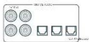
SAT, PVR, BD, CD, STB, AV
01
2AV41)
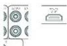
22HDM1-
哈尔拉托 克利阿莫 克鲁

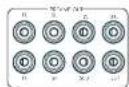
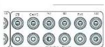
STB, GAME, AV, BD, PVR, CD
中
前用AUX

AUX 3.5mm
前用期日托上
35mm 35mm 35mm 35mm 35mm 35mm 35mm 35mm 35mm 35mm 35mm 35mm 35mm 35mm 35mm 35mm 35mm 35mm 35mm 35mm 35mm 35mm 35mm 35mm 35mm 35mm
Z2 IR (AVR21, AVR31, AV41)
2012年1月29日中
相:求天机的IR默是部无主神志到
$ echo "The command's menu is: 42,0123456789";
$ echo "This command is a random number list".
中
中
甲
M 1
#
L. 10.3.4.5.6.7.8.9.10.11.12.13.14.15.16.17.18.19.20.21.22.23.24.25.26.27.28.29.30.31.32.33.34.35.36.37.38.39.40.41.42.43.44.45.46.47.48.49.50.51.52.53.54.55.56.57.58.59.60.61.62.63.64.65.66.67.68.69.70.71.72.73.74.75.76.77.78.79.80.81.82.83.84.85.86.87.88.89.90.91.92.93.94.95.96.97.98.99.100
T
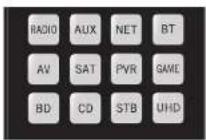
歌樂樂樂樂樂樂樂樂樂樂樂樂樂樂樂樂樂樂樂樂樂樂樂樂樂樂樂樂樂樂樂樂樂樂樂樂樂樂樂樂樂樂樂樂樂樂樂樂樂樂樂樂樂樂樂樂樂樂樂樂樂樂樂樂樂樂樂樂樂樂樂樂樂樂樂樂樂樂
舍地
| 명목 | 요这部分 |
| AMP+ | 선류 기재 썸명목지poons |
| AMP+ | 선류 기재 썸명목지poons |
| AMP+OK | 고수 힘명목지poons |
| AMP+ | HDM 힘명목지,1,2,3,4,5,6,7,8,9,10,11,12,13,14,15,16,17,18,19,20,21,22,23,24,25,26,27,28,29,30,31,32,33,34,35,36,37,38,39,40,41,42,43,44,45,46,47,48,49,50,51,52,53,54,55,56,57,58,59,60,61,62,63,64,65,66,67,68,69,70,71,72,73,74,75,76,77,78,79,80,81,82,83,84,85,86,87,88,89,90,91,92,93,94,95,96,97,98,99,100,101,102,103,104,105,106,107,108,109,110,111,112,113,114,115,116,117,118,119,120,121,122,123,124,125,126,127,128,129,130,131,132,133,134,135,136,137,138,139,140,141,142,143,144,145,146,147,148,149,150,151,152,153,154,155,156,157,158,159,160,161,162,163,164,165,166,167,168,169,170,171,172,173,174,175,176,177,178,179,180,181,182,183,184,185,186,187,188,189,190,191,192,193,194,195,196,197,198,199,200,201,202,203,204,205,206,207,208,209,210,211,212,213,214,215,216,217,218,219,220,221,222,223,224,225,226,227,228,229,230,231,232,233,234,235,236,237,238,239,240,241,242,243,244,245,246,247,248,249,250,251,252,253,254,255,256,257,258,259,260,261,262,263,264,265,266,267,268,269,270,271,272,273,274,275,276,277,278,279,280,281,282,283,284,285,286,287,288,289,290,291,292,293,294,295,296,297,298,299,300,301,302,303,304,305,306,307,308,309,310,311,312,313,314,315,316,317,318,319,320,321,322,323,324,325,326,327,328,329,330,331,332,333,334,335,336,337,338,339,340,341,342,343,344,345,346,347,348,349,350,351,352,353,354,355,356,357,358,359,360,361,362,363,364,365,366,367,368,369,370,371,372,373,374,375,376,377,378,379,380,381,382,383,384,385,386,387,388,389,390,391,392,393,394,395,396,397,398,399,400,401,402,403,404,405,406,407,408,409,410,411,412,413,414,415,416,417,418,419,420,421,422,423,424,425,426,427,428,429,430,431,432,433,434,435,436,437,438,439,440,441,442,443,444,445,446,447,448,449,450,451,452,453,454,455,456,457,458,459,460,461,462,463,464,465,466,467,468,469,470,471,472,473,474,475,476,477,478,479,480,481,482,483,484,485,486,487,488,489,490,491,492,493,494,495,496,497,498,499,500,501,502,503,504,505,506,507,508,509,510,511,512,513,514,515,516,517,518,519,520,521,522,523,524,525,526,527,528,529,530,531,532,533,534,535,536,537,538,539,540,541,542,543,544,545,546,547,548,549,550,551,552,553,554,555,556,557,558,559,560,561,562,563,564,565,566,567,568,569,570,571,572,573,574,575,576,577,578,579,580,581,582,583,584,585,586,587,588,589,590,591,592,593,594,595,596,597,598,599,600,601,602,603,604,605,606,607,608,609,610,611,612,613,614,615,616,617,618,619,620,621,622,623,624,625,626,627,628,629,630,631,632,633,634,635,636,637,638,639,640,641,642,643,644,645,646,647,648,649,650,651,652,653,654,655,656,657,658,659,660,661,662,663,664,665,666,667,668,669,670,671,672,673,674,675,676,677,678,679,680,681,682,683,684,685,686,687,688,689,690,691,692,693,694,695,696,697,698,699,700,701,702,703,704,705,706,707,708,709,710,711,712,713,714,715,716,717,718,719,720,721,722,723,724,725,726,727,728,729,730,731,732,733,734,735,736,737,738,739,740,741,742,743,744,745,746,747,748,749,750,751,752,753,754,755,756,757,758,759,760,761,762,763,764,765,766,767,768,769,770,771,772,773,774,775,776,777,778,779,780,781,782,783,784,785,786,787,788,789,790,791,792,793,794,795,796,797,798,799,800,801,802,803,804,805,806,807,808,809,810,811,812,813,814,815,816,817,818,819,820,821,822,823,824,825,826,827,828,829,830,831,832,833,834,835,836,837,838,839,840,841,842,843,844,845,846,847,848,849,850,851,852,853,854,855,856,857,858,859,860,861,862,863,864,865,866,867,868,869,870,871,872,873,874,875,876,877,878,879,880,881,882,883,884,885,886,887,888,889,890,891,892,893,894,895,896,897,898,899,900,901,902,903,904,905,906,907,908,909,910,911,912,913,914,915,916,917,918,919,920,921,922,923,924,925,926,927,928,929,930,931,932,933,934,935,936,937,938,939,940,941,942,943,944,945,946,947,948,949,950,951,952,953,954,955,956,957,958,959,960,961,962,963,964,965,966,967,968,969,970、 |
中國長垣九台山
LIOI 1
月樂樂樂樂樂樂樂樂樂樂樂樂樂樂樂樂樂樂樂樂樂樂樂樂樂樂樂樂樂樂樂樂樂樂樂樂樂樂樂樂樂樂樂樂樂樂樂樂樂樂樂樂樂樂樂樂樂樂樂樂樂樂樂樂樂樂樂樂樂樂樂樂樂樂樂樂樂樂樂樂樂樂樂樂樂乐
人
默默默默默默默默默默默默默默默默默默默默默默默默默默默默默默默默默默默默默默默默默默默默
□□:中中中中中中中中中中中中中中中中中中中中中中中中中中中中中中中中中中中中中中中中中中中中中中中中中中中中中中中中中中中中中中中中中中中中中中中中中中中中中中中
:SfFJ 1000
月 电
134-
1516-
13.14.15.1601A
67A 1000000000000000000000000000000000000000000000000000000000
日 1234567890
Chromecast built-in serial
京航
3.5
★
GoogleHomee


| Dolby Digital Sosstong | |
| Dolby Digital S.1 | Dolby Digital S.1 Sosstos = 썼사, 썼사, 썼사, 썼사, 썼사, 썼사, 썼사, 썼사, 썼사, 썼사, 썼사, 썼사, 썼사, 썼사, 썼사, 썼사, 썼사, 썼사, 썼사, 썼사, 썼사, 5개의 기재상품만 썼사에 투류고 썼사에 투류고 썼사에 투류고 썼사에 투류고 썼사에 투류고 썼사에 투류고 썼사에 투류고 썼사에 투류고 썼사에 투류고 썼사에 투류고 썼사에 투류ious 5개의 기재상품만 썼사에 투류고 썼사에 투류고 썼사에 투류고 썼사에 투류고 썼사에 투류고 썼사에 투류고 썼사에 투류ious 5개의 기재상품만 썼사에 투류고 썼사에 투류고 5개의 기재상품만 썼사에 투류고 5개의 기재상품만 썼사에 투류고 5개의 기재상품만 썼사에 투류고 5개의 기재상품만 썼사에 투류고 5개의 기재상품만 썼사에 투류고 5개의 기재상품만 썼사, 5개의 기재상품만 썼사, 5개의 기재상품만 썼사, 5개의 기재상품만 썼사, 5개의 기재상품만 썼사, 5개의 기재상품만 썼사, 5개의 기재상품만 썼사, 5개의 기재상품만 썼사, 5개의 기재상품만 5개의 기재상품만 5개의 기재상품만 5개의 기재상품만 5개의 기재상품만 5개의 기재상품만 5개의 기재상품만 5개의 기재상품만 5개의 기재상품만 5개의 기재상품만 5개의 기재상품만 5개의 기재상품만 4개의 기재상품만 4개의 기재상품만 4개의 기재상품만 4개의 기재상품만 4개의 기재상품만 4개의 기재상품만 4개의 기재상품만 4개의 기재상품만 4개의 기재상품만 4개의 기재상품만 4개의 기재상품만 4oke's 50% 4oke's 60% 4oke's 70% 4oke's 80% 4oke's 90% 4oke's 100% 4oke's 110% 4oke's 120% 4oke's 130% 4oke's 140% 4oke's 150% 4oke's 160% 4oke's 170% 4oke's 180% 4oke's 190% 4oke's 200% 4oke's 210% 4oke's 220% 4oke's 230% 4oke's 240% 4oke's 250% 4oke's 260% 4oke's 270% 4oke's 280% 4oke's 290% 4oke's 300% 4oke's 310% 4oke's 320% 4oke's 330% 4oke's 340% 4oke's 350% 4oke's 360% 4oke's 370% 4oke's 380% 4oke's 390% 4oke's 400% 4oke's 410% 4oke's 420% 4oke's 430% 4oke's 440% 4oke's 450% 4oke's 460% 4oke's 470% 4oke's 480% 4oke's 490% 4oke's 500% 4oke's 510% 4oke's 520% 4oke's 530% 4oke's 540% 4oke's 550% 4oke's 560% 4oke's 570% 4oke's 580% 4oke's 590% 4oke's 600% 4oke's 610% 4oke's 620% 4oke's 630% 4oke's 640% 4oke's 650% 4oke's 660% 4oke's 670% 4oke's 680% 4oke's 690% 4oke's 700% 4oke's 710% 4oke's 720% 4oke's 730% 4oke's 740% 4oke's 750% 4oke's 760% 4oke's 770% 4oke's 780% 4oke's 790% 4oke's 800% 4oke's 810% 4oke's 820% 4oke's 830% 4oke's 840% 4oke's 850% 4oke's 860% 4oke's 870% 4oke's 880% 4oke's 890% 4oke's 900% 4oke's 910% 4oke's 920% 4oke's 930% 4oke's 940% 4oke's 950% 4oke's 960% 4oke's 970% 4oke's 980% 4oke's 990% 4oke's 1000% 4oke's 1010% 4oke's 1020% 4oke's 1030% 4oke's 1040% 4oke's 1050% 4oke's 1060% 4oke's 1070% 4oke's 1080% 4oke's 1090% 4oke's 1100% 4oke's 1110% 4oke's 1120% 4oke's 1130% 4oke's 1140% 4oke's 1150% 4oke's 1160% 4oke's 1170% 4oke's 1180% 4oke's 1190% 4oke's 1200% 4oke's 1210% 4oke's 1220% 4oke's 1230% 4oke's 1240% 4oke's 1250% 4oke's 1260% 4oke's 1270% 4oke's 1280% 4oke's 1290% 4oke's 1300% 4oke's 1310% 4oke's 1320% 4oke's 1330% 4oke's 1340% 4oke's 1350% 4oke's 1360% 4oke's 1370% 4oke's 1380% 4oke's 1390% 4oke's 1400% 4oke's 1410% 4oke's 1420% 4oke's 1430% 4oke's 1440% 4oke's 1450% 4oke's 1460% 4oke's 1470% 4oke's 1480% 4oke's 1490% 4oke's 1500% 4oke's 1510% 4oke's 1520% 4oke's 1530% 4oke's 1540% 4oke's 1550% 4oke's 1560% 4oke's 1570% 4oke's 1580% 4oke's 1590% 4oke's 1600% 4oke's 1610% 4oke's 1620% 4oke's 1630% 4oke's 1640% 4oke's 1650% 4oke's 1660% 4oke's 1670% 4oke's 1680% 4oke's 1690% 4oke's 1700% 4oke's 1710% 4oke's 1720% 4oke's 1730% 4oke's 1740% 4oke's 1750% 4oke's 1760% 4oke's 1770% 4oke's 1780% 4oke's 1790% 4oke's 1800% 4oke's 1810% 4oke's 1820% 4oke's 1830% 4oke's 1840% 4oke's 1850% 4oke's 1860% 4oke's 1870% 4oke's 1880% 4oke's 1890% 4oke's 1900% 4oke's 1910% 4oke's 1920% 4oke's 1930% 4oke's 1940% 4oke's 1950% 4oke's 1960% 4oke's 1970% 4oke's 1980% 4oke's 1990% 4oke's 2000% 4oke's 2010% 4oke's 2020% 4oke's 2030% 4oke's 2040% 4oke's 2050% 4oke's 2060% 4oke's 2070% 4oke's 2080% 4oke's 2090% 4oke's 2100% 4oke's 2110% 4oke's 2120% 4oke's 2130% 4oke's 2140% 4oke's 2150% 4oke's 2160% 4oke's 2170% 4oke's 2180% 4oke's 2190% 4oke's 2200% 4oke's 2210% 4oke's 2220% 4oke's 2230% 4oke's 2240% 4oke's 2250% 4oke's 2260% 4oke's 2270% 4oke's 2280% 4oke's 2290% 4oke's 2300% 4oke's 2310% 4oke's 2320% 4oke's 2330% 4oke's 2340% 4oke's 2350% 4oke's 2360% 4oke's 2370% 4oke's 2380% 4oke's 2390% 4oke's 2400% 4oke's 2410% 4oke's 2420% 4oke's 2430% 4oke's 2440% 4oke's 2450% 4oke's 2460% 4oke's 2470% 4oke's 2480% 4oke's 2490% 4oke's 2500% 4oke's 2510% 4oke's 2520% 4oke's 2530% 4oke's 2540% 4oke's 2550% 4oke's 2560% 4oke's 2570% 4oke's 2580% 4oke's 2590% 4oke's 2600% 4oke's 2610% 4oke's 2620% 4oke's 2630% 4oke's 2640% 4oke's 2650% 4oke's 2660% 4oke's 2670% 4oke's 2680% 4oke's 2690% 4oke's 2700% 4oke's 2710% 4oke's 2720% 4oke's 2730% 4oke's 2740% 4oke's 2750% 4oke's 2760% 4oke's 2770% 4oke's 2780% 4oke's 2790% 4oke's 2800% 4oke's 2810% 4oke's 2820% 4oke's 2830% 4oke's 2840% 4oke's 2850% 4oke's 2860% 4oke's 2870% 4oke's 2880% 4oke's 2890% 4oke's 2900% 4oke's 2910% 4oke's 2920% 4oke's 2930% 4oke's 2940% 4oke's 2950% 4oke's 2960% 4oke's 2970% 4oke's 2980% 4oke's 2990% 4oke's 3000% 4oke's 3010% 4oke's 3020% 4oke's 3030% 4oke's 3040% 4oke's 3050% 4oke's 3060% 4oke's 3070% 4oke's 3080% 4oke's 3090% 4oke's 3100% 4oke's 3110% 4oke's 3120% 4oke's 3130% 4oke's 3140% 4oke's 3150% 4oke's 3160% 4oke's 3170% 4oke's 3180% 4oke's 3190% 4oke's 3200% 4oke's 3210% 4oke's 3220% 4oke's 3230% 4oke's 3240% 4oke's 3250% 4oke's 3260% 4oke's 3270% 4oke's 3280% 4oke's 3290% 4oke's 3300% 4oke's 3310% 4oke's 3320% 4oke's 3330% 4oke's 3340% 4oke's 3350% 4oke's 3360% 4oke's 3370% 4oke's 3380% 4oke's 3390% 4oke's 3400% 4oke's 3410% 4oke's 3420% 4oke's 3430% 4oke's 3440% 4oke's 3450% 4oke's 3460% 4oke's 3470% 4oke's 3480% 4oke's 3490% 4oke's 3500% 4oke's 3510% 4oke's 3520% 4oke's 3530% 4oke's 3540% 4oke's 3550% 4oke's 3560% 4oke's 3570% 4oke's 3580% 4oke's 3590% 4oke's 3600% 4oke's 3610% 4oke's 3620% 4oke's 3630% 4oke's 3640% 4oke's 3650% 4oke's 3660% 4oke's 3670% 4oke's 3680% 4oke's 3690% 4oke's 3700% 4oke's 3710% 4oke's 3720% 4oke's 3730% 4oke's 3740% 4oke's 3750% 4oke's 3760% 4oke's 3770% 4oke's 3780% 4oke's 3790% 4oke's 3800% 4oke's 3810% 4oke's 3820% 4oke's 3830% 4oke's 3840% 4oke's 3850% 4oke's 3860% 4oke's 3870% 4oke's 3880% 4oke's 3890% 4oke's 3900% 4oke's 3910% 4oke's 3920% 4oke's 3930% 4oke's 3940% 4oke's 3950% 4oke's 3960% 4oke's 3970% 4oke's 3980% 4oke's 3990% 4oke's 4000% 4oke's 4010% 4oke's 4020% 4oke's 4030% 4oke's 4040% 4oke's 4050% 4oke's 4060% 4oke's 4070% 4oke's 4080% 4oke's 4090% 4oke's 4100% 4oke's 4110% 4oke's 4120% 4oke's 4130% 4oke's 4140% 4oke's 4150% 4oke's 4160% 4oke's 4170% 4oke's 4180% 4oke's 4190% 4oke's 4200% 4oke's 4210% 4oke's 4220% 4oke's 4230% 4oke's 4240% 4oke's 4250% 4oke's 4260% 4oke's 4270% 4oke's 4280% 4oke's 4290% 4oke's 4300% 4oke's 4310% 4oke's 4320% 4oke's 4330% 4oke's 4340% 4oke's 4350% 4oke's 4360% 4oke's 4370% 4oke's 4380% 4oke's 4390% 4oke's 4400% 4oke's 4410% 4oke's 4420% 4oke's 4430% 4oke's 4440% 4oke's 4450% 4oke's 4460% 4oke's 4470% 4oke's 4480% 4oke's 4490% 4oke's 4500% 4oke's 4510% 4oke's 4520% 4oke's 4530% 4oke's 4540% 4oke's 4550% 4oke's 4560% 4oke's 4570% 4oke's 4580% 4oke's 4590% 4oke's 4600% 4oke's 4610% 4oke's 4620% 4oke's 4630% 4oke's 4640% 4oke's 4650% 4oke's 4660% 4oke's 4670% 4oke's 4680% 4oke's 4690% 4oke's 4700% 4oke's 4710% 4oke's 4720% 4oke's 4730% 4oke's 4740% 4oke's 4750% 4oke's 4760% 4oke's 4770% 4oke's 4780% 4oke's 4790% 4oke's 4800% 4oke's 4810% 4oke's 4820% 4oke's 4830% 4oke's 4840% 4oke's 4850% 4oke's 4860% 4oke's 4870% 4oke's 4880% 4oke's 4890% 4oke's 4900% 4oke's 4910% 4oke's 4920% 4oke's 4930% 4oke's 4940% 4oke's 4950% 4oke's 4960% 4oke's 4970% 4oke's 4980% 4oke's 4990% 4oke's 5000% 4oke's 5010% 4oke's 5020% 4oke's 5030% 4oke's 5040% 4oke's 5050% 4oke's 5060% 4oke's 5070% 4oke's 5080% 4oke's 5090% 4oke's 5100% 4oke's 5110% 4oke's 5120% 4oke's 5130% 4oke's 5140% 4oke's 5150% 4oke's 5160% 4oke's 5170% 4oke's 5180% 4oke's 5190% 4oke's 5200% 4oke's 5210% 4oke's 5220% 4oke's 5230% 4oke's 5240% 4oke's 5250% 4oke's 5260% 4oke's 5270% 4oke's 5280% 4oke's 5290% 4oke's 5300% 4oke's 5310% 4oke's 5320% 4oke's 5330% 4oke's 5340% 4oke's 5350% 4oke's 5360% 4oke's 5370% 4oke's 5380% 4oke's 5390% 4oke's 5400% 4oke's 5410% 4oke's 5420% 4oke's 5430% 4oke's 5440% 4oke's 5450% 4oke's 5460% 4oke's 5470% 4oke's 5480% 4oke's 5490% 4oke's 5500% 4oke's 5510% 4oke's 5520% 4oke's 5530% 4oke's 5540% 4oke's 5550% 4oke's 5560% 4oke's 5570% 4oke's 5580% 4oke's 5590% 4oke's 5600% 4oke's 5610% 4oke's 5620% 4oke's 5630% 4oke's 5640% 4oke's 5650% 4oke's 5660% 4oke's 5670% 4oke's 5680% 4oke's 5690% 4oke's 5700% 4oke's 5710% 4oke's 5720% 4oke's 5730% 4oke's 5740% 4oke's 5750% 4oke's 5760% 4oke's 5770% 4oke's 5780% 4oke's 5790% 4oke's 5800% 4oke's 5810% 4oke's 5820% 4oke's 5830% 4oke's 5840% 4oke's 5850% 4oke's 5860% 4oke's 5870% 4oke's 5880% 4oke's 5890% 4oke's 5900% 4oke's 5910% 4oke's 5920% 4oke's 5930% 4oke's 5940% 4oke's 5950% 4oke's 5960% 4oke's 5970% 4oke's 5980% 4oke's 5990% 4oke's 6000% 4oke's 6010% 4oke's 6020% 4oke's 6030% 4oke's 6040% 4oke's 6050% 4oke's 6060% 4oke's 6070% 4oke's 6080% 4oke's 6090% 4oke's 6100% 4oke's 6110% 4oke's 6120% 4oke's 6130% 4oke's 6140% 4oke's 6150% 4oke's 6160% 4oke's 6170% 4oke's 6180% 4oke's 6190% 4oke's 6200% 4oke's 6210% 4oke's 6220% 4oke's 6230% 4oke's 6240% 4oke's 6250% 4oke's 6260% 4oke's 6270% 4oke's 6280% 4oke's 6290% 4oke's 6300% 4oke's 6310% 4oke's 6320% 4oke's 6330% 4oke's 6340% 4oke's 6350% 4oke's 6360% 4oke's 6370% 4oke's 6380% 4oke's 6390% 4oke's 6400% 4oke's 6410% 4oke's 6420% 4oke's 6430% 4oke's 6440% 4oke's 6450% 4oke's 6460% 4oke's 6470% 4oke's 6480% 4oke's 6490% 4oke's 6500% 4oke's 6510% 4oke's 6520% 4oke's 6530% 4oke's 6540% 4oke's 6550% 4oke's 6560% 4oke's 6570% 4oke's 6580% 4oke's 6590% 4oke's 6600% 4oke's 6610% 4oke's 6620% 4oke's 6630% 4oke's 6640% 4oke's 6650% 4oke's 6660% 4oke's 6670% 4oke's 6680% 4oke's 6690% 4oke's 6700% 4oke's 6710% 4oke's 6720% 4oke's 6730% 4oke's 6740% 4oke's 6750% 4oke's 6760% 4oke's 6770% 4oke's 6780% 4oke's 6790% 4oke's 6800% 4oke's 6810% 4oke's 6820% 4oke's 6830% 4oke's 6840% 4oke's 6850% 4oke's 6860% 4oke's 6870% 4oke's 6880% 4oke's 6890% 4oke's 6900% 4oke's 6910% 4oke's 6920% 4oke's 6930% 4oke's 6940% 4oke's 6950% 4oke's 6960% 4oke's 6970% 4oke's 6980% 4oke's 6990% 4oke's 7000% 4oke's 7010% 4oke's 7020% 4oke's 7030% 4oke's 7040% 4oke's 7050% 4oke's 7060% 4oke's 7070% 4oke's 7080% 4oke's 7090% 4oke's 7100% 4oke's 7110% 4oke's 7120% 4oke's 7130% 4oke's 7140% 4oke's 7150% 4oke's 7160% 4oke's 7170% 4oke's 7180% 4oke's 7190% 4oke's 7200% 4oke's 7210% 4oke's 7220% 4oke's 7230% 4oke's 7240% 4oke's 7250% 4oke's 7260% 4oke's 7270% 4oke's 7280% 4oke's 7290% 4oke's 7300% 4oke's 7310% 4oke's 7320% 4oke's 7330% 4oke's 7340% 4oke's 7350% 4oke's 7360% 4oke's 7370% 4oke's 7380% 4oke's 7390% 4oke's 7400% 4oke's 7410% 4oke's 7420% 4oke's 7430% 4oke's 7440% 4oke's 7450% 4oke's 7460% 4oke's 7470% 4oke's 7480% 4oke's 7490% 4oke's 7500% 4oke's 7510% 4oke's 7520% 4oke's 7530% 4oke's 7540% 4oke's 7550% 4oke's 7560% 4oke's 7570% 4oke's 7580% 4oke's 7590% 4oke's 7600% 4oke's 7610% 4oke's 7620% 4oke's 7630% 4oke's 7640% 4oke's 7650% 4oke's 7660% 4oke's 7670% 4oke's 7680% 4oke's 7690% 4oke's 7700% 4oke's 7710% 4oke's 7720% 4oke's 7730% 4oke's 7740% 4oke's 7750% 4oke's 7760% 4oke's 7770% 4oke's 7780% 4oke's 7790% 4oke's 7800% 4oke's 7810% 4oke's 7820% 4oke's 7830% 4oke's 7840% 4oke's 7850% 4oke's 7860% 4oke's 7870% 4oke's 7880% 4oke's 7890% 4oke's 7900% 4oke's 7910% 4oke's 7920% 4oke's 7930% 4oke's 7940% 4oke's 7950% 4oke's 7960% 4oke's 7970% 4oke's 7980% 4oke's 7990% 4oke's 8000% 8010% 8020% 8030% 8040% 8050% 8060% 8070% 8080% 8090% 8100% 8110% 8120% 8130% 8140% 8150% 8160% 8170% 8180% 8190% 8200% 8210% 8220% 8230% 8240% 8250% 8260% 8270% 8280% 8290% 8300% 8310% 8320% 8330% 8340% 8350% 8360% 8370% 8380% 8390% 8400% 8410% 8420% 8430% 8440% 8450% 8460% 8470% 8480% 8490% 8500% 8510% 8520% 8530% 8540% 8550% 8560% 8570% 8580% 8590% 8600% 8610% 8620% 8630% 8640% 8650% 8660% 8670% 8680% 8690% 8700% 8710% 8720% 8730% 8740% 8750% 8760% 8770% 8780% 8790% 8800% 8810% 8820% 8830% 8840% 8850% 8860% 8870% 8880% 8890% 8900% 8910% 8920% 8930% 8940% 8950% 8960% 8970% 8980% 8990% 8100% 8110% 8120% 8130% 8140% 8150% 8160% 8170% 8180% 8190% 8200% 8210% 8220% 8230% 8240% 8250% 8260% 8270% 8280% 8300% 8310% 8320% 8330% 8340% 8350% 8360% 8370% 8380% 8390% 8400% 8410% 8420% 8430% 8440% 8450% 8460% 8470% 8480% 8489% 8500% 8510% 8520% 8530% 8540% 8550% 8560% 8570% 8580% 8590% 8600% 8610% 8620% 8630% 8640% 8650% 8660% 8670% 8680% 869 |
异尼
中 电
H
中
Luxurysupport@harman.com Arcin-
怎能有息或身如?
Aram 1
二、欧拉在粤
| Brix | 55 |
| Deprui | 15 |
| Fucaricau | 15 |
| Gini 555 | |
| Savvi | 60 |
| X# Salarie Ratio | $15 |
| Alfa A27/380/09/09 | |
| Alfa A27 | 133 104 106 08 |
| 132 140 152 06 | |
| 210 245 295 20 | |
| 251 275 299 280 | |
| 257 407 404 0 | |
| Akita Kss | |
| Akita | 064 024 235 103 |
| 171 127 107 10 | |
| 428 430 431 | |
| Aihk | 665 624 258 076 |
| 128 127 162 72 | |
| 222 219 230 261 | |
| 327 407 409 | |
| Aikin | 266 |
| Aihkar | 100 251 |
| Aihk | 250 |
| Amhaz | 075 074 123 171 |
| 245 249 179 407 | |
| 401 | |
| Anem | 280 |
| Ansonsson | 125 |
| Anetoch | 108 185 218 251 |
| 207 277 240 | |
| Anisim | 108 |
| Anileuro | 061 |
| Aix | 016 |
| Arc Enel | 173 175 |
| Arciel | 685 085 285 |
| Arden 1085 250 | |
| Arcena 137 250 | |
| Arcigo 250 | |
| Arcista | 109 111 119 122 |
| 230 | |
| As | 087 101 165 234 |
| Archong | 181 267 |
| Avon | 71 410 |
| Azamonti | 108 |
| Arcia 141 | |
| Arbistic | 081 197 |
| Arbistic | 046 060 056 129 |
| 110 159 164 71 | |
| 185 218 270 763 | |
| 261 249 | |
| Arcia | 150 171 219 |
| Arcix | 123 158 158 165 |
| 157 459 462 | |
| Asia | 106 |
| Aviation | 17 |
| Asylum 109 | |
| Biald | 052 168 |
| Benz B/Global | 204 259 |
| Boline Line 233 108 | |
| 310 396 277 | |
| Bour | 056 043 045 074 |
| 222 036 037 06 | |
| 111 131 132 32 | |
| 158 171 211 212 | |
| 216 217 233 295 | |
| 255 286 108 414 | |
| Bayoncic 110 | |
| Benois 049 085 086 380 | |
| 128 117 100 05 | |
| 229 291 255 263 | |
| 256 | |
| Bestan | 108 116 246 |
| Best 282 | |
| Bestar | 086 086 246 |
| Bacc Diamond | 120 249 |
| Bacc Farcher | 185 |
| Europa 01/02 352 | 026 097 |
| Deutschland | 009 119 275 756 |
| Blue Sky | 109 172 249 200 |
| Bürosat | 264 278 282 289 |
| Brasil | 407 |
| Brasiliania | 063 108 |
| Burman | 262 |
| Burmanias | 163 |
| Ecuador | 419 |
| Euribas | 173 179 129 198 |
| Estonia | 270 |
| Belgium 204 745 | |
| Brickwallia RAS | |
| Brother | 410 |
| Brutto | 264 |
| Brin | 144 747 |
| Bumali 001 069 093 | |
| Cayman | 118 115 121 125 |
| Cape | 176 144 202 245 |
| Cape Verde | 246 262 262 285 |
| Chilean | 286 287 289 314 |
| China | 407 402 |
| Camper | 260 |
| Carlo | 301 310 311 312 |
| Cantabria | 115 118 |
| Congo 165 244 290 | |
| Congo | 020 039 108 264 |
| Cle | 026 094 108 166 |
| Cmeel | 176 171 |
| Cmeel | 272 |
| Cmeel | 251 294 297 |
| Cantonio | 191 252 258 |
| Catalonia | 026 271 198 170 |
| Catalonia | 165 171 189 187 |
| Catalonia | 165 171 189 187 |
| Catalonia | 262 252 258 299 |
| Catalonia | 262 407 409 410 |
| Condo | 108 169 149 171 |
| Condo | 225 255 252 267 |
| Condo | 418 |
| Corso | 219 |
| Corso | 225 |
| Corso | 171 277 |
| Corso 250 262 | |
| Concordato 1/2 | |
| Concordato 1/2 | 172 173 179 198 |
| Corona | 108 |
| Cruyau | 146 166 221 267 |
| Crown | 263 085 086 000 |
| Davon | 108 144 171 135 |
| Davon | 245 255 255 265 |
| Davon | 261 257 277 282 |
| Davon | 262 407 409 418 |
| Co-Edificios | 264 159 153 |
| Culic | 111 363 |
| Dolomieau | 108 607 |
| Darracon | 108 120 117 170 |
| Darrac | 219 410 |
| Darracon | 044 250 |
| Duytke | 194 |
| Doyenact | 134 |
| Dovaca | 011 060 069 108 |
| Dovaca | 129 125 101 196 |
| Delaware | 49 457 |
| Denmark | 004 172 282 403 |
| Desmont | 108 |
| Duyin-27 |
| Duluzion 225 |
| Dugan 331 |
| Dugie 187 |
| Dunys 602 |
| Dimash 219 230 304 208 |
| 150 |
| Ghoshmari 132 |
| Udoes 108 |
| Dual 108 123 127 158 |
| 233,243,248,249 |
| 550,276,285,293 |
| Gumc#r 087 137 105 109 |
| 110,195,204,204,267 |
| Da#dmand 249 287 |
| T#m 164 |
| B# 005 11/20 |
| Edson 1/2 |
| Edson Kinney 1/2 |
| Elbe 08/17 113 120 |
| 44,100,195,203 |
| 229,240,249,259 |
| 407 |
| ELA 108 248 |
| Elu 166 |
| Elu## 109 |
| Elu## Co 250 |
| Elu## 108 119 157 171 |
| 410 |
| Teichmacher 085 108 167 274 |
| 373 |
| Elm 037,042,294,407 |
| 407 |
| Elm 109 |
| Elm 108 167 |
| 410 |
| Hitz 108 171 40 |
| Hipperson 236 130 240 400 |
| 108 |
| 142 |
| Euroline 296 |
| Burschon 108 144,159,160 |
| 61,155 |
| Furzley 424/47 |
| Evelyn 108 16 |
| Ercen#ll 088 |
| Esquilin 108 10 |
| Ferrari 108 171,249,251 |
| 108 |
| Feyssen 032,038,156,162 |
| 192,198,195,203 |
| 201,270 |
| Fibers 108 |
| 192 |
| Finlandia 033,041,105,189 |
| 96 |
| Tirlix 031,066,069,074 |
| 087,102,103,104 |
| 061,107,109,111 |
| 128,140,141,155 |
| 59,161,166,226 |
| 277,294,301,307 |
| 246,259,260,402 |
| 407 |
| Hoffer 031,062,066,158 |
| 1,59,221,233 |
| Hint 275 |
| Four 123,196,246 |
| Formart | 108 109 110 110 |
| 159 239 240 | |
| Fina | 108 243 |
| Hontech | 159 159 166 171 |
| 225 | |
| Futuca Carneria | 083 159 157 247 |
| Furai | 279 264 286 293 |
| 110 | |
| Galest | 198 185 235 265 |
| Galaxy | 255 |
| Galena | 17 |
| Gis. 137 1/2 48 161 | 171 138 162 769 |
| Gev | 179 147 159 166 |
| 411 | |
| Geologic | 064 144 144 143 |
| 164 171 | |
| General | 171 |
| General Electric | 171 |
| Galvanics 182/200 | 171 138 142 200 |
| Goldfish | 249 264 |
| Goldfish | 159 171 |
| Goldfin | 171 |
| Goldstones | 031 063 061 068 |
| 074 138 109 099 | |
| 110 115 120 225 | |
| 185 170 171 266 | |
| 187 194 195 224 | |
| 225 293 293 293 | |
| 264 269 269 270 | |
| 376 385 385 385 | |
| 395 395 395 395 | |
| 157 039 | |
| Greenie | 086 090 108 118 |
| 046 074 086 | |
| Grams 048 413 | 038 |
| Grundstücke | 038 |
| Grund | 188 132 144 141 |
| 145 149 149 156 | |
| 170 242 242 249 | |
| 250 256 256 256 | |
| 418 | |
| Gram X | 081 122 124 147 |
| Gramski 022 022 022 | 081 122 124 147 |
| 033 035 039 041 | |
| 042 043 044 049 | |
| 051 054 057 068 | |
| 052 058 058 068 | |
| 065 073 068 083 | |
| 075 083 079 091 | |
| 105 178 109 111 | |
| 115 128 133 133 | |
| 146 145 156 159 | |
| 162 164 169 171 | |
| 208 212 212 219 | |
| 273 276 316 | |
| Grundlin | 059 273 |
| Ghent Wall 071 080 | 059 273 |
| Grundig 031 063 026 | 073 073 |
| 051 050 054 066 | |
| 052 050 051 066 | |
| 117 133 138 156 | |
| 187 134 137 210 | |
| 232 272 273 287 | |
| 467 | |
| Gk-407 | |
| H&Z 262 | |
| Haber 218 |
| Harmfuls | 069 127 138 |
| 110 126 137 145 | |
| 136 144 149 158 | |
| 157 151 222 225 | |
| 229 218 252 251 | |
| 260 266 299 308 | |
| 402 404 414 | |
| Harmless | 161 |
| Humane | 159 |
| Humana | 297 |
| Hld | 203 |
| Hollister | 172 |
| Hon | 108 158 171 277 |
| 410 | |
| Illness | 173 179 |
| Illam | 054 108 177 224 |
| 24 410 | |
| Hitless | 273 |
| Hilustre | 302 |
| Hit | 204 |
| Hirachei | 022 059 048 08 |
| 029 030 030 089 | |
| 040 041 033 097 | |
| 055 056 057 094 | |
| 108 115 121 126 | |
| 127 128 129 134 | |
| 135 140 147 157 | |
| 156 159 161 178 | |
| 166 169 172 219 | |
| 216 226 239 276 | |
| 229 236 250 255 | |
| 413 415 417 421 | |
| 423 | |
| Illicit | 273 |
| III | 128 195 251 |
| Loher | 059 117 153 246 |
| 250 | |
| Hazard | 204 |
| Hypert. 159 161 173 | 429 |
| Hyster. | 063 069 077 108 |
| 118 152 149 250 | |
| 263 264 293 407 | |
| Iyanda 152 155 160 173 | 317 |
| Injury | 44 |
| Kt | 094 108 159 177 |
| 439 410 | |
| Leak | 291 297 |
| Impure 108 109 113 | 154 165 229 243 |
| 200 200 297 407 | |
| Inkeler | 152 141 147 148 |
| 242 211 273 279 | |
| Ingendil 171 | 37 |
| Inno-IC | 127 139 161 189 |
| 237 215 | |
| Immunosup. 110 | 233 |
| Intemadion | 233 |
| Interleuk. | 067 108 132 134 |
| 137 141 147 154 | |
| 165 179 212 274 | |
| 265 265 355 616 | |
| Intevation | 085 085 108 132 |
| 144 156 171 210 | |
| Inovac | 171 |
| inotit. 117/118/119/120/121/122/123/124/125/126/127/128/129/130/131/132/133/134/135/136/137/138/139/140/141/142/143/144/145/146/147/148/149/150/151/152/153/154/155/156/157/158/159/160/161/162/163/164/165/166/167/168/169/170/171/172/173/174/175/176/177/178/179/180/181/182/183/184/185/186/187/188/189/190/191/192/193/194/195/196/197/198/199/200/201/202/203/204/205/206/207/208/209/210/211/212/213/214/215/216/217/218/219/220/221/222/223/224/225/226/227/228/229/230/231/232/233/234/235/236/237/238/239/240/241/242/243/244/245/246/247/248/249/250/251/252/253/254/255/256/257/258/259/260/261/262/263/264/265/266/267/268/269/270/271/272/273/274/275/276/277/278/279/280/281/282/283/284/285/286/287/288/289/290/291/292/293/294/295/296/297/298/299/300/301/302/303/304/305/306/307/308/309/310/311/312/313/314/315/316/317/318/319/320/321/322/323/324/325/326/327/328/329/330/331/332/333/334/335/336/337/338/339/340/341/342/343/344/345/346/347/348/349/350/351/352/353/354/355/356/357/358/359/360/361/362/363/364/365/366/367/368/369/370/371/372/373/374/375/376/377/378/379/380/381/382/383/384/385/386/387/388/389/390/391/392/393/394/395/396/397/398/399/400/401/402/403/404/405/406/407/408/409/410/411/412/413/414/415/416/417/418/419/420/421/422/423/424/425/426/427/428/429/430/431/432/433/434/435/436/437/438/439/440/441/442/443/444/445/446/447/448/449/450/451/452/453/454/455/456/457/458/459/460/461/462/463/464/465/466/467/468/469/470/471/472/473/474/475/476/477/478/479/480/481/482/483/484/485/486/487/488/489/490/491/492/493/494/495/496/497/498/499/500/501/502/503/504/505/506/507/508/509/510/511/512/513/514/515/516/517/518/519/520/521/522/523/524/525/526/527/528/529/530/531/532/533/534/535/536/537/538/539/540/541/542/543/544/545/546/547/548/549/550/551/552/553/554/555/556/557/558/559/560/561/562/563/564/565/566/567/568/569/570/571/572/573/574/575/576/577/578/579/580/581/582/583/584/585/586/587/588/589/590/591/592/593/594/595/596/597/598/599/600/601/602/603/604/605/606/607/608/609/610/611/612/613/614/615/616/617/618/619/620/621/622/623/624/625/626/627/628/629/630/631/632/633/634/635/636/637/638/639/640/641/642/643/644/645/646/647/648/649/650/651/652/653/654/655/656/657/658/659/660/661/662/663/664/665/666/667/668/669/670/671/672/673/674/675/676/677/678/679/680/681/682/683/684/685/686/687/688/689/690/691/692/693/694/695/696/697/698/699/700/701/702/703/704/705/706/707/708/709/710/711/712/713/714/715/716/717/718/719/720/721/722/723/724/725/726/727/728/729/730/731/732/733/734/735/736/737/738/739/740/741/742/743/744/745/746/747/748/749/750/751/752/753/754/755/756/757/758/759/760/761/762/763/764/765/766/767/768/769/770/771/772/773/774/775/776/777/778/779/780/781/782/783/784/785/786/787/788/789/790/791/792/793/794/795/796/797/798/799/800/801/802/803/804/805/806/807/808/809/810/811/812/813/814/815/816/817/818/819/820/821/822/823/824/825/826/827/828/829/830/831/832/833/834/835/836/837/838/839/840/841/842/843/844/845/846/847/848/849/850/851/852/853/854/855/856/857/858/859/860/861/862/863/864/865/866/867/868/869/870/871/872/873/874/875/876/877/878/879/880/881/882/883/884/885/886/887/888/889/890/891/892/893/894/895/896/897/898/899/900/901/902/903/904/905/906/907/908/909/910/911/912/913/914/915/916/917/918/919/920/921/922/923/924/925/926/927/928/929/930/931/932/933/934/935/936/937/938/939/940/941/942/943/944/945/946/947/948/949/950/951/952/953/954/955/956/957/958/959/960/961/962/963/964/965/966/967/968/969/970/971/972/973/974/975/976/977/978/979/980/981/982/983/984/985/986/987/988/989/990/991/992/993/994/995/996/997/998/999/1000 |
| In. | 081 159 171 709 |
| 410 | |
| m | 041 232 117 152 |
| 124 140 141 144 | |
| 145 147 148 156 | |
| 158 242 211 250 | |
| 268 44 44 45 | |
| Jepuisin 293 | |
| Juno 293 | |
| Joule 069 074 282 | 406 |
| Juc | 120 159 279 709 |
| K.Cesic 107 | |
| Kuda | 136 |
| Kubai | 127 299 273 |
| 380 416 | |
| Kamimorion | 664 410 |
| Kapirch | 080 141 147 148 |
| 101 | |
| Kircher | 041 244 393 109 |
| 117 165 262 273 | |
| 774 281 289 407 | |
| 418 | |
| Kathiric | 187 |
| Kawa | 409 |
| Kindo | 060 108 127 132 |
| 229 246 246 249 | |
| 270 273 255 | |
| Karnady | 140 197 |
| Kernes | 108 249 261 |
| Kaynay | 207 235 |
| Kiton | 246 264 293 |
| Kretzel | 058 108 239 269 |
| 264 273 | |
| Knotting 316 N/A 274 | |
| Kroika 407 | |
| Kronen 416 | |
| Kula-technique | 114 158 233 |
| Laser | 574 |
| Lasser | 115 |
| Longo | 108 110 170 240 |
| 410 | |
| Lanot | 248 264 |
| Lev 426 | |
| Li | 013 214 015 088 |
| 060 050 128 110 | |
| 181 200 253 269 | |
| 280 288 | |
| Liesenkauser | 138 |
| Liees | 061 074 133 118 |
| 127 130 151 146 | |
| 264 292 409 416 | |
| Luee | 046 099 095 131 |
| 138 142 113 151 | |
| 190 204 | |
| Lugli | 070 187 251 |
| Luna | 137 197 229 246 |
| 249 | |
| Luminesen | 329 245 246 100 |
| Luzer | 032 000 004 101 |
| 101 105 115 128 | |
| 133 134 140 148 | |
| 153 156 159 196 | |
| 257 240 245 251 | |
| 267 275 276 229 | |
| M.I.Technik | 163 104 105 100 |
| 127 140 276 | |
| M.I.C. | 074 |
| Macromic | 059 |
| Magnanimy | 168 144 158 161 |
| Magnolium | 185 199 |
| Magnaporchis | 106 |
| Magnusius | 251 |
| Magnus | 651 071 252 253 254 450 |
| Manihotum | 249 254 |
| Manuret 108 | |
| Marmal | 664 |
| Marmal 231 074 779-407 | |
| Manuret | 108 |
| Manuret 205 037 05 | 660 |
| Manuret 205 037 05 | 042 063 069 070 039 096 100 108 116 36 14 159 171 72 16 160 202 219 320 407 409 416 |
| Manur | 749 |
| Manuret 031 407 | |
| Medion | 611 074 138 110 127 132 14 142 29 |
| Manuret 286 | |
| Medion 135 | 152 |
| Medion 037 132 236 387 | |
| Manuret 286 | 100 01 108 218 219 356 564 765 322 525 |
| Minacmox | 074 249 703 764 382 295 |
| Minacmox | 286 |
| Minacmox 097 107 172 233 | |
| Minacmox | 110 047 |
| Minacmox 097 107 172 233 | |
| Minacmox | 081 32 107 204 224 249 |
| Minacmox | 158 191 289 225 259 367 767 |
| Minacmox | 031 229 033 |
| Minacmox | 109 152 299 418 |
| Minacmox | 219 254 |
| Minacmox 250 | |
| ML | 086 131 131 |
| Multicort 241 254 407 | |
| Multicort | 081 225 333 306 199 397 77 189 267 |
| Mucormox 251 | |
| Narbo | 407 |
| Narbo mox | 170 |
| Narbo mox | 137 |
| Neubemann | 037 013 253 393 038 084 096 092 039 01 108 110 119 34 13 137 154 49 664 311 217 76 77 273 233 245 202 51 200 256 374 404 |
| Nox | 664 108 420 |
| Neubemann 105 049 750 | |
| Neubemann 289 | |
| Narbo 108 | |
| Narbo 219 | |
| Narbo 29 264 |
| Nkpa | 108 |
| Nsien | 268 |
| Nakko | 172 232 267 |
| Nagamaii | 172 179 |
| Naka | 602 074 112 135 |
| Ong | 135 170 59 52 |
| Ong | 140 111 13 26 |
| Nadamirele | 158 222 27 27 |
| Nadamirele | 158 222 27 27 |
| Nadamirele | 158 222 27 27 |
| Nanm N | 108 |
| Nanm 249 264 | |
| Nanm | 987 |
| Nanmari | 108 |
| Oromie 332 101 102 137 | |
| Okono | 108 255 |
| Oromie 654 108 109 140 | |
| Opon | 250 |
| Opon | 040 038 139 134 |
| Othier | 989 |
| Oton | 025 025 262 392 |
| Oton | 053 059 069 070 |
| Oton | 074 038 138 138 |
| Oton | 152 135 137 138 |
| Oton | 152 135 137 138 |
| Oton | 235 249 250 251 |
| Oton | 256 407 264 408 |
| Oton 13 262.074 | 10 116 |
| Oronund 219 | 228 228 207 410 |
| Ouaji | 108 |
| Ouaji | 099 060 111 135 |
| Ouaji | 118 |
| Ooi | 090 104 204 282 |
| Oitivand | 076 037 036 045 |
| Oitivand | 076 036 036 045 |
| Oitivand | 076 036 036 045 |
| Oitivand | 121 101 108 109 |
| Oitivand | 111 110 118 119 |
| Oitivand | 121 151 152 159 |
| Oitivand | 136 135 139 140 |
| Oitivand | 136 135 139 140 |
| Oitivand | 163 171 173 185 |
| Oitivand | 163 171 173 185 |
| Oitivand | 202 202 202 211 |
| Pemasiain 148 | 202 215 202 217 |
| Pemasiain 148 | 202 202 202 217 |
| Pemasiain 148 | 202 202 202 217 |
| Pemasiain 148 | 202 202 202 217 |
| Pemasiain 148 | 202 202 202 217 |
| Pemasiain 144 | 144 |
| Pemasiain 144 | 144 |
| Pemasiain 144 | 144 |
| Phillips | 027/038/009/019 |
| 027 021 045/067 | |
| 045 022 138 104 | |
| 111 112 116 119 | |
| 112 113 115 118 | |
| 407 412 | |
| Phyllis | 111 719 222 219 |
| Phoenix 090/108 119 | |
| Pierce | 108 132 198 402 |
| Foster | 987 |
| Ryerson | 656 25% |
| Everpoint | 122 |
| President | 066 029 |
| President Office | 112 104 |
| President | 368 |
| P1923 | |
| P1929 | |
| P1925 | |
| No 201 427 | |
| Prentice 189 171 267 | |
| Poincare 231 108 268 | |
| Poincare 120 185 | |
| Poincare 120 178 299 | |
| 200 229 245 267 | |
| 270 285 286 287 | |
| Pronotal 18 | |
| Pronotal 107 108 2 | 9249 |
| Pronotal 068 108 120 | |
| 287 418 | |
| Pyr. 103 100 31 | |
| Quadrant 120 245 266 | |
| Quadrant 266 277 291 | |
| 245 277 244 266 | |
| 277 266 277 266 | |
| 211 266 204 267 | |
| 195 185 171 153 | |
| 98 165 165 153 | |
| 136 165 136 142 | |
| 141 140 136 131 | |
| 139 131 116 117 | |
| 111 108 105 102 | |
| 100 100 100 100 | |
| 092 090 089 087 | |
| 086 084 072 092 | |
| 059 058 042 020 | |
| 036 027 025 | |
| Rafine 266 267 108 261 | |
| Reference in 108 61 104 | |
| Rafine in 108 104 | |
| Rafine in 108 104 | |
| Rafine in 108 104 | |
| Rafine in 108 104 | |
| Rafine in 108 104 | |
| Rafine in 108 104 | |
| Rafine in 108 105 104 | |
| Rafine in 108 105 104 | |
| Rafine in 108 105 104 | |
| Rafine in 108 105 104 | |
| Rafine in 108 105 104 | |
| Rafine in 108 106 104 | |
| Rafine in 108 106 104 | |
| Rafine in 108 106 104 | |
| Rafine in 108 106 104 | |
| Rafine in 108 106 104 | |
| Rafine in 108 107 104 | |
| Rafine in 108 107 104 | |
| Rafine in 108 107 104 | |
| Rafine in 108 107 104 | |
| Rafine in 108 107 104 | |
| Rafine in 108 108 104 | |
| Rafine in 108 108 104 | |
| Rafine in 108 108 104 | |
| Rafine in 108 108 104 | |
| Rafine in 108 108 104 | |
| Rafine in 108 109 104 | |
| Rafine in 108 109 104 | |
| Rafine in 108 109 104 | |
| Rafine in 108 109 104 | |
| Rafine in 108 109 104 | |
| Rafine in 108 108 104 | |
| Rafine in 108 108 104 | |
| Rafine in 108 108 104 | |
| Rafine in 108 108 104 | |
| Rafine in 108 107 104 | |
| Rafine in 108 107 104 | |
| Rafine in 108 107 104 | |
| Rafine in 108 107 104 | |
| Rafine in 108 106 104 | |
| Rafine in 108 106 104 | |
| Rafine in 108 106 104 | |
| Rafine in 108 106 104 | |
| Rafine in 108 105 104 | |
| Rafine in 108 105 104 | |
| Rafine in 108 105 104 | |
| Rafine in 108 105 104 | |
| Rafine in 108 104 104 | |
| Rafine in 108 104 104 | |
| Rafine in 108 104 104 | |
| Rafine in 108 104 104 | |
| Rafine in 108 104 104 | |
| Rafine in 108 105 104 | |
| Rafine in 108 105 104 | |
| Rafine in 108 105 104 | |
| Rafine in 108 105 104 | |
| Rafine in 108 107 104 | |
| Rafine in 108 107 104 | |
| Rafine in 108 107 104 | |
| Rafine in 108 107 104 | |
| Rafine in 108 109 104 | |
| Rafine in 108 109 104 | |
| Rafine in 108 109 104 | |
| Rafine in 108 109 104 | |
| Rafine in 108 107 104 | |
| Rafine in 108 107 104 | |
| Rafine in 108 107 104 | |
| Rafine in 108 107 104 | |
| Rafine in 108 105 104 | |
| Rafine in 108 105 104 | |
| Rafine in 108 105 104 | |
| Rafine in 108 105 104 | |
| Rafine in 108 108 104 | |
| Rafine in 108 108 104 | |
| Rafine in 108 108 104 | |
| Rafine in 108 108 104 | |
| Rafine in 108 106 104 | |
| Rafine in 108 106 104 | |
| Rafine in 108 106 104 | |
| Rafine in 108 106 104 | |
| Rafine in 108 108 104 | |
| Rafine in 108 108 104 | |
| Rafine in 108 108 104 | |
| Rafine in 108 108 104 | |
| Rafine in 108 105 104 | |
| Rafine in 108 105 104 | |
| Rafine in 108 105 104 | |
| Rafine in 108 105 104 | |
| Rafine in 107 107 104 | |
| Rafine in 107 107 104 | |
| Rafine in 107 107 104 | |
| Rafine in 107 107 104 | |
| Rafine in 107 107 104 | |
| Rafine in 107 108 104 | |
| Rafine in 107 108 104 | |
| Rafine in 107 108 104 | |
| Rafine in 107 108 104 | |
| Rafine in 107 108 104 | |
| Rafine in 107 109 104 | |
| Rafine in 107 109 104 | |
| Rafine in 107 109 104 | |
| Rafine in 107 109 104 | |
| Rafine in 107 109 104 | |
| Rafine in 107 108 104 | |
| Rafine in 107 108 104 | |
| Rafine in 107 108 104 | |
| Rafine in 107 108 104 | |
| Rafine in 107 107 104 | |
| Rafine in 107 107 104 | |
| Rafine in 107 107 104 | |
| Rafine in 107 107 104 | |
| Rafine in 107 106 104 | |
| Rafine in 107 106 104 | |
| Rafine in 107 106 104 | |
| Rafine in 107 106 104 | |
| Rafine in 107 106 104 | |
| Rafine in 107 107 104 | |
| Rafine in 107 107 104 | |
| Rafine in 107 107 104 | |
| Rafine in 107 107 104 | |
| Rafine in 107 109 104 | |
| Rafine in 107 109 104 | |
| Rafine in 107 109 104 | |
| Rafine in 107 109 104 | |
| Rafine in 107 107 104 | |
| Rafine in 107 107 104 | |
| Rafine in 107 107 104 | |
| Rafine in 107 107 104 | |
| Rafine in 107 105 104 | |
| Rafine in 107 105 104 | |
| Rafine in 107 105 104 | |
| Rafine in 107 105 104 | |
| Rafine in 107 105 104 | |
| Rafine in 107 106 104 | |
| Rafine in 107 106 104 | |
| Rafine in 107 106 104 | |
| Rafine in 107 106 104 | |
| Rafine in 107 108 104 | |
| Rafine in 107 108 104 | |
| Rafine in 107 108 104 | |
| Rafine in 107 108 104 | |
| Rafine in 107 106 104 | |
| Rafine in 107 106 104 | |
| Rafine in 107 106 104 | |
| Rafine in 107 106 104 | |
| Rafine in 107 109 104 | |
| Rafine in 107 109 104 | |
| Rafine in 107 109 104 | |
| Rafine in 107 109 104 | |
| Rafine in 107 106 104 | |
| Rafine in 107 106 104 | |
| Rafine in 107 106 104 | |
| Rafine in 107 106 104 | |
| Rafine in 107 105 104 | |
| Rafine in 107 105 104 | |
| Rafine in 107 105 104 | |
| Rafine in 107 106 104 | |
| Rafine in 107 107 104 | |
| Rafine in 107 107 104 | |
| Rafine in 107 108 104 | |
| Rafine in 107 108 104 | |
| Rafine in 107 109 104 | |
| Rafine in 107 109 104 | |
| Rafine in 107 108 104 | |
| Rafine in 107 108 104 | |
| Rafine in 107 109 104 | |
| Rafine in 107 109 104 | |
| Rafine in 107 106 104 | |
| Rafine in 107 106 104 | |
| Rafine in 107 107 104 | |
| Rafine in 107 107 104 | |
| Rafine in 107 108 104 | |
| Rafine in 107 109 104 | |
| Rafine in 107 109 104 | |
| Rafine in 107 108 104 | |
| Rafine in 107 109 104 | |
| Rafine in 107 109 104 | |
| Rafine in 107 108 104 | |
| Rafine in 107 107 104 | |
| Rafine in 107 108 104 | |
| Rafine in 107 109 104 | |
| Rafine in 107 109 104 | |
| Rafine in 107 109 104 | |
| Rafine in 107 108 104 | |
| Rafine in 107 109 104 | |
| Rafine in 107 108 104 | |
| Rafine in 107 109 104 | |
| Rafine in 107 108 104 | |
| Rafine in 107 108 104 | |
| Rafine in 107 109 104 | |
| Rafine in 107 108 104 | |
| Rafine in 107 109 104 | |
| Rafine in 107 109 104 | |
| Rafine in 107 109 104 | |
| Rafine in 107 107 104 | |
| Rafine in 107 108 104 | |
| Rafine in 107 108 104 | |
| Rafine in 107 108 104 | |
| Rafine in 107 109 104 | |
| Rafine in 107 108 104 | |
| Rafine in 107 108 104 | |
| Rafine in 107 108 104 | |
| Rafine in 107 109 104 | |
| Rafine in 107 107 104 | |
| Rafine in 107 108 104 | |
| Rafine in 107 108 104 | |
| Rafine in 107 109 104 | |
| Rafine in 107 108 104 | |
| Rafine in 107 107 104 | |
| Rafine in 107 108 104 | |
| Rafine in 107 108 104 | |
| Rafine in 107 109 104 | |
| Rafine in 107 107 104 | |
| Rafine in 107 109 104 | |
| Rafine in 107 108 104 | |
| Rafine in 107 108 104 | |
| Rafine in 107 109 104 | |
| Rafine in 107 107 104 | |
| Rafine in 107 107 104 | |
| Rafine in 107 108 104 | |
| Rafine in 107 108 104 | |
| Rafine in 107 107 104 | |
| Rafine in 107 108 104 | |
| Rafine in 107 108 104 | |
| Rafine in 107 108 104 | |
| Rafine in 107 107 104 | |
| Rafine in 107 108 104 | |
| Rafine in 107 109 104 | |
| Rafine in 107 108 104 | |
| Rafine in 107 108 104 | |
| Rafine in 107 107 104 | |
| Rafine in 107 108 104 | |
| Rafine in 107 107 104 | |
| Rafine in 107 108 104 | |
| Rafine in 107 108 104 | |
| Rafine in 107 107 104 | |
| Rafine in 107 107 104 | |
| Rafine in 107 108 104 | |
| Rafine in 107 108 104 | |
| Rafine in 107 106 104 | |
| Rafine in 107 108 104 | |
| Rafine in 107 108 104 | |
| Rafine in 107 108 104 | |
| Rafine in 107 109 104 | |
| Rafine in 107 106 104 | |
| Rafine in 107 108 104 | |
| Rafine in 107 108 104 | |
| Rafine in 107 108 104 | |
| Rafine in 107 106 104 | |
| Rafine in 107 108 104 | |
| Rafine in 107 109 104 | |
| Rafine in 107 108 104 | |
| Rafine in 107 108 104 | |
| Rafine in 107 106 104 | |
| Rafine in 107 108 104 | |
| Rafine in 107 106 104 | |
| Rafine in 107 108 104 | |
| Rafine in 107 108 104 | |
| Rafine in 107 106 104 | |
| Rafine in 107 108 104 | |
| Rafine in 107 107 104 | |
| Rafine in 107 108 104 | |
| Rafine in 107 108 104 | |
| Rafine in 107 106 104 | |
| Rafine in 107 106 104 | |
| Rafine in 107 108 104 | |
| Rafine in 107 108 104 | |
| Rafine in 107 106 104 | |
| Rafine in 107 106 104 | |
| Rafine in 107 107 104 | |
| Rafine in 107 108 104 | |
| Rafine in 107 108 104 | |
| Rafine in 107 108 104 | |
| Rafine in 107 106 104 | |
| Rafine in 107 107 104 | |
| Rafine in 107 108 104 | |
| Rafine in 107 108 104 | |
| Rafine in 107 106 104 | |
| Rafine in 107 107 104 | |
| Rafine in 107 106 104 | |
| Rafine in 107 108 104 | |
| Rafine in 107 108 104 | |
| Rafine in 107 106 104 | |
| Rafine in 107 107 104 | |
| Rafine in 107 107 104 | |
| Rafine in 107 108 104 | |
| Rafine in 107 106 104 | |
| Rafine in 107 108 104 | |
| Rafine in 107 108 104 | |
| Rafine in 107 107 104 | |
| Rafine in 107 108 104 | |
| Rafine in 107 106 104 | |
| Rafine in 107 108 104 | |
| Rafine in 107 106 104 | |
| Rafine in 107 107 104 | |
| Rafine in 107 108 104 | |
| Rafine in 107 106 104 | |
| Rafine in 107 108 104 | |
| Rafine in 107 107 104 | |
| Rafine in 107 106 104 | |
| Rafine in 107 108 104 | |
| Rafine in 107 106 104 | |
| Rafine in 107 108 104 | |
| Rafine in 107 106 104 | |
| Rafine in 107 106 104 | |
| Rafine in 107 108 104 | |
| Rafine in 107 106 104 | |
| Rafine in 107 108 104 | |
| Rafine in 107 107 104 | |
| Rafine in 107 107 104 | |
| Rafine in 107 108 104 | |
| Rafine in 107 106 104 | |
| Rafine in 107 107 104 | |
| Rafine in 107 108 104 | |
| Rafine in 107 107 104 | |
| Rafine in 107 108 104 | |
| Rafine in 107 106 104 | |
| Rafine in 107 107 104 | |
| Rafine in 107 106 104 | |
| Rafine in 107 107 104 | |
| Rafine in 107 108 104 | |
| Rafine in 107 106 104 | |
| Rafine in 107 107 104 | |
| Rafine in 107 107 104 | |
| Rafine in 107 106 104 | |
| Rafine in 107 107 104 | |
| Rafine in 107 108 104 | |
| Rafine in 107 107 104 | |
| Rafine in 107 106 104 | |
| Rafine in 107 107 104 | |
| Rafine in 107 108 104 | |
| Rafine in 107 108 104 | |
| Rafine in 107 107 104 | |
| Rafine in 107 106 104 | |
| Rafine in 107 107 104 | |
| Rafine in 107 106 104 | |
| Rafine in 107 107 104 | |
| Rafine in 107 106 104 | |
| Rafine in 107 108 104 | |
| Rafine in 107 107 104 | |
| Rafine in 107 106 104 | |
| Rafine in 107 107 104 | |
| Rafine in 107 107 104 | |
| Rafine in 107 106 104 | |
| Rafine in 107 108 104 | |
| Rafine in 107 107 104 | |
| Rafine in 107 108 104 | |
| Rafine in 107 106 104 | |
| Rafine in 107 106 104 | |
| Rafine in 107 108 104 | |
| Rafine in 107 107 104 | |
| Rafine in 107 106 104 | |
| Rafine in 107 106 104 | |
| Rafine in 107 108 104 | |
| Rafine in 107 107 104 | |
| Rafine in 107 108 104 | |
| Rafine in 107 107 104 | |
| Rafine in 107 106 104 | |
| Rafine in 107 108 104 | |
| Rafine in 107 107 104 | |
| Rafine in 107 107 104 | |
| Rafine in 107 106 104 | |
| Rafine in 107 108 104 | |
| Rafine in 107 106 104 | |
| Rafine in 107 107 104 | |
| Rafine in 107 106 104 | |
| Rafine in 107 106 104 | |
| Rafine in 107 108 104 | |
| Rafine in 107 106 104 | |
| Rafine in 107 106 104 | |
| Rafine in 107 106 104 | |
| Rafine in 107 108 104 | |
| Rafine in 107 106 104 | |
| Rafine in 107 107 104 | |
| Rafine in 107 107 104 | |
| Rafine in 107 107 104 | |
| Rafine in 107 108 104 | |
| Rafine in 107 106 104 | |
| Rafine in 107 106 104 | |
| Rafine in 107 106 104 | |
| Rafine in 107 107 104 | |
| Rafine in 107 106 104 | |
| Rafine in 107 106 104 | |
| Rafine in 107 106 104 | |
| Rafine in 107 108 104 | |
| Rafine in 107 107 104 | |
| Rafine in 107 107 104 | |
| Rafine in 107 107 104 | |
| Rafine in 107 108 104 | |
| Rafine in 107 107 104 | |
| Rafine in 107 108 104 | |
| Rafine in 107 107 104 | |
| Rafine in 107 107 104 | |
| Rafine in 107 108 104 | |
| Rafine in 107 107 104 | |
| Rafine in 107 106 104 | |
| Rafine in 107 106 104 | |
| Rafine in 107 106 104 | |
| Rafine in 107 107 104 | |
| Rafine in 107 108 104 | |
| Rafine in 107 106 104 | |
| Rafine in 107 106 104 | |
| Rafine in 107 107 104 | |
| Rafine in 107 106 104 | |
| Rafine in 107 108 104 | |
| Rafine in 107 106 104 | |
| Rafine in 107 106 104 | |
| Rafine in 107 107 104 | |
| Rafine in 107 107 104 | |
| Rafine in 107 106 104 | |
| Rafine in 107 106 104 | |
| Rafine in 107 108 104 | |
| Rafine in 107 108 104 | |
| Rafine in 107 107,233,235,236,237,238,239,242,243,245,246,252,253,256,257,258,259,262,263,264,265,266,267,268,269,272,273,274,275,276,277,278,279,282,283,284,285,286,287,288,289,292,293,294,295,296,297,298,299,302,303,304,305,306,307,308,309,312,323,324,325,326,327,328,329,332,333,334,335,336,337,338,339,342,343,345,346,347,348,349,352,353,354,355,356,357,358,359,362,363,364,365,366,367,368,369,372,373,374,375,376,377,378,379,382,383,384,385,386,387,388,389,392,393,394,395,396,397,398,399,402,403,404,405,406,407,408,409,412,423,424,425,426,427,428,429,432,433,434,435,436,437,438,439,442,443,444,445,446,447,448,449,452,453,454,455,456,457,458,459,462,463,464,465,466,467,468,469,472,473,474,475,476,477,478,479,482,483,484,485,486,487,488,489,492,493,494,495,496,497,498,499,502,503,504,505,506,507,508,509,512,513,514,515,516,517,518,522,523,524,525,526,527,528,529,532,533,534,535,536,537,538,539,542,543,544,545,546,547,548,549,552,553,554,555,556,557,558,559,562,563,564,565,566,567,568,569,572,573,574,575,576,577,578,579,582,583,584,585,586,587,588,589,592,593,594,595,596,597,598,599,602,603,604,605,606,607,608,609,612,623,624,625,626,627,628,629,632,633,634,635,636,637,638,639,642,643,644,645,646,647,648,649,652,653,654,655,656,657,658,659,662,663,664,665,666,667,668,669,672,673,674,675,676,677,678,679,682,683,684,685,686,687,688,689,692,693,694,695,696,697,698,699,699,699,699,699,699,699,699,699,699,699,699,699,699,699,699,699,699,699,699,699,699,699,699,699,698,699,699,699,699,699,699,699,699,699,699,699,699,699,699,699,699,699,699,699,699,699,699,699,698,698,699,699,699,699,699,699,699,699,699,699,699,699,699,699,699,699,699,699,699,699,699,699,699,695,696,697,698,699,699,699,699,699,699,699,699,699,699,699,699,699,699,699,699,699,699,699,699,698,699,699,699,698,699,699,699,699,699,699,699,699,699,699,699,699,699,699,699,699,699,699,699,699,698,699,699,698,699,699,699,699,699,699,699,699,699,699,699,699,699,699,699,699,699,699,699,699,699,698,699,699,698,698,699,699,699,699,699,699,699,699,699,699,699,699,699,699,699,699,699,699,699,699,698,699,699,695,696,697,698,699,699,699,699,699,699,699,699,699,699,699,699,699,699,699,699,699,699,698,699,699,699,699,699,698,699,699,699,699,699,699,699,698,699,699,699,699,699,698,699,699,698,699,699,698,699,699,698,699,699,698,699,698,699,698,699,698,699,698,699,698,699,698,699,698,699,698,699,698,699,698,699,698,699,698,698,699,698,699,698,699,698,699,698,699,698,699,698,699,698,699,698,699,698,699,698,699,698,699,699,698,699,698,699,698,699,698,699,698,699,698,699,698,699,698,699,698,699,698,699,699,698,699,699,698,699,698,699,698,699,698,699,698,699,698,699,698,699,698,699,698,698,699,698,699,698,699,699,698,699,698,699,698,699,698,699,698,699,698,699,698,699,698,699,698,698,699,698,698,699,698,699,698,699,698,699,698,699,698,699,698,699,698,699,698,699,698,699,698,698,699,698,698,699,698,698,699,698,699,698,699,698,699,698,699,698,699,698,699,698,699,698,699,699,698,699,698,699,698,698,699,698,699,698,699,698,699,698,699,698,699,698,699,698,699,698,699,699,698,699,699,698,699,699,698,699,698,699,698,699,698,699,698,699,698,699,698,699,699,698,699,698,699,698,699,698,699,699,698,699,698,699,698,699,698,699,698,699,698,699,698,699,699,698,699,698,699,698,698,699,698,698,699,698,699,698,699,698,699,698,699,698,699,698,699,698,698,699,698,699,698,699,698,699,698,698,699,698,699,698,699,698,699,698,699,698,699,698,699,698,698,699,698,699,698,699,699,698,699,699,698,699,698,699,698,699,698,699,698,699,698,699,698,699,699,698,699,699,698,699,698,699,698,698,699,698,699,698,699,698,699,698,699,698,699,698,699,698,698,699,698,698,699,698,699,698,699,699,698,699,698,699,698,699,698,699,698,699,698,699,698,699,699,698,699,699,698,699,699,698,699,699,698,699,698,699,698,699,698,699,698,699,698,698,699,698,699,698,699,698,699,698,699,698,699,699,698,699,698,699,698,699,698,699,698,699,698,698,699,698,699,698,699,698,699,698,698,699,698,698,699,698,699,698,699,698,699,698,699,698,699,697,623,624,625,626,627,628,629,623,624、 | |
| Selbst | 032999647.108 |
| 134 105 116.78 | |
| 132 134 135 157 | |
| 140 145 156 159 | |
| 237 212 219 221 | |
| 277 229 229 | |
| Summen 161 180.29 | |
| Sorming | 05 006 108 128 |
| 128 171 220 257 | |
| 257 298 287 008 | |
| 410 | |
| Summe 108 249.264.410 | |
| Sury | 193 |
| Sury 037 033 051 | 352 |
| 074 036 087 008 | |
| 121 159 189 218 | |
| 231 249 288 407 | |
| 494 291 | |
| Schulz Loring | 04 018 161 117 |
| 130 161 167 43 | |
| 150 171 247 409 | |
| 250 254 275 277 | |
| 296 410 | |
| Schlumberg | 058 059 069 338 |
| 128 116 137 41 | |
| 152 158 159 261 | |
| 253 242 255 219 | |
| 250 251 287 269 | |
| 282 440 | |
| Schlumberg 075 057 251 | |
| Seite 256 | |
| Seg | 06 008 114 123 |
| 141 158 163 171 | |
| 185 219 219 261 | |
| 267 259 288 293 | |
| 410 | |
| Stichtag | 787 407 |
| Sitzes 288 089 100 | 100 |
| 137 195 197 226 | |
| 326 745 346 747 | |
| 340 751 407 | |
| Sitz | 294 |
| Sonder 049 (049 049) | 117 |
| Sonder 213 | |
| Sitz | 074 |
| Schip 02/02 032 082 | 133 171 226 424 |
| 433 | |
| Systern 108 149 | |
| Systenst | 108 |
| Shahid | 108 44 149 294 |
| Suresh 118 181 285 | |
| Sterns | 072 099 266 557 |
| 101 191 218 219 | |
| 221 255 294 | |
| Sitz | 069 |
| Sitz | 213 407 |
| Sitz Sperkoder | 031 077 282 206 |
| 294 437 | |
| Sitz | 064 074 171 204 |
| 277 413 | |
| Sitz 226 | |
| Sitz 109 119 154 | 185 |
| 204 631 | |
| Bruttovne | 025 062 065 160 |
| 274 118 148 158 | |
| 162 195 196 394 | |
| 212 249 218 261 | |
| 407 | |
| Sitz | 187 197 207 |
| Sitz | 294 437 |
| Szenad | 177 |
| Sins | 118 |
| Bulles202 Sanction 139-407 | 181 |
| Soin | 108 |
| Sourcel269 Sanction 110-156 | 108 |
| Sumac | 108 |
| Surya20221212313 | 7,4,15,215,216,217 |
| Soundcolor | 324,108,549,564,107 |
| Sinten 170 Standout 138 | 407 |
| Starx | 201 |
| Stenv | 088,087,155,157,220,045,245,267 |
| Stroo | 410 |
| Staro | 115,125,286 |
| Sunfall 128,171,294 | 291 |
| Status 171 | 295 |
| Supersal 1,071,108,171,293,400 | 400 |
| Supreme 1,08 | 18,104,207,209 |
| Swiss | 18,104,207,209 |
| Taldinur 168 | 173,146,254 |
| Tachip | 156,158,226 |
| Turing | 061,066,566,583,699,108,118,128,159,161,181,188,205,206,207 |
| Taran 280,418 | 152 |
| Trin | 127 |
| Td Design | 131,140 |
| Trz | 108,144,159,166,167,170,171,174,247,248,249 |
| Techine | 108,123,185,269,264,263 |
| Technic | 249,287,286,287 |
| Techinat | 108,118,128 |
| Thiwood | 175,173,249 |
| Themaqogen 0092240 | 400 |
| Tensory | 108,109,117,120 |
| Tensory 2,40 | 400 |
| Tson | 171,268 |
| Tresiva | 173,178,179 |
| Teefukune 1,17/2,17/2 | 195,192,225,261,270 |
| Teesuta 171 | 13,233 |
| Teesuta 031 097 108 | 227,262,264,267 |
| Telesun | 106,155,171,29,29,264 |
| Teonon | 068,068,134,153,154,244 |
| Teterey | 531,400, |
| Tetris | 531,534,709,209,204,407 |
| Tetran 004 108,112 | 120,127,144,159,177,181,259,266 |
| Tetris 1/1 | 100,107,124,296,297 |
| Testis 06/07/2019 109 | |
| 100.00 110.00 124 | |
| 1.00 100.00 224.22 | |
| 239.25 239.25 | |
| 273.282.47 | |
| Testis 127.225.249 250 | |
| 246.00 254.402.402 | |
| Leptin | 45% |
| Thrombin | 134.173.179.198 |
| 195.281.270 | |
| Thrombin 12000 | 001.025.038 |
| Thrombin Res 80 | 010.011.012 |
| Thrombin | 026.028.033.033 |
| 003.043.045.040 | |
| 022.065.057.052 | |
| 075.076.076.087 | |
| 097.097.105.103 | |
| 106.108.112.116 | |
| 120.128.132.135 | |
| 141.145.150.153 | |
| 160.161.169.165 | |
| 170.172.175.173 | |
| 189.195.168.169 | |
| 200.201.211.213 | |
| 216.224.232.242 | |
| 247.250.250.111 | |
| 414.416.416 | |
| Thrombin 1900 | 168.188.195.198 |
| 200 | |
| Tuba | 171.170 |
| Lipoprotein | 249.264 |
| Lipoprotein | 083 |
| Staphila 026.027.026 | 037 |
| 012.043.045.047 | |
| 048.049.050.053 | |
| 090.100.102.103 | |
| 206.232.236.230 | |
| 268.264.241 | |
| Tennis 290 | |
| Towara | 144.185 |
| Trans Companions | 069 |
| Talus | 120.704.793 |
| Tinker | 064.416 |
| Tumors 075.219.244 | |
| TVF | 140 |
| TWF | 330 |
| Uterine 089 108.13 | 140 |
| 186.187.233.249 | |
| Ultrason | 158.158.164.162 |
| 201 | |
| Unmuc 083.086 | |
| Unmuc 083.087 130 | 170 |
| 220.263.262.265 | |
| Unmunium 055 074.088 | 187 |
| 097.099.102.102 | |
| 109.118.128.128 | |
| 118.123.131.131 | |
| 118.219.227.227 | |
| 237.237.243.245 | |
| 249.260.263.250 | |
| 276.276.276.276 | |
| 289.282 | |
| Union | 354 |
| Testis | 158.113.131.132 |
| 243.249.264.265 | |
| 293.292 | |
| Vest | 414 |
| Vivomuc 422 | |
| Vivomuc | 410 |
| Vivomuc 105 | |
| Vivomuc 105 | 187.174 |
| Videtion 141/145 183/95 07410 |
| Watson 108/149 249 |
| Waldemarck 187 |
| Wug 069 |
| Wassum 137 221 |
| Walter 286 |
| Wallach 134 165 1911 |
| Waltson 09/107 108 127 1/9, 71, 194 218 764 293 410 |
| Warrior Racie 148 152 185 |
| Wrightson 243 249 262 408 |
| Wilson 350 |
| Whitlock 109 110 |
| Wright 41 |
| Whitfield 7 4149 |
| White Westinghouse 108 107 149 260 |
| Wisconsin 28 |
| Wilson 249 |
| Wilson 250 |
| Wrighten 110 20 225 279 707 |
| Xanis 298 |
| Xyron 313 |
| Yarmos 554 |
| Yokos 064 102 136 144 159 61 70 121 |
| Zinsek 224 |
| Zinsekal 137 197 |
ARCAM
WWW.ARCAM.CO.UK
THE WEST WING, STIRLING HOUSE
WATERBEACH, CAMBRIDGESHIRE, CB25 9PB
+44 (0) 1223 203200SH321 ISSUE A

- ARCAM HDA
- Safety Guidelines
- Important Safety Instructions
- Class II product
- Warning
- Safety Compliance
- Caution on installation
- FCC Information (for US customers) PRODUCT
- CONTAINS TRANSMITTER MODULE FCC ID: APILUXASTRO1, APILUXABT01
- IC Information (For Canadian customers)
- PRODUCT
- CONTAINS TRANSMITTER MODULE IC:
- 6132A-LUXASTRO1,6132A-LUXABT01
- CAUTION
- For Canadian customers / Pour les clients
- canadiens:CANICES-3B/NMB-3B"for
- indoor use only
- ATTENTION
- RF Exposure Information
- Safety Information (for European customers)
- A note about recycling
- Correct disposal of this product
- Welcome
- Thank you and congratulations...
- The HDA development team
- Contents
- Professional Installation?
- DIY setup?
- Before You Begin...
- Arcam HDA Receiver
- Placing the unit
- Power
- Standby power
- Interconnect cables
- Radio interference
- Trademark Acknowledgments
- Dolby Vision, Dolby Atmos, Dolby Audio
- DTS:X
- DTS Virtual: X*
- IMAX ENHANCED
- IMAX\* & DTS\*
- ALRO
- Auro-3D
- AAC/AAC Plus
- HOMI
- FLAC
- MQA
- Audio/Video Connections
- General
- Making Connections
- HDMI Connectors
- Digital audio connectors
- SAT, PVR, BD, CD, STB, AV
- Zone 2 connectors (AVR21, AVR31, AV41)
- Analogue preamplifier outputs
- Analogue audio inputs
- STB, GAME, AV, BD, PVR, CD
- Front panel AUX input
- Front panel PHONES socket
- Connection Guide
- Blu-ray Disc (BD)/DVD player
- Satellite receiver
- CD player
- Radio & Wireless Audio Connectors
- DAB/FM Connector
- Wi-Fi/Bluetooth
- Other Connectors
- Serial connector
- RS232 serial connector
- Network connector
- Ethernet
- USB connector
- Trigger connectors
- TRIGZ1
- TRIGZ2(AVR21,AVR31,AV41)
- Infrared (IR) connectors
- Z1R
- Z2 IR (AVR21, AVR31, AV41)
- Speakers
- Connecting Speakers
- Speaker cables
- Bi-amping the Front Left & Front Right speakers
- Connecting Subwoofer
- Using external power amplifiers
- FL, FR
- C
- SUB
- SR, SL
- SBR, SBL
- Height 1 (Height Front), Height 2 (Height Back)
- Operation
- Operating your Receiver
- Switching on
- Standby
- To switch on from standby
- Front panel display
- Selecting a source
- Stereo Direct
- Volume control
- Headphones
- Extended front panel menu
- Restore to factory defaults
- Check for update
- Store secure backup
- Restore USB backup
- Store USB backup
- Region
- Change remote code
- Standby mode
- Protection sensitivity
- Use display HDMI
- Display type
- Updating firmware via USB
- Remote Control
- The universal remote controller
- Using the remote control
- Inserting batteries into the remote control
- Notes on batteries:
- Useful information
- Backlight
- LED blinks
- Timeouts and unassigned keys
- Low voltage indicator
- Device Mode/Source keys
- Navigation keys
- Customising the remote
- The remote complies with Part 15 of the FCC rules
- Code learning
- NOTE
- Direct code setup (Method 1)
- Library search setup (Method 2)
- Learning setup (Method 3)
- Important notes
- Deleting the learned data
- To delete all the learned data for a device:
- To delete the learned data for a key for a device:
- Reading stored code numbers
- Locking/Unlocking a specific Device Mode
- Controlling the volume of other devices
- Factory default reset
- Device codes
- AMP
- AMP Device Mode
- #
- BD/DVD Device Mode
- AV Device Mode
- UHD Device Mode
- STB Device Mode
- SAT Device Mode
- PVR Device Mode
- CD Device Mode
- Essential Setup
- Speaker types
- Crossover frequency
- Use Channels 6+7 for
- Speaker Levels
- Speaker Distances
- DIRAC
- Dirac Live for Arcam
- atProblems
- Using subwoofoers
- Downloading the Dirac Live application
- Using Dirac
- live.dirac.com
- Setup Menus
- Entering Setup mode
- Navigating the setup menu
- ... using the remote control
- ... using the keys on the front panel
- Input Config.
- Bass -
- Treble -
- Auro-matic 3D Strength (AVR11, AVR21, AVR31, AV41)
- General Setup
- Video Inputs
- HDMI Settings
- Zone Settings (AVR21, AVR31, AV41)
- Connecting to a Network
- Network
- Bluetooth
- Home Automation Control
- AirPlay Setup
- Wired Connection
- Wireless Connection
- Chromecast built-in Setup
- Wired & Wireless Connection
- Spotify Connect
- Decoding Modes
- Introduction
- Modes for digital sources
- Modes for analogue sources
- Mode memory
- Two-channel source modes
- Stereo
- Dolby Surround
- Dolby Virtual Height
- DTS Neural:X
- DTS Virtual:X
- Auro-matic 3D (AVR11, AVR21, AVR31, AV41)
- Multi-channel source modes
- Tuner Operation
- FM
- DAB
- Tuning/Channel Selection
- FM analogue radio
- DAB digital radio
- Saving and selecting Presets
- Deleting Presets
- Troubleshooting
- Specifications
- Worldwide Guarantee
- The warranty covers:
- Claims under guarantee
- Problems?
- On-line registration
- Bienvenue
- STB, JEU, AV, BD, PVR, CD
- Configuration Chromecast built-in
- Connexion par fil
- Modes sources multicanaux
- Willkommen
- Digitale Audioanschlüsse
- Zone 2 Anschlüsse (AVR21, AVR31, AV41)
- Welkom
- Chromecast built-in-installing
- Draadaansluiting
- Tweekanaals bronmodi
- Auro-Matic 3D (AVR11, AVR21, AVR31, AV41) -
- Bienvenido
- Estéreo
- PnPBcTcBne
- Copepkanme
- Bam Heo6xOaMa npofoecchoHaJIbHaY yCTaHOBA?
- BbIXOTHTeYCTAHOBUTb pecNBep camoTcTeNbHO?
- PecuBep Arcam HDA
- YCTAHOBKa yCTpOInCTBa
- Ntahne
- IopTBePckDeHne ToproBbIX Mapok
- IopKIOUeHHe Pa3bEmOB
- Pa3beMblHDMI
- Дургп PaЗьемы
- PocneoBatebHbpa3bem
- TocneobatebHbpa3bem RS232
- Cerebo pa3bem
- Ethernet-pa3bem
- ZMK
- HnHaMKN
- IopKnIOueHHe dHAmNKOB
- Ka6ennuHaMKOB
- DBykKaHaBHe yCunEnHne 3Byka nIpeDnI neBbI nIpeDnI npAbbI nnHAMKOB
- IcnoB3ObaHne BHeuHnx yCnHTeNe MoHOCtN
- FL (nepedhuu nebui), FR (nepeedhu npaebiu)
- Ca6oyep
- SBR,SBL
- Bepxuhui 1 (Bucoma cnepeu), aepxuhui 2 (Bucoma hazaad) CROU CROU DE L'ON, BACO CROU, AECO CROU, 4X KNOY
- 3KcnnyataunyyctpoNCTBa
- 3Kcnnyataa npecbepa
- BkIouyeHne
- PekmOxuaHn
- IbByXoJa n3peKIma OKDaHn
- DncnneHa nepeHne naHenn
- Bb6op nctouHnka cnHaHa
- Ctepeo perynatop
- Perynpobka rpmkoctn
- HayushuKu
- PacwnpeHHoe MeHOp nepeDne naHeN
- C6poc K3aBOcknM HacTpOkan
- PpOBepuMb6HOBnHeHn
- BocTaHOBHeHHe HAcTpoEK
- Be3onachoe coxpaHHeHaCTpoek
- BocTaHOBtBpe3epBHyIO konnIO USB
- XpaHbpe3epBHyIO KOnIO USB
- PernOH
- 13M.ДИСТАЦИОНHOrO
- BpeKMeOxuDAnH
- YyBCTBnTeBHOCTb 3aunTbi
- NcnoB3.dncnHDMI
- Tun dncnnn
- 06HOBJIeHne npoWuBkn uepe3 USB
- NytbDnctaHOnHOrOynpaBneHn
- yHnBepcaIbHbI npnbT ductaHIOHO ynpabHeHH
- Vcnobnb0BaHne npbTa NCTaHnOHHoro ynpaB
- YctahOBka 6atapeB nynbT dCTaHcNOHHO ynpabHeHn
- PpmeuHne o 6aTapeX:
- Pone3HaHΦopMaζη
- NoCBeTka
- MnraHne HndKaTopoB
- TaimyTbHHeHa3HaYeHHbke KHONIK
- HMMKATOP HN3KORO 3apra6aTapei
- Pexm pa60tby yctpoiCTBa / KHONK MTOUHMKOB CnHana
- KhONKn HABNraun
- Perynpobka rpoMKoCTn
- Hactpoika npylbTa
- DnCTaHcNoHHoroynpaBneHn
- NytntaHOnHOy npabne HooTBeCTBye TAc15 PpaBn FCC
- Hactpoika npnbta dncTaHNOHORO ynpaBneHn
- 06yuHHeNkOMaHdAm
- NPMMEAHNE
- HenocpeDCTBeHHaYcTaHOBKa Koda (cnoco61)
- Hactpoika nonckaB 6n6nnoteKe (cnoc062)
- 3anomnHaHne kOMaHd (cnoco63)
- PIMMEAHNE
- IPMMEAHME
- BaxhBiE npimeaHn
- YnpaBneHneprpoMkoctbIO dpyrnx yctpoNCTB
- CkpblteKOMaHdBi
- 3aBODcKne HAcTpoNKnNo yMonHaHIO
- KoBlycTpoiCTBa
- Pexmm yctpoctBa AMP
- UHD-pekmu yctpojctBa
- PexmmSTB
- PekmSAT
- Pekim nepcohaNbHoroopekopepa
- Yacmoma pa30eHn
- Hcnonb3yume kanaon6+7dnn
- yPOBHN DnHaMnKOB
- Pacct. do duHaM.
- ABTomatuecka Hactponka DnhamNKOB
- ФункurusDiracLiveArcam
- HeCnPaBHOCTN
- Innonb3OBAHnE ca6ByepeoB
- 3arpyka npinoxhenn Dirac Live
- live dirac.com
- UcnoB3OBaHne npuOxHnDirac
- MehIO HaCToPiKu
- BbOd KOHnOHypaauHH
- HuKaA3ayKoeaYacmoma
- Bbckon 38kyo0a yacmoma
- IPMMEVAHME. Cmepeopekum Heocmynen npu ucnno3oaoan anoloo2oocmnuhkaepkmcepeoyzimnop
- TNPLANHAMKOB
- PacCT. 10 DnHaM.
- ypoBHNHnHAMNKOB
- IPNMEVAHHE. Dunamuku, konopbix hme a waeuw Kcohuyauuu, 6yym bdoelenhe cepm uemaom.
- Bx.BuJeopa3bEmbl
- HacTpoKn HDMI
- IopknlouehenKcetn
- DomawHraCnCTema
- abTOMaTmUeCKOrO ynpaBJeHnA
- Hactpouka AirPlay
- PpOBoDHOe CoeMHeHne
- HactpoiKa Chromecast built-in
- PpOBoHoe CoeMHHeHne
- BecnpoBOdHoe POnKIOUeHne
- Pexmbl DeKoDn-PoBaHna
- BVeDHeNc
- Pexmbi dna nphiobbixnctouhknOB
- Pekmbi nna hanaorobbix nctouhknOB
- 3anomnHaHnepeKIma
- Pekmbi DbyxkaHaBbIX NCTOCHKOB
- Cmepeo. -
- Crepeo
- DopMaT Dolby Surround
- Декорд.TS Neural:X
- Pexmbl MHOrOkaHaJIbHbIX NCTOCHIKOB
- PekmbldeKoDn-poBaHn
- Pa60Ta Tiohepa
- Benvenuto
- 3D Auro-Matic (AVR11, AVR21, AVR31, AV41)
- 安全
- A
- DE CHOC ELECTRIQUE
- Chromecast built-in 设置
- 无线连接
- 立体声
- ArcamHDA
- 2AV41)
- 哈尔拉托 克利阿莫 克鲁
- 前用AUX
- 前用期日托上
- 中
- 甲
- 舍地
- 中國長垣九台山
- Chromecast built-in serial
- 京航
- ★
- 异尼
- 怎能有息或身如?
- 二、欧拉在粤
- ARCAM
Brand : ARCAM
Model : AVR11
Category : Receiver