DW932K - Battery charger DEWALT - Free user manual and instructions
Find the device manual for free DW932K DEWALT in PDF.
| Product type | Battery charger |
| Brand | DeWalt |
| Model | DW932K |
| Input voltage | 120 V (standard model) / 230 V (variant) |
| Output voltage | 7.2 V to 24 V depending on battery pack |
| Compatible battery types | DeWalt Ni-Cd battery packs: 7.2 V, 9.6 V, 12 V, 13.2 V, 14.4 V, 18 V, 24 V |
| Standard charge time | About 1 hour for most packs |
| Fast charge time | Less than 15 minutes (compatible fast charger) |
| Tune-Up mode | 8-hour cycle to balance cells |
| LED indicators | Red LED: blinking (charging), solid (charge complete), fast blinking (error) |
| Safety protections | Hot battery detection, short circuit shutdown, overcurrent protection |
| Recommended charging temperature | Between 18°C and 24°C |
| Maintenance and cleaning | Unplug before cleaning; do not immerse; use a dry cloth |
| Repairability | Have it serviced only by an authorized service center |
| Warranty | 1 year (parts and labor) + 30 days satisfaction or money back |
Frequently Asked Questions - DW932K DEWALT
User questions about DW932K DEWALT
0 question about this device. Answer the ones you know or ask your own.
Ask a new question about this device
Download the instructions for your Battery charger in PDF format for free! Find your manual DW932K - DEWALT and take your electronic device back in hand. On this page are published all the documents necessary for the use of your device. DW932K by DEWALT.
USER MANUAL DW932K DEWALT
DeWALT Industrial Tool Co., 701 East Joppa Road, Baltimore, MD 21286
DW931, DW932 Copyright © 2000
Printed in U.S.A. (JAN01-CD-1)
Form No.391742
Questions? See us in the World Wide Web at www.dewalt.com
INSTRUCTION MANUAL GUIDE D'UTILISATIONMANUAL DE INSTRUCCIONES
INSTRUCTIVO DE OPERACION, CENTROS DE SERVICIO Y POLIZA DE GARANTIA. ADVERTENCIA: LEASE ESTE INSTRUCTIVO ANTES DE USAR EL PRODUCTO.
DEWALT®
DW931/DW932
Cordless Plate Joiners
IF YOU HAVE ANY QUESTIONS OR COMMENTS ABOUT THIS OR ANY DEWALT TOOL, CALL US TOLL FREE AT: 1-800-4-DEWALT (1-800-433-9258)
General Safety Rules - For All Battery Operated Tools
WARNING! Read and understand all instructions. Failure to follow all instructions listed below may result in electric shock, fire and/or serious personal injury.
SAVE THESE INSTRUCTIONS
WORK AREA
- Keep your work area clean and well lit. Cluttered benches and dark areas invite accidents.
- Do not operate power tools in explosive atmospheres, such as in the presence of flammable liquids, gases, or dust. Power tools create sparks which may ignite the dust or fumes.
- Keep bystanders, children, and visitors away while operating a power tool. Distractions can cause you to lose control.
ELECTRICAL SAFETY
- Do not abuse the cord. Never use the cord to carry the tool. Keep cord away from heat, oil, sharp edges or moving parts. Replace damaged cords immediately. Damaged cords may create a fire.
- A battery operated tool with integral batteries or a separate battery pack must be recharged only with the specified charger for the battery. A charger that may be suitable for one type of battery may create a risk of fire when used with another battery.
- Use battery operated tool only with the specifically designated battery pack. Use of any other batteries may create a risk of fire.
PERSONAL SAFETY
- Stay alert, watch what you are doing and use common
sense when operating a power tool. Do not use tool while tired or under the influence of drugs, alcohol, or medication. A moment of inattention while operating power tools may result in serious personal injury,
- Dress properly. Do not wear loose clothing or jewelry.
Contain long hair. Keep your hair, clothing, and gloves away from moving parts. Loose clothing, jewelry, or long hair can be caught in moving parts. - Avoid accidental starting. Be sure switch is in the locked or off position before inserting battery pack. Carrying tools with your finger on the switch or inserting the battery pack into a tool with the switch on invites accidents.
- Remove adjusting keys or wrenches before turning the tool on. A wrench or a key that is left attached to a rotating part of the tool may result in personal injury.
- Do not overreach. Keep proper footing and balance at all times. Proper footing and balance enables better control of the tool in unexpected situations.
- Use safety equipment. Always wear eye protection. Dust mask, non-skid safety shoes, hard hat, or hearing protection must be used for appropriate conditions.
TOOL USE AND CARE
- Use clamps or other practical ways to secure and support the workpiece to a stable platform. Holding the work by hand or against your body is unstable and may lead to a loss of control.
- Do not force tool. Use the correct tool for your application. The correct tool will do the job better and safer at the rate for which it is designed.
- Do not use tool if switch does not turn it on or off. A tool that cannot be controlled with the switch is dangerous and must be repaired.
- Disconnect battery pack from tool or place the switch in the locked or off position before making any adjustments, changing accessories, or storing the tool. Such preventative

safety measures reduce the risk of starting the tool accidentally.
- Store idle tools out of reach of children and other untrained persons. Tools are dangerous in the hands of untrained users.
- When battery pack is not in use, keep it away from other metal objects like: paper clips, coins, keys, nails, screws, or other small metal objects that can make a connection from one terminal to another. Shorting the battery terminals together may cause sparks, burns, or a fire.
- Maintain tools with care. Keep cutting tools sharp and clean. Properly maintained tools, with sharp cutting edges are less likely to bind and are easier to control.
- Check for misalignment or binding of moving parts, breakage of parts, and any other condition that may affect the tools operation. If damaged, have the tool serviced before using. Many accidents are caused by poorly maintained tools.
- Use only accessories that are recommended by the manufacturer for your model. Accessories that may be suitable for one tool, may create a risk of injury when used on another tool.
SERVICE
- Tool service must be performed only by qualified repair personnel. Service or maintenance performed by unqualified personnel may result in a risk of injury.
- When servicing a tool, use only identical replacement parts. Follow instructions in the Maintenance section of this manual. Use of unauthorized parts or failure to follow Maintenance Instructions may create a risk of shock or injury.
Additional Safety Rules
- Hold tool by insulated gripping surfaces when performing an operation where the tool may contact hidden wiring. Contact with a "live" wire will also make exposed metal parts of the tool "live" and shock the operator.
- When working on a ladder or on scaffolding be sure to lay the tool down on its side when not in use. Some tools with
large battery packs will stand upright but may be easily knocked over.
The label on your tool may include the following symbols.
V.....volts
A.........amperes
Hz.. hertz
W..... .watts
min.........minutes
...alternating current
......direct current
n_o no load speed
Class II Construction
.../min . . . . . . . . . . . . . . . . . . . . . . . . . . . . . . . . . . . . . . . . . . . . . . . . . . . . . . . . . . . . . . . . . . . . . . . . . . . . . . . . . . . . . . . ... revolutions or reciprocation per minute
...earthing terminal
...safety alert symbol
CAUTION: Some wood contains preservatives such as copper chromium arsenate (CCA) which can be toxic. When sanding,drilling, or cutting these materials extra care should be taken to avoid inhalation and minimize skin contact.
WARNING: Use of this tool can generate dust containing chemicals known to cause cancer, birth defects or other reproductive harm. Use appropriate respiratory protection.
WARNING: KEEP HANDS AND BODY AWAY FROM BLADE AREA WHEN INSERTING BATTERY PACK.
Important Safety Instructions for Battery Packs
The battery pack is not fully charged out of the carton! First read the safety instructions below. Then follow charging notes and procedures.
READ ALL INSTRUCTIONS.
- Do not incinerate the battery pack even if it is severely damaged or is completely worn out. The battery pack can explode in a fire.
391/42/DW931,932 1/22/01 9:10 AM Fagc 2

- A small leakage of liquid from the battery pack cells may occur under extreme usage or temperature conditions. This does not indicate a failure. However, if the outer seal is broken and this leakage gets on your skin:
a. Wash quickly with soap and water.
b. Neutralize with a mild acid such as lemon juice or vinegar.
c. If battery liquid gets into your eyes, flush them with clean water for a minimum of 10 minutes and seek immediate medical attention. (Medical note: The liquid is 25 - 35% solution of potassium hydroxide.) - Do not carry extra battery packs in aprons, pockets, or tool boxes along with other metal objects. Battery pack could be short circuited causing damage to the battery pack and possibly causing severe burns or fire.
- Charge the battery packs only in D E WALT chargers.
NOTE: The batteries in your battery pack are the nickel-cadmium type. Cadmium is considered to be a toxic material by the Environmental Protection Agency. Before disposing of damaged or worn out Nickel-Cadmium battery packs, check with your state Environmental Protection Agency to find out about special restrictions on the disposal of these battery packs or return them to a DcWALT certified service center for recycling.
DO NOT store or use the tool and battery pack in locations where the temperature may reach or exceed 105^ (such as outside sheds or metal buildings in summer).
DANGER: Never attempt to open the battery pack for any reason. If battery pack case is cracked or damaged, do not insert into charger. Danger of electric shock or electrocution. Damaged battery packs should be returned to service center for recycling.
The RBRC™ Seal
The RBRC^TM (Rechargeable Battery Recycling Corporation) Seal on the ickel-cadmium battery (or battery pack) indicates that the costs to recycle the battery (or battery pack) at the end of its useful life have already been paid by Dr. WALT. In some areas, it is illegal to place spent nickel-cadmium batteries in the trash or

municipal solid waste stream and the RBRC program provides an environmentally conscious alternative.
RBRC in cooperation with DeWALT and other battery users, has established programs in the United States to facilitate the collection of spent nickel-cadmium batteries. Help protect our environment and conserve natural resources by returning the spent nickel-cadmium battery to an authorized DeWALT service center or to your local retailer for recycling. You may also contact your local recycling center for information on where to drop off the spent battery.
Important Safety Instructions for Battery Chargers
SAVE THESE INSTRUCTIONS - This manual contains important safety instructions for DEWALT battery chargers.
- Before using battery charger, read all instructions and cautionary markings on battery charger, battery and product using battery.
CAUTION: To reduce the risk of injury, charge only DWALT nickel cadmium rechargeable batteries. Other types of batteries may burst causing personal injury and damage.
CAUTION: Under certain conditions, with the charger plugged in to the power supply, the exposed charging contacts inside the charger can be shorted by foreign material. Foreign materials of a conductive nature such as, but not limited to, steel wool, aluminum foil, or any buildup of metallic particles should be kept away from charger cavities. Always unplug the charger from the power supply when there is no battery pack in the cavity. Unplug charger before attempting to clean.
DANGER: 120 volts present at charging terminals. Do not probe with conductive objects. Danger of electric shock or electrocution.
WARNING: Don't allow any liquid to get inside charger. Electric shock may result. - The charger and battery pack are specifically designed to work together. DO NOT attempt to charge the battery pack with any chargers other than the ones in this manual.
These chargers are not intended for any uses other than charging
DEWALT rechargeable batteries. Any other uses may result in risk of fire, electric shock or electrocution.
- To reduce risk of damage to electric plug and cord, pull by plug rather than cord when disconnecting charger.
- Make sure cord is located so that it will not be stepped on, tripped over, or otherwise subjected to damage or stress.
- An extension cord should not be used unless absolutely necessary. Use of improper extension cord could result in risk of fire, electric shock, or electrocution.
- An extension cord must have adequate wire size (AWG or American Wire Gauge) for safety. The smaller the gauge number of the wire, the greater the capacity of the cable, that is 16 gauge has more capacity than 18 gauge. When using more than one extension to make up the total length, be sure each individual extension contains at least the minimum wire size.
Recommended Minimum AWG Size for Extension Cords
| Total Extension Cord Length (feet) | ||||||
| 25 | 50 | 75 | 100 | 125 | 150 | 175 |
| Wire Gauge | ||||||
18 18 16 16 14 14 12
-
The charger is ventilated through slots in the top and the bottom of the housing. Do not place any object on top of charger or place the charger on a soft surface that might block the ventilation slots and result in excessive internal heat. Place the charger in a position away from any heat source.
-
Do not operate charger with damaged cord or plug - have them replaced immediately.
- Do not operate charger if it has received a sharp blow, been dropped, or otherwise damaged in any way; take it to an authorized service center.
- Do not disassemble charger; take it to an authorized service center when service or repair is required. Incorrect reassembly may result in a risk of electric shock, electrocution or fire.
- To reduce risk of electric shock, unplug charger from outlet before attempting any cleaning. Removing the battery pack will not reduce this risk.
NEVER attempt to connect 2 chargers together.
- The charger is designed to operate on standard household electrical power (120 Volts AC). Do not attempt to use it on any other voltage! This does not apply to vehicular charger.
Chargers
Your battery can be charged in DFWALT 1 Hour Chargers, 15 Minute Chargers or Vehicular 12 volt charger. Be sure to read all safety instructions before using your charger.
Consult chart on back cover for compatibility of chargers and battery packs.
Using Tune-UpTM Mode
The Tune-upTM mode will equalize or balance the individual cells in the battery pack at its peak capacity. This cycle takes up to 8 hours to complete. Battery packs should be tuned up weekly or after 10 to 20 charge/discharge cycles or whenever the pack no longer delivers the same amount of work.
- To tune up your battery pack, place the battery in the charger as usual. The red light will blink continuously indicating that the charge cycle has started.
- The Tune-up™ Button may be pressed at any time after the charge has started. The red light will stop blinking momentarily, blink quickly 3 times, and then resume blinking continuously. The charger is now giving your batteries a tune-up.
- When the charge cycle has completed, the light will stay on continuously. The pack is fully charged and may be used at this time or left in the charger.
- If you select Tune-up™ and then change your mind, remove the battery from the charger. After 5 seconds, insert the battery into the charger. The normal charge cycle will commence.
Charging Procedure
1 HOUR CHARGERS
-
Plug the charger into an appropriate power outlet.
-
Insert the battery pack into the charger, as shown in FIG.1, making sure the pack is fully seated in the charger. The red (charging) light will blink continuously indicating that the charging process has started.
- The battery pack will be fully charged in about 1 hour. The completion of charge will be indicated by the red light remaining ON continuously. The pack is fully charged and may be used at this time or left in the charger.
TROUBLE INDICATORS: These chargers are designed to detect certain problems that can arise with battery packs which would be indicated by the red light flashing at a fast rate (and continuous beeping for 15 Minute Chargers). If this occurs, re-insert battery pack. If problem persists, try a different battery pack to determine if the charger is OK. If the new pack charges correctly, then the original pack is defective and should be returned to a service center for recycling. If the new battery pack elicits the same trouble indication as the original, have charger tested at an authorized service center.
PROBLEM POWER LINE
If your charger has a Problem Power Line indicator: When the charger is used with some portable power sources such as generators or sources that convert DC to AC, the charger may temporarily suspend operation, flashing the red light with two fast blinks followed by a pause. This indicates the power source is out of limits.
HOT PACK DELAY
If your charger has a Hot Pack Delay feature: When the charger detects a battery that is hot, it automatically starts a Hot Pack Delay, suspending charging until the battery has cooled. After the battery has cooled, the charger automatically switches to the Pack Charging mode. This feature ensures maximum battery life. The red light flashes long, then short while in the Hot Pack Delay mode.
15 MINUTE CHARGERS
- Plug the charger into an appropriate power outlet. The charger will beep twice, the red light will blink and go off.
- Insert the battery pack into the charger, as shown in FIG. 1, making
sure the pack is fully seated in the charger. The red light will blink and the charger will beep once indicating the charging process has started.
- The battery pack will be fully charged in less than 15 minutes under most conditions. This will be indicated by the red light remaining ON and 3 beeps. The pack is fully charged and may be used at this time or left in the charger.
WEAK BATTERY PACKS: The charger can also detect a weak battery. Such batteries are still usable but should not be expected to perform as much work. In such cases, about 10 seconds after battery insertion, the charger will beep rapidly 8 times to indicate a weak battery condition. The charger will then go on to charge the battery to the highest capacity possible.
All Chargers
Leaving the battery pack in the charger: When the red light remains ON, the charger has switched to its "equalize charge" mode which lasts approximately 4 hours, after which the charger will switch to "maintenance charge" mode. The battery pack can be removed at any time during these charge cycles, but will only be fully charged if the red light is continuously ON. The charger and battery pack can be left connected with the red light glowing indefinitely. The charger will keep the battery pack fresh and fully charged. A battery pack will slowly lose its charge when kept out of the charger. If the battery pack has not been kept on maintenance charge, it may need to be recharged before use. A battery pack may also slowly lose its charge if left in a charger that is not plugged into an appropriate AC source.
Important Charging Notes
- Longest life and best performance can be obtained if the battery pack is charged when the air temperature is between 65^ and 75^ (18^ - 24^) . DO NOT charge the battery pack in an air temperature below +40^(+4.5^) , or above +105^(+40.5^) . This is important and will prevent serious damage to the battery pack.
- The charger and battery pack may become warm to touch while charging. This is a normal condition, and does not indicate a
problem.
- If the battery pack does not charge properly - (1) Check current at receptacle by plugging in a lamp or other appliance, (2) Check to see if receptacle is connected to a light switch which turns power off when you turn out the lights. (3) Move charger and battery pack to a location where the surrounding air temperature is approximately 65^ - 75^ (18^ - 24^) . (4) If charging problems persist, take or send the tool, battery pack and charger to your local service center.
- The battery pack should be recharged when it fails to produce sufficient power on jobs which were easily done previously. DO NOT CONTINUE to use under these conditions. Follow the charging procedure. You may also charge a partially used pack whenever you desire with no adverse affect on the battery pack.
- Do not immerse charger in water or any other liquid.
WARNING: Don't allow any liquid to get inside charger. Electric shock may result. To facilitate the cooling of the battery pack after use, avoid placing the charger or battery pack in a warm environment such as in a metal shed, or an uninsulated trailer.
CAUTION: Never attempt to open the battery pack for any reason. If the plastic housing of the battery pack breaks or cracks, return to a service center for recycling.
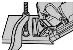
Installing and Removing the Battery Pack (Fig. 1)
WARNING: KEEP HANDS AND BODY AWAY FROM BLADE AREA WHEN INSERTING BATTERY PACK.
NOTE: Make sure your battery pack is fully charged.
To install the battery pack into the tool handle, align the base of the pack with the notch inside the tool's handle and slide the battery pack firmly into the handle until you hear the lock snap into place as shown. To remove the battery pack from the tool, press the release buttons and firmly pull the battery pack out of the tool handle. Insert it into the charger as described in the charger section of this manual.
Important!
This product is not user servicable. There are no user servicable parts

inside the charger. Servicing at an authorized service center is required to avoid damage to static sensitive internal components.
READ ALL OF THE INSTRUCTIONS IN THE BATTERY CHARGER SECTION OF THIS MANUAL BEFORE ATTEMPTING TO CHARGE THE BATTERY PACK FOR YOUR TOOL.
Always use correct battery pack (pack supplied with tool or replacement pack exactly like it.) Never install any other battery pack. It will ruin your tool and may create a hazardous condition.
Introduction
Examine Figure 2 and your plate joiner for a few minutes to become familiar with the various features and the names used to describe them. The following sections will discuss the various controls and their locations.
Overview
You have purchased a precision woodworking tool. The function of the plate joiner is to enable you to make extremely strong and accurate joints in wood and wood by products.
The tool works by a plunging action to precisely cut crescent shaped slots for the placement of flat wooden dowels or "biscuits" like those shown in Figure 3.
The various adjustments on the patented base/fence assembly will enable you to make virtually any biscuit joint imaginable. The tool may be further enhanced by some simple jigs and fixtures that can be easily
made. Some of the more common biscuit joinery applications are shown in Figure 4 and are discussed in detail in the applications section of this manual.
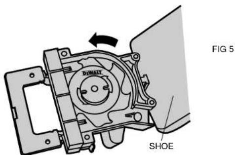
Blade Replacement (Fig. 5)
In time your saw blade will wear out and need replacement. To remove the blade, follow the steps below.
- Turn off the plate joiner and remove the battery pack.
- Remove the 4 torx head screws from the bottom of the shoe, using the T20 torx screwdriver provided.
- Rotate the shoe out of the way.
- Use the spanner wrench provided to loosen (counterclockwise) the blade nut. Depress the spindle lock pin on the top of the gear case to hold the spindle while you unscrew the nut.
- Remove the blade and have it sharpened or replace it with a new one.
- Reinstall the blade by reversing the steps above. Be sure blade teeth point counterclockwise as shown in Figure 5.
IMPORTANT: Always check the fine depth adjustment when sharpening or replacing the blade. Adjust if necessary. (See "Controls" section).
The Controls
The heart of your plate joiner is the base/fence assembly. All of the controls that let you make a variety of precision cuts are located on this assembly. Take a few minutes to become familiar with the various controls.
ALWAYS REMOVE THE BATTERY PACK FROM THE PLATE JOINER BEFORE MAKING ANY ADJUSTMENTS.
1. ADJUSTABLE FENCE
The adjustable fence provides a sturdy, precise reference surface to determine the point at which the slots for the biscuits will be cut. Its adjustable height feature allows you to position biscuit slots as close
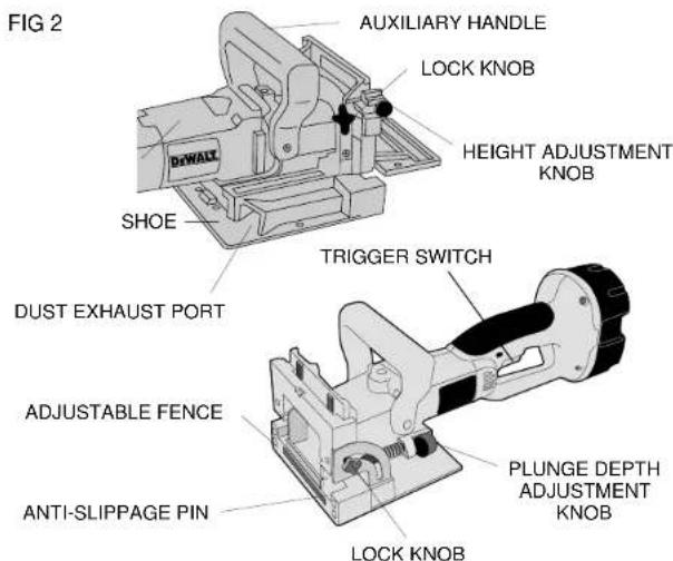
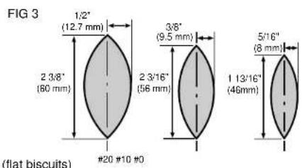
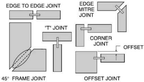
FIG4
as 3 / 16^ (4.76mm) and as distant as 1 - 3 / 8'' (35mm) measured from the workpiece surface to the centerline of the blade (see Figure 6). The adjustable angle feature allows a full range of settings from 0^ to 90 as well as a reverse 45^ bevel which allows outside registration on miter joints. (See Applications section under Miter Joints, Figure 27.) The height adjustment is accomplished by first loosening the lock knob on the right side of the fence and then rotating the knurled adjustment knob until the desired height is reached (see Figure 6). Tightening the lock knob will then automatically align the fence parallel to the blade and lock it in position. The vertical scale and pointer located directly under the lock knob can be used to assist in setting this height. The scale readings indicate distance from the blade centerline to the fence surface when the fence is set at 90^ (see Figure 7). The fence angle can be set simply by loosening the lock knob on the left side of the tool, aligning the protractor scale with the pointer and tightening the lock knob.
2. PLUNGE DEPTH ADJUSTMENT
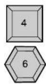
The depth of cut can be set to match the dimensions of the particular size biscuit you will be using. The numbers on the depth adjustment knob (0,10,20,M) coincide with the three sizes of biscuits shown in Figure 3. The letter M stands for the maximum depth capacity of the tool which is 20mm (25 / 32^ ) . This depth is obtainable only with a new blade and by backing out the fine adjustment screw (see next section).
NOTE: The M setting has been provided for future use and will not be necessary for most biscuiting operations. To select a depth, align the appropriate number with the red mark scribed in the tool's housing, as shown in Figure 7. Rotate the depth adjustment knob to the desired position and it will "click" into place.
3. FINE DEPTH ADJUSTMENT
You may encounter situations where you want to leave a little looseness in your joint so that you can move it slightly before the glue sets up. For these instances a fine depth adjustment has been

provided. To adjust, you must first raise the adjustable fence to its uppermost position. Then insert the T20 torx wrench provided into the opening as shown in Figure 9. Turn the depth adjustment screw clockwise for less depth and counterclockwise for increased depth. Each full turn causes a change in depth of 1mm (0.04^ ) . Always check the depth adjustment by first making test cuts in scrap wood.
4.ANTI-SLIPPAGE PINS
Plate Joiners tend to slide to the right with respect to the workpiece when making a cut. This tendency is increased with a dull blade or when plunging very rapidly. Anti-slippage pins have been provided to reduce this tendency and are located on the front registration surface on either side of the blade opening slot. When making some joints, you may wish to retract the anti-slippage pins so as not to scratch your workpiece in a visible area. For this purpose, simply rotate the anti-slippage pins approximately 1/6 of a turn and they will retract back behind the front registration surface. A flat blade screwdriver can be used to rotate the pins as shown in Figure 10.
5. BOTTOM REGISTRATION SURFACE
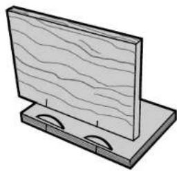
For certain applications, you will want to use the bottom surface of the plate joiner for alignment. When using the bottom registration surface, the adjustable fence should be set to 0^ and the height setting is unimportant. This surface is used primarily when making T' joints (see applications section). The distance between the centerline of the blade and the bottom registration surface is fixed at 3/8'' (9.5mm) which allows centering on 3/4'' (19mm) thick stock. The 3 red marks on the bottom registration surface indicate the centerline (or the deepest point) of the biscuit cut and the approximate width of a #20 biscuit so that you'll know where the edge of the blade is and can prevent breakthrough. To avoid breaking through the workpiece, align the shoe so that neither outside mark extends beyond the end of the workpiece. If either side does, there is a good chance that the blade will break through the surface and ruin your work.
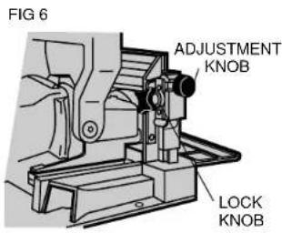
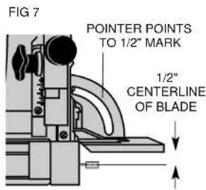
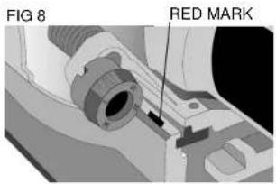
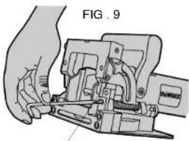
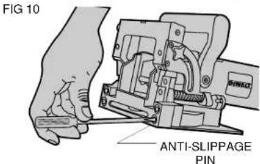
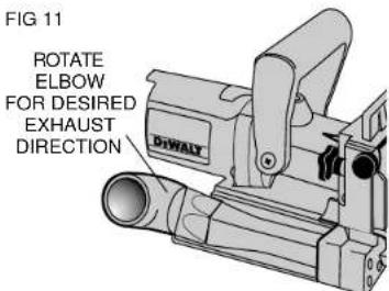

FIG 12
VACUUM HOSE ADAPTOR

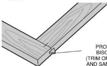
FIG 14
PROTRUDING
BISCUIT END
(TRIM OFF WITH SAW AND SAND SMOOTH)
6. DUST EXTRACTION
There are three options provided for collecting dust from your plate joiner as described below.
A. Dust Exhaust Flow Elbow (See Figure 11)
This attachment inserts into the dust exhaust port on the right side at the rear of the base assembly and clicks into place. To remove, pull out firmly. The directional elbow rotates easily to aim the dust in the most convenient direction suitable for the particular application.
B. Vacuum Hose Adaptor (See Figure 12)
This attachment, when inserted as described above, allows the use of several common sizes of vacuum hose to be attached for direct vacuum pick-up of the dust.
C. Dust Bag (See Figure 13)
The dust bag provided fits snugly over the vacuum hose adaptor as shown. To empty the bag, open the zipper underneath and dump dust out.
NOTE: When the bag becomes full, the dust will back-up into the adaptor and the exhaust port on the right rear of the tool. To clean out, turn off the tool, remove the battery pack and remove packed dust. The bag will hold the dust generated from approximately 70 to 100 #20 biscuit cuts before filling up.
General Operation
Plate joiners are primarily used for making cabinetry and furniture, joining millwork or other similar applications where a strong, accurate joint is required in wood or wood by-products. There are literally hundreds of variations of joints that can be made with your Plate Joiner. We will limit our discussion to six basic joints that can be used to build on and adapt to your own applications. The following are some basic set-up steps that will apply to all biscuit joints.
1. BISCUIT SIZE SELECTION
As mentioned earlier, the three biscuit sizes are #0, #10 and #20. It is a good rule of thumb to use the largest biscuit size that will

physically fit in the application. Unless you are joining narrow face or picture frames or using 1/2 or thinner stock, you will find the #20 biscuit size to suit most applications. After selecting the biscuit size, set the depth adjustment knob to the corresponding size (see Controls section). Also, be sure the fine depth adjustment is correctly set by first testing the fit in a scrap piece. This is extremely important to determine before glue-up.
2. BISCUIT LOCATION AND LAYOUT
Generally, biscuits may be spaced and located at your discretion. For edge joints, a good rule of thumb is to space biscuits every 6-10 inches on center. It is further recommended that biscuits be placed so that the centerline of the end biscuits is 2-3 inches from the end of the workpiece. When joining face frames or picture frames where the workpiece is narrow, choose the smaller biscuit sizes to keep from "breaking out" on the end of the joint. Breaking out should be avoided if possible, but if not assemble the joint and trim off the exposed biscuit tip after the glue sets (see Figure 14). When working with material up to 1^ thick, we advise to use a single biscuit located in the approximate center of the material thickness. If thicker stock is to be joined, use 2 biscuits across the thickness for greater strength (see Figure 15). Biscuit locations should be marked by first positioning the mating pieces exactly as they are to be assembled. Next, make a mark at 90^ to the joint interface across both pieces at the desired biscuit locations (see Figure 16). See Application section for more specific information on joint layout. The marks you make will then be aligned with one of the center registration marks on the tool, again, depending upon the specific application.
3. MAKING THE CUT
Prior to making any cut, be sure that all fence adjustments are set and lock knobs are tight. Also, be sure you have selected the proper depth setting. Clamp your workpiece firmly. Grasp the grip and auxiliary handle and position the fence firmly and squarely against the workpiece. Align the plate joiner's center registration mark with
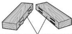
FIG 15
1" OR GREATER STOCK THICKNESS
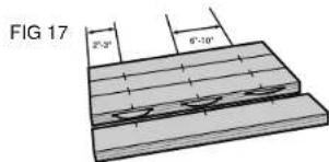
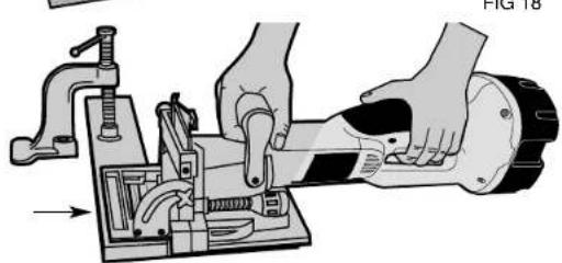
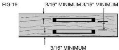
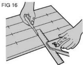
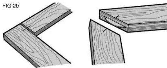
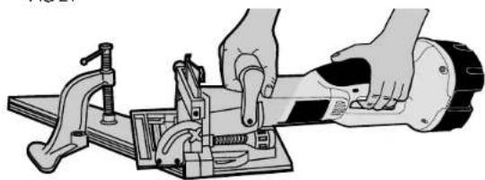
FIG 21
FIG 22
your layout mark. Turn on the tool and let the blade come up to full speed (approximately 1 second). Plunge the blade until it bottoms against the stop. Continuing to hold the tool squarely and firmly, allow the return spring to retract the blade from the work and then release the switch to shut the tool off. It will take some practice to obtain a "feel" for the tool to produce accurate joints, so practicing in scrap wood first is advisable.
4. JOINT ASSEMBLY
After your joints are cut, you may wish to trial fit everything together before gluing. When you are satisfied with your joints, evenly spread a small amount of any good quality woodworking glue in each slot and on the biscuit(s) as well as on the mating flat surfaces of your joint. Place biscuits in the slots, assemble the joint and clamp until dry. For a biscuit joint to be most effective, it is important that the biscuits themselves be in contact with the glue. This is because the biscuits absorb the moisture in the glue and expand to form a tight joint.
Applications
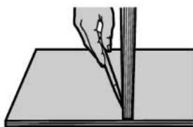
1. EDGE TO EDGE JOINTS (SEE FIGURE 17)
This is the simplest to make and most common joint for the plate joiner. Follow the steps below to produce this joint.
A. Prepare the workpieces and lay them on a work surface exactly as they are to be assembled.
B. Spacing biscuits 2-3" in from the ends and 6-10" apart, layout the biscuit centers.
C. Set up the plate joiner by first selecting the proper depth setting. Set the fence to 90^ . Set the height adjustment to position the biscuit in the approximate center of the work piece thickness.
D. Clamp the workpiece and position the tool so that the center indicator mark lines up with the first layout mark (see Figure 18). Turn on the tool and make the plunge cut. Retract the tool and release the trigger to turn the tool off. Repeat for each layout mark.
E. Glue, assemble and clamp the joint.
F. For stock thicker than 1" you may wish to use double biscuits at each location. Set the height adjustment to allow at least 3 / 16'' of stock between the biscuit and the edge of the work surface. Make all cuts at this fence setting before readjusting the fence for the lower cuts. Again, there should be at least 3 / 16'' of stock between the biscuit and the outside surface and between the biscuits themselves (see Figure 19).
2. FRAME JOINTS (SEE FIGURE 20)
Frame joints are an ideal application for biscuit joinery. With the plate joiner you can create a very strong, precise joint that is much faster to make than a dowel or mortise and tenon joint. Figure 20 shows two types of frame joints. Follow the steps outlined below.
A. Arrange the workpieces on a flat work surface exactly as they are to be assembled.
B. Select the proper biscuit size based on the length of the joint. (If the frame pieces are too narrow for a #0 biscuit, you will have to allow the biscuit tip to protrude slightly and then trim it off after the joint is dry (see Figure 14).
C. Lay out the biscuit locations.
D. Set up the tool by selecting the depth that corresponds to the chosen biscuit size. Lock the fence at 90^ and adjust the fence height to center the biscuit on the workpiece thickness.
E. Clamp the workpiece and position the Plate Joiner to make the first cut (see Figure 21).
F. Turn on the tool and make the plunge cut.
G. Repeat for each layout mark.
H. Glue, assemble and clamp the frame.
3. CORNER JOINTS (SEE FIGURE 22)
Corner joints are another common and excellent application for biscuit joinery. Follow the procedure below.
A. Arrange the workpieces exactly as they are to be joined.
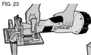
FIG.24
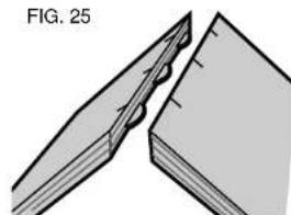
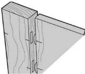
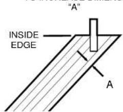
FIG.26
POSITION BISCUIT CLOSER TO INSIDE EDGE TO INCREASE DIMENSION
FIG. 27
391742/DW931,932 1/22/01 9:10 AM Fagc 13
| OF SIDES | JOINT ANGLE | FENCE ANGLE SETTING | |
| OUTSIDE REGISTRATION | MIDDLE REGISTRATION | ||
| 4 | 90° | 90° | 45° |
| 5 | 108° | 81° | 54° |
| 6 | 120° | 75° | 60° |
| 8 | 135° | 67.5° | 67.5° |
FIG. 30

B. Select the biscuit size and layout the biscuit locations.
C. Set up the tool by selecting the proper depth setting, adjusting the fence to center on the workpiece thickness and setting the angle to 90^ .
D. For this joint, you will make cuts into the edge of one workpiece and the face of another. The edge cut is performed the same as for edge to edge joints. The face cut is made by clamping the workpiece and aligning the tool as shown in Figure 23. Turn the tool on, make the plunge cut and repeat for each layout mark.
E. Glue, assemble and clamp the joint.
4. OFFSET JOINTS (SEE FIGURE 24)
You may wish to have a deliberate offset between two workpieces. This is easily accomplished with your plate joiner by performing the following steps.
A. Arrange the workpieces as they are to be assembled and layout the biscuit locations.
B. Set up the tool by selecting the proper biscuit size and adjusting the fence angle to 90^ . Select the workpiece that will be set back and adjust the fence height to center the cut within the thickness of that piece.
C. Clamp the workpiece, align the tool and make the plunge cut
D. Next, adjust the fence up by an amount equal to the desired offset. Use the scale and pointer located on the right side of the tool under the fence lock knob.
E. Clamp the second workpiece, align the tool and make the plunge cut.
F. Glue, assemble and clamp the joint.
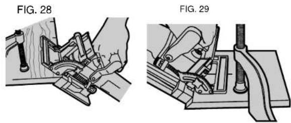
5. EDGE MITER JOINTS (SEE FIGURE 25-28)
Edge miters are most commonly used in box structures or for making multisided pedestals where you would like to hide the end grain. Once again, biscuit joinery is an outstanding method to use both for added strength as well as ease of assembly. Follow the steps below to assemble a 90^ joint.
391742/DW931,932 1/22/01 9:10 AM Page 14
English
A. Position the workpieces as they are to be assembled and layout biscuit locations on the outside of the joint.
B. Set up tool by first setting fence angle to 90^ . Make the fence adjustment such that the biscuit is located toward the inside of the joint where the material is thicker, then select the biscuit size so that the blade does not protrude through the outside wall when the cut is made (see Figure 26).
C. Clamp the workpiece and align the tool as shown in Figure 27. NOTE: Reverse 45'bevel allows outside registration on miter joints. The tool is trgistered against the outside surface. (Fig. 28)
D. Turn on the tool and make the plunge cut.
E. Glue, assemble and clamp the joint.
F. For joints other than 90^ see outside registration column Figure 30 for proper fence angle setting.
The above method will produce a joint where the outside surfaces of the joint are aligned. If you wish to produce a joint where the inside surfaces are aligned, use the following procedures for a 90^ joint.
A. Position workpieces as they are to be assembled.
B. Layout biscuit locations on the inside of the angle.
C. Set up tool by setting fence angle to 45^ . Set vertical fence adjustment so that the biscuit is located toward the inside of the joint where material is thicker. Select biscuit size so that the blade does not protrude through the outside face of the material.
D. Clamp the workpiece and align the tool as shown in Figure 29.
E. Make the plunge cut and repeat for all biscuit locations.
F. Glue, assemble and clamp the joint.
G. For joints other than 90^ see inside registration column in Figure 30 for proper fence angle setting.
6. T-JOINTS (FIGURE 31)
Biscuit joining is a viable alternative to dodoing when making a T-
joint. T-joints are most commonly used when attaching shelves to the sides of a bookcase. The method described below will work if your shelf material is at least 5/8'' thick.
A. Place the workpieces on a work surface exactly as you will be assembling them in the form of an upside down "T." Mark lightly along the joint where the top of the shelf is to end up (see Figure 31). Mark biscuit locations at the joint interface on the shelf piece only.
B. Lay the shelf down on the mating workpiece. Clamp the two workpieces together and to the work surface in this position (see Figure 32).
C. Set up the tool by selecting the proper biscuit size and setting the adjustable fence angle at 0^ .
D. Using the bottom registration surface (shoe), align the tool with the biscuit location marks and make a vertical and a horizontal plunge cut for each biscuit location as shown in Figure 33.
E. Glue, assemble and clamp the joint.
Accessories
Recommended accessories for use with your tool are available at extra cost from your local dealer or authorized service center. If you need assistance in locating any accessory for your tool, please contact your local dealer or authorized service center.
CAUTION: The use of any other accessory not recommended for use with this tool could be hazardous.
Motor Brushes
DeWALT uses an advanced brush system which automatically stops the tool when the brushes wear out. This prevents serious damage to the motor.
Important
To assure product SAFETY and RELIABILITY, repairs, maintenance and adjustment (including brush inspection and replacement) should be performed by authorized service centers or other qualified service organizations, always using identical replacement parts.
Full Warranty
DeWalt heavy duty industrial tools are warranted for one year from date of purchase. We will repair, without charge, any defects due to faulty materials or workmanship. For warranty repair information, call 1-800-4-DEWALT. This warranty does not apply to accessories or damage caused where repairs have been made or attempted by others. This warranty gives you specific legal rights and you may have other rights which vary in certain states or provics.
In addition to the warranty, DeWALT tools are covered by our:
30 DAY NO RISK SATISFACTION GUARANTEE
If you are not completely satisfied with the performance of your DeWALT heavy duty industrial tool, simply return it to the participating seller within 30 days for a full refund. Please return the complete unit, transportation prepaid. Proof of purchase may be required.
SI VOUS AVEZ DES QUESTIONS OU VOULEZ NOUS FAIRE PART DE VOS COMMENTARES CONCERNANT CET OUTIL OU TOUT AUTRE UTIL DeWALT, COMPOSEZ SANS FRAIS LE : 1 800 433-9258.
Mode recharging (Tune-UpMc)
REEMPLACEMENT DE LA LAME
BOSQUES DE CIDROS ACCESO RADIATAS NO.42
COL. BOSQUES DE LAS LOMAS. 25130 MEXICO, D.E.
05120 MEXICO, D.F. Tel: 0387-7100
TEL:326-7100
Para增值服务ventas consulte
"HERRAMIENTAS ELECTRICAS"