USER MANUAL HC 410 G METABO
We herewith declare in our sole responsibility that this product complies with the following standards in accordance with the regulations of the undermentioned Directives EC type examination *** conducted by****
NL NEDERLANDS
Please note the following supplementary information associated with this machine:
U.K. Legislation and Codes of Practice
When used industrially within the U.K. this machine falls under the scope of
- Whoodworking Machines Regulations 1974 and
- Used and Provisions of Work Equipment Regulations 1992
We strongly advice you study and follow these regulations.
Paragraph 7.3 Connection to Power Mains
230 V motor. The motor supplied with this machine will not run on a 13 A domestic ring main. On starting the machine a high current of very short duration is drawn, which will blow your 13A fuse. This machine can only be connected to a 16A separate radial circuit using BS 4343 (CEE 17) socket and plug. Ensure the installation is protected by a suitably sized fuse or miniature circuit breaker.
This work should only be undertaken by a qualified electrician!
Wiring Instructions
Warning: This appliance must be earthed!
If the plug, fitted to the power cable supplied with the machine, has to be changed or replaced, connect the mains lead conductors in accordance with the following colour code.
Three-phase motors (220/380/400/415 volts):
Machines with a 3-phase motor are connected to power mains using a 5-pin industrial appliance-inlet/connector according to VDE 0623/BS 4343/IEC 309.
4-wire mains lead Yellow/green - Earth
Brown - Phase (L1)
Black - Phase (L2)
Black - Phase (L3)
5-wire mains lead Yellow/green - Earth
Brown - Phase (L1)
Black - Phase (L2)
Black - Phase (L3)
Blue - Neutral
IF IN DOUBT - CONSULT A QUALIFIED ELECTRICIAN!
Contents
1 Specifications
2 User Responsibility
3 Standard Delivery
4 Optional Accessories
5 Scope of Application
6 Transportation
7 Installation/Initial Operation
8 Safety
9 Workpiece Dimensions
10 Dangerous Operations
11 Push Blocks
12 Controls
13 Operation
14 Daily Safety Checks
15 Replacing/Setting the Planer Blades
16 Care and Maintenance
1 Specifications HC 410 D
Stock-no.: 0113041013
Planing bed overall length: 1700mm
Max. planing width: 410 mm
Depth of cut, planing: 0-5 mm
Fence tilt: 90^ - 45^
Length thicknessing bed: 670 mm
Thicknesser capacity - width: 405 mm
Thicknesser capacity - height: 230 mm
Max. depth of cut, thicknessing: 5 mm
Thicknesser feed rate: 7m / min
Cutterblock speed:
No. of planer blades:
Motor capacity P;
Voltage, motor:
Voltage, control circuit:
Input capacity:
Mains fuse:
Weight:
Floor space required, approx.:
Working height, planing:
5500 rpm
33
5.5 kW
3~400 VAC 50 Hz
230 VAC
7.0 kVA
3x16 A time-lag
275 kg
1740 × 800 ~mm
900 mm
Workplace related noise emission values L_p according to DIN 45635, part 1651, idling:
Required vacuum at dust collection port: 900 Pa.
Planing: 84,0 dB(A)
Thickening:
87,3 dB(A)
2 User Responsibility
This machine will perform in conformity with the description contained in the instructions provided. This machine must be checked periodically. Defective equipment (including power cable) should not be used. Parts that are broken, missing, plainly worn, distorted or contaminated, should be replaced immediately. Should such repair or replacement become necessary, it is recommended that such repairs are carried out by qualified persons approved by metabo or its authorized representatives.
This machine or any of its parts should not be altered or changed from standard specifications. The user of this machine shall have the sole responsibility for any malfunction which results from improper use or unauthorized modification from standard specifications, faulty maintenance, damage or improper repair by anyone other than qualified persons approved by metabo or its authorized representatives.
metabo reserves the right to change specifications and design without prior notice and without incurring obligation of any kind. Equipment referred to as available or optional may be at extra cost.
3 Standard Delivery
4 Optional Accessories
Resharpenable planer blades, TCT, 410x25 mm Stock-no. 091 105 0390
Drilling and Morticing Attachment Stock-no. 091 101 4211
Digital Readout for Thicknesser Stock-no. 091 101 3983
Wheel Set HC 410 Stock-no. 091 101 4203
Planer Blade Setting Tool Stock-no. 091 101 6397
5 Scope of Application
The surface planing and thicknessing machines models HC 410 are designed for planing/thicknessing wood or derived timber products* of square or rectangular crosssection. Round workpieces or workpieces which do not fully rest on the planing/thicknessing bed, or can not be positively held by the thicknesser's recoil lock (e.g. battens with a triangular crosssection) can not be worked on these machines.
*Derived timber products are materials containing a minimum of 90% wood particles.
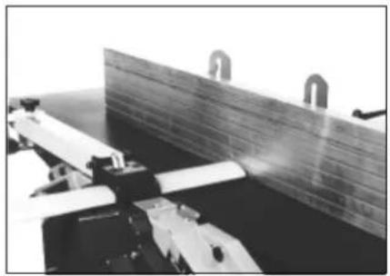
6 Transportation
To remove the machine from the pallets and for transportation 4 lifting eyes are provided. Place a tube or batten through the eyes to maneuver the machine. After installation of the machine the lifting eyes should be removed.
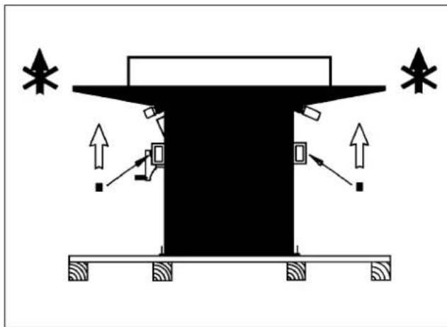
Do not lift machine on the planing bedes.
7 Installation/Initial Operation
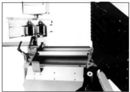
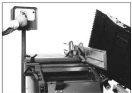
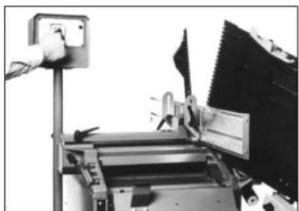
7.1 Final Assembly
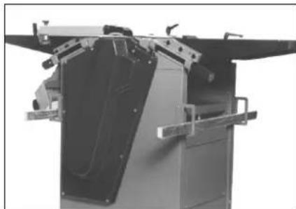
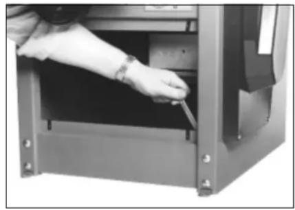
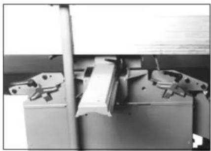
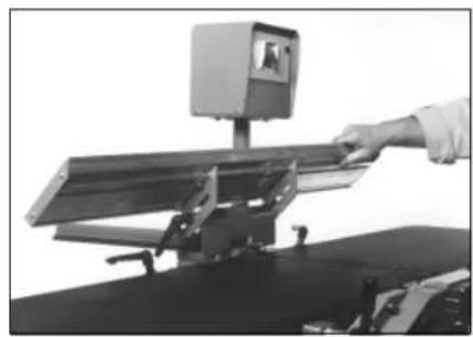
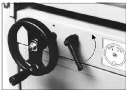
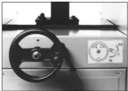
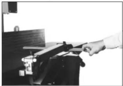
For shipping the fence is not installed and the switch terminal is mounted in a horizontal position.
Loosen the screws of the stay brackets, put switch terminal in the vertical position and tighten screws again.
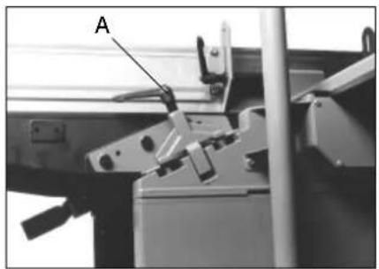
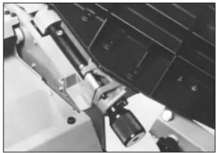
Loosen ratchet lever (a) and slide fence carrier into bracket.
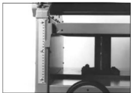
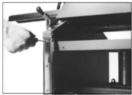
7.2 Installation
The machine must be installed on a firm and level floor. Adjust feet until planing beds are level. All four feet must evenly rest on the floor to prevent rocking.
7.3 Connection to Power Mains
- Check if voltage of power mains matches with voltage stated on machine's type plate (400 V 50 Hz ±5%).
- This machine must be operated on a residual current device (RCD) of 30mA capacity, having a fault current breaker.
- The outlet this machine is connected to must be earthed and each phase protected by a 16 A time-lag fuse or circuit breaker. A minimum conductor crosssection of 2.5mm^2 is required.
- This machine must be safety earthed. The yellow/green lead is the earth conductor. If a plug matching your local standard outlet is fitted to the power cable, do not connect the earth lead to one of the current conducting leads.
- Do not operate this machine with a damaged power cable. Risk of electrical shock.
- Worn or defective cables must be replaced immediately. Have replaced by a qualified electrician only.
7.4 Direction of Rotation
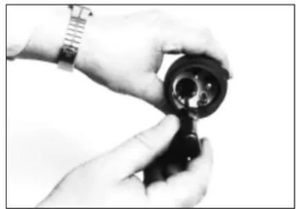
Important! The direction of rotation of the cutterblock must be against the feed direction. It is factory set on single-phase machines. On machines equipped with a three-phase motor, start machine briefly to check direction of rotation. To change, turn phase inverter pins in plug by 180^ with screwdriver.
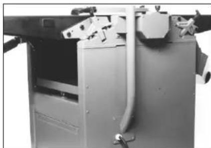
7.5 Dust Collection
If this machine is operated indoors for more than 30 minutes a day it must be connected to a dust collector (the dust of oak and beech is classified as cancer causing). The dust collector this machine is connected to must provide for a minimum air flow rate of 16 mtr/sec.
The dust collection port of the dust chute has a nominal diameter of 100mm
7.6 Automatic Dust Collector Starting
The electrical connection of this machine must ensure that a dust collector connected to it automatically starts when the machine is switched on, and provide for 20 sec post-running of the dust collector after the machine is switched off.
8 Safety


- Adhere to the instructions, the safety rules in particular.
- Disconnect from power (pull plug form outlet) before servicing.
- Check guards daily as per para. 14 of this manual.
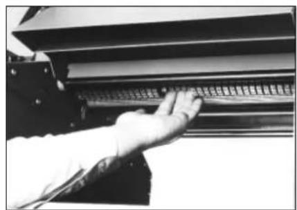
- Never reach into feed openings while machine is running. Observe warning label with crossed-out hand on machine, indicating the danger (see also above).
- Follow instructions for fence and guard setting (para. 12.4 and 12.6).
- Do not use planer blades of less than 22mm width.
- Dust collection as per para. 7.5 of this manual must be provided for.
- Do not work stock larger than the max. workpiece dimensions as per para. 9.
- Never operate machine without cutterblock guard in place.
- Replace damaged parts and safety guards at once with genuine metabo parts.
- Person under the age of 16 are not permitted to operate this machine.
- In case of disturbances always let the cutterblock come to a complete standstill before checking the machine.
-
Always have guard and fence set for the job on hand.
-
Always wear snug fitting clothes and take off rings, bracelets and watches before operating this machine.
- While this machine is in operation the cutterblock must be completely covered, by fence, cutterblock guard, and workpiece.
- Wear hearing protection for all jointing and planing operations (warning symbol shown above). The sound pressure level can reach up to 87 dB(A).
- Check stock before working it for cracks, intergrown knots, warps and inclusion of foreign material.
- Do not exceed maximum permissible torque when tightening lock bar screws (see para. 15).
- When operated with wheel set installed support machine with all four levelling screws to keep it from tipping.
9. Workpiece Dimensions
9.1 HC 410
Planing/Jointing
The max. permissible workpiece size is 1700 × 410 ~mm when using the standard machine tables. If workpieces of greater length are to be worked additional support is required, e.g. by using roller stands. The smallest size for manual feeding by hand must not be less than 300 × 40 × 20 ~mm . Smaller workpieces must be fed with a suitable push block.
Thickening
The maximum workpiece size is 1700 × 405 × 230 mm . For longer work additional support (roller stands) is required. Minimum size is 250 × 15 × 5 mm .
9.2 Stock Pre-Checking
Every workpiece must be checked for possible flaws, to see if it is suitable for planing/thicknessing (warping, knots, cracks, inclusions of foreign material), before it is worked.
Caution! Do not work stock with loose knots or knots which may fall out easily.
- The knots coming off may be thrown about, with a risk of personal injury and damage to the machine.
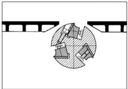
10 Dangerous Operations
- With this planer/thicknesser no set-in work must be carried out. Set-in work is a planing operation where the planing starts or stops short of one end of the workpiece.
- Do not attempt to plane heavily warped stock, which does not rest with its full length on the planing tables.
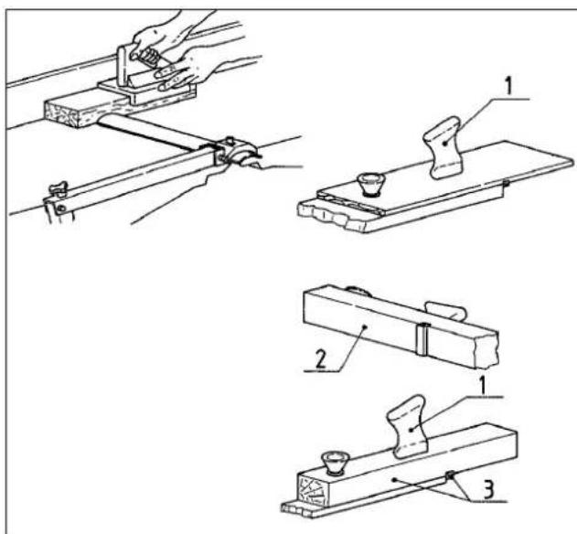
11 Push Blocks and Feeding Fixtures
1) Handles dowelled and glued to prevent metal making contact with the planer blades.
2) Underside of push block faced with sandpaper or soft rubber, for better contact and guiding of the workpiece.
3) Use narrow, two-handed push block for short, narrow and thin stock. Glue a piece of hardwood across the push block serving as stop.
12 Controls
12.1 Switch Terminal/Electrical Equipment
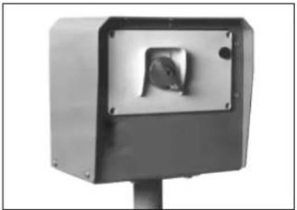
The raised switch panel can be turned to point towards the operator position for easy access. Turn rotary switch clockwise to start machine, turn counter-clockwise to switch the machine off. To prevent unauthorized use the switch can be blocked with a padlock.
Three limit switches, located behind the thicknesser drive gear cover, prevent the starting of the machine if it is not properly set for the planing or thicknessing mode. The limit switches will also switch the machine off if -the planing beds are swung up -the chip ejection hood is swung from the cutterblock when thick-. nessing
12.2 Switch/Overload Protection
The switch is equipped with a no-volt release solenoid (magnetic switch), to prevent start-up after a power failure. If the machine is not connected to the power mains the switch does not engage. In the event of a power failure the machine has to be restarted. In case of an overload of the motor the build-in motor protection relay trips and cuts the power to the motor. If the motor is shut off repeatedly by the overload relay, check machine (motor brake action, blade sharpness, low voltage etc.) A cooling down period of 10 min. is recommended before switching ON again.
12.3 Motor Brake
The motor supplied with this machine is equipped with an electro-mechanical motor brake, designed for a long service life. Friction, however, causes the brake pad to wear. If the braking action fades (time to cutterblock standstill exceeds 10 sec.) the motorbrake has to be replaced. The max. permissible number of 10 switching actuation per hour should not be exceeded.
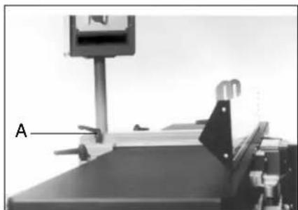
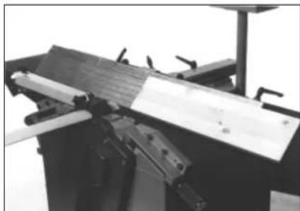
12.4 Canting Fence Adjustment
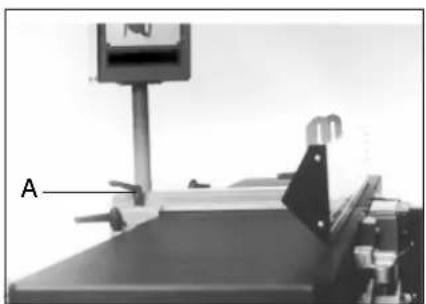
Loosening the ratchet lever (A) allows for lateral adjustment of the fence carrier.

After loosening both ratchet levers (B) the fence can be set from the 90^ position to the 45^ position.
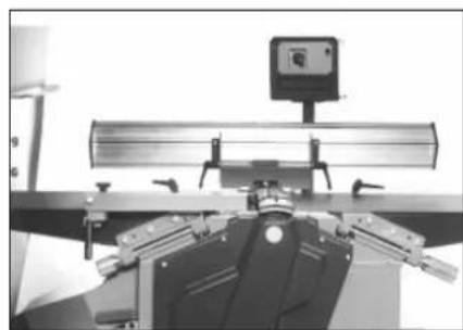
When changing from planing to thicknessing mode the fence is swung up.
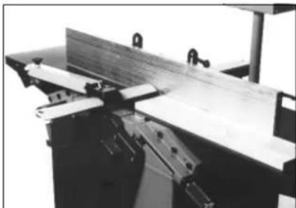
12.5 Setting of Fence
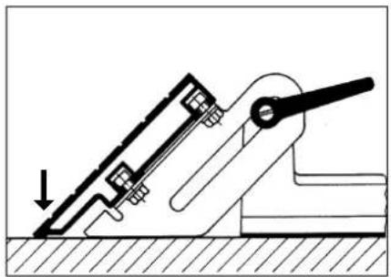
Notice: Always set fence so it rests flush on the planing tables (see arrow).
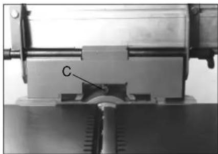
The 90^ position of the fence extrusion against the planing beds can be set by adjusting setting screw (C).
12.6 Cutter Guard Setting
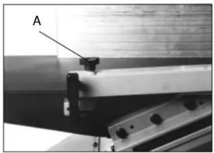
The cutter guard throat height is set by turning the starknob screw (A) clockwise or counter-clockwise.
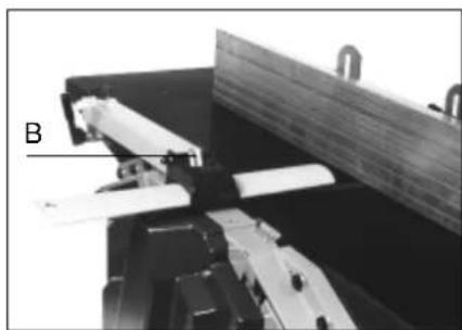
For jointing the opening between the fence and the guard extrusion can be set after loosening the lock lever (B).
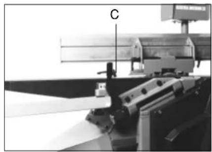
Before the planing beds can be opened, the cutter guard assembly must be swung out of the way by 180^ . Loosen lever (C), swing assembly over and retighten lever.
12.7 Setting Depth of Cut/Scale Reading
Prior to any adjustment loosen ratchet lever (A) approx. 1/2 turn.
Turning the knurled setting handle (B) raises or lowers the infeed table.
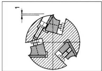
The set depth of cut is indicated by the venier scale. After required depth of cut is set retighten the ratched lever (A).
1 matching 1 = 1 mm depth of cut
2 matching 2 = 2 mm depth of cut
etc.
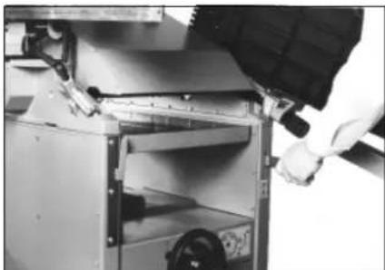
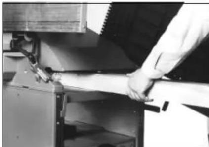
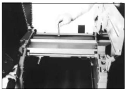
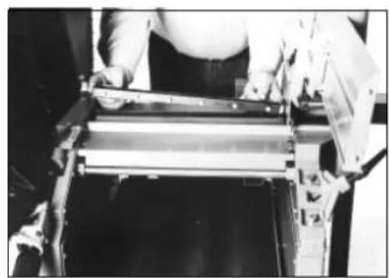
12.8 Changing to Thicknessing Mode
Swing guard assembly over. Loosen
both clamping brackets and swing clear of the table brackets.
Swing fence extrusion up and secure in position.

Swing open both infeed and outfeed table.
With planing beds in upright position check that safety latches are in position, preventing the inadvertent closing of the tables.
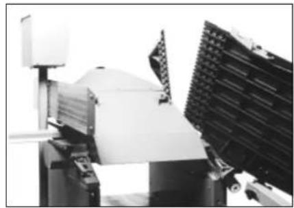
Swing chip ejection hood over the cutterblock.
Note! Swing safety latches up before closing the planing beds.
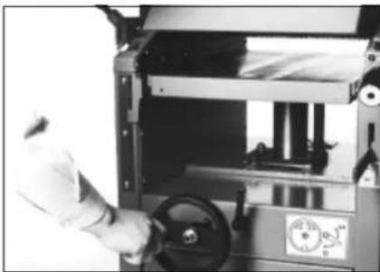
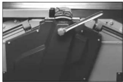
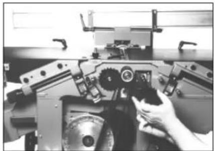
12.9 Thicknesser Bed Setting
Loosen lock before making adjustment.
The thicknesser bed rise and fall is actuated by the cranked handwheel. Turn clockwise to rise, turn counterclockwise to lower the thicknesser bed.
The set thickness is indicated on the thicknesser scale. After setting to required thickness retighten the lock.
To assist in setting to within 1/10th of a millimetre, a digital readout is available as optional accessory (Stock-No. 091 101 3983).
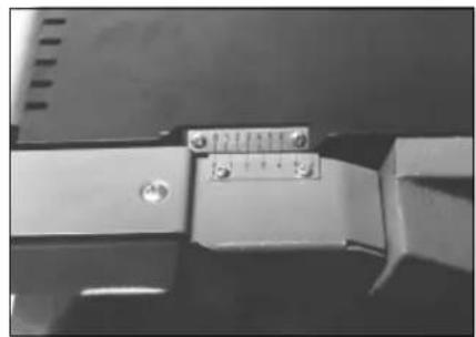
12.10 Thicknesser Scale Adjustment
Loosen the three screws holding the scale, then move it up and down in the slots as required.
12.11 Feed Gear Clutch
Push clutch lever down to disengage the feed gear clutch.

13 Operation
13.1 Ticknessing
Set up machine for thicknessing as described in para 12.8 and connect with suction hose to a dust collector.
Set thicknesser bed to desired workpiece thickness.
Start machine and engage feed gear clutch.
Place workpiece with the already planed side facing down onto the thicknesser bed and slide forward until the infeed feed roller gets hold of it.
The workpiece is now automatically fed through the thicknesser and has to be received by the operator on the outfeed side of the machine. Stock longer than 1.6/1.7 meter requires additional support.
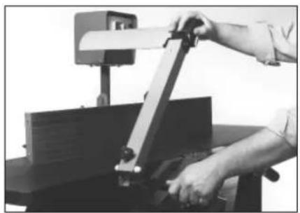
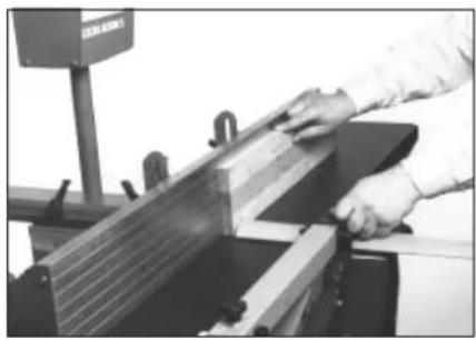
13.2 Planing/Surfacing Flat Stock
Set machine up for planing. Swing cutterblock guard assembly in position and connect machine with suction hose to a dust collector.
Set fence forward so that the fence carrier extrusion covers the cutterblock, to expose only the width of the workpiece.
Set cutterblock guard against the fence and lock in position. Max. permissible opening between fence and guard extrusion is 8mm
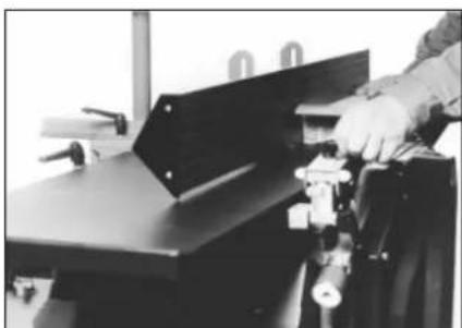
Set guard assembly to workpiece thickness by turning the starknob setting screw as required. Stock up to 60mm thickness is always passed underneath the cutterblock guard.
When feeding the hands glide over the cutterblock guard.
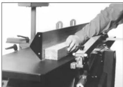
13.3 Jointing Edges
Lower cutter guard assembly to rest on the planing beds.
Set cutterblock guard to width of workpiece. A tolerance of 4mm is acceptable.
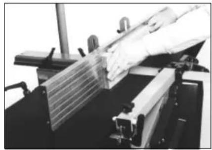
With this setting the hands must not pass over the cutterblock
The left hand always stays behind the cutterblock.
The right hand feeds the workpiece, but is repositioned before it passes the cutterblock.
14 Daily Safety Checks
Attention! Disconnect from power before servicing.
The outfeed table must be exactly in line with the cutting circle of the planer blades. If too high, the workpiece will hit the edge of the outfeed table. If set too low, the cutterblock body can touch the workpiece and throw it back at the operator (increased danger of kickback). See para. 15.4.
The cutterblock guard must be adjustable without having to exert too much force. Lubricate regularly. Replace broken or defective parts of the cutter guard assembly at once. The cutterblock guard must not slide when locked in position. Replace lock lever immediately if worn.
The anti-kickback fingers of the recoil lock must fall down by their own weight. Clean recoil lock regularly to ensure they move freely. The tips of the anti-kickback fingers must be kept pointed and sharp.
15 Replacing/Setting the Planer Blades
Attention! Disconnect from power before servicing.
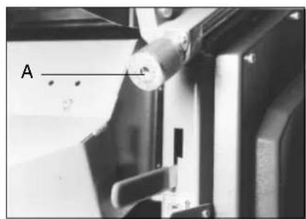
The outfeed table must be set 0.1 mm lower than the uppermost position of the blade.
To set, loosen counter screw A of the setting knob, than turn knob clock- or counter-clockwise to adjust the outfeed table position.
Note: The blades must have a minimum width of 22mm Smaller blades can not be securely locked. The cutterblock wedge locking screws must be tightened to a max. torque of 9 Nm. Applying more torque may strip the threads. Use only the spanner supplied wit tool set to tighten the locking screws.
Max. planerblade projection over the cutterblock is 1.0mm
15.1 Planer Blade Removal
For removal and installation of planer blades lift both planing beds up.
Loosen all 6 locking screws of the cutterblock wedge with a 10mm open end spanner (turn clockwise).
The blade and the cutterblock wedge can now be lifted from the cutterblock.
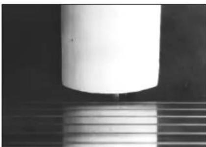
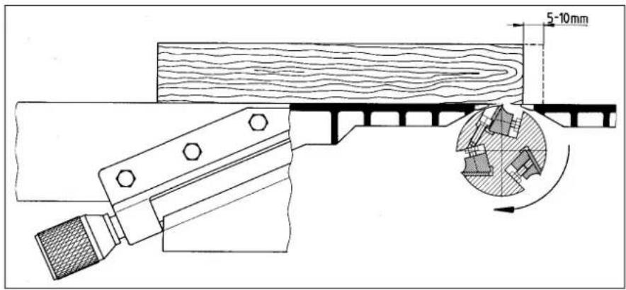
15.2 Checking Planer Blade Setting
To check the correct outfeed table setting, place a straight edge, ruler or a planed batten on the outfeed table and across the cutterblock. Slowly turn cutterblock by hand. The blade must lift the straight edge/ruler and pull it forward by 5 - 10 mm. Mark start and stop position of ruler with pencil on table. Carry out this check on the left and right side of each of the three blades. For a safe operation of this planer/ticknesser it is important that the installation and checking of the blade table setting is carried out very carefully (risk of accident and personal injury to the operator.
16 Care and Maintenance 16.1 Lubrication
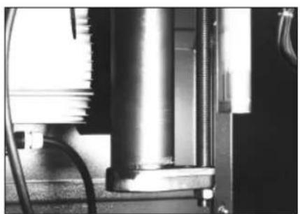
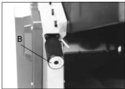
The thicknesser bed column has a lubricator nipple. Lubricate at least once a year.
Regularly apply a few drops of oil to the planing bed hinges and to all other moving parts.
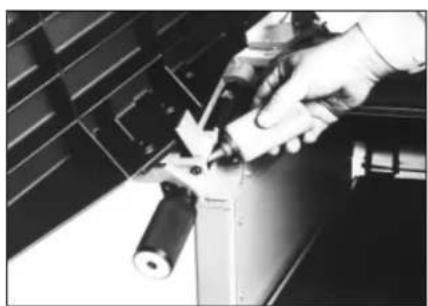
To assist in manually turning the cutterblock, remove the lid and place a 24mm socket wrench on the cutterblock nut (wrench not supplied with the tool set).
Lubricate feed roller bearings with a few drops of oil, as required, but at least once a year.
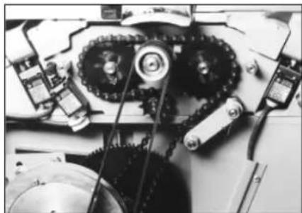
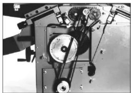
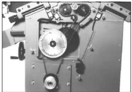
16.2 Drive Belt Tension/Replacement
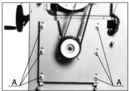
After loosening the six nuts (A) the motor mounting plate can be pushed downward to tension the main drive belt.
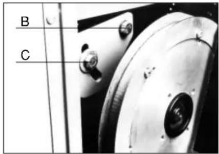
Loosen screws (B and C) to move the transmission base plate for tensioning the thicknesser drive belt.
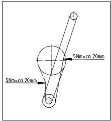
Play of main drive belt at 5 Nm tension approx.20 mm
Play of thicknesser drive belt at 5 Nm approx.20 mm.
16.3 Servicing/Replacing the Recoil Lock
Damaged or worn anti-kickback fingers must be replaced by genuine metabo anti-kickback fingers (see spare parts list for ordering information).

After removal of the two fastening screws the recoil lock assembly is removed from the machine.
New anti-kickback fingers must slide easily and move freely on the recoil lock shaft. After the recoil lock assembly is reinstalled check for its proper function.
16.4 Checking Limit Switches and Motorbrake
Note: In case of a damaged limit switch lead the machine may start during testing. This test should therefore only be carried out by qualified service personnel.
Swing the infeed table up to its upright position and cover the cutterblock by setting the fence assembly against the table.
When actuating the switch the machine must not start.
Swing the outfeed table up to its upright position and cover the cutterblock by setting the fence assembly against the table.
The braking period (time to motor standstill) must be checked in at least monthly intervals. The braking period must not be more than 10 sec. If the motor needs more then 10 sec. to come to standstill, the motorbrake or the complete motor have to be replaced.
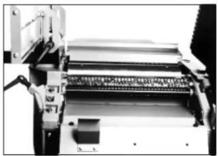
16.5 Changing the Feed Rollers
Remove the drive gear cover, lift the drive chain from the sprockets and pull the sprocket from the shaft.
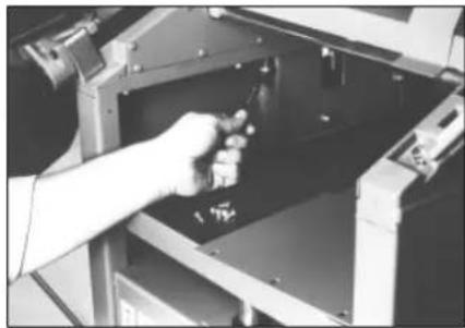
Remove the pressure spring with its fastening screws. The feedroller can then be pulled out from the side.
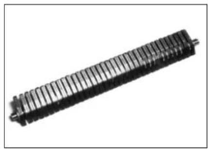
16.6 Changing the Cutterblock
Remove the drive gear cover and take the main drive belt off the pulleys.
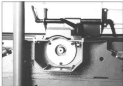
Take off the cover plate and remove the three screws holding the cutterblock bearing.
The cutterblock can now be pulled out.
Table des matieres
Please replace this page by „ More of metabo - tools “