
P 3000 G - Pump METABO - Free user manual and instructions
Find the device manual for free P 3000 G METABO in PDF.
| Product type | Clean water pump |
| Brand | Metabo |
| Model | P 3000 G |
| Category | Lift pump |
| Dimensions (L \u00d7 W \u00d7 H) | 375 \u00d7 185 \u00d7 250 mm |
| Weight empty | 14.0 kg |
| Weight with water | 14.5 kg |
| Mains voltage | 230 V ~ (50 Hz) / 110 V ~ (60 Hz) |
| Rated power | 900 W (230 V) / 950 W (110 V) |
| Rated current | 3.7 A (230 V) / 9.7 A (110 V) |
| Recommended fuse | 10 A (230 V) / 15 A (110 V) |
| Max. flow rate | 3000 l/h |
| Max. delivery head | 43 m |
| Max. discharge pressure | 4.3 bar |
| Max. suction head | 8.5 m |
| Max. feed temperature | 35 \u00b0C |
| Protection rating | IP X4 |
| Protection class | I |
| Housing material | Grey cast iron |
| Impeller material | Noryl |
| Suction connection | 1" IG |
| Pressure connection | 1" IG |
| Sound level (L_WAd) | 75 dB(A) |
Frequently Asked Questions - P 3000 G METABO
User questions about P 3000 G METABO
0 question about this device. Answer the ones you know or ask your own.
Ask a new question about this device
Download the instructions for your Pump in PDF format for free! Find your manual P 3000 G - METABO and take your electronic device back in hand. On this page are published all the documents necessary for the use of your device. P 3000 G by METABO.
USER MANUAL P 3000 G METABO
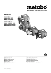
natural_image
Line drawing of an electric motor with attached power outlet and cable (no text or symbols)P 3000 G

(D) Originalbetriebsanleitung. 3
ENG Original operating instructions 8
F Instructions d'utilisation originales ..... 13
NL Origineel gebruik aanwijzing.... 19
④ Original brugsvejledning 24
ES Manual de instrucciones original ..... 29
SLO Izvirna navodila za uporabo. 35
FIN Alkuperäiskäyttöohje 40
DE EN
EG-KONFORMITÄTSERKLÄRUNGVEC-DECLARATION OF CONFORMITY
We herewith declare in our sole responsibility that this product complies with the following standards' in accordance with the regulations of the undermentioned Directives** issuing test office *** measured/guaranteed noise sound power level****
NL
Director Innovation, Research and Development
Dokumentationsbevollmächtigter/ responsible person for documentation/ Chargé de la documentation
Metabowerke GmbH
Metabo-Allee 1
D - 72622 Nürtingen
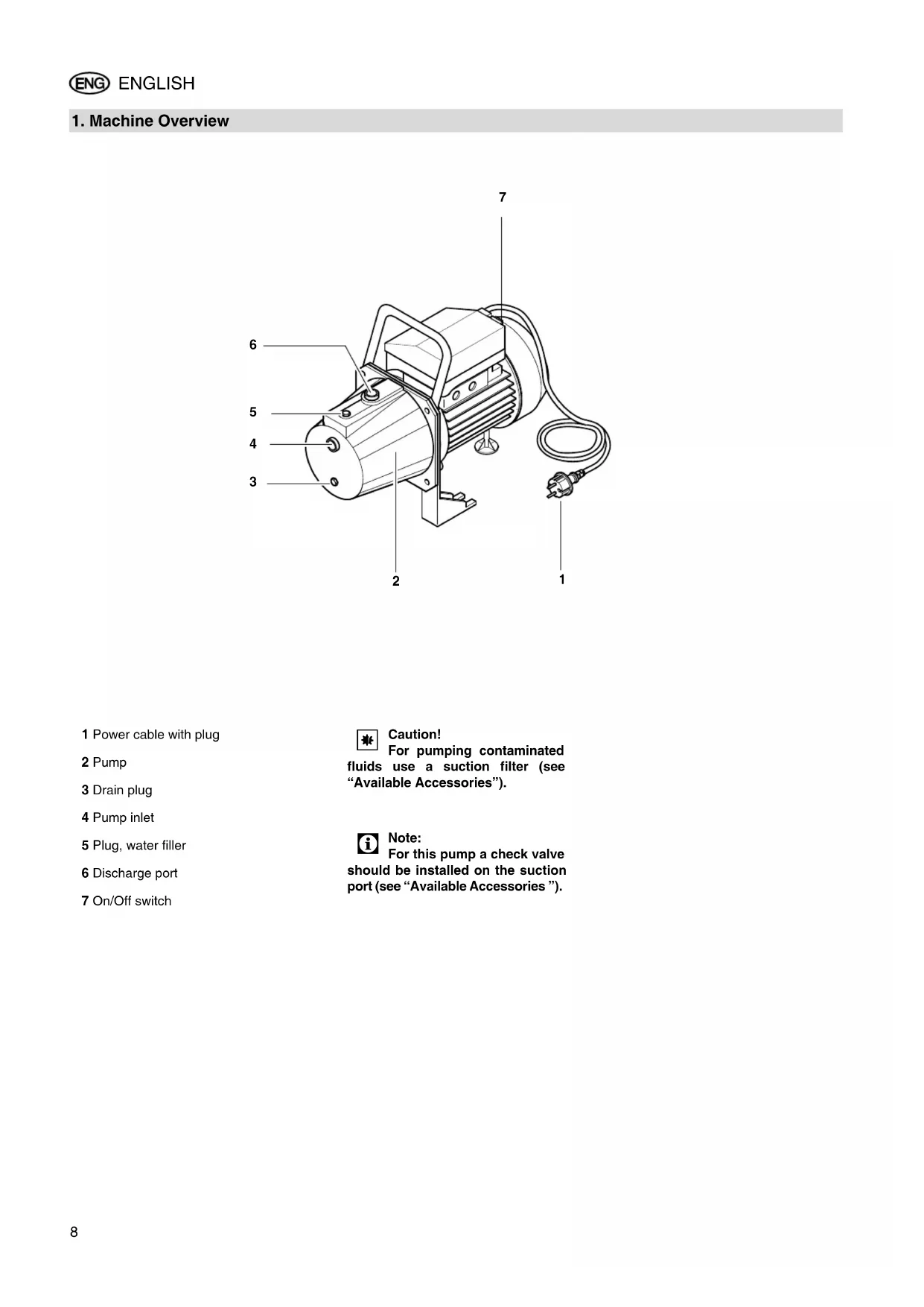
1 Power cable with plug
2 Pump
3 Drain plug
4 Pump inlet
5 Plug, water filler
6 Discharge port
7 On/Off switch

Caution!
For pumping contaminated fluids use a suction filter (see "Available Accessories").

Note:
For this pump a check valve should be installed on the suction port (see "Available Accessories").
Table of Contents
- Machine Overview ......8
- Please Read First!...... 9
- Range of Application and Pumping Media ....9
- Safety......9
4.1 Specified conditions of use .....9
4.2 General safety instructions .....9 - Prior to Operation......10
5.1 Installation....10
5.2 Suction line connection.....10
5.3 Discharge port 10
5.4 Mains connection.....10
5.5 Filling the pump and priming.....10 - Operation......11
- Care and Maintenance......11
7.1 Danger of freezing .....11
7.2 Equipment dismounting and storing ....11 - Trouble Shooting......11
8.1 Fault finding .....11 - Repairs......11
- Environmental Protection......11
- Available Accessories ......12
- Technical Specifications......12
2. Please Read First!
These instructions are written in a way that will enable you to safely use the machine in a minimum of time. Here is how to read the instructions:
- Read these instructions completely before use. Pay special attention to the safety instructions.
These instructions are intended for persons having a basic technical knowledge in the handling of machines such as the one described here. If you have no experience with this type of machine you are advised to seek the advice of an experienced individual before operating this machine. - Keep all documents supplied with the machine for future reference. Retain proof of purchase for possible warranty claims.
- If you hire out or sell this machine be sure to hand over the machine documents supplied.
- The equipment manufacturer is not liable for any damage arising from disregard of these instructions.
The information in these instructions is denoted as under:

Danger!
Warning of personal injury or environmental damage.
Risk of electric shock!
Risk of personal injury by electric shock.

Caution!
Risk of material damage

Note:
Additional information.
– Numbers in illustrations (1, 2, 3, ...)
– indicate component parts;
- are consecutively numbered;
- refer to the corresponding numbers in brackets (1), (2), (3) ... in the neighbouring text.
– Instructions to be carried out in sequence are numbered.
- Instructions which can be carried out in any sequence are preceded by a bullet.
– Listing are preceded by a M-dash.
3. Range of Application and Pumping Media
This equipment is intended for pumping clear water in domestic applications, such as
- irrigation,
- well, rain and service water pumping,
- draining of pools, garden ponds and water tanks.
The max. permissible temperature of the pumped medium is 35 °C.
4. Safety
4.1 Specified conditions of use
This equipment must not be used to supply drinking water or for pumping foodstuff.
Explosive, flammable, aggressive fluids or substances detrimental to health and salt water must not be pumped.
This equipment is not suitable for commercial or industrial use.
Alteration of the equipment or use of parts not approved by the equipment manufacturer is not permitted.
Any improper of the pump is not as specified; it may cause unforeseeable damage!
4.2 General safety instructions
Children, juveniles and persons not familiar with the instructions are not permitted to operate the pump.
When used in swimming pools and garden ponds and their range of protection, the regulations according to DIN VDE 0100-702, -738 are to be observed.
When used as domestic water supply any applicable local regulations pertaining to water supply and waste water disposal, plus DIN 1988 (where applicable) are to be observed.
The following residual risks do principally exist when operating pumps and pressure vessels and can not be fully eliminated – even by employing safety devices.

Hazard by ambient conditions!
- Do not expose to rain. Do not operate in damp or wet environment.
- Do not use the pump in hazardous locations or near inflammable liquids and gases!

Danger: Hot water!
If the shut-off pressure of the pressure switch cannot be reached due to poor pressure conditions or a defective pressure switch the water can heat up within the pump as a result of internal circulation.
Through this the pump and the connection lines can become damaged or leaky, allowing hot water to escape. Danger of scalding!
- Do not operate the pump against a closed pressure line for longer than 5 minutes.
- Unplug the pump and allow to cool. A specialist must check the system to make sure it is in perfect working order before it can be used again.

Danger! Risk of electric shock!
- Do not direct water jet directly against the equipment or other electrical parts! Risk of fatal electric shock!
- Do not touch the plug with wet hands! To unplug always pull on the plug, not the power cable.
- The earthed outlet or the plug connection to an extension cable must be located in an area safe against flooding.
- Use only extension cables of sufficient lead cross section (see "Technical Specifications"). Unroll cable reels fully.
- Do not kink, squeeze, drag or run over power supply cable and exten-
sion cords; protect from sharp edges, oil and heat.
- Place extension cable so that it can not get into the fluid to be pumped.
- Unplug:
- prior to all servicing;
- when persons are in the swimming pool or garden pond.

Danger by pump failures!
- If you notice transport damage while unpacking, notify your supplier immediately. Do not operate the machine!
- Before each use check the pump, especially the power cable and plug for possible damage. Risk of fatal electric shock!
- A damaged pump must be work-manlike repaired before it can be used again.
- Do not attempt to repair the equipment yourself! Only trained specialists are permitted to service or repair pumps or pressure vessels.

Caution!
To avoid water damage, e.g. flooded rooms, caused by pump malfunctions or defects:
• provide for suitable safety measures such as the following:
- alarm or
– collection tank with monitoring.
The manufacturer is not liable for any damage caused by:
– improper use of the pump;
– overloading of the pump through continuous operation;
- failure to operate and store the pump in a frost-free environment;
- unauthorised modification of the pump (repairs to electrical equipment may only be carried out by qualified electricians!);
– use of spare parts which have not been tested and approved by the manufacturer; or
– use of unsuitable installation materials (fittings, connection lines etc.).
Suitable installation materials:
– pressure-resistant (min. 10 bar)
- heat-resistant (min. 100°C).
5. Prior to Operation
The equipment is easily assembled and connected.
If in doubt, contact your specialist supplier or qualified electrician.
5.1 Installation
- The equipment must be placed on a plane and level surface, suitable of
bearing the weight of the equipment fully filled with water.
- Um Vibrationen zu vermeiden, sollte das Gerät auf eine elastische Unterlage gestellt werden.
- The installation location should be well vented and protected from atmospheric exposure.
- When operated at garden ponds and pools the equipment must be set up safe against flooding and protected from falling into the water. Any additional legal requirements are to be observed.
5.2 Suction line connection

Note:
Possibly further accessories may be required for connection (see "Available Accessories").

Caution!
The suction line needs to be installed in such manner that it does not exert mechanical force or distortion to the pump.

Caution!
When pumping contaminated fluids install a suction strainer to protect pump from sand and dirt.

Note:
A check valve is recommended to prevent water backflow when the pump is switched off.
- All screw fittings are to be sealed with thread sealing tape; leakages cause priming of air and reduce or prevent the priming of water.
- The suction line should be of at least 1" (25 mm) inner diameter; it must be resistant to buckling and vacuum proof.
- Keep suction line as short as practical, since with increasing length the pump capacity is reduced.
- The suction line should raise towards the pump to prevent air locks.
- A sufficient water supply must be ensured, the foot valve at the end of the suction line must be submerged in water at all times.
5.3 Discharge port

Note:
Possibly further accessories may be required for connection (see "Available Accessories").

Caution!
The discharge (or pressure)
line needs to be installed in such manner that it does not exert mechanical force or distortion to the pump.
- All screw fittings should be sealed with thread sealing tape to prevent leakage.
- All parts of the pressure line must be resistant to internal pressure.
- All parts of the pressure line must be installed in a workmanlike manner.

Danger!
Improper installation and use is not resistant to internal prescan cause the pressure line to during operation. Risk of per-injury by liquid spurting from the under high pressure!
5.4 Mains connection

Danger! Risk of electric shock!
Do not operate the equipment in wet environment and only under the following conditions:
- Connect only to an earthed outlet that is properly installed, earthed and tested.
- Mains voltage and fuse protection must correspond to those stated in the "Technical Specifications".
- When operated at pools, garden ponds and similar locations, the equipment must be protected by a residual current operated device (RCD, 30 mA) (DIN VDE 0100 -702, -738 or equivalent applicable local regulations). We recommend the use of RCD's as a general precaution for personal protection.
- When used outdoors all electrical connections must be of the splash-proof type; thez must not be placed in water.
- Use only extension cables of sufficient lead cross section (see "Technical Specifications"). Unroll cable reels fully.
5.5 Filling the pump and priming

Caution!
After installation, loss of water or priming of air the pump needs to be filled with water. Starting the pump without water causes damage!

Note:
The suction line does not need to be filled, the pump is self-priming. However, depending on length and diameter of the suction line it may take some time until pressure has built up.
-
Remove the water filler plug, complete with gasket.
-
Slowly pour in clear water, until the pump is filled.
- To reduce the time needed for priming you can also fill the suction line.
- Replace the water filler plug, complete with gasket.
- Open pressure line (open tap or spray nozzle) for any air to escape during priming.
- Start equipment (see "Operation").
- Switch equipment OFF when water runs out steadily.
6. Operation
Pump and suction line must be connected and filled (see "Prior to Operation").

Caution!
Pump must not run dry. Ensure there is always sufficient pumping medium (water) available.
- If the motor does not start, no pressure is built up or similar effects are evident, switch the equipment OFF – and try to remove the fault (see "Trouble Shooting").
Pump characteristic curve
The pump characteristic curve shows which pump capacity is possible in dependence on the delivery head.
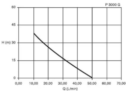
line
P 3000 G | Q (L/min) | H (m) | | :--- | :--- | | 10,00 | 32 | | 50,00 | 0 |(Pump characteristic curve for 0.5 m suction head and 1" suction hose.)
Commissioning

Note:
This pumps runs as long as the ON/OFF switch is switched ON.
- Plug power cable in.
- Switch pump on with the ON/OFF switch.
- Open pressure line (open tap or spray nozzle).
- Check to see that the water comes out!

Caution!
With a closed pressure line do not let pump run for more then 10 minutes, otherwise there could be
damage by the water overheating in the pump.
7. Care and Maintenance

Danger!
Prior to all servicing:
- Switch Off.
- Unplug.
- Ensure that pressure is relieved from equipment and connected accessories.
Service and repair work other than described here must be left to qualified specialists.
7.1 Danger of freezing

Caution!
Frost damages the pump and accessories, as both always contain water!
- When there is danger of freezing, dismount equipment and accessories and store at a freeze-proof location (see below).
7.2 Equipment dismounting and storing
- Switch equipment OFF and unplug.
- Open pressure line (open tap or spray nozzle) and drain water completely.
- Drain pump completely; to do so remove the drain plug from the pump
- Disconnect suction and pressure lines from the equipment.
- Store equipment in a frost-free space (at least 5 °C).
8. Trouble Shooting

Danger!
Prior to all servicing:
- Switch Off.
- Unplug.
- Ensure that pressure is relieved from equipment and connected accessories.
8.1 Fault finding
Pump does not run:
- No mains voltage.
- Check cables, plug, outlet and mains fuse.
– Mains voltage too low. - Use only extension cables with sufficient lead cross section (see "Technical Specifications").
-
Motor overheated, motor protection relay tripped.
• After cooling off the pump will switch ON again. -
Ensure sufficient ventilation, keep vent slots clear.
- Observe max. temperature of the pumped medium.
- Motor hums but does not start.
- With the motor switched OFF, put screwdriver or similar through the fan cover's vent slots and turn the fan.
- Pump blocked or out of order.
- Disassemble pump and clean.
- Clean diffusor, replace if necessary.
- Clean impeller, replace if necessary.
Pump does not prime correctly or runs very noisily:
– Lack of water.
- Ensure there is a sufficient water supply.
- Suction line leaky.
- Seal suction line, tighten screw fittings.
– Suction head too high.
- Observe max. suction head.
• Install check valve, fill suction line with water.
- Suction strainer (accessory) blocked.
- Clean, replace if necessary.
– Check valve (accessory) blocked.
- Clean, replace if necessary.
– Water leaks between motor and pump, Ducone seal worn.
- Replace Ducone seal.
– Pump blocked or out of order.
- see above.
Pressure too low:
- Suction line leaky or too much suction head.
- see above.
- Pump blocked or out of order.
- see above.
9. Repairs
Danger! Repairs
Repairs to electric tools must only be carried out by a qualified electrician!
Electric tools in need of repair can be sent to an authorised service center in your country. See spare parts list for address.
Please attach a description of the fault to the electric tool.
10. Environmental Protection
The packaging of the pump can be 100% recycled.
Worn out power tools and accessories contain considerable amounts of valuable raw and plastic materials, which can be recycled.
11. Available Accessories
For this equipment the following – and further – accessories are available at specialist dealers.
A Sto ck no. 090 304 0521: Pump Installation Package, complete with double nipple, check valve, filter short, washable filter cartridge, spiral hose assembly 1 m, thread sealing tape.
B Sto ck no. 090 306 3238: Hydromat HM 2, 230 V for automatic starting when water is drawn and stopping when no water is drawn, keeps the pump from running dry.
C Sto ck no. 090 305 2597: Hydrostop, 230 V for automatic stopping when there
is a lack of water, prevents the pump from running dry.
D Sto ck no. 090 302 8521: Dry-running Stop Switch, 230 V with 10 m cable, keeps the pump from running dry when pumping from tank, pool, etc.
E Sto ck no. 090 300 4258: Spiral Suction Hose 1", 4 m, c/w quick release screw fitting and strainer with foot valve;
Stock no. 090 301 1858: Spiral Suction Hose 1", 7 m, c/w quick release screw fitting and strainer with foot valve;
F Sto ck no. 090 302 8351: Disposable Filter Cartridge, long; Stock no. 090 302 8432: Disposable Filter Cartridge, short; for mechanical prefiltering of sand.
G Stock no. 090 302 8360: Washable Filter Cartridge, long; Stock no. 090 302 8440: Washable Filter Cartridge, short; for mechanical prefiltering of sand, reusable.
H Sto ck no. 090 301 6817: Pipe Nipple 150 mm, 1" male at both ends, galvanized, to connect pump and filter.
I Sto ck no. 090 301 8402: Double Nipple, 1" male at boths ends.
J Sto ck no. 090 302 8203: Check Valve 1" female, prevents water backflow and pump running dry.
K Sto ck no. 090 102 6319: Thread Sealing Tape, 12 m roll.
(AG=male, IG=female)
12. Technical Specifications
| Mains voltage | V | 230 ~ 1 | 110 ~ 1 |
| Frequency Hz 50 60 | |||
| Rated output | W | 900 | 950 |
| Rated current | A | 3.7 | 9.7 |
| Fuse protection min. (time-lag or L-type circuit breaker) | A | 10 | 15 |
| Running capacitor | μF | 16 | 35 |
| Rated speed | min^-1 | 2900 | 3400 |
| Pump capacity max. | l/h | 3000 | 3000 |
| Delivery head max. | m | 43 | 43 |
| Delivery pressure max. | bar | 4.3 | 4.3 |
| Max. suction head | m | 8.5 | 8.5 |
| Temperature of the primed medium max. | °C | 35 | 35 |
| Ambient temperature | °C | 5 ... 40 | 5 ... 40 |
| Degree of protection | IP X4 | IP X4 | |
| Protection class | I | I | |
| Insulation class | B | B | |
| Materials | |||
| Pump casing | Grey cast iron | Grey cast iron | |
| Pump shaft | Stainless steel | Stainless steel | |
| Impeller | Noryl | Noryl | |
| Connections (IG=female thread) | |||
| Pump inlet | 1" IG | 1" IG | |
| Discharge port | 1" IG | 1" IG | |
| Dimensions (without connections) | |||
| Length | mm | 375 | 375 |
| Width | mm | 185 | 185 |
| Height | mm | 250 | 250 |
| Weights | |||
| Dry weight | kg | 14.0 | 14.0 |
| Weight filled with water | kg | 14.5 | 14.5 |
| Noise emission values (at max. pressure) | |||
| Sound power level L_WAd | dB (A) | 75.0 | 75.0 |
| Max. length of extension cable | |||
| at 3 x 1.0 mm2 lead cross-section | m | 30 | 10 |
| at 3 x 1.5 mm2 lead cross-section | m | 50 | 20 |
– Pomp verstopt of defect.
- Demonteer de pomp en reinig ze.
- Diffusor reinigen, evt. vervangen.
- Loopwiel reinigen, evt. vervangen.
– Pomp verstopt of defect.
- zie hoger.
Druk te laag:
1 Strømkabel med stik
2 Pumpe
3 Vandaftapningsskrue
4 Indsugningstilslutning
5 Vandpåfyldningsskrue
6 Tilslutning af tryk
7 Start-/Stop-kontakt

line
| Q (L/min) | H (m) | | --------- | ----- | | 10 | 32 | | 50 | 0 |

- DE EN
- NL
- Table of Contents
- Please Read First!
- Range of Application and Pumping Media
- Safety
- Specified conditions of use
- General safety instructions
- Hazard by ambient conditions!
- Danger: Hot water!
- Danger! Risk of electric shock!
- Danger by pump failures!
- Caution!
- Prior to Operation
- Installation
- Suction line connection
- Note:
- Discharge port
- Danger!
- Mains connection
- Filling the pump and priming
- Operation
- Pump characteristic curve
- Commissioning
- Care and Maintenance
- Danger of freezing
- Equipment dismounting and storing
- Trouble Shooting
- Fault finding
- Pump does not run:
- Pump does not prime correctly or runs very noisily:
- Pressure too low:
- Repairs
- Danger! Repairs
- Environmental Protection
- Available Accessories
- Technical Specifications
- Druk te laag:
Brand : METABO
Model : P 3000 G
Category : Pump