GBH 224 RE Professional - Hammer BOSCH - Free user manual and instructions
Find the device manual for free GBH 224 RE Professional BOSCH in PDF.
| Product type | Rotary hammer |
| Brand | Bosch |
| Model | GBH 224 RE Professional |
| Reference number | 3611 B72 0.. |
| Rated power input | 790 W |
| Rated voltage | 230 V |
| Impact rate | 0 – 4,200 min⁻¹ |
| Impact energy (according to EPTA 05:2016) | 2.7 J |
| Rated speed | 0 – 930 rpm |
| Tool holder | SDS-plus |
| Max. drilling diameter in concrete | 24 mm |
| Max. drilling diameter in steel | 13 mm |
| Max. drilling diameter in wood | 30 mm |
| Max. drilling diameter in masonry (core bit) | 68 mm |
| Weight | 2.8 kg |
| Sound pressure level | 93 dB(A) |
| Sound power level | 104 dB(A) |
| Vibration (drilling in concrete) | 19.3 m/s² |
| Vibration (chiselling) | 10.7 m/s² |
| Functions | Drilling with impact, drilling without impact, chiselling, screwdriving (with reversibility) |
| Safety | Safety clutch, dust protection cap, adjustable auxiliary handle |
| Maintenance | Clean ventilation slots, replace dust protection cap if damaged |
| Spare parts and accessories | SDS-plus chuck, keyed chuck, extraction set, auxiliary handle, dust protection cap |
Frequently Asked Questions - GBH 224 RE Professional BOSCH
User questions about GBH 224 RE Professional BOSCH
0 question about this device. Answer the ones you know or ask your own.
Ask a new question about this device
Download the instructions for your Hammer in PDF format for free! Find your manual GBH 224 RE Professional - BOSCH and take your electronic device back in hand. On this page are published all the documents necessary for the use of your device. GBH 224 RE Professional by BOSCH.
USER MANUAL GBH 224 RE Professional BOSCH
2-24 RE|2-24 DRE|2-24DFR
Robert Bosch Power Tools GmbH
70538 Sutpart
GERMANY
www.bosch-pt.com
160992A77M[2021.12]PS/87

1609 92A 77M
en Original Instructions
fr Notice originale
pt Manual original
zh正本使用说明书
zh原始使用说明见
ko
th mivagamrnnn
A
id Petunjuk Petunjuk untuk
Penggunaan Original
Ban goc hong dan sordung
ar 1
fa

2
English Page 6
Francais.. Page 12
Portugues. Pagina 20
中文 页28
繁體中文. 33
39
Inu 46
General Power Tool SafetyWarnings
WARNING
Read all safety warnings, instructions, illustrations and specifica
tions provided with this power tool. Failure to follow all instructions listed below may result in electric shock, fire and/ or serious injury.
Save all warnings and instructions for future reference.
The term "power tool" in the warnings refers to your mains-operated (corded) power tool or battery-operated (cordless) power tool.
Work area safety
- Keep work area clean and well lit. Cluttered or dark areas invite accidents.
Do not operate power tools in explosive atmospheres, such as in the presence of flammable liquids, gases or dust. Power tools create sparks which may ignite the dust or fumes. - Keep children and bystanders away while operating a power tool. Distractions can cause you to lose control.
Electrical safety
Power tool plugs must match the outlet. Never modify the plug in any way. Do not use any adapter plugs with earthed (grounded) power tools. Unmodified plugs and matching outlets will reduce risk of electric shock.
- Avoid body contact with earthed or grounded surfaces, such as pipes, radiators, ranges and refrigerators. There is an increased risk of electric shock if your body is earthed or grounded.
Do not expose power tools to rain or wet conditions. Water entering a power tool will increase the risk of electric shock.
Do not abuse the cord. Never use the cord for carrying, pulling or unplugging the power tool. Keep cord away from heat, oil, sharp edges or moving parts. Damaged or entangled cords increase the risk of electric shock.
When operating a power tool outdoors, use an extension cord suitable for outdoor use. Use of a cord suitable for outdoor use reduces the risk of electric shock.
If operating a power tool in a damp location is unavoidable, use a residual current device (RCD) protected supply. Use of an RCD reduces the risk of electric shock.
Personal safety
Stay alert, watch what you are doing and use common sense when operating a power tool. Do not use a power tool while you are tired or under the influence of drugs, alcohol or medication. A moment of inatten
tion while operating power tools may result in serious personal injury.
Use personal protective equipment. Always wear eye protection. Protective equipment such as a dust mask, non-skid safety shoes, hard hat or hearing protection used for appropriate conditions will reduce personal injuries.
Prevent unintentional starting. Ensure the switch is in the off-position before connecting to power source and/or battery pack, picking up or carrying the tool. Carrying power tools with your finger on the switch or energising power tools that have the switch on invites accidents.
- Remove any adjusting key or wrench before turning the power tool on. A wrench or a key left attached to a rotating part of the power tool may result in personal injury.
Do not overreach. Keep proper footing and balance at all times. This enables better control of the power tool in unexpected situations.
Dress properly. Do not wear loose clothing or jewellery. Keep your hair and clothing away from moving parts. Loose clothes, jewellery or long hair can be caught in moving parts.
If devices are provided for the connection of dust extraction and collection facilities, ensure these are connected and properly used. Use of dust collection can reduce dust-related hazards.
Do not let familiarity gained from frequent use of tools allow you to become complacent and ignore tool safety principles. A careless action can cause severe injury within a fraction of a second.
Power tool use and care
Do not force the power tool. Use the correct power tool for your application. The correct power tool will do the job better and safer at the rate for which it was designed.
- Do not use the power tool if the switch does not turn it on and off. Any power tool that cannot be controlled with the switch is dangerous and must be repaired.
- Disconnect the plug from the power source and/or remove the battery pack, if detachable, from the power tool before making any adjustments, changing accessories, or storing power tools. Such preventive safety measures reduce the risk of starting the power tool accidentally.
- Store idle power tools out of the reach of children and do not allow persons unfamiliar with the power tool or these instructions to operate the power tool. Power tools are dangerous in the hands of untrained users.
- Maintain power tools and accessories. Check for misalignment or binding of moving parts, breakage of parts and any other condition that may affect the power tool's operation. If damaged, have the power tool repaired before use. Many accidents are caused by poorly maintained power tools.
- Keep cutting tools sharp and clean. Properly maintained cutting tools with sharp cutting edges are less likely to bind and are easier to control.
Use the power tool, accessories and tool bits etc. in accordance with these instructions, taking into account the working conditions and the work to be performed. Use of the power tool for operations different from those intended could result in a hazardous situation. - Keep handles and grasping surfaces dry, clean and free from oil and grease. Slippery handles and grasping surfaces do not allow for safe handling and control of the tool in unexpected situations.
Service
Have your power tool serviced by a qualified repair person using only identical replacement parts. This will ensure that the safety of the power tool is maintained.
Hammer SafetyWarnings
Safety instructions for all operations
Wear ear protectors. Exposure to noise can cause hearing loss.
Use auxiliary handle(s), if supplied with the tool. Loss of control can cause personal injury.
Hold the power tool by insulated gripping surfaces, when performing an operation where the cutting accessory or fasteners may contact hidden wiring or its own cord. Cutting accessory or fasteners contacting a "live" wire may make exposed metal parts of the power tool "live" and could give the operator an electric shock.
Safety instructions when using long drill bits with rotary hammers
Always start drilling at low speed and with the bit tip in contact with the workpiece. At higher speeds, the bit is likely to bend if allowed to rotate freely without contacting the workpiece, resulting in personal injury.
Apply pressure only in direct line with the bit and do not apply excessive pressure. Bits can bend, causing breakage or loss of control, resulting in personal injury.
Additional safety information
Use suitable detectors to determine if utility lines are hidden in the work area or call the local utility company for assistance. Contact with electric lines can lead to fire and electric shock. Damaging a gas line can lead to explosion. Penetrating a water line causes property damage or may cause an electric shock.
Always wait until the power tool has come to a complete stop before placing it down. The application tool can jam and cause you to lose control of the power tool.
- Secure the workpiece. A workpiece clamped with clamping devices or in a vice is held more secure than by hand.
Products sold in GB only:
Your product is fitted with an BS 1363/A approved electric plug with internal fuse (ASTA approved to BS 1362).
If the plug is not suitable for your socket outlets, it should be cut off and an appropriate plug fitted in its place by an authorised customer service agent. The replacement plug should have the same fuse rating as the original plug. The severed plug must be disposed of to avoid a possible shock hazard and should never be inserted into a mains socket elsewhere.
Do not touch any application tools or adjacent housing components shortly after operation. These can become very hot during operation and cause burns.
The application tool may jam during drilling. Make sure you have a stable footing and hold the power tool firmly with both hands. Otherwise you could lose control of the power tool.
Take care when carrying out demolition work using the chisel. Falling fragments of the demolition material could injure you or any bystanders.
Hold the power tool firmly with both hands and make sure you have a stable footing. The power tool can be more securely guided with both hands.
Product Description and Specifications

Read all the safety and general instructions. Failure to observe the safety and general instructions may result in electric shock, fire and/or serious injury.
Please observe the illustrations at the beginning of this operating manual.
Intended Use
GBH2-24RE
The power tool is intended for hammer drilling in concrete, brick and stone. It is also suitable for drilling without impact in wood, metal, ceramic and plastic. Power tools with electronic control and right/left rotation are also suitable for screwdriving.
GBH 2-24DRE, GBH 2-24DFR
The power tool is intended for hammer drilling in concrete, brick and stone, as well as for light chiselling work. It is also suitable for drilling without impact in wood, metal, ceramic and plastic. Power tools with electronic control and right/left rotation are also suitable for screwdriving.
Product Features
The numbering of the product features refers to the diagram of the power tool on the graphics page.
(1)Keyless quick-change chuck (GBH 2-24 DFR)
(2) SDS plus quick-change chuck (GBH 2-24 DFR)
(3) SDS plus tool holder
(4) Dust protection cap
(5) Locking sleeve
(6) Locking ring for quick-change chuck (GBH 2-24 DFR)
8 | English
(7) Rotational direction switch
(8) Lock-on button for on/off switch
(9) On/off switch
(10) Release button for impact/mode selector switch (GBH 2-24 DRE, GBH 2-24 DFR)
(11) Impact/mode selector switch (GBH 2-24 DRE, GBH 2-24 DFR)
(12) Button for depth stop adjustment
(13) Depth stop
(14) Auxiliary handle (insulated gripping surface)
(15) Release button for "drilling/hammer drilling" selector switch (GBH 2-24 RE)
(16) "Drilling/hammer drilling" selector switch (GBH 2-24 RE)
(17) Handle (insulated gripping surface)
(18) Securing screw for keyed chuck
(19) Keyed chucka)
(20) SDS plus shank for drill chuck
(21) Drill chuck holder (GBH 2-24 DFR)
(22) Front sleeve of the keyless quick-change chuck (GBH 2-24 DFR)
(23) Retaining ring of the keyless quick-change chuck (GBH 2-24 DFR)
(24) Saugfix suction openinga
(25) Saugfix clamping screw
(26) Saugfix depth stop
(27) Saugfix telescopic tube
(28) Saugfix wing bolt
(29) Saugfix guide tube a
(30) Universal holder with SDS plus shanka
a) Accessories shown or described are not included with the product as standard. You can find the complete selection of accessories in our accessories range.
Technical Data
Rotary hammer GBH 2-24 RE GBH 2-24 DRE GBH 2-24 DFR
| Article number | 3611 B720..3611 B72 1..3611 B730.. | |||
| Speed control●●● | ||||
| Stop rotation-●● | ||||
| Clockwise/anticlockwise rotation●●● | ||||
| Quick-change chuck--● | ||||
| Rated power input W 790 790 790 | ||||
| Impact rate min | 1 | 0-4200 0-4200 0-4200 | ||
| Impact energy per stroke accord-ing to EPTA-Procedure 05:2016 | J 2.7 2.7 2.7 | |||
| Rated speed min | 1 | 0-930 | 0-930 | 0-930 |
| Tool holder | SDS plus | SDS plus | SDS plus | |
| Spindle collar diameter | mm | 48.5 | 48.5 | 48.5 |
| Max. drilling diameter | ||||
| Concrete | mm | 24 | 24 | 24 |
| Masonry (with hollow core bit) | mm | 68 | 68 | 68 |
| Steel | mm | 13 | 13 | 13 |
| Wood | mm | 30 | 30 | 30 |
| Weight according to EPTA-Pro-cEDURE 01:2014 | kg 2.8 2.8 2.9 | |||
| Protection class | ☐/II | ☐/II | ☐/II | |
The specifications apply to a rated voltage [U] of 230 V. These specifications may vary at different voltages and in country-specific models.
Noise/Vibration Information
Noise emission values determined according to ENIEC 62841-2-6.
Typically, the A-weighted noise level of the power tool is: Sound pressure level 93 dB(A); sound power level 104 dB(A). Uncertainty K = 3 dB.
Wear hearing protection!
Vibration total values a_h (triax vector sum) and uncertainty K determined according to EN IEC 62841-2-6:
Hammer drilling into concrete: a_n = 19.3 m/s^2, K = 1.5 m/s^2 , Chiselling: a_n = 10.7 m/s^2, K = 1.5 m/s^2
The vibration level and noise emission value given in these instructions have been measured in accordance with a standardised measuring procedure and may be used to com
pare power tools. They may also be used for a preliminary estimation of vibration and noise emissions.
The stated vibration level and noise emission value represent the main applications of the power tool. However, if the power tool is used for other applications, with different application tools or is poorly maintained, the vibration level and noise emission value may differ. This may significantly increase the vibration and noise emissions over the total working period.
To estimate vibration and noise emissions accurately, the times when the tool is switched off or when it is running but not actually being used should also be taken into account. This may significantly reduce vibration and noise emissions over the total working period.
Implement additional safety measures to protect the operator from the effects of vibration, such as servicing the power tool and application tools, keeping their hands warm, and organising workflows correctly.
Assembly
Pull the plug out of the socket before carrying out any work on the power tool.
Auxiliary handle
Do not operate your power tool without the auxiliary handle (14).
Make sure that the auxiliary handle is always tightened. Otherwise you could lose control of the power tool when working.
Swivelling the auxiliary handle (see figure A)
You can swivel the auxiliary handle (14) to any angle for a safe work posture that minimises fatigue.
- Turn the lower gripping end of the auxiliary handle (14) anticlockwise and swivel the auxiliary handle (14) into the required position. Then turn the lower gripping end of the auxiliary handle (14) clockwise to retighten it. Make sure that the retaining strap of the auxiliary handle slots into the corresponding groove of the housing.
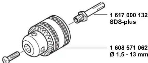
Selecting drill chucks and tools
Hammer drilling and chiselling require SDS-plus application tools that are inserted into the SDS-plus drill chuck.
For drilling without impact in wood, metal, ceramic and plastic as well as for screwdriving, tools without SDS-plus are used (e.g. cylindrical shank drill bits). For these tools, a keyless chuck or a keyed chuck are required.
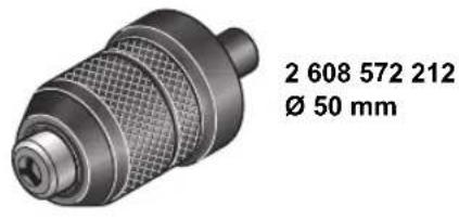
GBH 2-24 DFR: The SDS plus quick-change chuck (2) can easily be swapped with the keyless quick-change chuck (1) supplied.
Changing the drill chuck
Inserting/removing the keyed chuck
GBH 2-24 RE, GBH 2-24 DRE
You must use a suitable drill chuck (keyed or keyless chuck, accessories) to work with tools that do not have SDS-plus (e.g. cylindrical shank drill bits).
Fitting the keyed chuck (see figure B)
Screw the SDS-plus shank (20) into a keyed chuck (19). Secure the keyed chuck (19) using the securing screw (18). Note that the securing screw has a left-hand thread.
Inserting the keyed chuck (see figure B)
- Clean and lightly grease the insertion end of the shank.
- Insert the keyed chuck with the adapter shank into the tool holder with a turning motion until it automatically locks.
- Check that it is locked by pulling the keyed chuck.
Removing the keyed chuck
- Push the locking sleeve (5) back and remove the keyed chuck (19).
Removing/inserting the quick-change chuck
GBH2-24DFR
Removing the Quick-Change Chuck (see figure C)
- Pull back on the quick-change chuck locking ring (6), hold it in this position and pull the SDS plus quick-change chuck (2) or the keyless quick-change chuck (1) out from the front.
- Once the quick-change chuck is removed, protect it from dirt.
Inserting the Quick-Change Chuck (see figure D)
Before insertion, clean the quick-change chuck and lightly grease the shank.
- Wrap your whole hand around the SDS plus quick-change chuck (2) or the keyless quick-change chuck (1). Use a turning motion to push the quick-change chuck into the drill chuck holder (21) until you hear it click into place.
- The quick-change chuck is automatically locked. Check that it is locked by pulling on the quick-change chuck.
Changing the Tool
The dust protection cap (4) largely prevents the penetration of drilling dust into the tool holder during operation. When inserting the tool, make sure that the dust protection cap (4) does not become damaged.
Replace a damaged dust protection cap immediately. It is recommended that you have use an after-sales service for this.
Changing the tool (SDS plus)
Inserting SDS plus application tools (see figure E)
The SDS-plus drill chuck enables you to change the application tool easily and conveniently without needing to use additional tools.
- GBH 2-24 DFR: Insert the SDS plus quick-change chuck (2).
10 | English
- Clean and lightly grease the shank of the application tool.
- Insert the application tool into the tool holder while turning it until it locks automatically.
- Check that it is locked by pulling on the tool.
As a requirement of the system, the SDS-plus application tool can move freely. This causes a certain radial run-out at no-load, which has no effect on the accuracy of the drill hole, as the drill bit centres itself upon drilling.
Removing SDS-plus application tools (see figure F)
- Push the locking sleeve (5) back and remove the application tool.
Changing the keyed chuck
GBH 2-24 RE, GBH 2-24 DRE
Inserting the Application Tool
Note: Application tools that do not have SDS plus must not be used for hammer drilling or chiselling. Tools without SDS plus and their drill chucks are damaged by hammer drilling or chiselling.
- Insert a keyed chuck (19).
- Open the keyed chuck (19) by turning it until the tool can be inserted. Insert the tool.
- Insert the chuck key into the corresponding holes of the keyed chuck (19) and clamp the tool evenly.
- GBH 2-24 RE: Set the selector switch (16) to the "drilling" symbol.
- GBH 2-24 DRE: Turn the impact/mode selector switch (11) to the "drilling" position.
Removing the application tool
- Use the chuck key to turn the sleeve of the keyed chuck (19) anticlockwise until the application tool can be removed.
Changing the keyless quick-change chuck
GBH2-24DFR
Inserting the application tool (see figure G)
Note: Application tools that do not have SDS plus must not be used for hammer drilling or chiselling. Tools without SDS plus and their drill chucks are damaged by hammer drilling or chiselling.
- Insert the keyless quick-change chuck (1).
- Hold the retaining ring (23) of the keyless quick-change chuck firmly in place. Open the tool holder by turning the front sleeve (22) until the tool can be inserted. Hold the retaining ring (23) in place and firmly tighten the front sleeve (22) by turning it in the direction of the arrow until you hear it click into place.
- Check that it is seated securely by pulling on the tool.
Note: If the tool holder was unscrewed all the way, a scraping sound may be heard while retightening the tool holder and it may not fully tighten.
In this case, turn the front sleeve (22) in the opposite direction to the arrow by one full turn. This will allow the tool holder to be fully tightened.
- Turn the impact/mode selector switch (11) to the "drilling" position.
Removing the application tool (see figure H)
Hold the retaining ring (23) of the keyless quick-change chuck firmly in place. Open the tool holder by turning the front sleeve (22) in the direction of the arrow until the tool can be removed.
Dust/Chip Extraction
The dust from materials such as lead paint, some types of wood, minerals and metal can be harmful to human health. Touching or breathing in this dust can trigger allergic reactions and/or cause respiratory illnesses in the user or in people in the near vicinity.
Certain dusts, such as oak or beech dust, are classified as carcinogenic, especially in conjunction with wood treatment additives (chromate, wood preservative). Materials containing asbestos may only be machined by specialists.
- Use a dust extraction system that is suitable for the material wherever possible.
- Provide good ventilation at the workplace.
- It is advisable to wear a P2 filter class breathing mask.
The regulations on the material being machined that apply in the country of use must be observed.
- Avoid dust accumulation at the workplace. Dust can easily ignite.
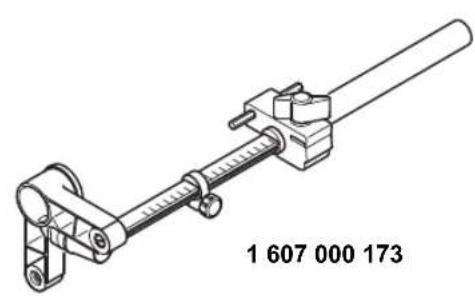
Dust extraction with the dust extraction attachment (accessory)
Fitting the dust extraction attachment (see figure I)
For dust extraction, the dust extraction attachment (accessory) is required. When drilling, the dust extraction attachment retracts so that the attachment head is always close to the surface at the drill hole.
- Press the button for depth stop adjustment (12) and remove the depth stop (13). Press the button (12) again and insert the dust extraction attachment into the auxiliary handle (14) from the front.
- Connect an extraction hose (diameter 19 mm, accessory) to the suction opening (24) of the dust extraction attachment.
The dust extractor must be suitable for the material being worked.
When extracting dust that is dry, especially detrimental to health or carcinogenic, use a special dust extractor.
Setting the drilling depth on the dust extraction attachment (see figure J)
You can also set the required drilling depth X when the dust extraction attachment is fitted.
- Push the SDS-plus application tool into the SDS-plus tool holder (3) as far as it will go. Otherwise, the movability of the SDS-plus drilling tool can lead to incorrect adjustment of the drilling depth.
- Loosen the wing bolt (28) on the dust extraction attachment.
-
Without switching it on, press the power tool firmly against the surface you wish to drill. The SDS-plus application tool must be touching the surface.
-
Position the guide tube (29) of the dust extraction attachment in its holder such that the head of the dust extraction attachment rests on the surface to be drilled. Do not slide the guide tube (29) further than necessary over the telescopic tube (27), so that as much as possible of the scale remains visible on the telescopic tube (27).
- Retighten the wing bolt (28). Loosen the clamping screw (25) on the depth stop of the dust extraction attachment.
- Slide the depth stop (26) onto the telescopic tube (27) so that the distance X shown in the illustration matches your required drilling depth.
- Tighten the clamping screw (25) in this position.
Operation
▶ Products that are only sold in AUS and NZ: Use a residual current device (RCD) with a nominal residual current of 30 mA or less.
Start-up
Pay attention to the mains voltage. The voltage of the power source must match the voltage specified on the rating plate of the power tool. Power tools marked with 230V can also be operated with 220V .
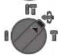
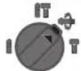
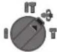
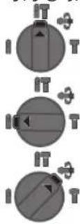
Setting the Operating Mode
GBH 2-24 RE:
Use the "drilling/hammer drilling" selector switch (16) to select the power tool's operating mode.
- To change the operating mode, press the release button (15) and turn the "drilling/hammer drilling" selector switch (16) until it clicks into the required position.
Note: Only change the operating mode when the power tool is switched off. Otherwise, the power tool may become damaged.
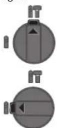
Position for hammer drilling into concrete or stone
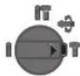
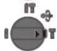
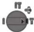
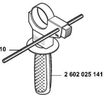
GBH 2-24 DRE, GBH 2-24 DFR:
The operating mode of the power tool is selected using the impact/mode selector switch (11).
- To change the operating mode, press the release button (10) and turn the impact/mode selector switch (11) until it clicks into the required position.
Note: Only change the operating mode when the power tool is switched off. Otherwise, the power tool may become damaged.
Position for hammer drilling into concrete or stone

Position for drilling without impact in wood, metal, ceramic and plastic and for screwdriving
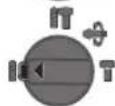
Vario-Lock position for adjusting the chisel position
The impact/mode selector switch (11) will not engage in this position.
Position for chiselling
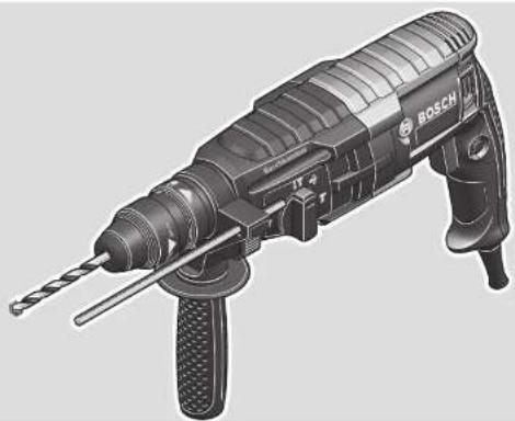
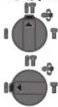
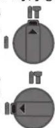
Setting the Rotational Direction
The rotational direction switch (7) is used to change the rotational direction of the power tool. However, this is not possible while the on/off switch (9) is being pressed.
Only operate the rotational direction switch (7) when the power tool is not in use.
Always set the rotational direction to clockwise rotation for hammer drilling, drilling and chiselling.
- Rotate clockwise: Turn the rotational direction switch (7) on both sides until it stops in the position.
- Rotate anticlockwise: Turn the rotational direction switch (7) on both sides until it stops in the position.
Switching On/Off
- To switch on the power tool, press the on/off switch (9).
- To lock the on/off switch (9), press and hold it while also pushing the lock-on button (8).
- To switch off the power tool, release the on/off switch (9). If the on/off switch (9) is locked, press the switch first and then release it.
Adjusting the Speed/Impact Rate
You can adjust the speed/impact rate of the power tool when it is on by pressing in the on/off switch (9) to varying extents.
Applying light pressure to the on/off switch (9) results in a low rotational speed/impact rate. Applying increasing pressure to the switch increases the speed/impact rate.
Changing the chiselling position (Vario-Lock)
GBH 2-24 DRE, GBH 2-24 DFR
You can lock the chisel in 36 different positions, so you can select the optimum working position for each task.
- Insert the chisel into the tool holder.
- Turn the impact/mode selector switch (11) to the "VarioLock" position.
- Turn the application tool to the required chisel position.
- Turn the impact/mode selector switch (11) to the "chiselling" position. With this, the tool holder is locked.
- Set the rotational direction for chiselling to clockwise.
Practical Advice
Setting the drilling depth (see figure K)
You can use the depth stop (13) to set the required drilling depth X .
12 | Français
- Press the button for depth stop adjustment (12) and insert the depth stop into the auxiliary handle (14). The fluting on the depth stop (13) must face downwards.
- Insert the SDS-plus application tool into the SDS-plus tool holder (3) to the stop. Otherwise, the movability of the SDS-plus drilling tool can lead to incorrect adjustment of the drilling depth.
- Pull the depth stop far enough out that the distance between the drill bit tip and the edge of the depth stop corresponds to the required drilling depth X.
Overload clutch
If the application tool jams or snags, the power transmission to the drill spindle will be interrupted. Always hold the power tool firmly with both hands to withstand the forces this may create and adopt a position with stable footing.
- Switch the power tool off immediately and remove the application tool if the power tool becomes blocked. Switching on when the drilling tool is blocked may cause high torque reactions.
Inserting screwdriver bits (see figure L)
Only apply the power tool to the screw/nut when the tool is switched off. Rotating tool inserts can slip off.
A universal holder (30) with SDS-plus shank (accessory) is required to work with screwdriver bits.
- Clean and lightly grease the insertion end of the shank.
- Insert the universal holder into the tool holder while turning it until it locks automatically.
- Check that it is locked by pulling the universal holder.
- Insert a screwdriver bit in the universal holder. Only use screwdriver bits that fit the screw head.
- To remove the universal holder, slide the locking sleeve (5) backwards and remove the universal holder (30) from the tool holder.
Maintenance and Service
Maintenance and Cleaning
Pull the plug out of the socket before carrying out any work on the power tool.
To ensure safe and efficient operation, always keep the power tool and the ventilation slots clean.
In order to avoid safety hazards, if the power supply cord needs to be replaced, this must be done by Bosch or by an after-sales service centre that is authorised to repair Bosch power tools.
Replace a damaged dust protection cap immediately. It is recommended that you have use an after-sales service for this.
Clean the tool holder (3) after each use.
After-Sales Service and Application Service
Our after-sales service responds to your questions concerning maintenance and repair of your product as well as spare
parts. You can find explosion drawings and information on spare parts at: www.bosch-pt.com
The Bosch product use advice team will be happy to help you with any questions about our products and their accessories.
In all correspondence and spare parts orders, please always include the 10-digit article number given on the nameplate of the product.
Malaysia
Robert Bosch Sdn. Bhd.(220975-V) PT/SMY
No.8A,Jalan 13/6
46200 Petaling Jaya
Selangor
Tel.: (03) 79663194
Toll-Free: 1800 880188
Fax: (03) 79583838
E-Mail: kiathoe.chong@my.bosch.com
www.bosch-pt.com.my
You can find further service addresses at:
www.bosch-pt.com/serviceaddresses
Disposal
The power tool, accessories and packaging should be recycled in an environmentally friendly manner.
Do not dispose of power tools along with household waste.
Français
GBH 2-24 DRE, GBH 2-24 DFR
Marteau perforatoreg BH 2-24 RE GBH 2-24 DRE GBH 2-24 DFR
Poids selon EPTA:Procedure 01:2014
kg2,82,82,9
Indices de protection
回/Ⅱ/Ⅱ/Ⅱ
回
回
GBH 2-24 RE, GBH 2-24 DRE
GBH 2-24 RE, GBH 2-24 DRE
Robert Bosch Morocco SARL
53, Rue Lieutenant Mahmoud Mohamed
20300 Casablanca
Tel.: +212 5 29 31 43 27
E-Mail: sav.outillage@ma.bosch.com
www.bosch-pt.com/serviceaddresses
GBH 2-24 DRE, GBH 2-24 DFR
GBH 2-24 RE, GBH 2-24 DRE
GBH 2-24 RE, GBH 2-24 DRE
GBH 2-24 DRE, GBH 2-24 DFR:
GBH 2-24 DRE, GBH 2-24 DFR
www.bosch-pt.com/serviceaddresses
Eliminação
GBH 2-24 DRE, GBH 2-24 DFR
GBH 2-24 RE, GBH 2-24 DRE
GBH 2-24 RE, GBH 2-24 DRE
安装工具刀头
GBH 2-24 DRE, GBH 2-24 DFR:
GBH 2-24 DRE, GBH 2-24 DFR
www.bosch-pt.com/serviceaddresses
处理废弃物
GBH 2-24 DRE, GBH 2-24 DFR
GBH 2-24 RE, GBH 2-24 DRE
GBH 2-24 RE, GBH 2-24 DRE
安装嵌件工具
GBH 2-24 DRE, GBH 2-24 DFR:
GBH 2-24 DRE, GBH 2-24 DFR
www.bosch-pt.com/serviceaddresses
廢棄物處理
GBH 2-24 DRE, GBH 2-24 DFR
GBH 2-24 RE, GBH 2-24 DRE
GBH 2-24 RE, GBH 2-24 DRE
音日公
志::
(22) 請諸國國國國國國國國國國國國國國國國國國國國國國國國國國國國國國國國國國國國國國國國國國國國國國國國國國國國國國國國國國國國國國國國國國國國國國國國國國國國國國國國國國國國國國國國國國國國國國國國國國國國国
(23) 論竊賊歟,賊賊是不,此之,此之,此之,此之,此之,此之,此之,此之,此之,此之,此之,此之,此之,此之,此之,此之,此之,此之,此之,此之,此之,此之,此之,此之,此之,此之,此之,此之,此之,此之,此之,此之,此之,此之
- bitr 1
GBH 2-24 DRE, GBH 2-24 DFR:
MOB3 11)
志::中,工。
克KRIE 无在电
GBH 2-24 DRE, GBH 2-24 DFR
36 wchset chcd to gctnslu.
www.bosch-pt.com/serviceaddresses
←
吉之
前通国公将告期用丛理为制
#
nssuwwaaan
n n"100000000000000000000000000000000000000000000000000000000000000000000000
aannnnnnae annnnnnn
yauuunnuuunnuuulwunuunnuuunnuuunn uunnuuunnuuun
aalwannnnaanrnnnnae
nauuunnuuunnuu uuuuunnuunnuu uuuuunnuu uuuuunnuu uuuuunnuu uuuuunnuu uuuuunnuu uuuuunnuu uuuuunnuu uuuuunnuu uuuuunnuu uuuuunnuu uuuuunnuu uuuuunnuu uuuuunnuu uuuuunnuu uuuuunnuu uuuuunnuu uuuuunnuu
aannanenanaeauwlnnnaeauv 1nnnuuuaueauuauauauauauuuu uauauauauauauauuuuuuuuuuuuuuuuuuuuuuuuuuuuuuuuuuuuuuuuuuuuuuuuuuuuuuuuuuuuuuuuuuuuuuuuuuuuuuuuuuuuuuuuuuuuuuuuuuuuuuuuuuuuuuuuuuuuuuuuuuuuuuuuuuuuuuuuuuuuuuuuuuuuuuuuuuuuuuuuuuuuuuuuuuuuuuuuuuuuuuuuuuuuuuuuuuuuuuuuuUU
1 1
nnaananaananaananaananaananaananaananaananaananaananaananaananaananaananaananaananaananaananaananaananaananaananaananaananaananaananaananaananaananaananaananaananaananaananaananaananaananaananaananaananaananaananaananaananaananaananaananaananaananaananaanaraannnnnnnnnnnnnnnnnnnnnnnnnnnnnnnnnnnnnnnnnnnnnnnnnnnnnnnnnnnnnnnnnnnnnnnnnnnnnnnnnnnnnnnnnnnnnnnnnnnnnnnnnnnn
1 1
yuaanuuaaunnuuauuauauauauauauauauauauauuuuuuuuuuuuuuuuuuuuuuuuuuuuuuuuuuuuuuuuuuuuuuuuuuuuuuuuuuuuuuuuuuuuuuuuuuuuuuuuuuuuuuuuuuuuuuuuuuuuuuuuuuuuuuuuuuuuuuuuuuuuuuuuuuuuuuuuuuuuuuuuuuuuuuuuuuuuuuuuuuuuuuuuuuuuuuuuuuuuuuuuuuuuuuuuuuuuuuuuuUU
m
aalwauanuunnnaaannnnnnae
aannnnnnaanennnnnnnnn
H
aannnnnnuuunnuuau nnaanennnnnnnnnnnnnnnnnnnnnnnnnnnnnnnnnnnnnnnnnnnnnnnnnnnnnnnnnnnnnnnnnnnnnnnnnnnnnnnnnnnnnnnnnnnnnnnnnnnnnnnnnnnnnnnnnn
1
mnnnnaaannnnnnaanennnnae nnnnnnnnnnnnnnnnnnne nnnnnnnnnnnnnnnnnnne nnnnnnnnnnnnnnnnnnne nnnnnnnnnnnnnnnnne nnnnnnnnnnnnnnnnne nnnnnnnnnnnnnnne nnnnnnnnnnnnnnne nnnnnnnnnnnnne nnnnnn nnnee
Hnnnnaaannnnnnae nnnnnae
1
48|m
1 1
nunuunnuuaanuun
nnaananaananaananaananaananaananaananaananaananaananaananaananaananaananaananaananaananaananaananaananaananaananaananaananaananaananaananaananaananaananaananaananaananaananaananaananaananaananaananaananaananaananaananaananaananaananaananaananaananaananaanaraannnnnnnnnnnnnnnnnnnnnnnnnnnnnnnnnnnnnnnnnnnnnnnnnnnnnnnnnnnnnnnnnnnnnnnnnnnnnnnnnnnnnnnnnnnnnnnnnnnnnnnnnnnnnnnnnnnnnnnnnnnnnnnnnn
aaiinaiiiaaiinaiinaaaiinaiinaiinaiinai
Hnnn nnnnnnnnnnnnnnnnnnnnnnnnnnnnnnnnnnnnnnnnnnnnnnnnnnnnnnnnnnnnnnnnnnnnnnnnnnnnnnnnnnnnnnnnnnnnnnnnnnnnnnnnnnn
nnaaannnnnnaanennnnaan nnnnnnnnnaan
1 1
1
aunauuulnnuuunnuuunnuuunnuunnuunnuunnuunnuunnuunnuunnuunnuunnuunnuunnuunnuunnuunnuunnuunnuunnuunnuunnuunnuunnuunnuunnuunnuunnuunnuunnu
yua
#

aunnnnnaanannnnnnnnnnnnnnnnnnnnnnnnnnnnnnnnnnnnnnnnnnnnnnnnnnnnnnnnnnnnnnnnnnnnnnnnnnnnnnnnnnnnnnnnnnnnnnnnnnnnnnnnnnnnnnnnnnnnnnnnnnnnnnnnnnnnnnnnnnnnnnnnnnnnnnnnnnnnnnnnnn
aannnnnnaaananaananaananaananaananaananaananaananaananaananaananaananaananaananaananaananaananaananaananaananaananaananaananaananaananaananaananaananaananaananaananaananaananaananaananaananaananaananaananaananaananaananaananaananaananaananaananaananaananaananaanara an
GBH 2-24 DRE, GBH 2-24 DFR
nannnnnnaaannnnnnaa aannn nnnnnnnaaennnnnnaaannnnnnaaannnnnnaaannnnnnaaannnnnnaaannnnnnaaannnnnnaaannnnnnaaannnnnnaaannnnnnaaannnnnnaaannnnnnaaannnnnnaaannnnnnaaannnnnnaaannnnnnaaannnnnnaaannnnnnaaannnnnnaaannnnnnaaannnnnnaa annnnn
nwnnnn
nunnuuunnuuunnuunnuuuuuuuuuuuuuuuuuuuuuuuuuuuuuuuuuuuuuuuuuuuuuuuuuuuuuuuuuuuuuuuuuuuuuuuuuuuuuuuuuuuuuuuuuuuuuuuuuuuuuuuuuuuuuuuuuuuuuuuuuuuuuuuuuuuuuuuuuuuuuuuuuuuuuuuuuuuuuuuuuuuuuuuuuuuuuuuuuuuuuuuuuuuuuuuuuuuuuuuuuUU
GBH 2-24 DFR: #n SDs-plus (2) nnnn nn nn nn nn nn nn nn nn nn nn nn nn nn nn nn nn nn nn nn nn nn nn nn nn nn nn nn nn nn nn nn nn nn nn nn nn nn nn nn nn nn nn nn nn nn nn nn nn nn nn nn nn nn nn nn nn nn nn nn nn nn nn nn nn nn nn nn nn nn nn nn nn nn nn nn nn nn nn nn nn nn nn nn nn nn nn nn
nuaaunnae
nla/naanannnnnnnnnnnnnuu
GBH 2-24 RE, GBH 2-24 DRE
GBH 2-24 RE, GBH 2-24 DRE
muaiaov
HnH: 100000000000000000000000000000000000000000000000000000000000000000000
-
laiunanwuiwuju (19)
-
107n7n7n7n7n7n7n7n7n7n7n7n7n7n7n7n7n7n7n7n7n7n7n7n7n7n7n7n7n7n7n7n7n7n7n7n7n7n7n7n7n7n7n7n7n7n7n7n7n7n7
-1uuaanrannnunnuuauauauuuuauuauuauu uuuuauu (19) uauuuaa aauuunnnn
-GBH2-24RE:(16)yany"
-GBH2-24DRE:naaannnnnannn/nyannu (11)wnun "n
mnnnne
-
2nunnn (23) nnuuunnuuuuu uuuuunnuu (22) nuu uuuu uuuu uuuu uuuu (23) uuuu uuuuuaaannn (22) uuuuuuuuuuuuuuu
Hnnaa: nnaaannnnnnaanennnnaanennnnae
unuunnnnnaannn (22) ununnuunnuunnu
- nuaaannnnaan /nana (11) 1nnn "
mnnnnaovia (anwunnu H)
- 23242526272829202122232425262728292021223242526272829202122324252627282920212232425
nannnnnnae
mnnnnaaennnnnnnnnnnnnnnnnnnnnnnnnnnnnnnnnnnnnnnnnnnnnnnnnnnnnnnnnnnnnnnnnnnnnnnnnnnnnnnnnnnnnnnnnnnnnnnnnnnnnnnnnnnnnnnnnnnnnnnnnnnnnnnnnnnnnnnnnnnnnnnnnnnnnnnn
nann nnnn nn nnnn nnnn nnnn nnnn nnnn nnnn nnnn nnnn nnnn nnnn nnnn nnnn nnnn nnnn nnnn nnnn nnnn nnnn nnnn nnnn nnnn nnnn nnnn nnnn nnnn nnnn nnnn nnnn nnnn nnnn nnnn nnnn nnnn nnnn nn
-11111111111111111111 1
- yuuusunnnnnaaannnnnnaanennnnnnnnnnnnnnnnnnnnnnnnnnnnnnnnnnnnnnnnnnnnnnnnnnnnnnnnnnnnnnnnnnnnnnnnnnnnnnnnnnnnnnnnnnnnnnnnnnnnnnnnnnnnnnnnnnnnnnnnnnnnnnnnnnnnnnnn
GBH 2-24 DRE, GBH 2-24 DFR:
nwaunuva (Vario-Lock)
GBH 2-24 DRE, GBH 2-24 DFR
nnuanunanaanana 36 cnnuu luauunnu nnu
-nyuunnynnn/nyannu (11) Unncnun "Vario-Lock"
-nyuunyuyuuiyuoyuchununununun
-nyanmnyannn/nyannuu(11)luunnu "na"
-
yuaununrnu
muaaannnnnna (anwauuK)
nunnnnnnnnnnnnn (13) nannnnnnnnnnnnnn
- nuaaunuunnnaan (12) naan (14)
nunnnnunun (13)
-SDS-plus SDs-plus (3) SDS-plus
一
aannnnnnae
nnaaannnnnnaaennnnn nnnnnn nn nnnnnnnnnnnnnnnnnnnnnnnnnnnnnnnnnnnnnnnnnnnnnnnnnnnnnnnnnnnnnnnnnnnnnnnnnnnnnnnnnnnnnnnnnnnnnnnnnnnnnnnnnnnnnnnnnnnnnnnn
nnaa aan an nnnnnae
nannanlunnu (nnwnenau L)
Wuaanwnnnaunauuau
Wannuuunnuuuaaauuuuauuauuauu uuuuuuuuuuuuuuuuuuuuuuuuuuuuuuuuuuuuuuuuuuuuuuuuuuuuuuuuuuuuuuuuuuuuuuuuuuuuuuuuuuuuuuuuuuuuuuuuuuuuuuuuuuuuuuuuuuuuuuuuuuuuuuuuuuuuuuuuuuuuuuuuuuuuuuuuuuuuuuuuuuuuuuuuuuuuuuuuuuuuuuuuuuuuuuuuuuuuuUU
nwnnnn nn nnnnnnnnnnnnnnnnnnnnnnnnnnnnnnnnnnnnnnnnnnnnnnnnnnnnnnnnnnnnnnnnnnnnnnnnnnnnnnnnnnnnnnnnnnnnnnnnnnnnnnnnnnnnnnnnnnnnnnnnnnnnnnnnnnn
aannnnnnae annnnnne nnnnnn nnnnnnnnnnnnnnnnnnnnnnnnnnnnnnnnnnnnnnnnnnnnnnnnnnnnnnnnnnnnnnnnnnnnnnnnnnnnnnnnnnnnnnnnnnnnnnnnnnnnnnnnnnnnnnnn
- nnnnnaeennnnneennnnnnnnnnnnnnn (3) nnne ne ne ne ne
nwnnnnaaannnnnnaaaanrnnn nnnnnn
nwnnnnnaaannnnnnaanennnnnnnnnnnnnnnnnnnnnnnnnnnnnnnnnnnnnnnnnnnnnnnnnnnnnnnnnnnnnnnnnnnnnnnnnnnnnnnnnnnnnnnnnnnnnnnnnnnnnnnnnnnnnnnnnnnnnnnnnnnnnnnnnnnnnnnnnnnnnnnnnnnnnnn nn nannnannnannnannnannnannnannnannnannnannnannnannnannnannnannnannnannnannnannnannnannnannnannnannnannnannnannnannnannnannnannnannnannnannnannnannnannnannnannnannnannnannnannnannnannnannnannnannnannnannnann
1
Inu uyn Iwun yuy 1nna
Iowunu uyn oynr 1 u5
Iayn 2525 nuwny4
10110
In: +66 2012 8888
wn: +66 2064 5800
www.bosch.co.th
yannnnnnaaennnnnnae 2
10/11 m 16
www.bosch-pt.com/serviceaddresses
54 Bahasa Indonesia
#
aannnnnnaanennnnnnnnnnnnnnnnnnnnnnnnnnnnnnnnnnnnnnnnnnnnnnnnnnnnnnnnnnnnnnnnnnnnnnnnnnnnnnnnnnnnnnnnnnnnnnnnnnnnnnnnnnnnnnnnnnnnnnnnnnnnnnnnnnnn
y
Bahasa Indonesia
Keselamatan personnel
GBH 2-24 DRE, GBH 2-24 DFR
GBH 2-24 RE, GBH 2-24 DRE
GBH 2-24 RE, GBH 2-24 DRE
Memasang alat sisipan
GBH 2-24 DRE, GBH 2-24 DFR:
Pilih mode pengoperasian perilakas listrik mengkanyak switch getaran/penghenti putaran (11).
GBH 2-24 DRE, GBH 2-24 DFR
Palma Tower 10th Floor
Jalan RA Kartini II-S Kaveling 6
Pondok Pinang, Kebayoran Lama
www.bosch-pt.com/serviceaddresses
Caramembuang
Cac canh bao phu them
Dung thiet bi do tim thich hop de xac dinh nou co cac cong trinh cong cong lap dat ngamstrong khu vuc lam viec hay lien he voi City cong trinh cong cong dia phuong de nho h tro. Dung cham duong dan dien co the gay ra hoa hoan va dien giat. Lam hu hai dong dan khia ga co the gay no. Lam thung duong dan nuoc gay hu hong tai san hay co kha nang gay ra dien giat.
Luon luon doi cho may hoan toan ngung hantruoc khi dat xuong.Dung cu lap vao may cothe bi kep chat dan den viec dung cu dien camtay bi mat dieu khien.
Kep chat vatgia cong. Vat gia cong duoc kep bang mot thiet bi kep hay bang eto thi vung chac hon giu bang tay.
Khong cham vao bat ky dung cu hoac bo phan vo gan ke nao ngay sau khi van hanh. Chung co the rat nong trong qua trinh vanh vagay bong.
Dung cu gai co the chan khi khoan. Giu dung cu dien that chac bang ca hai tay va giur tu the dung cho thich hop va can bang. Ban co the mat kiem soat thong qua dung cu dien.
Can than voi cóng viec pha do bang may duc. Cac mnh vocua vat lieuphadroi xuong co thegay thuong tich cho nguoi xung quanh hoac chinh ban.
Giu may that chac bang ca hai tay trong khi lam viec va luon luon giu tu the dung cho thich hop va can bang. Dung hai tay de dieu khien may thi an toan hon.
GBH 2-24 DRE, GBH 2-24 DFR
May duoc thiiet ke de khoan co dong tac bua vao be-tong, gach va cong trinh ne, cung nhu dang cho cong viec duc khong nhieu. Cung tuong tu phu hop de khoan ma khong can va dap vao go, kim loai, su va chat deo. May co bo phan dieu khien dien tu va quay duoc chiieu phai/trai cung thich hop cho viec bat vit.
Cac bo phan duoc minh hao
Su dānh sō cac bieu trung cua san pham la dé tham khào hinh minh hoa cua may tren trang hinh anh.
(1) Mam cap thay nanh khong chia (GBH 2-24 DFR)
(2) Mam cap thay nhanh SDS-plus (GBH 2-24 DFR)
Thong so ky thuat
(3) Phan lap dung cu SDS-plus
(4) Chup ngan bui
(5)Vong khoa
(6)Vong khoa mam cap thay nanh (GBH 2-24 DFR)
(7) Gac vān chuyén dōi chieu quay
(8) Nút khoá giú cua cóng tac bát/tat
(9) Cong tac Tat/Mo
(10) Nút mo dānh cho cóng tác dung xoay/dung dap (GBH 2-24 DRE, GBH 2-24 DFR)
(11) Cong tác dung xoay/dung dap (GBH 2-24 DRE, GBH 2-24 DFR)
(12) Nút dieu chinh cho ca dinh do sau
(13) Co dinh do sau
(14) Tay nam phu (co be mat nam cach dien)
(15) Nút bó cho cóng tác dào "Khoan/khoan búa" (GBH 2-24 RE)
(16) Cong tac dao "Khoan/khoan bua" (GBH 2-24 RE)
(17) Tay nám (có be mát nám cach dièn)
(18) Bulong an toan cho dαu cap mui khoan vanh rang a)
(19) Dau cap mui khoan vanh rang a)
(20) Phàn chuǒi tiěp hop SDS-plus cho dαu cap mui khoan a
(21) Thiêt bi tiếp hop dαu cap mui khoan (GBH 2-24 DFR)
(22) Khop vong ngoai cua mam cap thay nhanh khong chi (GBH 2-24 DFR)
(23)Vong giu cua mam cap thay nanh h ng chia (GBH 2-24 DFR)
(24) Lô hút phu kien gá láp hút bui a)
(25)Vit kep phu kieng gálap hut bua a)
(26) Cō dinh do sαu phu kién gá láp hút bui a)
(27) Ong long phy kién gá láp hút bui a)
(28) Vīt Tai hóng phu kīn gá láp hút bùi a)
(29) Ong dan phu kien gá láp hút bui
(30) Phân láp dαu gαi pho thong vovi chuovi SDS-plusa)
a) Phu tung duoc trinh bay hay mo ta khong phai la mot phan cua tieu chu an hang hao duoc giao kem theo san pham. Ban co the tham khao tong the cac loai phu tung, phu kien trong chuong trinh phu tung cua chung toi.
| Khoan Búa | GBH 2-24 RE GBH 2-24 DRE GBH 2-24 DFR |
| Mā sǒmay | 3611 B72 0.. 3611 B72 1.. 3611 B73 0.. |
| Diěu khién tóc do | ● ● ● |
| Ngùng quay | - ● ● |
64 | Tiéng Viét
| Khoan Búa | GBH 2-24 RE | GBH 2-24 DRE | GBH 2-24 DFR |
| Quay phài/trái | ● ● ● | ||
| Mám*cǎp thay nhanh | -- ● | ||
| Cộng suát vào danh dinh | W 790 790 790 | ||
| Tân suǎt dāp | \( min^1 \) | 0-4200 0-4200 0-4200 | |
| Nùng luǒng va dāp cúa túng hàn hìn trinh duà theo EPTA- Procedure 05:2016 | J 2,7 2,7 2,7 | ||
| Tóc doanh dinh | \( min^1 \) | 0-930 0-930 0-930 | |
| Phân l平板 dung cu | SDS-plus SDS-plus SDS-plus | ||
| Đυòng kinh có truc | mm 48,5 48,5 48,5 | ||
| dùòng kinh mõi khoan tõi da | |||
| - Bé tóng | mm 24 24 24 | ||
| - Cộng trinh né (vói mõi khoan lõi) | mm 68 68 68 | ||
| - Thép | mm 13 13 13 | ||
| - Gõ | mm 30 30 30 | ||
| Trong luǒng theo EPTA- Procedure 01:2014 | kg 2,8 2,8 2,9 | ||
| Cáp do bó vế | \( \square / \square / \square / \square \) | \( \square \) |
Cac gia tri da cho co hiu luc cho dien the dansh dinh [U] 230 V. Doi voi dien the thap hon va cac loai may dansh rieng cho mot so quocgia, cac giatri nay co the they dai.
Su'lap vao
Truckhi tien hanh bat cu viec gi tren may, keo phich cam dien nguon ra.
Taynamphu
Chi vān hàn há n m y cua bān khi dā gán tay nam phu (14).
Dam bao tan nam phu luon duoc siet chat.
Ban co the mat kiem soat thong qua dung cu dien khi lam viec.
GBH 2-24 RE, GBH 2-24 DRE
De co the lam viec voi cac dung cu khong SDSplus (vi du khoan co truc hinh tru), ban phai lapmot dai cap mui khoan phu hop (Dau cap mui khoan vanh rang hoac dai cap mui khoan khong chia, phy kien).
Lap dau cap mui khoan vanh rang (xem hinh B)
-Hay vān vit phàn chuǒi tiěp hop SDS-plus (20)
vào mòt dαu cap mūi khoan vānh rǎng (19). Hay co dinh chat dαu cap mūi khoan vānh rǎng (19)
bang bulong an toán (18). Chú y rǎng, vit an toàn có ren trái.
Lap dai cap mui khoan vanh rang (xem Hinh B)
-Lam sach can chuoi cua chuoi tiep hop va boi motlop mong dau boi tron len.
-Lap mam cap khoan loai dung chia voi phan chuoi tiep hop vao trong phan lap dung cu bang dong tac xoay cho den khi duoc tu dong khoa lai.
- Kiem tra hieu qua khoa bang cach keo thu mam cap khoan loai dung chi ra.
GBH 2-24 RE, GBH 2-24 DRE
Lap dung cu gai
Huong dan: Khong su dung cac dung cu khong SDS-plus de khoan bua hoac duc! Khoan hay duc co dong tac bua lam hong dung cu khong phai loai SDS-plus va mam cap cua chung.
-Lap dau cap mui khoan vanh rang vao (19).
-Hay mo dai cap mui khoan vanh rang (19) bang cach vao cho den khi co the lap ducc dung cu. Lap dung cu vao.
Cama khoa chau kep mui khoan vao lo tuong ung cua dau cap mui khoan vanh rang (19) va dong thai kep chat dung cu.
- GBH 2-24 RE: Gat cóng tác dao (16) sang bieu tuǒng, Khoan".
- GBH 2-24 DRE: Vǎn cóng tác dung xoay/dung dap (11) vào vi tri, Khoan.
Thao dung cu gai ra
-Xoay bac lot cua dau cap mui khoan vanh rang (19) bang khoa chau kep mui khoan ngoc chiuekim dong ho cho den khi dung cu gai co the duoc thao ra.
Thay doi khuon duc Mam cap thay nanh khongchia
GBH 2-24 DFR
Thay phu tung (xem hinh G)
Huong dan: Khong su dung cac dung cu khong SDS-plus de khoan bua hoac duc! Khoan hay duco dong tac bua lam hong dung cu khong phai loa SDS-plus va mam cap cua chung.
-Lap mam cap thay nanh khong chia (1).
-Hay giu chat vong giu (23) cua mam cap thay nanh khong chia. Hay mo phan lap dung cu bang cach xoay bac lot truc (22) cho den khi dung cu co the duoc lap. Giu chat vong giu (23) va xoay bac lot phia truc (22) bang luc manh theo huong mui tien, cho den khi nghe thai tieng khop.
- Kiem tra xem dā vao chac chuia bang cach keo thu dung cu ra.
Huong dan: Neu bó gá dung cu dà duoc mǎ ra cho dén khi dung lai, thi khi xoay bó gá dung cu có the nghe thay tieng keu rac va bó gá dung cu khong tu dong lai.
Trong truong hop nay, hay xoay (22) mot lan ong boc ngoaia phia truc nguc huong mui ten. Sau do, bo ga dung cu co the duoc dong lai.
-Van cong tac dung xoay/dung dap (11) vao vi tri Khoan.
GBH 2-24 DRE, GBH 2-24 DFR:
Báng cóng tác dung xoay/dung dap (11) hay chon che do ván hàn hùn cu dung cu dien.
-Hay nhān nut mo khoa (10) de thay doi che do van hanh va xoay cong tac dung xoay/dung dap (11) vao vi tri mong muon, den khi vao khop.
Huong dan: Chi thay dai che do vanh khi dung cu dien tát! Néu khong, may co the bi lam hong.
Vi tri khoan bua ren vê-tong hoac da
Vi tri Khoan thuong khong dap tren go, kim loai, gom va nhua cung nhu de bat vit
Vi tri Vario-Lock dé dieu chinh vi tri duc Tai vi tri nay cong tac dung xoy/dung dap (11) khong khop.
Vi triduc
Dāo Chieu Quay
Voi gac vän chuyen doi chieu quay (7) ban co the thay doi huong xoay cua dung cu dien. Tuy nhien, viec nay khong thuc hiend uoc khi cong tac Tat/Mo duoc nhan (9).
Chi kich hoat gac van chuyen dai chiue quay (7) khi dung cu dien da ngung chay.
Luon luon chinh dát chiéu quay dé khoan bua, khoan thuong va duc ve chiéu quay thai.
-Xoay theo chieu kim dong hó: Xoay gac vān chuyén dδi chieu quay (7) δ hai ben vao vi tri← cho dén cu chan.
-Xoay ngoc chieu kim dong ho: Xoay gac van chuyen dai chieu quay (7) o hai ben vao vi tri -cho den cu chan.
Bât/tat
- De bat dung cu dien cam tay, ban hay nhancong tac bat/tat (9).
- De khóa cóng tāc bāt/tāt (9), hay bam giū cóng tāc va ān them nut khóa giū (8).
- De tát dung cu dien cam tay hya nhá cóng tác bāt/tat (9). Khi cóng tác bāt/tat bi khóa (9) hya nhán no va sau do nhá ra.
Chinh dát Toc do/Tan suat Dap
Ban co the lien tuc dieu chinh toc do/tan suat dap cua dung cu dien dang bat tuy theo muc do bam cong tac Tat/Mo manh hay nhe (9).
Bam nhe cong tac Tat/Mo (9) se cho toc do/tan suat dap thap. Luc ap manh hon len cong tac lam tang toc do va tan suat dap.
Thay Doi Vj Tri Duc (Khoa nhieu vi tri)
GBH 2-24 DRE, GBH 2-24 DFR
Ban co the khoa mui duc vao 36 cac vi tri. Nho nhu vay, ta co the tao tu the thao tac tot nhat cho tung ung dung.
-Lap mui duc vao trong o lap dung cu.
-Van cng tac dung xoay/dung dap (11) vao vi tri Khoa nhieu vi tri.
-Xoay phan lap dung cu vé vi tri duc theo yeu cau.
-Van cng tac dung xoay/dung dap (11) vao vi tri "Duc". Gi da dung cu duoc khoa.
- De duc, chinh dát chieu quay vé chieu quay phai.
Huong Dan Su Dung
Dieu chinh do sau lo khoan (xem Hinh K)
Nho chot chan do sau (13), ban co the xac dinh duoc do sau lo khoan X mong muon.
-Bam nut dieu chinh co dinh do sau (12) va dieu chinh co dinh do sau tren tay nam phu (14). Ranh tren co dinh do sau (13) thai hong len tren.
-Haydaydungcu gai SDS-plus vao khe cam dung cu cho toci cun chan (3).Neu khong,su chuyen dich cua dung cu khoan SDS-plus co the dan den su dieu chin sai do sau khoan.
-Kéo chot chan do sau ra xa sao cho khoang cach giua mui khoan va dau chot chan do sau phu hcp voi do sau lo khoan mong muon X.
Khóp Ly Hop Chong Qua Tai
Neu dung cu lap trong may bi ket hay kep, luc truyen dong den truc khoan bi ngan lai. Luon gi chat dung cu dien bang hai tay va dung vung vi khi dung cu hoat dong se phat sinh luc.
Haytudungcu dien va thao dung cu gai neu dung cu dien bi vuong.Khi mo may ma dung cu ung dung bi ket cng, luc xoan van cao co thexayra.
Lap dαu chia vān vit (xem Hinh L)
Chi dát dung cu dién da tát len dai oc/vit. Dung cu dang quay co the bi tuot ra.
De su dung dau chia van vit ban can co phan lap dau gai po thong (30) voi chuoi tiep hop SDS-plus (Phu kien).
-Lam sach can chuoi cua chuoi tiep hop va boi motlop mong dau boi tron len.
-Lap phan lap dau gai po thong bang dong tao xoay vao trong phan lap dung cu cho den khi duoc tu dong khoa lai.
-Kiem tra hieu qua khoa bang cach keo thu phan lap dai gai po thong ra.
-Lap dau gai van vit vao trong phan lap dau gai pho thong. Chi su dung dau gai van vit vu voi dau vit.
- De thao phan lap dau gai phi thong hay day vong Khoa (5) ra phia sau va thao phan lap dau gai phi thong (30) ra khoi phan lap dung cu.
www.bosch-pt.com/serviceaddresses
Su thai bo
May, linh kien va bao bi phai duoc phan loai dé tαi che theo huóng than thien voi miǒ truǒng.
Khong duoc thai bó dung cu dien vao chung voi rac sinh hoat!
69
Uolssll jbi no jlaI Jlssuuiu
aUul
eJll Jw w u Ls yu yu o!
eao paaowg aabJl gajdui j
.
Lolal jai jaoaiaai juii jao yagul
aUJgJJ
Jol
aJl pddwlg alai lo auiig uauj
auiu 8
wui jgSlo sie g laio jgSlo sie
oWJp. a gSgI JgSJI gI JdAJI
auiu oaii piiaui iaoal aai
.
sJlg .aaswll aLooJI jgaj I sJy
aJl jj 1s J. aIg IJIaI J
jLgAaJgJusJooagglgxiAs
a1gglggljglj
joo ygSll oai lssw1 ggbuwa
.
joo 1
Lgogj jg oIabao aJySJI oSall JgS
gI gg gJgJgJgJgJ
aiiaolIe euloeiogusU.
aJjglg jgl aJgSjO
g g g g g g g g g g g g g g
.
jusw jg jgl g l buaJ oJ eji
aiolgl ool 150gj .aJyJl JdJI
aIooJI JgJIOJgOgJgJgaiJI
·29
jloa .aaabll pae aalglagl i
山山
golgl jjgl jgl jgl jgl
aagoojll
U
J 1
aJJIJI 1
JgJgJgJgJgJgJgJgJgJgJgJgJgJgJgJgJgJgJgJgJgJgJgJgJgJgJgJgJgJgJgJgJgJgJgJgJgJgJgJgJgJgJgJgJgJgJgJgJgJgJ
aJaiJI JAL
JusJgao g bao oI jg jj
LqolSawl Aiy aig algogo Lgl o Sli
bawul ujqipdawl Ua .paW Jk
JUJIJI JUc aia JIJIJI pblai JUJIJI
84u 1y juijui 0
a aaa a a a a a a a a a a a a a a a a
aJySJJ oSsI ySg
gjolaiwJyWuJgJqSg
jolg aJy Aoo
.
aJgSJJ sssj pI sWlg dLoe jua
auii pssw1.jqai Jusu bja 2
Jd Jn Jn Jn Jn Jn Jn Jn Jn Jn Jn Jn Jn Jn Jn Jn Jn Jn Jn Jn Jn Jn Jn Jn Jn Jn Jn Jn Jn Jn
aUJgSJI
aJgLg
A
jgJg JouJg J
.ajjgSJJ oJy aai jll cagolglg
gglgglolglglalgl
2g jy g/g y g w J, djuS do
.0
UaIg auiu Iuaalai
Jauw
100 1
gogol ayuysd jydu
(aUJgSJ aS uU U Ls abwgl) aUjgSJ aS uU
山(g)oSjogjall
.(auijSJlauWJ
JswI JcJyJlo
USSu dLg clls
Jus Jusj Uuig
gglgglg jg jaaal
4joo 1bui a
a9 jg gJU JSLslo21 Joo JaoJao
aIJIgIJIgIJg
JlssWjIbji 1jjg a
.0jOg oHc21 Jw
4J0
aui jgll oai josiuu loic
j0j00000000000000000000000000000000000
jIJI
jUqS1 Uo21
40 auiuJl oJ
Joo Jy Jy
UgA Go ayIgAII UyIgAII
()aJgJJIuJgSJJ
aJUJUWgall.(
aui jui Uo uai jia aaiuaiu
aogolawu
.1gJgJgJgJgJg
ugS lo sic aJyjSll Uo xall jbs slju
.
4gJUboJUjc aJU.
.ugbUj! aJUJ<U Uo sall
aJySjOeSsI JdS JI JI JI
JLJI pssuX .JLJI JuswI gwi
aw gIgaw gaiu jssdall J
JgIgUeJ.
gJ 1gJg jJg J
g aJU U JUJJ j. aJIOIJIj
auiyjSUI Uo sall jao auii
Jjoll aJyJgSll oJol sWl sic
aJlll sall lIyI pI sI Ie jai
Sai JIJaoiJU.
aagb aai piai si jolk lae
aassaoaejw wlll yle loil s jal aabai awoIoo uji uj gki ay
aui jn gSiw aai lal cjuu 1. Jauu Ug Ja uu uil gus la g iuuu .Uu! e ggl s y d lou uul aab
8g,aaJg go salg ba Jc 21 baa 2 4
ggl 100,0jBwUJ 1s9 Cww gI Jsu
aJLxI JOLs
gjgl aai 0jqai paaai i a jw g juul
aIgblbglal aolll sKl
aIgIgIgIgIgIgIgIgIgIgIgIgIgIgIgIgIgIgIgIgIgIgIgIgIgIgIgIgIgIgIgIgIgIgIgIgIgIgIgIgIgIgIg
0sc lss. 1gla gaaa aasll
0dall jc bpsuul u 69 u! sddjg jsu
Jaaa. Jaaa aabj nol jle yaoJIaIbawlg gJw ojaai abwUg aiaIaBawlg qJLwOJ pJgLoJnloAoo
.0wJU JaaWll 1g Jaall jqll
JuWulI aigwU JzO 0oJoo JaoJALa
aaiiaagg g ngsu 1y aal .aaaii
aaai g. 1s y jlae al ao
Joljolsswly qlll lalil jds 4 aIgabgwlal Iuusll ggl wdd .Lwai iuiIg yuubaoaIy
sic nssll lls sdd auiu jll ssll dauo iagg 1n gsi uie gol jaoi abwgl ngjaiy jssll dngip aydu
1g aaiI aog
Jolai 1sWjIg j
gubu sic uusl ylsj.l. taalagllg 1s yd, taalagllg uolai lduw! gil auiyksll cdoo ng ds lgl jyabla g /g g
JgJgJgJgJgJgJgJgJgJgJgJgJgJgJgJgJgJgJgJgJgJgJgJgJgJgJgJgJgJgJgJgJgJgJgJgJgJgJg
Jusnssn sGBH 2-24 RE
J 1e ooo jcb oc le po aol Jsaoo! pui uug oabu slabg
jll b 1g glll lgl 1s 1p s jai gil aalll
JgIooJI Juaag
2 8 gll auiu jll laiia 2.1labl uglio n c|s qol sswi oJn auiu jll oaiy pssw y
. 10000000000000000000000000000000000000000000
aJJI Uc ausuwo u g pUw Jg oJgSo |jai Uli CUs lLo uagig 0dJI aolw Uc jgi dla
J 1
aJy jol oJgabJI gJgJzgabI ssc J Iqagj nSog JlJ Ssuiu liu
L 1111111111111111111111111111111
GBH 2-24 DRE, GBH 2-24 DFR
a 19( a) (20) a b d g w y 12
GBH 2-24DFR) aI aI aI aI aI aI aI aI aI aI aI aI aI aI aI aI aI aI aI aI aI aI aI aI aI aI aI aI aI aI aI aI aI aI aI aI aI aI aI aI aI aI aI aI aI aI aI aI aI aI aII 22( GBH 2-24DFR) 2
sW s W s W s W s W s W s W s W s W s W s W s W s W s W s W s W s W s W s W s W s W s W s W s W s W s W s W s W s W s W s W s W s W s W s W s W s W s W s W s W s W s Ws Ws Ws Ws Ws Ws Ws Ws Ws Ws Ws Ws Ws Ws Ws Ws Ws Ws Ws Ws Ws Ws Ws Ws Ws Ws Ws Ws Ws Ws Ws Ws Ws Ws Ws Ws Ws Ws Ws Ws Ws Ws Ws Ws Ws Ws Ws Ws Ws Ws W
(a Saugfix bawlu bawll a24) (a Saugfix bawlu bawll 125( a bawlu c001 s26(ufgfix (a Saugbawlu
Sau28 (luuui gj
Saugfix bLwU yuU 29( a SDS plus gUo UuU 30( oJgUgUgUgUgUgUgUgUgUgUgUgUgUgUgUgU
1(duu wJdU 2-24DFR(
2(duuWJdU 2-24DFR
3(0ssJlaSDS1)4(jzj jao Lgj
5(1a] a1
6(1uU Uai
(GBH 2-24 DFR, GBH 2-24 DRE)
aaiiLi
GBH 2-24 REGBH 2-24 DREGBH 2-24 DFR
aai a jbo
| p0303030 | - | ||
| p52,82,82,9 | cww jgilepta-Procedure 01:2014 | ||
| [ ] | [ ] | /| [ ]/ | | a la l l a l |
alg k 1230 gU] aol
uJ uU J UJ (18)
.1ggl
jbl) gbl jnwnll lalol f b
(BbjgJJI
LgaoaogjaoJglwJlaJcbabj
glo gglll jinjinnll lalal
aui i 1i alidgo oessal uol a jou
.
aaii 1
ggljiuwJl
ggljniualllalai
ggl 5)U
.(19)ggljjwJl
JyIJI JIJI 1
GBH2-24DFR
(Cgjgl)
(6)山山山山山山山山山山山山
gaggglgagggl
JalaiIg (2SDS-plus JdJIy
plo 1 (1) wllgwwl
aJ 100 100 100 100 100 100 100 100 100 100 100 100 100 100 100 100 100 100 100 100 100 100 100 100 100 10
(Dgjglj) jlll laiall jbj
aagduj jg uull aaii abbi
JUaJIaJIaJIb
(2)SDS-plus
(1) 1
山JyaiJI Jg 1.
(1)a|2|(2)laal
gogg
.aaai lai ju yduu laiaa
yaiyjwJUJLdYU
.
J
gio 4) jao aagl bce Josjol .dss
GBH 2-24 RE, GBH 2-24 DRE
SDS-plus ugsaill pssu w
uuiulue (aigbawglwuaaijao)
gbljwlllwlalldj)wliolato
.(uJUgW uJUgJg
jbl) ggl jwolUaIIOgJp
(BbjgJl
(20SDS-plus
(19)(jw)
gJ 19) gbljwll
dagol
JgU 11 JgU 11 11 11 11 11 11 11 11 11 11 11 11 11 11 11 11 11 11 11 11 11 11 11 11 11 11 11 11 11 11 11 11 11 11
.0d20000000000000000000000000000000000000000000000000000000000000000000000000000000000000
jLJIJIb
GBH 2-24 RE, GBH 2-24 DRE
JSDS-plus 1g dss sdds sds 2:
JSS. gI gI gI gII IaI
Jg SDs-plus aala 1g 100
Jgblg qgsd lal
Jgblg qgsd IaI Jg
Jgblg qgsd IaI Jg
Jgblg qgsd IaI Jg
Jgblg qgsd IaI Jg
Jgblg qgsd IaI Jg
Jgblg qgsd IaI Jg
Jgblg qgsd IaI Jg
Jgblg qgsd IaI Jg
Jgblg qgsd 100
Jgblg qgsd 100
Jgblg qgsd 100
Jgblg qgsd 100
Jgblg qgsd 100
Jgblg qgsd 100
Jgblg qgsd 100
Jgblg qgsd 100
Jgblg qgsd 100
Jgglg qgsd 100
Jgglg qgsd 100
Jgglg qgsd 100
Jgglg qgsd 100
Jgglg qgsd 100
Jgglg qgsd 100
Jgglg qgsd 100
Jgglg qgsd 100
Jgglg qgsdl 100
Jgglg qgsdl 100
Jgglg qgsdl 100
Jgglg qgsdl 100
Jgglg qgsdl 100
Jgglg qgsdl 100
Jgglg qgsdl 100
Jgglg qgsdl 100
Jgglg qgsdl 10
J 19) gbl jwll yaiol f b a j - oai wsc wll u jy f b elao sj Jda .Jwll ox c no nssuia dcll u lac
wJgWJyJdJyJzJyJzJy
GBH2-24DFR
Ggolal 10000000000000000000000000000000000000000000000000000000000000000000000000000000000000000000000000
74
gSloic bag jusill Egi juee p9:slw! 0211 aai g. g. albo ayuqSll o
g 1
111 111 111 111 111 111 111 111
Vario-Lock JgJg
Cglg
GlaIg
.11) 1g/
jglgllol
:GBH 2-24 DFR, GBH 2-24 DRE
GBH 2-24 DFR gJ/(gjI aol ool sWu jai. gJgJg JgJgJgJgJgJgJgJgJgJgJgJgJgJgJgJgJgJgJgJgJgJgJgJgJgJgJgJgJgJgJgJgJgJgJgJgJgJgJgJgJgJgJgJgJgJgJgJgJgJgJg
g11111111111111 1
Bosch aJU JI
jolall yjssll
Robert Bosch Morocco SARL
gssoo ojllg53
20300{du|J|J
+212529314327:
sav.outillage@ma.bosch.com: 日 _ 1 ^ 日
aaoall jglic jdojall
www.bosch-pt.com/serviceaddresses
aui jll o slln jalil
gglgglgulgulgul
aiuui 1c abagaoaayjuyulaiiJy jso
yulai jao auiu 1
.dujia
.
-1gJUfLJ
.00000000000000000000000000000000000000000000
-2gog Lg Cill U
.111111
JdI dJ
gjgljbl) aJl gac bok
(gaoJI 13(gac yss
gjolX.
(2) a1 + a2 + a_3 = 6
gawyj yaojj gosss saa jgu
136gJ 1000 j9jJ J
jol aqulgSDS-plus Jow
0s aJgW (3SDS-plus
. gos Ibs bugsISDS-plus
J 1
gaoaull aJb0 gaoaill soo 1bg aaii aui
X.ugjJl
Jb
UaJIJJgJgJgJgJgJgJgJgJg
euol. jwll o se ulk g laaai lo sic
J 1 J 1 J 1 J 1 J 1 J 1 J 1 J 1 J 1 J 1 J 1 J 1 J 1 J 1 J 1 J 1 J 1 J 1 J 1 J 1 J 1 J 1 J 1 J 1 J 1 J 1 J 1 J 1 J 1 J 1 J 1 J 1 J 1 J 1 J
aio j 0 slaiw pksio iia! sI JaoJIgws 5u u 1s
L dai Sgi dS golim aawam J jls Jyj
Ju ly cmu g wI yloi jLs abg
dow uoi kao jxu sligicw J. dS jlei
U yloi ngg sljl Cuaa oia
Cai nol slgcug g gw 5 Ldaq
sis jlg jw gj b9 do s9j
.1ai jg sgsa juuiuugjlacl jg jI yJlial cag g o d a CwI JSo lo dio
jls cala qn g sigw Jus iS Jns
iLjluw
g 100 g 100 g 100 g 100 g 100 g 100 g 100 g 100 g 100 g 100 g 100 g 100 g 100 g 100 g 100 g 100 g 100 g 100 g 100 g 100 g 100
Lg 1Jl JIg JIg JIg JIg JIg JIg JIg
JL daBg dsjg0s .siS pao JJS daBg oai duwgy g o juiqai jguai duwgy daiu di jiuabao JSL daBg ,swo swo swo .gaw dwiag Cws dlwg dsi li g
(sgljlaagd 1JgJUw dlaIy A Ws Jgloo Labg o slaiu I gol EJgJLgJGgo jgi .Sj
gJgWpLsOJgJjI pssdsuogw jabo.1s cws JSSGJUJJgJgJgJgJgJgJgJgJgJgJgJgJgJgJgJgJgJgJgJgJgJgJgJgJgJgJgJgJgJgJgJgJgJgJgJgJgJgJgJgJgJgJgJg
Lac biaI y poI y BnBcIyIoc pSim 1uJyIg oJ uIabq JdJI. qis .siWmuw laW sAs yJnJalAbU dyiljG .pccuws gJ Ls pKim I G jJlJ .siS niabo g CwU J sgs Cwog g Sjus .co wJ nabo CwS g U gJj
jI jU g JJlJl
40LssSgJ slj
.15s 15s g a jj1j1 s
.
jglj sglgu dsguue cule wluo jy .s o laiw jiu uuiabl g jqolkiw
1jjI Joggbo
. 15iS oIaiol kws jI gJgJjI Sui, sUog g gJI IJI Ugi JI d S igw JyI yI g Og
sbs jll aalwgs n jnssjus g .siI JJI (S)g 1Jl dWlgai jol jil joi (S)
49 Laleo yeg
oJal g d jg JgS wJus Jd aLolai g yjgl Jd as sdi olw JyJl alg Jlaim Jd
Lol dJUcL
.1sJlJjI CwD Jd
Luljda gglg
.
Sjto slwdsuwhbgo
iiaom. sisi g oJg aolss
g dwsu jI Jl cBd asis C
siuoi yu
sissus jL e g wjl
jy sljI jI Jols poc .sJgwl
Josuwolab 1sluw
jSg ju sl uJ g o w qul ygs dU Jg gos JLdabq Jus CwI .CwI U
4.1Jd jg j
JLaIgjUgWJbOJ
agjUJL Egi gSJS Jw g
. aWJ
slgio oaw di jbsolao jy juLac
. gwi si jbi bJw jgu
4oJc g oIgIwS 54
dsj g jg j 15g bJw Js J G iio o jol sl .iuao
Jooi,SuO oJgoad
(GBH 2-24 DFR, GBH 2-24 DRE)
GBH 2-24 DRE) /u/
GBH 2-24 DFR(
gaw gac ouiS paibu d0s)12
gugacuusb13
GBH 2-24 DRE; GBH 2-24 DFR
Ssw jj j j j j j j j j j j j j j j j j j j j j j j j j j j j j j j j j j j j j j
aai jbi j Ssu (slo sIg pao jgi
pplus 10
[1]
Jc wU Jg jgjI Uu
. 1111111111111111111111111111
oljwslj
240siSopHsKsOgDydsolSiUsJjslsl
gaaaswuygoyjIyIyIyIy
.0soldji#jU
1(2jw jgj
)GBH2-24DFR(
2(uogj山gulb
(GBH 2-24 DFR)
3)1jISDSplus
4(jgjJj
5(ouiS Jg
6(uogjUgP
)GBH2-24DFR(
gi ñlaasw
GBH 2-24 RE, GBH 2-24 DRE
CwL dD silo)SDS-plus g y Ls (s)
c wio pI aW cyu (s) dlgiw
Jy Jqo pIaW uJgaso pIaW
. ()
B(gagaiyEgaj)jgsao pki au cui pkiaw j1j ((20SDS-plus oJs
(19)Jgaso pkaa w. Jg (19)Jgaso aaiis daq.i S Jg (18)aiu u ly
Lgogj sls gai aS wu Lyegj) Lgoso lu bi dJl sIe Iog
B(μgω)
Ls|jil sglui Cawg g jao |j jgi|Jcaw -
Jgjg jU gaoo po jdu w jgul d uaw - 1uogil jgupduiu Jjgljul
1j jg jg gaoo puu uusu 1
goso pblj aw jwls oogai
pIaI dWgSuljUacdJ(5)JgUJ1 -JUJUJLJ(19)Jgao
山paii daw jdsj/ jwss
GBH 2-24 DFR
(Cg
(6)gwsjgsslglpabi dwoosdaldal 0oogoo jJJJ,aaSycacdu J 1 g w g pabi dawg yds 1 gw jIlogil pabi dU ((2SDS-plus .ggl (1)g w JjWjI jI gwplabi -
aEgj) oogaiolbi aaw jslj
(D
g jai j 5j l j u y j pai d w - .s i S J G S J I
4
jglg jgldgpljl uu 1j uuljI jUuJdawgs JJJ
SoS dWJ
10.111 (14) 505 aww s L q u j Jj l j
aSaaauo Lss daas sus 4
wsjI kolgai j.
sgag Js JgJgJus
gaa 1sEgs) Sos dws Jla aag (A
Cgolgsdu jglgo14Sos dws
. gjg jiaabo 15 Clls ndoi cww dy
Cgds J (14) Sos dws yu Cawg -
Sos dws g dyalacw slagjoc wjg
Cawg uww .dyluy oalgds UaJ (14)
Gjg J (14) Sos dws yu L
. gsoo cclw slagjoc
J Sos dws Jqo daow ds dywl daqi
Jbji Jd sOsw diy Jgog OJW
. JcW O W
IjIg pIaI aI
a jui (s) pai jai g uu (s) kai g w (s) SDSS-plus pai dau s cwi SDS-plus (S) Jj
golw.jl g u jn y slg w s (Jgoo) JjI sJkssu n qan g Ssiu (s algiow caw ly aia ala j) SDS-plus ngy pai daw ay jnl y gwo o y k 1w lji slal si pabi w lg logil
SDS-plus uogjUgolaiu:GBH2-24DFR Sulogil puiuLaj uJgljLoI (2)
11) 1234567890123456789012345678901234567890123456789012345678901234567890123456789012345678901234567890123456789
jw jqo ygj Jllojai wJjIy
GBH 2-24 DFR
JLgSjlogil pIaJw (23) 0JIqSsJy JU JJJI. dJI aJgS JIgW gJg WJg WJg JIgJU JIgJU JIgJU JIgJU JIgJU JIgJU JIgJU JIgJU JIgJU JIgJU JIgJU JIgJU JIgJU JIgJU JIgJU JIgJU JIgJU JIgJU JIgJU JIgJU JIgJ U
JSSO 0000000000000000000000000000000000000000000000000000000000000000000
22) uglgj g j 1
CwU J UJUgUo Ww. dlaB yuq Cg
Cuaog o u (11) uia/auo aogj Ls -
(Hg)
Sjlogil pblai wJ sI (23) oJy Sij y I J jJJI. sJ sJ aSoo wuogoi Jla
sJ J uJ uJg (22) uJg uJ uJuJ uJ
aolg01j
Jg j 1s0 g Jg g Jg Jg Jg Jg Jg Jg Jg Jg Jg Jg Jg Jg Jg Jg Jg Jg Jg Jg Jg Jg Jg Jg Jg Jg Jg Jg Jg Jg Jg Jg Jg Jg Jg Jg Jg Jg Jg Jg Jg Jg Jg Jg Jg Jg Jg Jg Jg Jg Jg Jg J g J g J g J g J g J g J g J g J g J g J g J g J g J g J g J g J g J g J g J g J g J g J g J g J g J g J g J g J g J g J g J g J g J g J g J g J g
a jyeo g yog
(2)
Uj jgj pIaJdW. yjck cws Jpai Ij
pIaai (5gj)21(1s
.
-1. giuu jia
GBH 2-24 RE, GBH 2-24 DRE
oJlloJgOjI jI sI 0g
SDS-plus 出 _ 1 ^ 出 _ 2 ^
gj y slj! jsijslaiw jj pgl uuS Ss LgJ gW pKim lqI plz d w g SDS-plus
Sui yu uwl uyj g
.1511 (19) 1gaoo pblai -
1511 ju u jia jy (19) 1gaoo pblai -
.1511 jy jj y i jy
pblai aow abgojo slg w jy pblai aow jy
Caw l jy Jl ojaog dss Jf (19) 1gaoo
CoLc (59)1j(16) ugsj s:GBH 2-24 RE -
Liiws Jls
sjlolj
g jUg!d gddwJUg d 59j sgggo hda ydu g jn jy
.1u u 220V JUg cJUg o siu
JSLac Egi puiogai
:GBH 2-24 RE
16s/sksalg/(sksalg"jdsL 1.2i i j g jj jslac egi
o sis dss jslac egj ugsj (sJ - /sksalg" mjj jds g ju315(
siolals cll a J (16)"uscs sksalg
.iaa la wguo o jgb a li
gola qj lqui j slsc lac egi di
jui n ssol kgalj
jss 5g w ggo
g jS SjSjEjGw Cggo
SjWu g Sjolw jL Gg JdJ
SjSjSjUaamg
:GBH 2-24 DFR, GBH 2-24 DRE
Jjui jslac ggi (11) u/duu cagg i dks L 1s kaiil l jg 10
o sis slj da s, rslac ggi yagc - 1
u/duu cagg g uLg 10
jgb duu olga 11
. siay la wuuu
uugola gji jui lu u jslac egi: aui
jui u uuul u ksoi u gauu uu! uu
JgS 1gW Ggo
jG g SuWu, SuW jL, y
1s
Uugo uj (11) u/auo aogj uls .ai J L C

-aa L yaiy 12. sS o laiw
LdUJggsjgssuOg g jilg q. 1sGg sK Uaag g Jgo j Olaaw
4.15 S g1g
JgW Jauuuiu jiuw duijglgo juc g
o siSo mu ly juc g jS uSo (Lalso)
Jg 10000000000000000000000000000000000000000000000000000000000000000000000000
goc o sj1s j 13(0ss.1s1y1
gac o sj1s j paii (s)12(juog jlgds
.14) Sos dss Jg g
aJ (alaoio 19 bq) uso silu -
.2is Jog oso mu (24) uso dilws
jbi Jg kdo aB g uSo oSis
.3u ly CwLio
g sioo yu Lg d g u So yu
Sua slw uji uSo yu g Siuunl jn Ubu
.2is Olaui w ogaa oSo oSis Su jdy
e9j) oIso w (5g) elgww goc paai iogai
(Jgau
0soku y u ng Jx o lgJg w gac .yS uo 0w cu
j(3SDS-plus jLjU Lj SDS-plus JlJ -
du css SDSS-plus JlJ Cg .
. gwh jia (ska) gac ouiu pabii
. kju o sso mu (28) sl dlgge -
g cui jgb, n jn jng jg jy JlJ -
jglg w g y du Gbaw (5g) P
abw (59j n jy SDs-plus jj. .
.
Jg b J o s o jw 29) [ai] dgl -
o iso jw y L COW g as d y jg o jy
dgl . Sjg Jg jg kalj g w jg o sbw (59j
Gkuli dlgl (59j jl jj uyy j (29) lai
Sdy j1 j1 sui j dy (59j
. g w o s (27) uksu lgl (59j
.
.
.
.
.
.
.
.
.
.
.
.
.
.
.
.
.
.
.
.
.
.
.
J (3SDS-plus JlJSDS-plus JlJ 1
y CwI JkSDS-plus JlJ 1
. g w jia g aoljg w gac oaii pi
dla li dssy jgsj gac o jlg
do gac ly gac ojjg jg gdo g j
Xagj
Gio1 825
gj sJ 1s Jl jI l aio as oLkim .gaw gab dao (caow) jgoo dsjoo .gai jgai I ds Iwogji Jdy Cws g ju duaw Oj yj1.igw
aw uJ slu w! cseog g Jl qsi pso .wju wog g ci
sLgSgWgGgJlglssjg JgJgJgJgJgJgJgJgJgJgJgJgJgJgJgJgJgJgJgJgJgJgJgJgJgJgJgJgJgJgJgJgJgJgJgJgJgJgJgJgJgJgJgJgJgJgJgJgJgJgJg
Jg a dS g) wg 1u jL
9 8 (5g) wgolla Jds qjI jJl A Jd Jj1 wjol kol .s d gog s Jg j Jd S ydu wgssy jw (SjL s Jj (Lalso)-SDS-plus cawu (30) JwJgi
G 1jI Slaui Caaa g jao | JgjiaJai
jI (wg yw bJ) JwJgog oJySj
asiloj I yd jy JI JI JI JI JI JI JI JI JI JI JI JI JI JI JI JI JI JI JI JI JI JI JI JI JI JI JI JI JI JI JI JI JI JI JI JI JI JI JI JI JI JI JI JI JI JI JI JI JI JI J1
JiJnJyQ, wg yw yw bJ yJyDyS L -
. uis 1aiol
Wg yw bJ yJy dJy Wg yw S -
jllnnio . wyJgog oJySj
0laow wSyw ly Cwliio 1w g yw
. uis
JgUwJggl OjIg JsIy - 0uJg g uac y (5) oiiS .ugjmu jljl (30) UwJggl
uugwg C
oLssS Jaa g jaoa aJ 1
jIg jgsaig jai j
jyjI jI IJIaiaaagdsjks
.
OJJJI dggg Iaagg g kjjll JJI
.
JSSJ Ls lai i
JUaill y S y b ju o
Jao suiai ay g Bosch u w Bosch
JyjI JIy (wqgl j wloB) Bosch
Joo y gl qj y jgi jI du
iA
jg jgsdss bwgj)7( cag jglgo
gbsdsolg .sJy J gjI jI jI jI jI jI jI jI jI jI jI jI jI jI jI jI jI jI jI jI jI jI jI jI jI jI jI jI jI jI jI jI jI jI jI jI jI jI jI jI jI jI jI jI jI jI jI jI jI jI jI
4u
.1sJlQolSswuJg
g j1j (7) 0s s: s wj - Cgo Jgul g. jy j 7
jSgolgogog
Jg g bS jj Js wg s -
GBH 2-24 DFR, GBH 2-24 DRE
www.bosch-pt.com/serviceaddresses
olss jS eJ 0jI
gbl sui jSsi aaiu g alsoio,
g jla oj juiuuj bao kjjao
.
jul jui jui jui jui
!sjslj
1613001010
2608550074(40mm)
2608550075(050mm)
2608550076(Ø68mm)
GBH 2-24 RE/DRE
GBH 2-24 DFR

2608572213
SDS-plus
050mm
| € | ||
| de | EU-Konformitätserklärgung | |
| Bohrhammer | Sachnummer | |
| en | EU Declaration of Conformity | |
| Rotary Hammer | Article number | |
| fr | Déclaration de conformité UE | |
| Marteau perforateur | N° d'article | |
| es | Déclaration de conformidad UE | |
| Martillo perforador | N° de articulo | |
| pt | Déclaração de Conformidade UE | |
| Martelo perforador | N.° do produits | |
| it | Dichiarazione di conformità UE | |
| Martello perforatore | Codice prodotto | |
| nl | EU-conformiteitsverklaring | |
| Boorhamer | Productnumber | |
| da | EU-overensstemmelseserklærging | |
| Borehammer | Typenummer | |
| sv | EU-konformitetsförklaring | |
| Borrhammare | Produktnumber | |
| no | EU-samsvarserklærging | |
| Bohrhammer | Produktnumber | |
| fi | EU-vaatimustemmukaisuusvakuutus | |
| Poravasara | Tuotenumero | |
| el | Δηλωση πιοτότητα EE | |
| Περιστρομίκο Μησιλέτο | Aριθμός ευρετηρίου | |
| tr | AB Uygunluk beyani | |
| Kırıci-delici | Ürün kodu | |
| II | |||
| pl | Deklaracja zgodnosci UE | Oświadczamy z pełna odpowiedzialnoscia, ze ninejsze produkty odpowiadaj wzystykim wymaganiom poniżej wyszczejólionych dyrektyw i roźporzędź, oraz ze są zgodne z nastepujućymi normami. Dokumentacja techniczna:* | |
| Miot udarowo- obrotowy Numer katalogowy | Prohlasujeme na vyhradni zodpovednost, ze uvedený vyrobek spólnej vsechna prísluṇa ustanoveni nice uveden'ych směrnic anažení ale vsouladu snásledujćimi normami: Teknicke podklady u:* | ||
| cs | EU prohlášeni oshodě | Vyhlasujeme na vyhradni zodpovednost, ze uvedený vyrobek spólna všetky prísluṇé ustanovenia nice uveden'ych smernic anaadiení ale vsulade snásledujćimi normami: Teknicke podklady má spolocnost:* | |
| Vrtaci kladivo Objednaci císo | Vyhlasujeme na vyhradni zodpovednost, ze uvedený vyrobek spólna všetky prísluṇé ustanovenia nice uveden'ych smernic anaadiení ale vsulade snásledujćimi normami: Teknicke podklady má spolocnost:* | ||
| sk | EU vyhlásenie ozhode | Egyedüli felelóséggel kijelentjuk, hagy a megnevezett termék megfelelnek az alabbiakban felsorolársa keruló irányvelk és rendetek valamennyi idevágó előirásainak és megfelelnek a következő szabványoknak. Múszaki dokumentumok megörzési pontja:* | |
| Vrátcie kladivo Vecné císo | 3a8b9bme o cootbetctbni EC Perφopatop Tovapну № | ||
| hu | EU konformitási nyilatkozat | Mlb 3a8b9bme IOI Na Hau W EINHOLNUHYO OTBETCTBENHOCTB, UTO HAZBAHBIe IPOJYKТБ COOTBETCTBYOT BCSM DEICTBYUOMIM PIDEINCAHNIM HIXKEYKAZAHNBI X DIPKETNIB I PACNOPJAKEN, A TAKKE HIXKEYKAZAHNBIX HOPM. Texnuecka JOKUMENTAJI XPAHITCA Y:* | |
| ru | 3a8b9bme o cootbetctbni EC Perφopatop Tovapну № | Mlb 3a8b9bme IOI Na Hau W EINHOLNUHYO OTBETCTBENHOCTB, UTO HAZBAHBIe IPOJYKТБ COOTBETCTBYOT BCSM DEICTBYUOMIM PIDEINCAHNIM HIXKEYKAZAHNBI X DIPKETNIB I POCNUPJDKEN, A TAKKE HIXKEYKAZAHNBIX HOPM. Texnuecka JOKUMENTAJI 36BP1A7CBy C:* | |
| uk | 3a8b9bme IOI Na Hau W EINHOLNUHYO OTBETCTBENHOCTB, UTO HAZBAHBIe IPOJYKТБ COOTBETCTBYOT BCSM DEICTBYUOMIM PIDEINCAHNIM HIXKEYKAZAHNBI X DIPKETNIB I POCNUPJDKEN, A TAKKE HIXKEYTAJI XPAHITCA Y:* | ||
| Perφopatop Tovapну Homep | Mlb 3a8b9bme IOI Na Hau W EINHOLNUHYO OTBETCTBENHOCTB, UTO HAZBAHBIe IPOJYKТБ COOTBETCTBYOT BCSM DEICTBYUOMIM PIDEINCAHNIM HIXKEYTAJI X POCNUPJDKEN, A TAKKE HIXKEYTAJI XPAHITCA Y:* | ||
| kk | EO cã8kectik Maflumdamacby | Θ3 kayankepiilikpen biz atalfam ΘmHIDem TEmeHnde Jxblfam DIPKETNIAIAP MEN JAPILIKTAPDIN, TNICTI KAFINDAIAPbIa HcKecTeTIR IN JxHe TOMeHderi I HOPMIAIAPra cai ekeHin bIqDipEMI3. Texnueka JOKKATPAP:* | |
| ro | Declaration de conformitate UE Ciocan rotopercutor Numar de identificare | Declarer pe proprie raspundere cã produsele mentionate corespund tuturor dispoziţilor relevante ale directivelor sã reglementarilor enumerate incele ce urmeazã sã sunt in conformitate cu urmätoarele standarde. Documentatie tehnica la:* | |
| bg | EC ddeknapaúna 3a cboTBECTBNE Perφopatop KaTALOJEN HiOpem | C PbIHa OTROBOPHOCT HNE DeKapRIPAme, ye nococenHTe POKUKNI OTROBAP HA BCSKU BAVIANDH N3NCKBAHN Ha DIPKETNIBTE I P3N0peD6bte No-dony II CBOBTBCTBA HcLIDHITE CTANDPRTN. Texnueka DOKUMENTAJI pR:* | |
| mk | EU-N3jaba 3a coo6pa3noct Uckani 3a Bproj Na den/avtnkla dunyebe | Co zelocna OdoROBOPHOCT H3JABVbAME, DeKa OnnshaHNTe POnH3BVDn Ce BO cornachOCT Co cSITPELEVAHNTN OndPeD6b Ha cLIDHITE peryIaTHBVn I npONCSI N CE BO CORNAHCT Co cLIDHITE HOPM. Texnueka DOKUMENTAJI KAJ:* | |
| sr | EU-izjava o usaglašenosti Busilica Čekić Broj predmeta | Na sopstvenu odgovornost izjavljujemo, da navedeni proizvodi odgovaraju svim dotčinam odredbama naknadno navenedenih smernica u uredaba i da su skladu sa sledecim standardima. Tehnicka dokumentaciona kod:* | |
| sl | Izjava o skladnosti EU Vrtalno kladivo Številka artikla | Izjavljamo pod izključno odgovornostjo, da je omenjen izdelek v skladu z vsemi relevantnimi dolocili direktiv in uredb ter ustreza naslednjim standardom. Tehnicna dokumentaciona pri:* | |
| hr | EU izjava o skladnosti Udarna busilica Kataloški br. | Pod punom odgovornosću izjavljujemo da navedeni proizvodi odgovaraju svim relevantnim odredbama direktiva i propisima navenedenima u nastavku i da su skladnu sa sljedecim normama. Tehnicka dokumentaciona se moze dobiti kod:* | |
| et | EL-vastavusdeklaratsioon | Kinnitame ainuvastutajatena, et nimetatud tooted vastavad järgnevalt loetletud direktivide ja määruste kõikidele asjaomastele nõuetele ja on kooskõlas järgmiste normidega. Tehnilised dokumendid saadaval:* | |
| Puurvasar | Tootenumber | ||
| lv | Deklaracija par atbilstibu ES standartiem | Mës ar pilnu atbildibu pazinojam, ka šeit aplūkotie izstrādājumi atbilst visiem tälak minētajās direktivas un rikojumos ietvertajām saistošajām nostādnēm, kã arī sekojosiem standartiem. Tehniskā Dokumentăcija no:* | |
| Perforators | Izstrādājuma numurs | ||
| lt | ES atitikties deklaracija | Atsakingai pareiskiame, kad išvardyti gaminiai atitinka visus privalomus žemiau nurodytu direktvyir reglamentu reikalavimus ir šiuos standartus. Technine dokumentacija saugoma:* | |
| Perforatorius | Gaminio numeris | ||
| GBH 2-24 DRE | 3611 B72 1K0 | 2006/42/EC EN 62841-1:2015 2014/30/EU EN IEC 62841-2-6:2020+A11:2020 | |
| GBH 2-24 DFR | 3611 B73 0K0 | 2011/65/EU EN 55014-1:2017+A11:2020 EN 55014-2:2015 EN IEC 61000-3-2:2019+A1:2021 EN 61000-3-3:2013+A1:2019 EN IEC 63000:2018 | |
| BOSCH * Robert Bosch Power Tools GmbH (PT/ECS) 70538 Stuttgart GERMANY | |||
| Henk Becker Helmut Heinzelmann Chairman of Head of Product Certification Jüks Jöen i.V. Kühlen | |||
| Robert Bosch Power Tools GmbH, 70538 Stuttgart, GERMANY Stuttgart, 16.12.2021 | |||