
STRTIS48SSNB - Basket FABER - Free user manual and instructions
Find the device manual for free STRTIS48SSNB FABER in PDF.
| Brand | Faber |
| Model | STRTIS48SSNB |
| Product Type | Ceiling Hood |
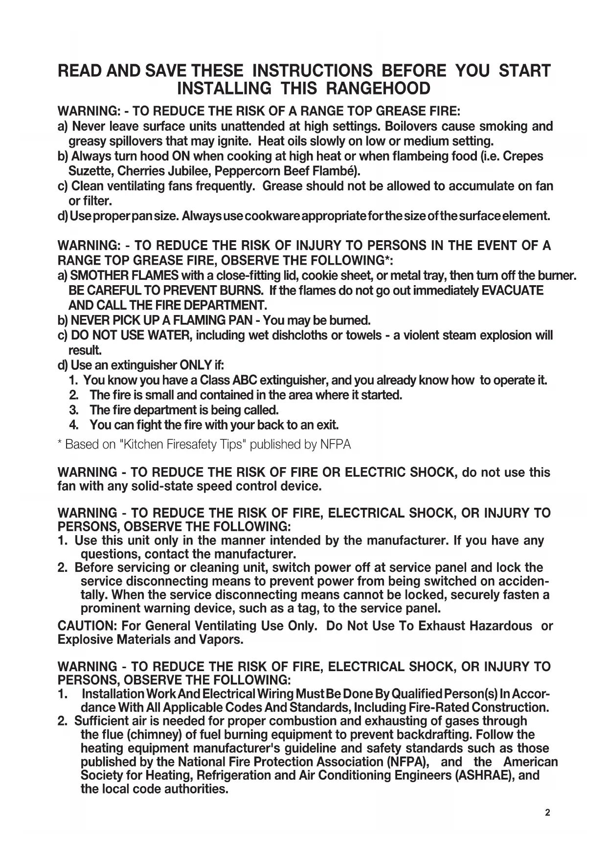
| Dimensions (W x D x H) | 48 inches (width); adjustable height: 34 5/16" - 46 1/8" (36" model) or 35 7/16" - 47 1/4" (48" model) |
| Weight | Approximately 40 lb |
| Power Supply | 120 V, 60 Hz, 15 A, dedicated circuit |
| Material | Stainless steel |
| Installation Type | Ceiling mount; 6" round metal duct required; external venting or recirculation with charcoal filter |
| Motor | Remote blower RB900/RB1200 or internal blower IB600/IB400/IB300 (optional) |
| Speeds | 4 speeds (1, 2, 3, Intensive) |
| Control | Touch with LED display; infrared remote control included (battery LR03-AAA not supplied) |
| Lighting | LED, dimmable (long press 2s) |
| Grease Filters | 4 dishwasher-safe metal filters (48" model); saturation detection (100h) |
| Charcoal Filter | Optional (FILTER1) for recirculation; lifespan 6 months; saturation alarm (200h) |
| Delay Function | Automatic shut-off after 30 minutes |
| Mounting Height | Minimum 35", recommended 60", max 72" above stove |
| Noise | Sound level not specified, estimated average |
| Warranty | 1 year parts and labor (manufacturing defects) |
| Certifications | UL listed, complies with NFPA |
Frequently Asked Questions - STRTIS48SSNB FABER
User questions about STRTIS48SSNB FABER
0 question about this device. Answer the ones you know or ask your own.
Ask a new question about this device
Download the instructions for your Basket in PDF format for free! Find your manual STRTIS48SSNB - FABER and take your electronic device back in hand. On this page are published all the documents necessary for the use of your device. STRTIS48SSNB by FABER.
USER MANUAL STRTIS48SSNB FABER
natural_image
Technical line drawing of a mechanical assembly with two rectangular components mounted on a base plate (no text or symbols)STRATUS NB
Installation Instructions Use and Care Information
READ AND SAVE THESE INSTRUCTIONS BEFORE YOU START INSTALLING THIS RANGEHOOD
WARNING: - TO REDUCE THE RISK OF A RANGE TOP GREASE FIRE:
a) Never leave surface units unattended at high settings. Boilovers cause smoking and greasy spillovers that may ignite. Heat oils slowly on low or medium setting.
b) Always turn hood ON when cooking at high heat or when flambeing food (i.e. Crepes Suzette, Cherries Jubilee, Peppercorn Beef Flambé).
c) Clean ventilating fans frequently. Grease should not be allowed to accumulate on fan or filter.
d) Use proper pan size. Always use cookware appropriate for the size of the surface element.
WARNING: - TO REDUCE THE RISK OF INJURY TO PERSONS IN THE EVENT OF A RANGE TOP GREASE FIRE, OBSERVE THE FOLLOWING*:
a) SMOTHER FLAMES with a close-fitting lid, cookie sheet, or metal tray, then turn off the burner. BE CAREFUL TO PREVENT BURNS. If the flames do not go out immediately EVACUATE AND CALL THE FIRE DEPARTMENT.
b) NEVER PICK UP A FLAMING PAN - You may be burned.
c) DO NOT USE WATER, including wet dishcloths or towels - a violent steam explosion will result.
d) Use an extinguisher ONLY if:
-
You know you have a Class ABC extinguisher, and you already know how to operate it.
-
The fire is small and contained in the area where it started.
-
The fire department is being called.
-
You can fight the fire with your back to an exit.
* Based on "Kitchen Firesafety Tips" published by NFPA
WARNING - TO REDUCE THE RISK OF FIRE OR ELECTRIC SHOCK, do not use this fan with any solid-state speed control device.
WARNING - TO REDUCE THE RISK OF FIRE, ELECTRICAL SHOCK, OR INJURY TO PERSONS, OBSERVE THE FOLLOWING:
- Use this unit only in the manner intended by the manufacturer. If you have any questions, contact the manufacturer.
- Before servicing or cleaning unit, switch power off at service panel and lock the service disconnecting means to prevent power from being switched on accidentally. When the service disconnecting means cannot be locked, securely fasten a prominent warning device, such as a tag, to the service panel.
CAUTION: For General Ventilating Use Only. Do Not Use To Exhaust Hazardous or Explosive Materials and Vapors.
WARNING - TO REDUCE THE RISK OF FIRE, ELECTRICAL SHOCK, OR INJURY TO PERSONS, OBSERVE THE FOLLOWING:
- Installation Work And Electrical Wiring Must Be Done By Qualified Person(s) In Accordance With All Applicable Codes And Standards, Including Fire-Rated Construction.
-
Sufficient air is needed for proper combustion and exhausting of gases through the flue (chimney) of fuel burning equipment to prevent backdrafting. Follow the heating equipment manufacturer's guideline and safety standards such as those published by the National Fire Protection Association (NFPA), and the American Society for Heating, Refrigeration and Air Conditioning Engineers (ASHRAE), and the local code authorities.
-
When cutting or drilling into wall or ceiling, do not damage electrical wiring and other hidden utilities.
- Ducted fans must always be vented to the outdoors.
ALL WALL AND FLOOR OPENINGS WHERE THE RANGEHOOD IS INSTALLED MUST BE SEALED.
This rangehood requires at least 35" of clearance between the bottom of the rangehood and the cooking surface or countertop. This hood has been approved by UL at this distance from the cooktop.
Consult the cooktop or range installation instructions given by the manufacturer before making any cutouts. MOBILE HOME INSTALLATION The installation of this rangehood must conform to the Manufactured Home Construction and Safety Standards, Title 24 CFR, Part 3280 (formerly Federal Standard for Mobile Home Construction and Safety, Title 24, HUD, Part 280).
VENTING REQUIREMENTS
Determine which venting method is best for your application. Ductwork can extend either through the wall or the roof.
The length of the ductwork and the number of elbows should be kept to a minimum to provide efficient performance. The size of the ductwork should be uniform. Do not install two elbows together. Use duct tape to seal all joints in the ductwork system. Use caulking to seal exterior walls and ceiling space opening around the cap.
Flexible ductwork is not recommended. Flexible ductwork creates back pressure and air turbulence that greatly reduces performance.
Make sure there is proper clearance within the walls and ceiling space for exhaust duct before making cutouts. Do not cut a joist or stud unless absolutely necessary. If a joist or stud must be cut, then a supporting frame must be constructed.
WARNING - To Reduce The Risk Of Fire, Use Only Metal Ductwork.
CAUTION - To reduce risk of fire and to properly exhaust air, be sure to duct air outside – Do not vent exhaust air into spaces within walls or ceilings or into attics, crawl spaces, or garages.
Cold Weather installations
An additional back draft damper should be installed to minimize backward cold air flow and a nonmetallic thermal break should be installed to minimize conduction of outside temperatures as part of the vent system. The damper should be on the cold air side of the thermal break. The break should be as close as possible to where the vent system enters the heated portion of the house.

WARNING
- Venting system MUST terminate outside the home.
- DO NOT terminate the ductwork in an attic or other enclosed space.
- DO NOT use 4" laundry-type wall caps.
- Flexible-type ductwork is not recommended.
- DO NOT obstruct the flow of combustion and ventilation air.
- Failure to follow venting requirements may result in a fire.
ELECTRICAL REQUIREMENTS
A 120 volt, 60 Hz AC-only electrical supply is required on a separate 15 amp fused circuit. A time-delay fuse or circuit breaker is recommended. The fuse must be sized per local codes in accordance with the electrical rating of this unit as specified on the serial/rating plate located inside the unit near the field wiring compartment.
ELECTRICAL INSTALLATION WITH WIRING BOX
THIS UNIT MUST BE CONNECTED WITH COPPER WIRE ONLY. Wire sizes must conform to the requirements of the National Electrical Code, ANSI/NFPA 70 - latest edition, and all local codes and ordinances. Wire size and connections must conform with the rating of the appliance. Copies of the standard listed above may be obtained from:
National Fire Protection Association
Batterymarch Park
Quincy, Massachusetts 02269
This appliance should be connected directly to the fused disconnect (or circuit breaker) through flexible, armored or nonmetallic sheathed copper cable. Allow some slack in the cable so the appliance can be moved if servicing is ever necessary. A UL Listed, 1/2" conduit connector must be provided at each end of the power supply cable (at the appliance and at the junction box).
When making the electrical connection, cut a 1 1/4" hole. A hole cut through wood must be sanded until smooth. A hole through metal must have a grommet.

WARNING
- Electrical ground is required on this rangehood.
- If cold water pipe is interrupted by plastic, nonmetallic gaskets or other materials, DO NOT use for grounding.
• DO NOT ground to a gas pipe. - DO NOT have a fuse in the neutral or grounding circuit. A fuse in the neutral or grounding circuit could result in electrical shock.
- Check with a qualified electrician if you are in doubt as to whether the rangehood is properly grounded.
- Failure to follow electrical requirements may result in a fire.
State of California Proposition 65 Warning (US only)
WARNING
This product contains chemicals known to the State of California to cause cancer and birth defects or other reproductive harm.
For more information go to www.P65Warnings.ca.gov
RANGEHOOD DIMENSIONS
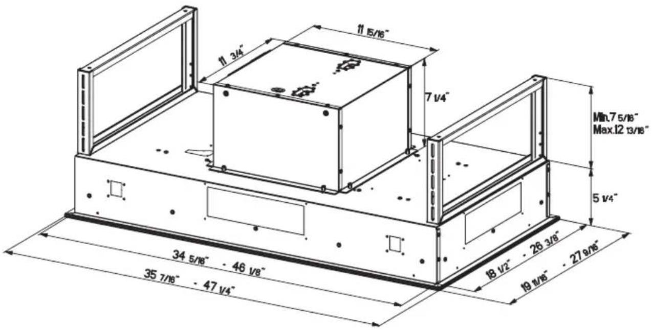
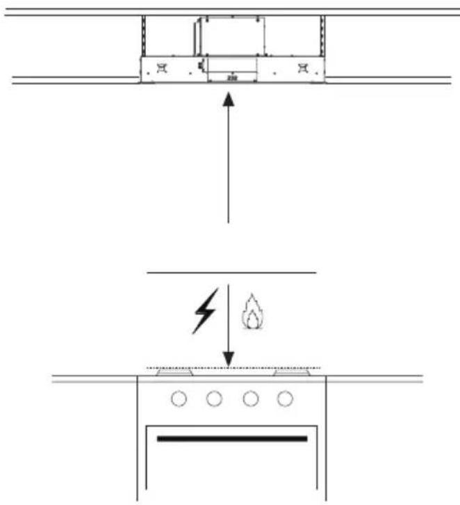
Recommended 60" mounting height above the cooking surface for best performance, but can be mounted up to 72" maximum away the cooking surface.
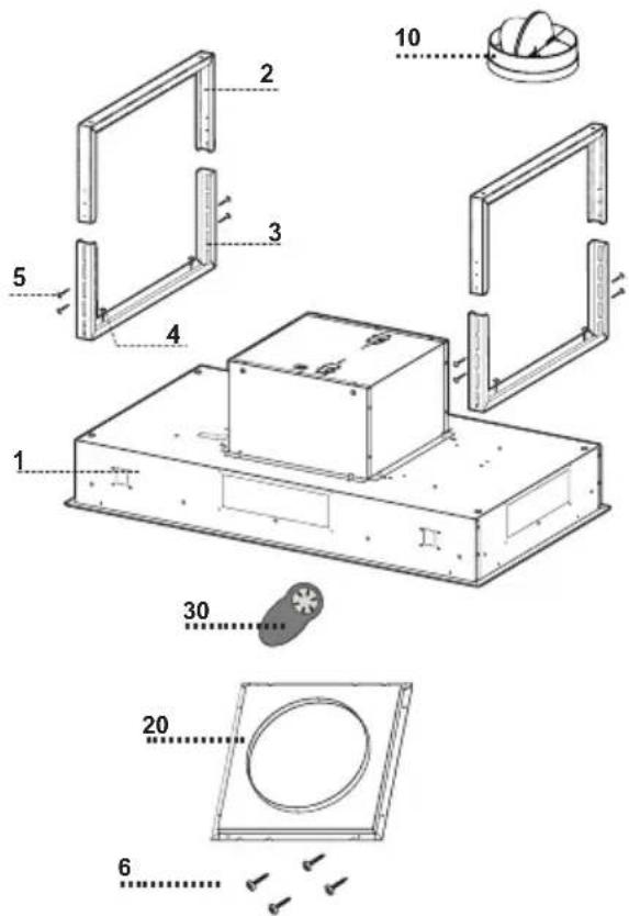
MAIN PARTS
Components
Ref. Qty. Product Components
1 1 Hood Body, complete with: Controls, Lights, Filters.
2 2 Upper fixing Hood Brackets
3 2 Bottom fixing Hood Brackets
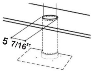
10 1 Damper ø 5 7/8"
20 1 Flange 10"(Not Included)
30 1 Remote Control
Ref. Qty. Installation Components
4 4 Screws 1/4" x 9/16"
5 8 Screws 1/8" x 3/8"
6 4 Screws 1/8" x 1/4"
Qty. Documentation
1 Instruction Manual
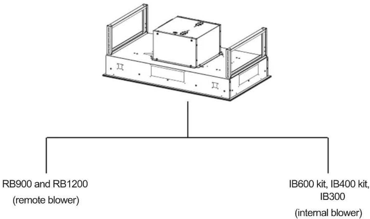
"CAUTION - To Reduce The Risk Of Fire And Electric Shock, Install This Rangehood Only With Remote Blower Models RB900 or RB1200 Manufactured by Faber Or Integral Blowers Manufactured by Faber, Model(s) IB600 kit, IB400 kit, IB300 or generic remote blower rated max 2,7A suitable for use with solid state speed control.
Parts needed
- 6" Round Metal ductwork
Available Accessories
Activated Charcoal Filter Accessory - sku#; FILTER 1
Internal 600 PRO Blower sku#; IB600 kit
Internal 400 Blower sku#; IB400 kit
Internal 300 Blower sku#; IB300
Remote Blower 900 sku#; RB900
Remote Blower 1200 sku#; RB1200
10" Flange for Remote Blower sku# FLANGE10
INSTALLATION
COMBINATIONS HOODS AND MOTOR KITS
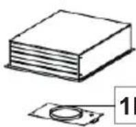
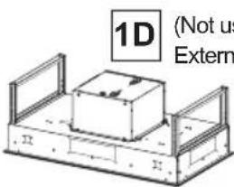
1B (Not needed with Stratus)
Choose your ducting method
Non Ducted - Recirculation OptionDucted Ve
Activated Charcoal Filter Accessory FILTER1 required (Purchased separately). Register cover for air duct exit is shown for design - not included.
natural_image
Diagram of a mechanical or fluid system with directional arrows and layered components (no text or symbols)When used in recirculation mode, To Reduce the Risk of Fire and Shock use only conversion kit Model FILTER1
Blower Cable Wiring Box & Power Supply Cable Wiring Box
natural_image
Diagram of a mechanical device with internal compartments and a hand gesture indicating motion (no text or symbols)
natural_image
Diagram of a mechanical assembly with hands and arrows indicating motion (no text or symbols)WIRING BOX 1 for
connecting the Home
power supply cable
with the Hood.
natural_image
Technical diagram of a device rear panel with internal components and directional arrows indicating movement (no text or symbols)WIRING BOX 2
for connecting the
External Blower with
the Hood.
Ceiling Hood Install Preparation
1 Do not make any cutouts until you have decided whether this installation will be ducted or non-duct and then plan accordingly.
natural_image
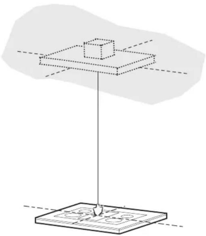
Pure diagram of a 3D mechanical assembly with no text, numbers, or symbols! WARNING DUE TO THE SIZE AND WEIGHT OF THIS RANGE-HOOD, THE SUPPORT MUST BE FIRMLY ATTACHED TO THE CEILING. For plaster or sheet rock ceiling, the support must be attached to the joists. If this is not possible, a support structure must be built behind the plaster or sheet rock. The manufacturer assumes no responsibility for injury or damage caused by improper installations.
Put a thick, protective covering over cooktop to protect from damage or dirt.
Determine and clearly mark with a pencil on the ceiling where the rangehood will be installed.
Determine and make necessary cuts for the ductwork. The duct opening is shown on the mounting template.
Install ductwork before mounting the hood.
Determine the proper location for the Power Supply Cable as indicated on the template.
Use a 1 1/4" Drill Bit to make this hole. Run the Power Supply Cable. Use caulking to seal around the hole.
A knockout for threading through the Power Supply from the ceiling is located on the top of the frame. Do not connect the Power Cable to the Wiring Box or power up the hood at this time. Run enough power cable from the ceiling to reach the wiring box on the hood.
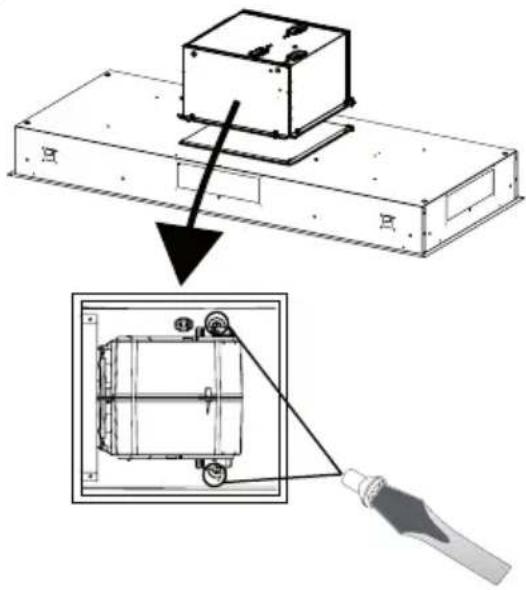
External Blower Installation 10"
If you use the remote blower kit, RB900 or RB1200, please throw away the flange (1B) given with the remote blower kit, shown on page 7.
2
natural_image
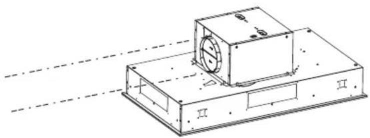
Technical line drawing of an electronic device with internal components and wiring (no text or symbols)Unfasten the 4 screws to dismount the Blower Box from the hood body and to save screws.
The Blower Box is not used for Remote Blower installation and can be discarded or saved for future use if converted to Internal Blower.
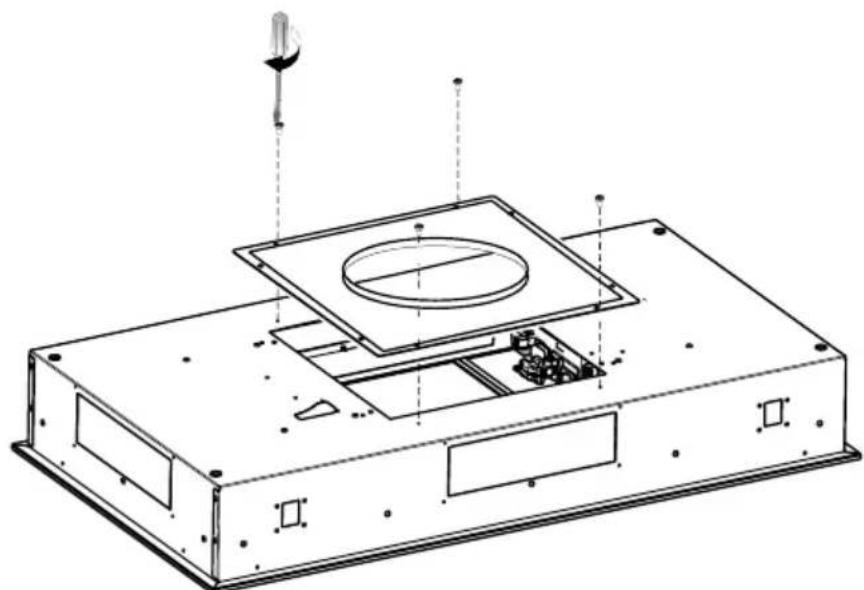
3
Fix the 10"
flange(#FLANGE10
-purchased separately) with the 4 screws provided in the hardware bag as shown.
natural_image
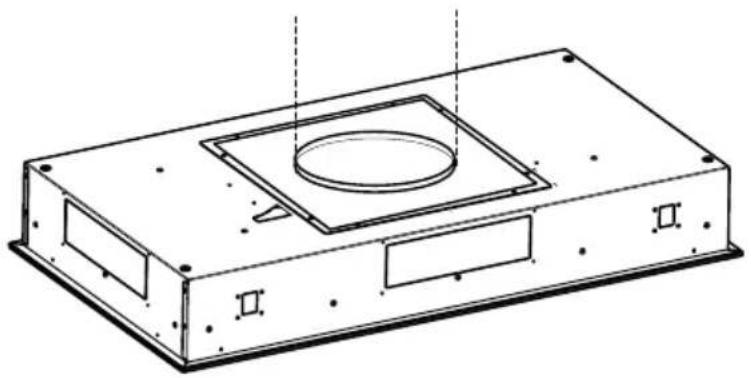
Technical line drawing of an electronic device casing with internal components and a sensor or probe inserted (no text or symbols)4
Connect the Hood body air outlet with the Remote Blower air outlet.
natural_image
Technical line drawing of a rectangular electronic device casing with a central square recess and two labeled sections (II and II), no text or symbols present.5
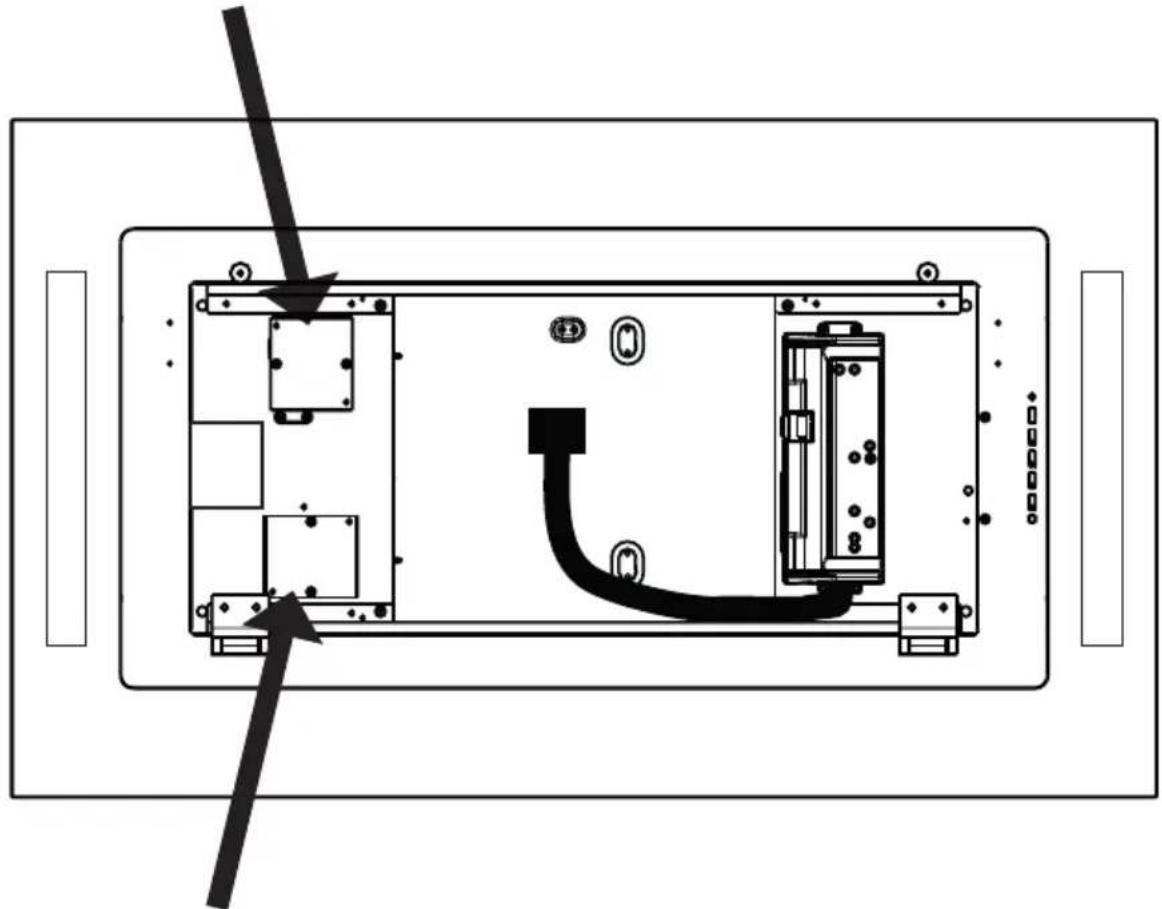
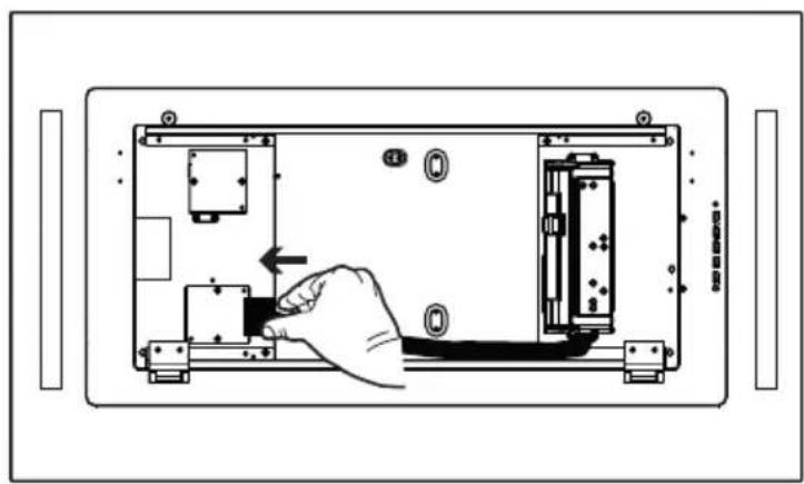
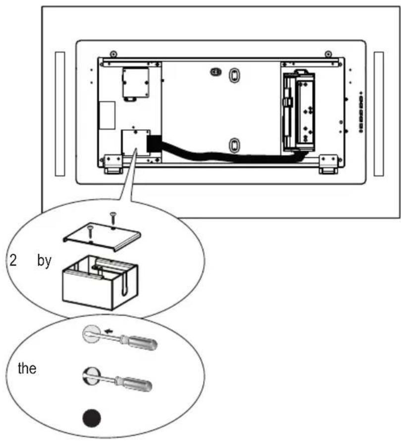
From Inside the Hood connect the Cable to the Wiring BOX as shown in the image to the right.
From Inside the Hood, remove the Cover from the wiring box 2 removing two screws.
Break the correct hole in the Wiring Box for passing the cables from the remote blower.
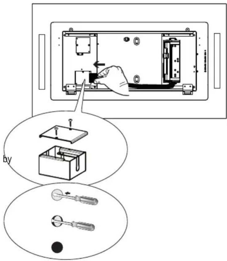
Connect the cable from the Remote Blower with the two wires inside the Wiring Box by twist-on type wire connector and matching the color
Replace the field wiring compartment cover.
Check the Wiring Diagram.
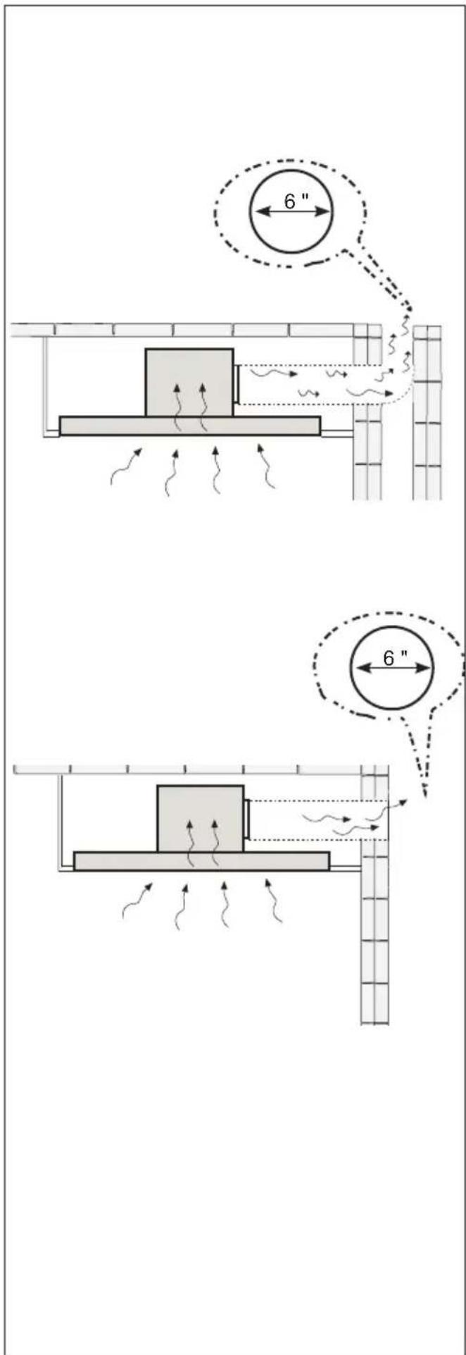
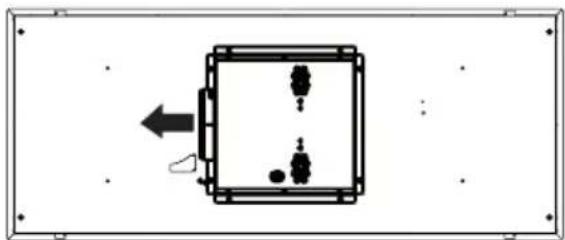
External Blower Installation 6"
If you use the remote blower kit, RB900 or RB1200, please throw away the flange (1B) given with the remote blower kit1 shown on page 7. With this installation there may be a performance degradation due to the transition from 6" to 10" of the Remote Blowers.
1
natural_image
Simple diagram of a rectangular device with internal components and an arrow indicating direction (no text or symbols)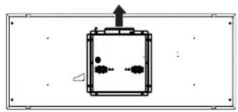
natural_image
Simple line drawing of a rectangular device with internal components and an upward arrow, no text or symbols present.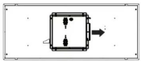
natural_image
Simple diagram of a rectangular device with internal components and an arrow indicating direction (no text or symbols)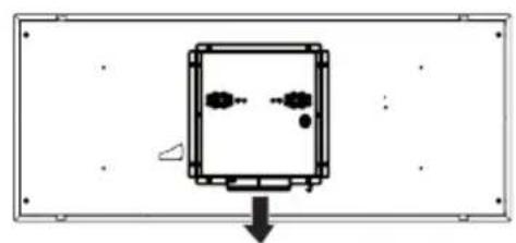
natural_image
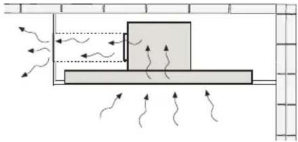
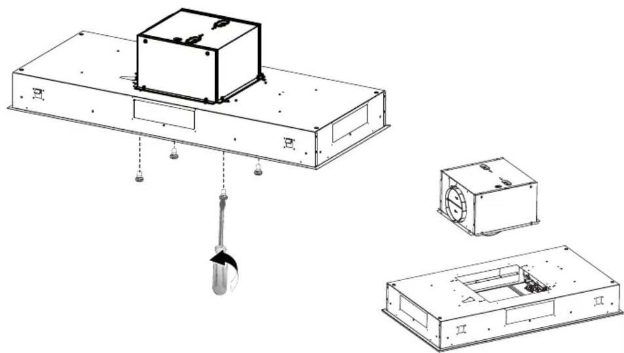
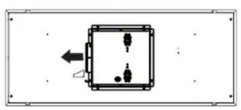
Pure diagram of a rectangular frame with internal components and a downward arrow, no text or symbols present.The Blower Box can be positioned in four different venting directions as shown. Choose the correct position for your installation.
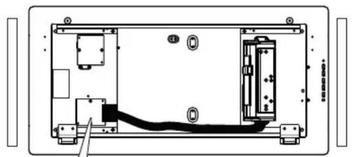
If necessary the Blower Box is dismounted from the body as shown in the image to the right.
natural_image
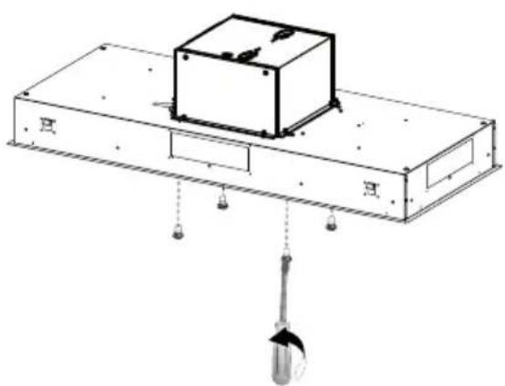
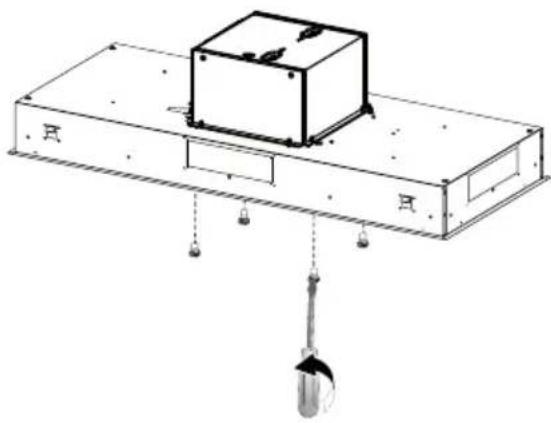
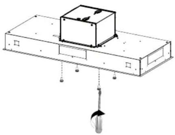
Technical line drawing of a mechanical assembly with a central box and hanging weights (no text or symbols)2
Connect the ducting from the Remote Blower to the Blower Box. Use clamps to secure (purchased separately).
natural_image
Technical line drawing of a mechanical device with a central fan and rectangular base (no text or symbols)3
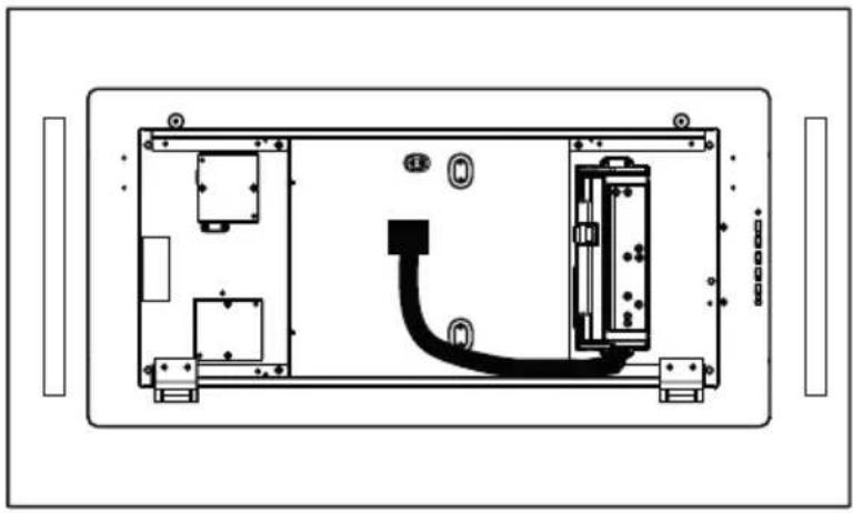
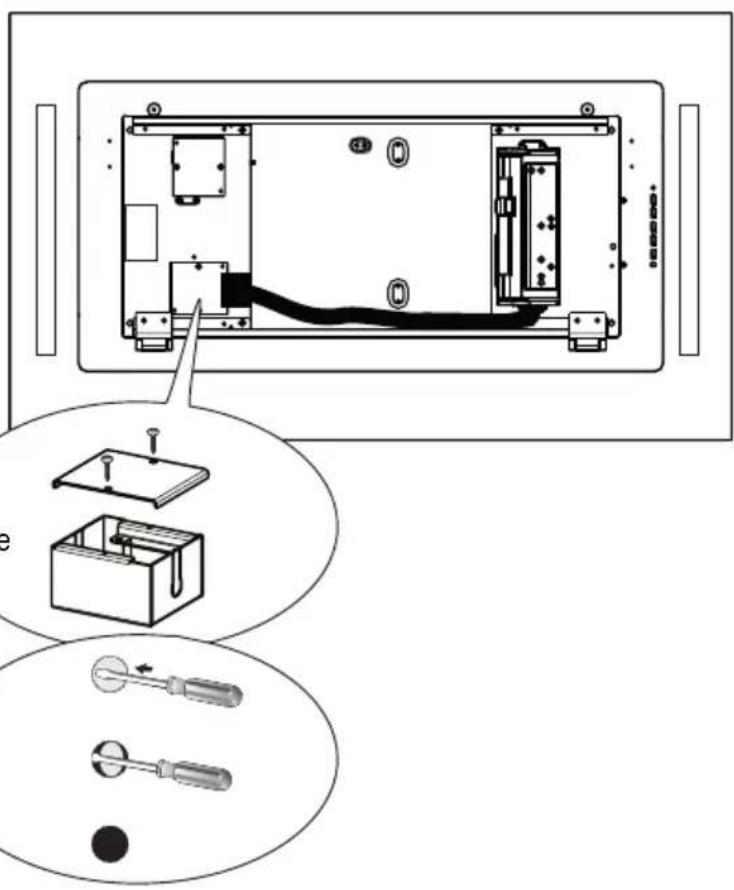
From Inside the Hood connect the cable to the Wiring BOX2.
From inside the hood, remove the cover from the Wiring Box removing the two screws.
Break the hole in the Wiring Box for passing the cables from remote blower.
Connect the cable from the Remote Blower with the two wire inside the Wiring Box by twist-on type wire connector and matching the color.
Replace the field wiring compartment cover.
Check the Wiring Diagram.

Internal Blower Installation
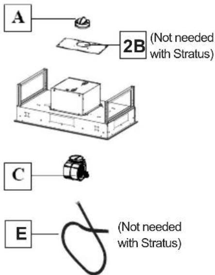
If you use the internal blower kit, IB600 kit or IB400 kit or IB300, please throw away the damper (A), the flange (2B) and the cable (E), given with the internal blower kit, shown on page 7.
2
natural_image
Technical line drawing of a mechanical assembly with a central box and hanging weights (no text or symbols)Unfasten the 4 screws to dismount the Box for the blower.
3
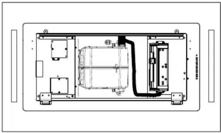
Position Internal Blower as shown into the removed Blower Box. Secure the Internal Blower in the Blower Box with the two screws provided with the Internal Blower.
4
natural_image
Simple diagram of a square enclosure with internal compartments and directional arrows, no text or symbols present.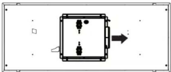
natural_image
Simple diagram of a rectangular device with internal components and an arrow indicating direction (no text or symbols)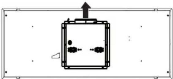
natural_image
Simple line drawing of a rectangular chamber with internal components and an upward arrow, no text or symbols present.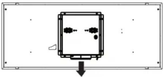
natural_image
Simple line drawing of a mechanical component with arrows indicating direction (no text or symbols)The blower can be positioned in four different venting directions as shown.
5
Connect the cable to the Motor.
natural_image
Technical line drawing of a device enclosure with internal components and wiring (no text or symbols)After the Blower is mounted in the hood plug the Connector into the Blower
natural_image
Technical line drawing of a mechanical or electrical enclosure with internal components and mounting brackets (no text or symbols)6

natural_image
Technical line drawing of a mechanical assembly with a central box and hanging weights (no text or symbols)Fix the Box with the Blower with the same 4 screws removed previously.
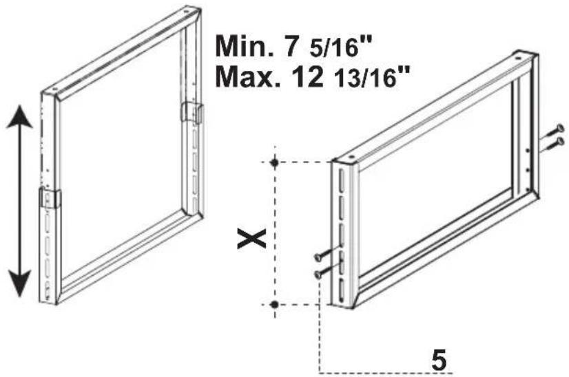
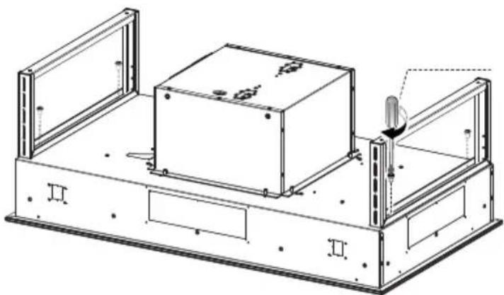
Assemble the Brackets
7
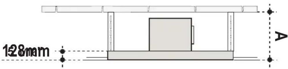
X = A - 5 1/16"
As shown, you have to accommodate for the height of the hood body into your space overhead. After determining bracket height use the #5 Screws from Component Page 6 to assemble brackets.
HOOD INSTALLATION BEFORE THE SOFFIT IS COMPLETED
8.a
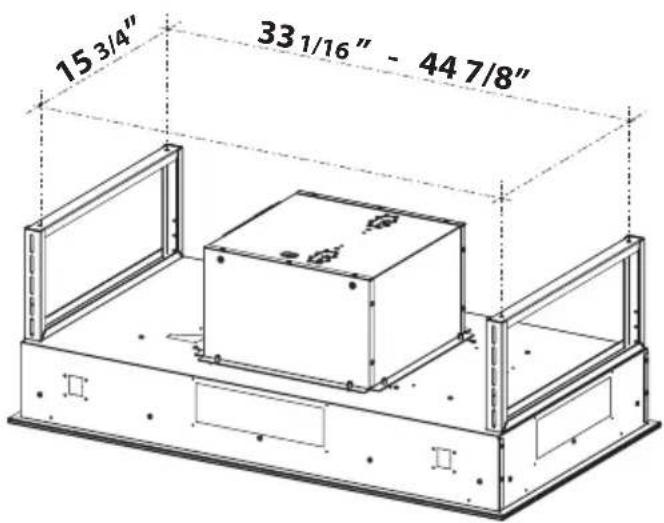
Ceiling Bracket Installation
See below for a detailed image on drilling the holes onto the fastening surface (inside ceiling or soffit) that will then be used to mount the bracket fixtures. The fasteners used must be compatible with the 5/16" hole and are purchased separately.
| Hood | ||
| 36" | 15 3/4" | 33 1/16" |
| 48" 15 | 3/4" 44 7/8" |
9.a
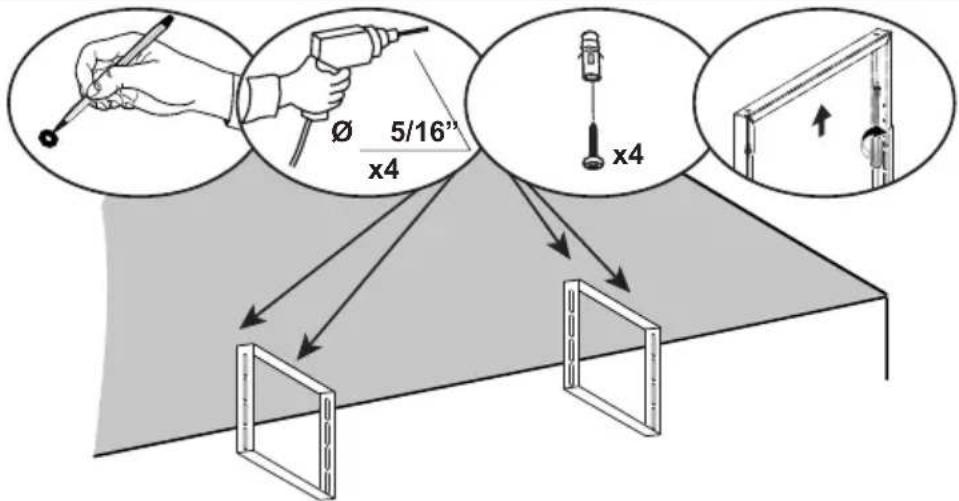
Use the brackets to mark your holes for location of the ceiling fasteners(purchased separately).
Use wall plugs or other securing hardware in conjunction with the ceiling fasteners (purchased separately).
natural_image
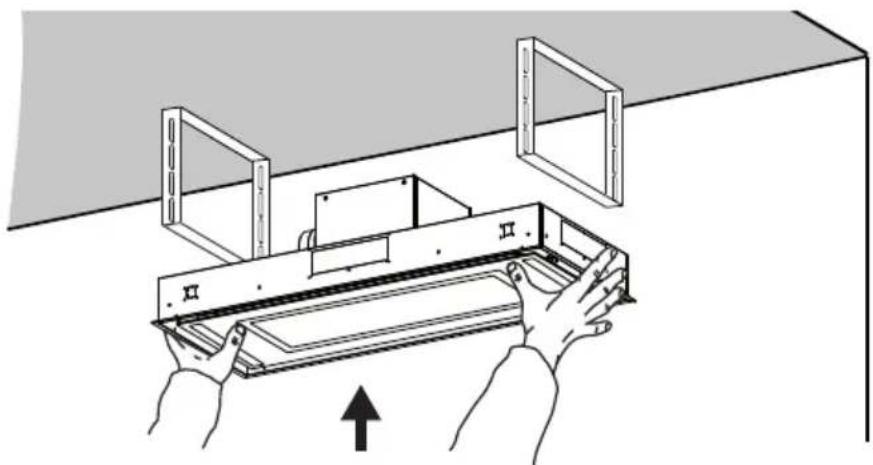
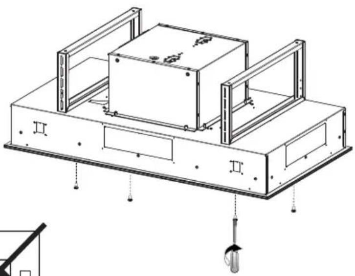
Illustration of hands installing or adjusting a mechanical component with a wall-mounted frame (no text or symbols)10.a
Use the #4 Screws from the
Component list on Page 6 to attach the hood body to the hood ceiling brackets.
Access is needed in the space above.
natural_image
Technical line drawing of a mechanical assembly with two rectangular components and mounting brackets (no text or symbols)HOOD INSTALLATION AFTER THE SOFFIT IS COMPLETED
8.b
Ceiling Cutout for Soffit
See image with dimensions for ceiling cutout.
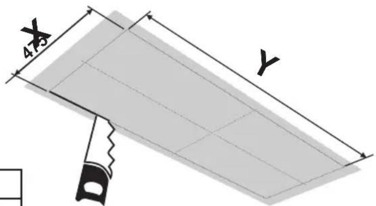
| Hood X | Y | |
| 36" | 18 11/16" | 34 9/16" |
| 48" | 26 9/16" | 46 3/8" |
Ceiling Bracket Installation for Soffit
9.b
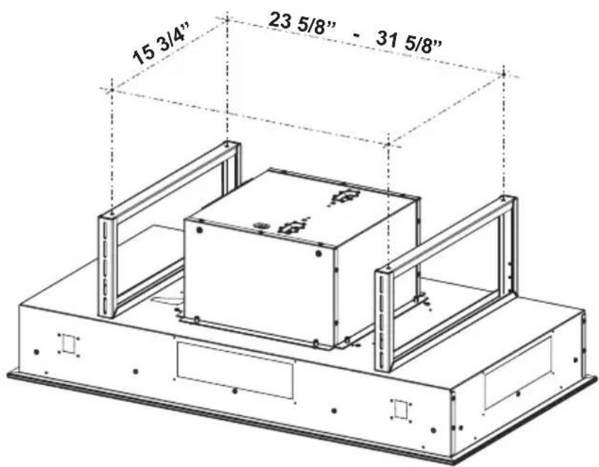
| Hood | ||
| 36" 15 3/4" 23 5/8" | ||
| 48" 15 3/4" 31 5/8" | ||
See below for a detailed image on drilling the holes onto the fastening surface (inside ceiling or soffit) that will then be used to mount the bracket fixtures. The fasteners used must be compatible with the 5/16" hole and are purchased separately.
10.b
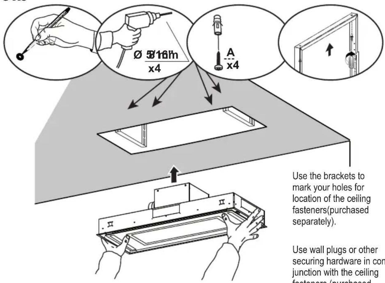
Use the brackets to mark your holes for location of the ceiling fasteners(purchased separately).
Use wall plugs or other securing hardware in conjunction with the ceiling fasteners (purchased separately).
Use the #4 Screws from the Component list on Page 6 to attach the hood ceiling brackets from the bottom.
natural_image
Technical line drawing of a mechanical assembly with mounting brackets and structural supports (no text or symbols)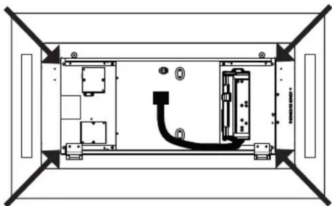
natural_image
Top-down schematic of a rectangular device with internal components and labeled ports (no text or symbols)
Install the hood with the control panel on the right as shown above.
Ducted Venting Installation
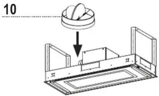
Install Damper that is included with the Hood before connecting to the ductwork.
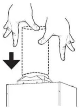
natural_image
Illustration of two hands performing a physical maneuver with a curved object underneath (no text or symbols)Connect the hood to the pipe for air outlet. Use duct tape to seal the joint.
Non Ducted - Recirculation Option
See the image above and below as two duct venting options for non-ducted recirculation back into the room.
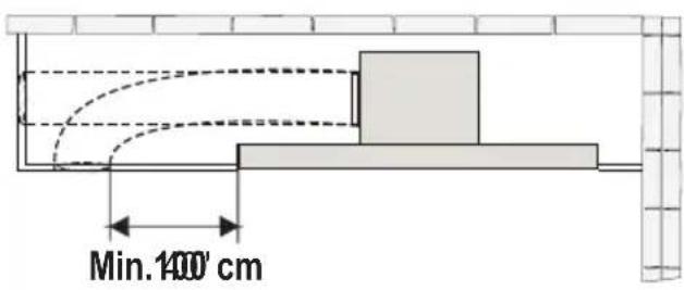
keep the return air duct at least 40" away from the side of the Stratus
12 13
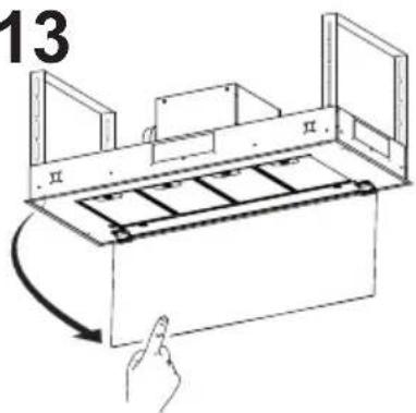
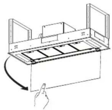
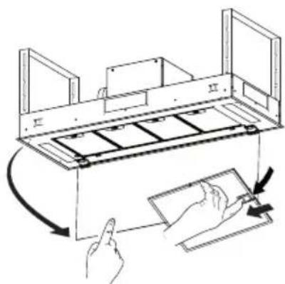
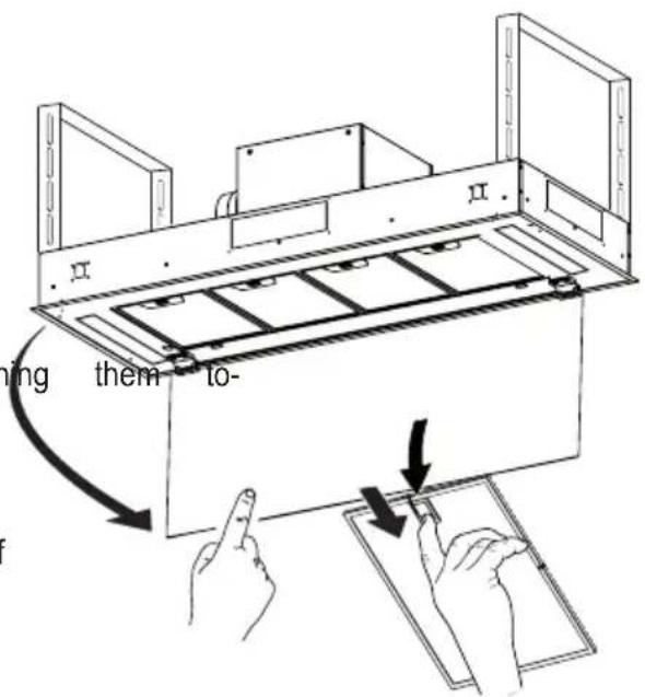
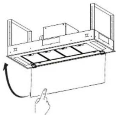
Open the filter cover panel. The filter cover panel is held by a magnet catch, pull down with enough force to release as shown above.
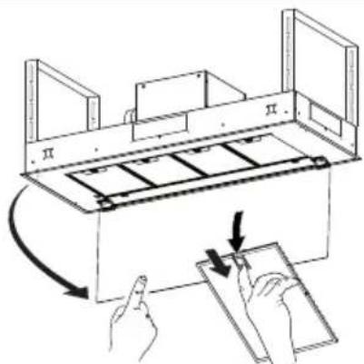
Remove the grease filters one at a time, pushing them towards the back of the unit, and at the same time pulling downward and set aside.
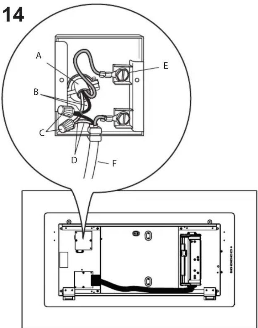
Installation of wiring box connection 1
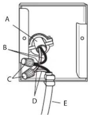
Remove the cover from the field wiring compartment. DO NOT turn on the power until installation is complete! Connect the Power Supply Cable to the rangehood. Connect the Green (Green and Yellow) ground wire under the Green grounding screw. Attach the White lead of the power supply to the White lead of the rangehood with a twist-on type wire connector. Attach the Black lead of the power supply to the Black lead of the rangehood with a twist-on type wire connector.
Replace the field wiring compartment cover and the grease filters.
Check the Wiring Diagram.
A. Home power supply cable
B. Black wires
C. UL listed wire connectors
D. White wires
E. Green (or bare) ground wire from home power supply to be connected to green ground screw
F. Range hood power supply cable
15
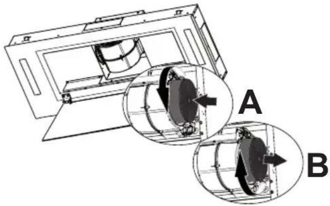
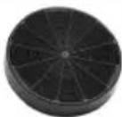
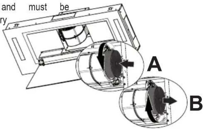
For Non-Ducted Recirculation Option
natural_image
Technical diagram of a mechanical device with two circular insets labeled A and B showing internal components (no text or symbols present)Attach each charcoal filter to the black grid on each side of the blower. Press the charcoal filter tightly to the black grid on the blower side and rotate the filter clockwise (towards the front of the insert hood) until it locks into place (A). Turn counterclockwise (towards the back of the insert hood) to remove (B).
Required Activated Charcoal Filter Accessory - sku # - FILTER1 (purchased separately)
natural_image
Diagram of a hand inserting a card into a device (no text or symbols present)1716

natural_image
Diagram of a hand pressing a button into a rack with a curved arrow indicating rotation (no text or symbols)Close the filter cover panel. Replace the grease fil
USE AND CARE INFORMATION
For Best Results
Start the rangehood several minutes before cooking to develop proper airflow. Allow the rangehood to operate for several minutes after cooking is complete to clear all smoke and odors from the kitchen.
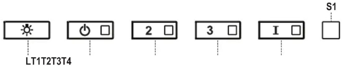
| Button | Function Led | |
| L Turns the lights on/off at maximum strength. - | ||
| Press and hold the button for approximately 2 seconds to turn the Dimmer Lights On/Off. | - | |
| T1 Turns the motor on/off at speed one. ON | ||
| T2 Turns the Motor on at speed two. ON | ||
| T3 Turns the Motor on at speed three. ON | ||
| T4 Turns the Motor on at INTENSIVE Speed.This speed is timed to run for 6 minutes. At the end of this time, the system returns automatically to the speed that was set before. If it is activated with the motor turned off, the hood will switch to OFF at the end of the time. | ON | |
| S1 Signals the Metal Grease Filter saturation alarm, indicating that it is necessary to wash the filters. The alarm is triggered after the Hood has been in operation for 100 working hours. (Refer to Page 18 for Cleaning Filters and Reset of Filter Alarm) | ON | |
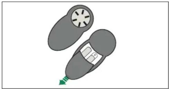
REMOTE CONTROL
The appliance can be controlled using a remote control powered by a 1.5 V carbon-zinc alkaline batteries of the standard LR03-AAA type (not included).
- Do not place the remote control near to heat sources.
• Used batteries must be disposed of in the proper manner.
natural_image
Diagram of a car with a circular vent and a green arrow indicating motion (no text or symbols)
natural_image
Black handheld remote control device with five rotary buttons (no text or symbols visible)| Motor Motor On / Off | |
| - | |
| + | |
| i | Intensive Activates/Deactivates the Intensive function |
| ∅ | Delay Activates/Deactivates the Delay function |
| Light | |
Cleaning metal grease filters
These can be washed in the dishwasher, and need to be cleaned whenever the S1 Led comes on or at least once every 2 months of use, or more frequently if use is particularly intensive.
Resetting the Grease Filter Alarm
• Turn the Lights and the Hood off.
- Press T3 and hold for at least 3 seconds, until LED flashes three times in confirmation.
Cleaning the Filters
- Open the Panel.
- Remove the Filters one at a time, pushing wards the back of the unit and at the same time pulling downward.
- Wash the Filters without bending them, and leave them to dry completely before replacing. (If the surface of the filter changes color as time goes by, this will have absolutely no effect on the efficiency of the filter itself.)
- Replace the grease filters, taking care to ensure that the handle faces forward
- Close the Panel.
• 4 Filters - 48" model, 3 Filters - 36" model.
Replacing Activated Charcoal Filter
They cannot be washed or regenerated, a changed when led S1 starts to flash, or at least once every 6 months. The Alarm signal, if it has been activated, only appears when the Hood Blower is turned on.
Resetting the alarm signal
• Turn the Lights and the Hood Blower off.
- Press T3 and hold for at least 3 seconds, until LED flashes three times in confirmation.
Cleaning the Filters
- Open the Panel.
- Remove the Metal Grease Filter.
- Remove the saturated Activated Charcoal Filters, as indicated (A).
• Fit the new Filters, as indicated (B). - Replace the Metal grease filters.
- Close the Panel.
Lighting unit
• LED lights must be replaced by Faber factory authorized service.
Wiring Diagram
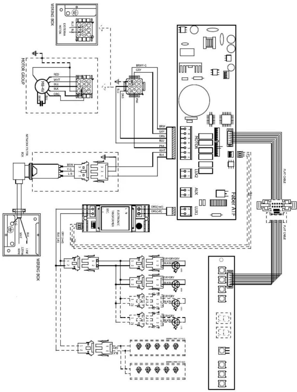
flowchart
graph TD
    A["Motor Group"] --> B["ML8-4V"]
    B --> C["BLK 12"]
    B --> D["BLK 13"]
    B --> E["BLK 14"]
    B --> F["BLK 15"]
    B --> G["BLK 16"]
    B --> H["BLK 17"]
    B --> I["BLK 18"]
    B --> J["BLK 19"]
    B --> K["BLK 20"]
    B --> L["BLK 21"]
    B --> M["BLK 22"]
    B --> N["BLK 23"]
    B --> O["BLK 24"]
    B --> P["BLK 25"]
    B --> Q["BLK 26"]
    B --> R["BLK 27"]
    B --> S["BLK 28"]
    B --> T["BLK 29"]
    B --> U["BLK 30"]
    B --> V["BLK 31"]
    B --> W["BLK 32"]
    B --> X["BLK 33"]
    B --> Y["BLK 34"]
    B --> Z["BLK 35"]
    B --> AA["BLK 36"]
    B --> AB["BLK 37"]
    B --> AC["BLK 38"]
    B --> AD["BLK 39"]
    B --> AE["BLK 40"]
    B --> AF["BLK 41"]
    B --> AG["BLK 42"]
    B --> AH["BLK 43"]
    B --> AI["BLK 44"]
    B --> AJ["BLK 45"]
    B --> AK["BLK 46"]
    B --> AL["BLK 47"]
    B --> AM["BLK 48"]
    B --> AN["BLK 49"]
    B --> AO["BLK 50"]
    B --> AP["BLK 51"]
    B --> AQ["BLK 52"]
    B --> AR["BLK 53"]
    B --> AS["BLK 54"]
    B --> AT["BLK 55"]
    B --> AU["BLK 56"]
    B --> AV["BLK 57"]
    B --> AW["BLK 58"]
    B --> AX["BLK 59"]
    B --> AY["BLK 60"]
    B --> AZ["BLK 61"]
    B --> BA["BLK 62"]
    B --> BB["BLK 63"]
    B --> BC["BLK 64"]
    B --> BD["BLK 65"]
    B --> BE["BLK 66"]
    B --> BF["BLK 67"]
    B --> BG["BLK 68"]
    B --> BH["BLK 69"]
    B --> BI["BLK 70"]
    B --> BJ["BLK 71"]
    B --> BK["BLK 72"]
    B --> BL["BLK 73"]
    B --> BM["BLK 74"]
    B --> BN["BLK 75"]
    B --> BO["BLK 76"]
    B --> BP["BLK 77"]
    B --> BQ["BLK 78"]
    B --> BR["BLK 79"]
    B --> BS["BLK 80"]
    B --> BT["BLK 81"]
    B --> BU["BLK 82"]
    B --> BV["BLK 83"]
    B --> BW["BLK 84"]
    B --> BX["BLK 85"]
    B --> BY["BLK 86"]
    B --> CA["BLK 87"]
    B --> CB["BLK 88"]
    B --> CC["BLK 89"]
    B --> CD["BLK 90"]
    B --> CE["BLK 91"]
    B --> CF["BLK 92"]
    B --> CG["BLK 93"]
    B --> CH["BLK 94"]
    B --> CI["BLK 95"]
    B --> CJ["BLK 96"]
    B --> CK["BLK 97"]
    B --> CL["BLK 98"]
    B --> CM["BLK 99"]
    B --> CN["BLK 100"]
FABER
FABER CONSUMER WARRANTY & SERVICE
All Faber products are warranted against any defect in materials or workmanship for the original purchaser for a period of 1 year from the date of original purchase (requires proof of purchase). This warranty covers labor and replacement parts. Faber, at its option, may repair or replace the product or components necessary to restore the product to good working condition. To obtain warranty service, contact the dealer from whom you purchased the range hood, or the local Faber distributor. If you cannot identify a local Faber distributor, contact us at (508) 358-5353 for the name of a distributor in your area.
The following is not covered by Faber's warranty:
- Service calls to correct the installation of your range hood, to instruct you how to use your range hood, to replace or repair house fuses or to correct house wiring or plumbing.
- Service calls to repair or replace range hood light bulbs, fuses or filters. Those consumable parts are excluded from warranty coverage.
- Repairs when your range hood is used for other than normal, single-family household use.
- Damage resulting from accident, alteration, misuse, abuse, fire, flood, acts of God, improper installation, installation not in accordance with electrical or plumbing codes or Faber documentation, or use of products not approved by Faber.
- Replacement parts or repair labor costs for units operated outside the United States or Canada, including any non-UL or C-UL approved Faber range hoods.
- Repairs to the hood resulting from unauthorized modifications made to the range hood.
- Expenses for travel and transportation for product service in remote locations and pickup and delivery charges. Faber range hoods should be serviced in the home.
THIS WARRANTY DOES NOT ALLOW RECOVERY OF INCIDENTAL OR CONSEQUENTIAL DAMAGES, INCLUDING, WITHOUT LIMITATION, DIRECT, INDIRECT, INCIDENTAL, SPECIAL OR CONSEQUENTIAL DAMAGES, PERSONAL INJURY/WRONGFUL DEATH OR LOST PROFITS FABER WARRANTY IS LIMITED TO THE ABOVE CONDITIONS AND TO THE WARRANTY PERIOD SPECIFIED HEREIN AND IS EXCLUSIVE. EXCEPT AS EXPRESSLY SPECIFIED IN THIS AGREEMENT, FABER DISCLAIMS ALL EXPRESS OR IMPLIED CONDITIONS, REPRESENTATIONS, AND WARRANTIES INCLUDING, WITHOUT LIMITATION, ANY IMPLIED WARRANTIES OF MERCHANTABILITY OR FITNESS FOR A PARTICULAR PURPOSE.
This warranty gives you specific legal rights that may vary from state to state.
Model#:
Serial #: ____
January 4, 2016
VEUILLEZ LIRE ET CONSERVER LA PRÉSENTE NOTICE AVANT DE COMMENCER L'INSTALLATION DE LA HOTTE DE CUISINE
AVERTISSEMENT : - POUR RÉDUIRE LE RISQUE D'UN FEU DE GRAISSE SUR LA TABLE DE CUISSON :
National Fire Protection Association
Batterymarch Park
natural_image
Simple line drawing of stacked documents and a separate circular component labeled '1B' (no text or symbols on the main diagram)natural_image
Diagram of a mechanical or fluidic system with directional arrows and layered components (no text or symbols)natural_image
Diagram of a mechanical assembly with a hand pointing to a component, showing internal structure and rotation arrow (no text or symbols)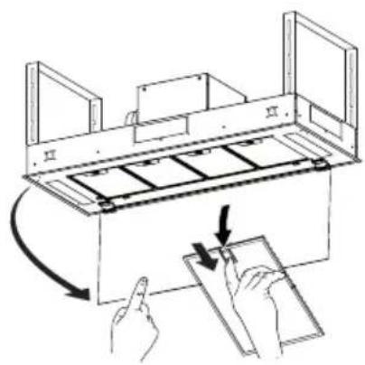
natural_image
Diagram of a mechanical assembly with hands and arrows indicating motion (no text or symbols)natural_image
Technical diagram of a device rear panel with internal components and directional arrows indicating movement (no text or labels)BOÎTIER DE
CONNEXION (WIRING
BOX 2)
pour le branchement
natural_image
Pure diagram of a 3D object with dashed lines and a vertical line, no text or symbols present
AVERTISSEMENT
natural_image
Technical line drawing of an electronic device with labeled components (no text or symbols present)natural_image
Technical line drawing of an electronic device casing with internal components and a sensor or probe inserted (no text or symbols)4
natural_image
Technical line drawing of a rectangular electronic device casing with a central square recess and two labeled sections (II and II), no text or symbols present.5

natural_image
Simple diagram of a square enclosure with internal components and directional arrows, no text or symbols present.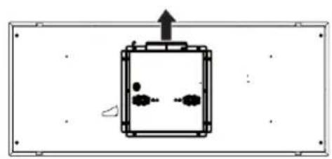
natural_image
Simple line drawing of a rectangular device with internal components and an upward arrow, no text or symbols present.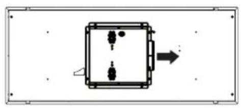
natural_image
Simple diagram of a rectangular box with internal components and an arrow pointing right (no text or symbols)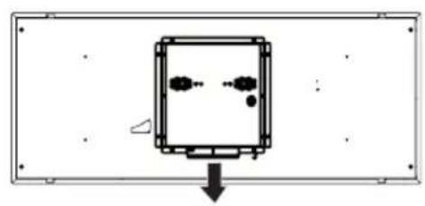
natural_image
Simple diagram of a rectangular device with internal components and an arrow pointing downward (no text or symbols)natural_image
Technical line drawing of a mechanical assembly with a central box and hanging component (no text or symbols)2
natural_image
Technical line drawing of a mechanical device with a central circular component and rectangular base (no text or symbols)3
natural_image
Technical line drawing of a mechanical assembly with a central box and hanging weights (no text or symbols)natural_image
Simple diagram of a rectangular chamber with internal components and an arrow indicating direction (no text or symbols)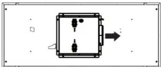
natural_image
Simple diagram of a rectangular device with internal components and an arrow pointing to it (no text or symbols)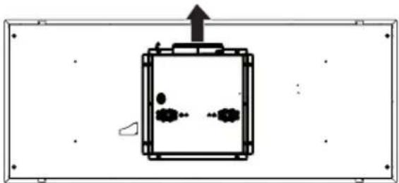
natural_image
Simple line drawing of a rectangular device with internal components and an upward arrow, no text or symbols present.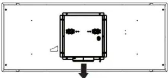
natural_image
Simple diagram of a device with internal components and an arrow pointing downward (no text or symbols)natural_image
Technical line drawing of a device enclosure with internal components and wiring (no text or symbols)natural_image
Technical line drawing of a mechanical or electrical enclosure with internal components and mounting brackets (no text or symbols)5
natural_image
Technical line drawing of a mechanical assembly with a central box and hanging weights (no text or symbols)natural_image
Illustration of hands installing or adjusting a mechanical component with a wall-mounted frame (no text or symbols)10.a
natural_image
Technical line drawing of a mechanical assembly with two rectangular components and mounting brackets (no text or symbols)| Hotte | ||
| 36" 15 3/4" 23 5/8" | ||
| 48" 15 3/4" 31 5/8" | ||
natural_image
Top-down schematic of a rectangular room with internal compartments and a central control unit (no text or symbols)
natural_image
Illustration of two hands performing a physical maneuver with a curved object underneath (no text or symbols)filtre. Le
natural_image
Technical diagram of a mechanical device with two circular insets labeled A and B showing internal components (no text or symbols present)1716
natural_image
Diagram of a hand pressing a button into a rack with a curved arrow indicating rotation (no text or symbols)natural_image
Diagram of a car with a circular vent and a green arrow indicating motion (no text or symbols)
natural_image
Black handheld remote control device with five rotary buttons (no text or symbols visible)natural_image
Diagram of a hand inserting a device into a rack, showing the process with arrows indicating rotation (no text or symbols present)National Fire Protection Association
Batterymarch Park
Quincy, Massachusetts 02269
natural_image
Simple line drawing of a stack of papers and a circular object labeled '1B' (no text or symbols on the objects)natural_image
Diagram of a mechanical or fluid system with directional arrows and a rectangular block, no text or symbols present.natural_image
Technical line drawing of a mechanical device with internal compartments and a hand gesture indicating motion (no text or symbols)
natural_image
Diagram of a mechanical assembly with hands and arrows indicating motion (no text or symbols)CAJA DE CABLEADO
natural_image
Diagram of a device rear panel with internal components and directional arrows indicating flow or movement (no text or symbols)CAJA DE CABLEADO 2
natural_image
Pure diagram of a 3D mechanical assembly with no text, numbers, or symbols
ADVERTENCIA
natural_image
Technical line drawing of an electronic device with internal components and wiring (no text or symbols)natural_image
Technical line drawing of an electronic device casing with internal components and a sensor or probe (no text or symbols)4
natural_image
Technical line drawing of a rectangular electronic device casing with a central square recess and two labeled sections (II and II), no text or symbols present.5
natural_image
Simple diagram of a square enclosure with internal components and an arrow indicating direction (no text or symbols)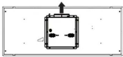
natural_image
Simple line drawing of a mechanical component with an upward arrow and internal components (no text or symbols)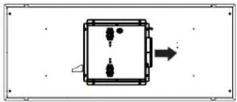
natural_image
Pure electrical circuit lines without any symbols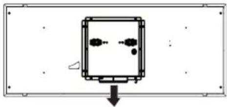
natural_image
Simple diagram of a rectangular frame with internal components and a downward arrow, no text or symbols present.natural_image
Technical line drawing of a mechanical assembly with a central box and hanging component (no text or symbols)2
natural_image
Technical line drawing of a mechanical device with a central circular component and two dashed lines indicating light paths (no text or symbols present)3
natural_image
Technical line drawing of a device rear panel with internal components and wiring (no text or symbols)natural_image
Technical line drawing of a mechanical assembly with a central box and hanging weights (no text or symbols)natural_image
Simple diagram of a rectangular box with internal compartments and an arrow pointing to one side (no text or symbols)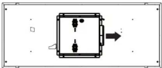
natural_image
Simple diagram of a rectangular device with internal components and an arrow indicating direction (no text or symbols)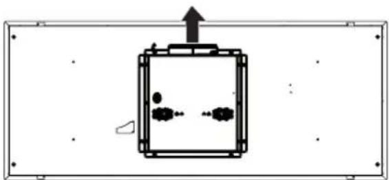
natural_image
Simple diagram of a device with an upward arrow and internal components, enclosed in a rectangular frame (no text or symbols)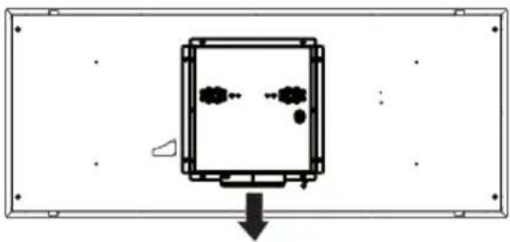
natural_image
Simple line drawing of a rectangular device with internal components and a downward arrow, no text or symbols present.natural_image
Technical line drawing of a device enclosure with internal components and wiring (no text or symbols)natural_image
Technical line drawing of a mechanical assembly with a central box and hanging weights (no text or symbols)natural_image
Illustration of hands installing or adjusting a mechanical component with a wall-mounted frame (no text or symbols)10.a
natural_image
Technical line drawing of a mechanical assembly with two rectangular components and mounting brackets (no text or symbols)| Campana | ||
| 36" 15 3/4" 23 5/8" | ||
| 48" 15 3/4" 31 5/8" |
natural_image
Top-down schematic of a rectangular device with internal components and labeled ports (no text or symbols)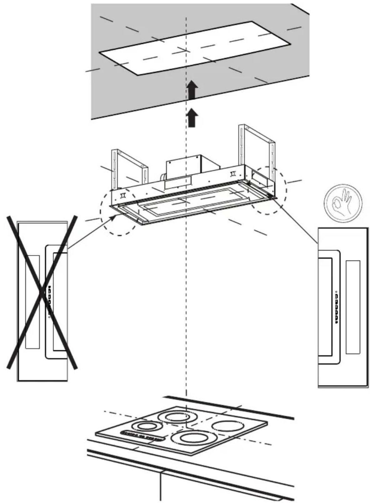
natural_image
Illustration of two hands performing a physical maneuver with a curved object underneath (no text or symbols)natural_image
Technical diagram of a mechanical device with two circular insets labeled A and B showing internal components (no text or symbols present)natural_image
Diagram of a folding cabinet with hand gestures and a close-up of the tray (no text or symbols)natural_image
Diagram of a hand pressing a button into a rack with a curved arrow indicating rotation (no text or symbols)natural_image
Diagram of a car with a circular vent and a green arrow indicating direction (no text or symbols)


