PTBM 500 C3 - Drill PARKSIDE - Free user manual and instructions
Find the device manual for free PTBM 500 C3 PARKSIDE in PDF.
User questions about PTBM 500 C3 PARKSIDE
0 question about this device. Answer the ones you know or ask your own.
Ask a new question about this device
Download the instructions for your Drill in PDF format for free! Find your manual PTBM 500 C3 - PARKSIDE and take your electronic device back in hand. On this page are published all the documents necessary for the use of your device. PTBM 500 C3 by PARKSIDE.
USER MANUAL PTBM 500 C3 PARKSIDE
TISCHBOHRMASCHINE / BENCH PILLAR DRILL / PERCEUSE D'ÉTABLI PTBM 500 D4
DE AT CH
TISCHBOHRMASCHINE
Translation of the original instructions
NL
BE
TAFELBOORMACHINE
Before reading, unfold the page containing the illustrations and familiarise yourself with all functions of the device.
FR BE
Extent of the delivery 23
Description of functions 23
Overview 23
Technical Data 23
Notes on safety. 24
Symbols and icons 24
General notes on safety 25
General Safety Instructions
for Power Tools 25
Assembly 28
Operation 28
Setting up 29
Selecting the speed 29
Checking the V-belts 30
Tensioning the V-belts 30
Adjusting the Drilling Bench. 30
Preselecting the Drilling Depth 30
Changing the Bit 30
Drilling 31
General Information 31
Switching on and off 31
Clamping the Workpieces 31
Removing Blockages 31
Cleaning and maintenance ....32
Cleaning 32
Maintenance 32
Storage 32
Transport 33
Waste disposal and environmental protection 33
Troubleshooting 33
Replacement parts/Accessories..34
Guarantee 35
Repair Service 36
Service-Center 36
Importer 36
Translation of the original EC declaration of conformity .... 125
Exploded Drawing 129
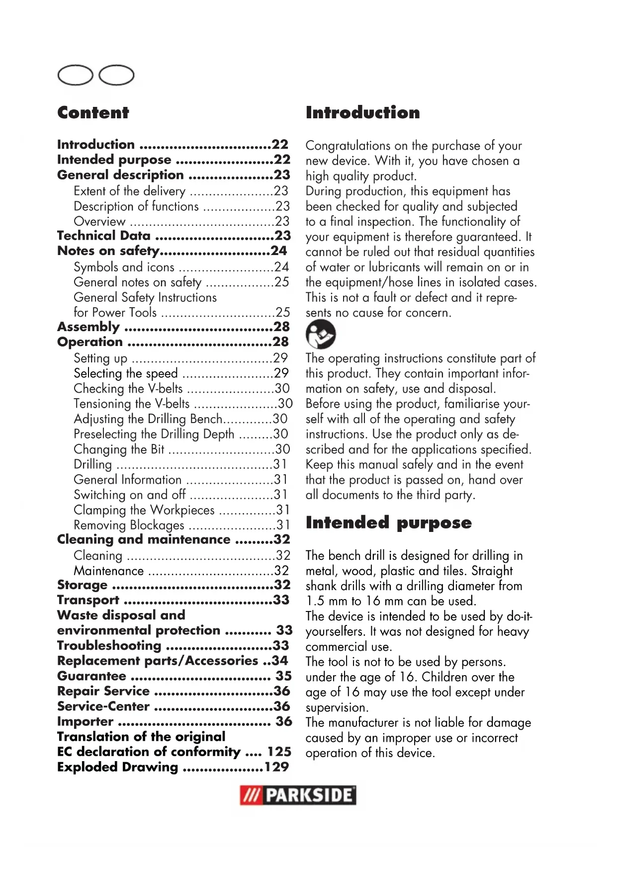
Introduction
Congratulations on the purchase of your new device. With it, you have chosen a high quality product.
During production, this equipment has been checked for quality and subjected to a final inspection. The functionality of your equipment is therefore guaranteed. It cannot be ruled out that residual quantities of water or lubricants will remain on or in the equipment/hose lines in isolated cases. This is not a fault or defect and it represents no cause for concern.

The operating instructions constitute part of this product. They contain important information on safety, use and disposal.
Before using the product, familiarise yourself with all of the operating and safety instructions. Use the product only as described and for the applications specified.
Keep this manual safely and in the event that the product is passed on, hand over all documents to the third party.
Intended purpose
The bench drill is designed for drilling in metal, wood, plastic and tiles. Straight shank drills with a drilling diameter from 1.5mm to 16mm can be used.
The device is intended to be used by do-it-yourselfers. It was not designed for heavy commercial use.
The tool is not to be used by persons under the age of 16. Children over the age of 16 may use the tool except under supervision.
The manufacturer is not liable for damage caused by an improper use or incorrect operation of this device.
General description

The illustration of the principal functioning parts can be found on the front and back foldout pages.
Extent of the delivery
Carefully unpack the appliance and check that it is complete. Dispose of the packaging material correctly.
-Baseplate
-Drilling bench
- Column tube
- Motor unit
- 3 drill lifting arms
- Safety device
- Drill chuck
- Drill chuck key
-Allenkey
Vice
- Mounting material
- Instruction Manual
Description of functions
Please refer to the descriptions below for information about the operating devices.
Overview

1 Off switch
2 On switch
3 Gear cover
4 Drill chuck
5 Emergency stop switch
6 Safety device
7 Drill spindle
8 Locking screw of the depth stop
9 Hand spindle guide with 3 drill lifting arms
10 Holder for drill chuck key
11 Locking screw for gear cover
12 Retaining screws for motor unit
13 Motor unit
14 Column tube
15 Locking handle
16 3 Assembly screws
17 Baseplate
18 Angle scaling
19 Retaining screw for drilling bench inclination
20 Drilling bench
21 Depth stop with scale
22 Vice mounting material
23 Vice
24 Chuck jaws
25 Allen key
26 Drill chuck key
27 Clamping screws for motor unit

28 Clamping screw for safety device

29 V-belt
30 Spindle-side drive pulley
31 Motor side drive pulley
32 Interlock switch
Technical Data
Bench Pillar Drill ....... PTBM 500 D4
Rated input voltage 230 V~, 50 Hz
Power input. 500 W (S2 15 min)* Idling speed (n_0)
Spindle 500 - 2500 min
Motor 1400 min
Safety class
Protection category.. IPX0
Weight 17 kg
Drill chuck.....B16 (1.5 mm to 16 mm)
Spindle stroke. 50 mm
Workpiece size. max. 60 mm
Sound pressure level
(L_pA) 71 dB(A); K_pA = 3 dB
Sound power level (L_WA) measured. 84 dB(A); K_WA = 3 dB guaranteed .87 dB(A) Vibration(a) 2,39 m/s²; K=1,5 m/s²
- After continuous operation of 15 minutes the drill stops until the device temperature deviates by less than 2K (2^) from the room temperature.
Levels of noise and vibration were determined according to the norms and regulations in the declaration of conformity.
The vibration emission value has been measured according to a standardised testing method and may be used for comparison with another electric tool. The indicated vibration emission value may also be used for an introductory assessment of the exposure.

Warning:
The vibration emission value whilst actually using the electrical tool may vary from the given values independently of the type and way in which the electric tool is used.
Try to keep the exposure to vibrations as low as possible. Examples of measures to reduce vibration exposure are the wearing of gloves when using the tool and limiting the working hours. For this purpose all parts of the operating cycle have to be considered (for example, times when the electric tool is switched off and times when it is switched on but running without any load).
Notes on safety

Caution! When using power tools, observe the following basic safety measures for the prevention of electric shocks and the risk of injury and fire.
Please read all these instructions before using this electric tool and please keep the safety instructions.
Symbols and icons
Symbols on the device:

Warning!

Warning! Electric shock hazard.
ays unplug the device before working on it.

Read the manual!

Wear ear protection

Wear eye protection

Do not wear long hair uncovered.
hair net.

Do not wear gloves.

Caution! Risk of injury from rotating parts!

Caution! Hot surface. There is a risk of burns.

Electrical machines do not belong with domestic waste
Symbols used in the instructions:

Hazard symbols with information on prevention of personal injury and property damage.

Precaution symbol with information on prevention of harm / damage.

Connect the machine to the power supply.

Pull out the mains plug.

Notice symbol with information on how to handle the device properly.
Steel

Wood
General notes on safety

Caution! When using power tools, observe the following basic safety measures for the prevention of electric shocks and the risk of injury and fire: There is a risk of injury.
General Safety Instructions for Power Tools

WARNING! Read all safety instructions and guidelines carefully. Failure to follow the safety instructions and guidelines may result in electric shock, fire and/or serious injuries.
Save all safety instructions and guidelines for the future.
The term "power tool" used in the safety instructions refers to mains-operated electric tools
(with a mains cable) and to battery-operated electric tools (without a mains cable).
Safe working
-
Keep your work area tidy. An untidy workplace can lead to accidents.
Consider environment influences -
Do not expose power tools to rain.
- Do not use power tools in damp or wet surroundings.
- Ensure the work area is adequately lit.
-
Do not use power tools where there is a fire or explosion hazard.
-
Protect yourself against electric shock. Avoid body contact with earthed parts (e.g. pipes, radiators, electric cookers, refrigerators).
- Keep other people away. Do not allow other people, especially children, to touch the power tool or cable. Keep them away from your work area.
- Store unused power tools safely. Unused power tools should be stored in a dry, high or locked place, out of the reach of children.
- Do not overload your power tool. They work better and more safely within the specified power range.
-
Use the correct power tool.
-
Do not use low-performance machines for heavy work.
- Do not use the power tool for purposes for which it is not intended. For example, do not use use a circular hand saw for cutting tree branches or logs.
- Wear suitable clothing
- Do not wear loose clothing or jewellery that might become caught in moving parts.
- When working outdoors, non-slip footwear is recommended.
-
Wear a hair net to contain long hair.
-
Use protective equipment
-
- Wear safety goggles.
- Use a dust mask for work which generates dust.
- Connect a dust extraction device. If connections are available for dust extraction and collection devices, make sure that these are connected and properly used.
- Do not use the cable for purposes for which it is not intended. Do not use the cable to pull the plug from the socket. Protect the cable from heat, oil and sharp edges.
- Secure the workpiece. Use jigs or a vice to hold the workpiece securely. This is safer than using your hand.
- Avoid abnormal body postures. Ensure secure footing and keep your balance at all times.
-
Maintain tools with care
-
Keep cutting tools sharp and clean for better and safer working.
- Follow the instructions for lubrication and changing tools.
- Regularly check the connection cable of the power tool and, if it is damaged, have it replaced by a qualified specialist.
- Check extension cords periodically and replace them if they are damaged.
-
Keep handles dry, clean and free from oil and grease.
-
Remove the plug from the mains socket when the power tool is not in use, before maintenance and when changing tools such as saw blades, drill bits, cutters.
- Do not allow any tool keys to remain inserted. Check, before switching on, that keys and adjusting tools have been removed.
-
Avoid unintentional starting.
Make sure that the switch is off when inserting the plug into the socket. -
Use extension cables outdoors. Only use approved and appropriately marked extension cables outdoors.
- Pay attention at all times. Pay attention to what you are doing. Work using common sense. Do not use the power tool if you cannot concentrate.
- Check the power tool for possib- le damage
Before further use of the power tool, safety devices or slightly damaged parts must be carefully examined in respect of their proper and intended function.
- Check that the moving parts are working properly and are not jammed or whether parts are damaged. All parts must be correctly fitted and satisfy all conditions to ensure the proper operation of the power tool.
- Damaged safety equipment and parts must be repaired properly or replaced by an authorised specialist workshop unless otherwise indicated in the instructions.
- Damaged switches must be replaced at a customer service workshop.
- Do not use power tools if the switch cannot be turned on and off.
CAUTION! The use of other bits and other accessories can result in a risk of personal injury.
- Have your power tool be repaired by a qualified electrician
- This power tool complies with the relevant safety regulations. Repairs may only be performed by a qualified electrician, using original spare parts; otherwise accidents involving the user may result.
Service:
- Have your power tool repaired only by qualified specialists and only with original spare parts. This will ensure that the power tool remains safe.
Safety Instructions for Box Column Drills
-
Never make the warning labels on the power tool illegible.
-
Attach the power tool to a solid, flat and horizontal surface. If the power tool can slip or wobble, the bit may not be guided smoothly and safely.
-
Keep the work area clean except for the workpiece to be machined. Sharp-edged drilling chips and objects can cause injury. Material mixtures are particularly dangerous. Light metal dust can burn or explode.
-
Set the correct speed before starting work. The speed must be appropriate for the drill diameter and the material to be drilled. At an incorrectly set speed the bit may get jammed in the workpiece.
Only when the device is turned on should the bit be moved against the work piece. Otherwise there is a danger that the bit will get jammed in the workpiece and the workpiece will rotate with the bit. This can lead to injuries.
-
Do not put your hands in the area of the drill while the power tool is running. Upon contact with the bit is a risk of injury.
-
Never remove drilling chips from the drilling area while the power tool is running. Always put the drive mechanism in the standby position first and then turn on the power tool.
-
Do not remove accumulated drill chips with your bare hands.
There is a risk of injury due to hot and sharp metal shavings in particular.
-
Break up long drilling chips by interrupting the drilling operation with a short backward rotation of the rotary wheel. Long drilling chips may cause injury.
-
Keep handles dry, clean and free from oil and grease. Greasy, oily handles are slippery and lead to loss of control.
Use clamps to hold the workpiece in place. Do not work on any workpieces that are too small for clamping. If you hold the workpiece by hand, you cannot hold it sufficiently tightly against rotation and may hurt yourself.
-
Switch the power tool off immediately if the bit jams. The bit jams when:
-
the power tool is overloaded or
-
the workpiece to be machined is jammed.
-
Do not touch the bit after working before it has cooled down. The bit is very hot during use.
-
Inspect the cable regularly and have a damaged cable repaired only by an authorised customer service centre. Replace damaged extension cables. This will ensure that the power tool remains safe.
-
Store unused power tools in a safe place. The storage place should be dry and lockable. This prevents the power tool from being damaged as a result of being stored or operated by inexperienced people.
-
Never leave the tool before it has come to a complete standstill. After-running bits can cause injury.
O O
- Do not use the power tool with a damaged cable. Do not touch the damaged cable and pull the mains plug if the cable is damaged while working. Damaged cables increase the risk of electric shock.
The device is unsuitable for processing of foods. - Edit not work pieces that you can not sure retain. Especially round or uneven workpieces.
- Avoid abnormal body postures. Ensure secure footing and keep your balance at all times.
Assembly
The bench drill is supplied disassembled. Clean the column tube (14), baseplate (17), drilling bench (20), vice (23) and the drill chuck (4) beforehand, with a dry cloth.
- Place the column tube (14) on the baseplate (17). Bolt the column tube (14) to the baseplate (17) with the three assembly srews (16) supplied. Tighten the assembly srews (16) moderately tight so that the threads in the baseplate (17) do not strip.
- Place the drilling bench (20) on the column tube (14). Push the drilling bench (20) into a lower position. Use the locking handle (15) to fix the drilling bench (20) in a lower position.

- Place the vice (23) on the drilling bench (20). Screw it firmly onto the drilling bench (20) by means of the enclosed assembly screws (22) together with the washer and the lock washer in the order as shown.

- Place the motor unit (13) on the column tube (14). Secure the motor unit (13) with the two clamping screws (27) on the side using the enclosed Allen key (25).

-
Bolt the three drill lifting arms into the spindle guide (9). Tighten the three hole lifting arms with a spanner (AF 6 mm).
-
Release the clamping screw from the depth stop (8).

-
Put the safety device (6) on the upper part of the drill spindle (7).
-
Secure the safety device (6) with the clamping screw (28).
-
Fold the safety device (6) upwards. Insert the chuck (4) on the taper of the drill spindle (7). Push the drill chuck onto the drill chuck tip with a few light taps. Use a plastic hammer for this purpose.
Operation

Caution! Risk of injury!
- Ensure that you have sufficient space in which to work and that you do not endanger other people.
- All hoods and protective devices must be assembled properly before commissioning.
- Disconnect the mains plug before changing the setting on the device.
Setting up
Place the bench drill on a solid surface. Ideally, bolt the drill to the surface. Use the four holes in the baseplate (17) for this.

Selecting the speed
- Release the locking bolt (11) on the gear cover (3).
- Open the gear cover (3).
- Release the two retaining bolts (12) on the motor unit (13).
- Slide the motor unit (13) forward a little to release the load on the V-belts (29).
- Place the V-belts (29) on the desired assembly to reach the specified speed:
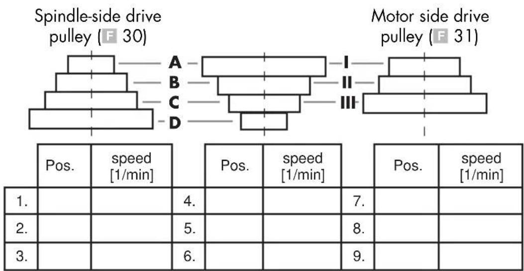

The gear cover (3) is equipped with a interlock switch (32). If the gear cover (3) is not closed correctly, the device cannot be switched on.
- Slide the motor unit (13) back to tension on the V-belts (29) again.
- The V-belts (29) are correctly tensioned when they give way slightly when pressed.
- Tighten the retaining bolts (12) on the motor unit (13) again.
- Close the gear cover (3). Fasten the locking bolt (11) on the gear cover.
Recommended speeds for different drill sizes and materials:
| [mm] | [mm] | [1/min] |
| <3 | <4 | 2500 |
| 3-4 5 | -6 1600 | |
| 5 | 7-8 1 | 100 |
| 6-8 9 | 10 830 | |
| >8 | >10 | 500 |
Checking the V-belts
- Release the locking bolt (11) on the gear cover (3).
- Open the gear cover (3).
- Check the tension of the V-belts (29).
- The V-belts (29) are correctly tensioned when they give way slightly when pressed.
- Check the V-belts (29) for tears, cuts or other damage.
- Close the gear cover (3). Fasten the locking bolt (11) on the gear cover (3).
Tensioning the V-belts
- Release the locking bolt (11) on the gear cover (3).
- Open the gear cover (3).
- Release the retaining bolts (12) on the motor unit (13).
- Slide the motor unit (13) back to tension on the V-belts (29).
- The V-belts (29) are correctly tensioned when they give way slightly when pressed.
- Tighten the retaining bolts (12) on the motor unit (13) again.
- Close the gear cover (3). Fasten the locking bolt (12) on the gear cover (3).
Adjusting the Drilling Bench
- Release the locking handle (15).
- Push the drilling bench (20) to the desired height.
- Pivot the drilling bench (20) to the desired position.
- Fasten the drilling bench (20) again with the locking handle (15).
- You can also adjust the tilt angle of the drilling bench (20). To do this, release the retaining screw (19) (AF 19 mm) under the drilling bench (20). Tilt the
drilling bench (20) as desired to the right or left up to a max. of 45^ and secure the drilling bench (20) again with the retaining screw (19).
Preselecting the Drilling Depth
- Release the locking screw from the depth stop (8).
- Lower the drilling spindle (7) with the mounted tool on to the workpiece.
- Turn the scale until the silver marking arrow attached to the motor unit (13) is pointing to the zero line of the scale.
- Now turn the scale to the desired drilling depth and tighten the locking screw (8) again.
- Turn the drilling spindle (7) back to its starting position.
Changing the Bit

Remove the plug from the mains socket before changing the bit. This will prevent an accidental start-up.
- Fold the safety device (6) up.
- Release the retaining jaws of the drill chuck (4) with the drill chuck key (26) you find in the holder (10).
- Remove the bit.
- Insert a new bit.
- Tighten the retaining jaws of the drill chuck (4) with the drill chuck key (26).
- Affix the hole chuck key (26) on the holder again (10).
- Check that the bit is centred.
- Fold the safety device (6) down again.
- Carry out a brief trial run in order to check the drill for true running.

Under no circumstances must you leave the drill chuck key (26) inserted.
Drilling
- Turn the appliance on.
- Turn one of the drill lifting arms anticlockwise
- The drill chuck (4) is lowered.
- Drill into the workpiece at the appropriate feed rate and to the desired depth.
- Be aware of any necessary chip breaking on the way to the desired depth.
- Move the bit slowly back to the stop position.
General Information

The feed rate and spindle speed are decisive for the service life of the bit.
- The cutting speed is determined by the speed of the drill spindle and by the diameter of the bit.
In principle, therefore, the larger the bit diameter, the lower the speed that should be selected. - For workpieces of greater strength, the cutting pressure must be higher.
- Repeated withdrawal of the bit enables easier chip removal.
- Chip removal is especially difficult in deep holes. Reduce the feed rate and speed in this case.
- To avoid excessive wear on the cutting surface of the bit, for drill holes over 8.0mm in diameter you should first drill with a bit with a smaller diameter.
Switching on and off

Make sure that the power supply voltage matches the voltage rating indicated on the device's type plate.

Connect the machine to the power supply.

Caution! Fold the protective device (6) down before you switch on the machine.
Switching on:
Press the on switch (2).
Switching off:
Press the off switch (1).
Emergency stop:
Press the emergency stop button (5).

After pressing the emergency stop button, the emergency stop button (5) must be activated again by turning it. Press the on switch (2) to restart the device.
Clamping the Workpieces
Only work with workpieces that can be securely clamped. The workpiece must not yield too much. Otherwise it is nor possible to apply adequate tension.
The workpiece must not be too small or too large either.
Removing Blockages
- You should always select a suitable feed rate which allows trouble-free chip breaking.
- If the bit is jammed in the workpiece, turn off the power and unplug the power cord. Turn the bit on the drill chuck anticlockwise with a little jerk to break the chip and release the bit again.
- If a fragment is produced during the processing of the workpiece, turn off the power and unplug the power cord. Use a pair of pliers and remove the fragment to prevent it flying off in an uncontrolled way.
Cleaning and maintenance

Pull the mains plug before any adjustments, maintenance or repair.

Have any work on the device that is not described in this instruction guide performed by a professional. Only use original parts. Allow the device to cool off before any maintenance or cleaning is undertaken. There is a risk of burning!
Always check the device before using it for obvious defects such as loose, worn or damaged parts, correct the positioning of screws or other parts. Exchange the damaged parts.
Cleaning

Do not use any cleaning agents or solvents. Chemical substances can etch the plastic parts of the device. Never clean the device under running water.
- Thoroughly clean the device after every use.
- Clean the ventilation openings and the surface of the device with a soft brush or cloth.
- Remove chips, dust and dirt with a vacuum cleaner if necessary.
- Lubricate moving parts regularly.
- Do not allow lubricants to come into contact with switches, V-belts, pulleys and drill lifting arms.

Maintenance

Repeat the maintenance after every 5 hours of operation.
- Release the locking bolt (A 11) on the gear cover (3).
- Open the gear cover (3).
- Release the two retaining bolts (12) on the motor unit (13).
- Slide the motor unit (13) forward a little to release the load on the V-belts (F 29).
- Remove both V-belts (F29).
- Remove the middle drive disc (33) and its retainer (34).
- Clean the bearing point retainer (35 + 36) and grease this with a commercially available multi-purpose grease.
- Re-insert the retainer (34) and the drive disc (33). Tighten the V-belts (F 29) again.
- Slide the motor unit (13) back to tension on the V-belts (F29) again.
- The V-belts (F 29) are correctly tensioned when they give way slightly when pressed.
11.Tighten the retaining bolts (12) on the motor unit (13) again.
12.Close the gear cover (3). Fasten the locking bolt (A 11) on the gear cover.
Storage
- Store the appliance in a dry place well out of reach of children.
The device can be relocated over a short distance with two people. Relocating the device over a longer distance generally has to take place with a transport aid.
Transport

Do not carry the bench drill holding it on the motor unit.

Caution! Hot surface. There is a risk of burns. Only transport the machine when the motor unit (A 13) has cooled down completely.
If possible, carry the bench drill together with another person. Grip the baseplate (A 17) with one hand and stabilise the machine on the drive cover (A 3) with the other hand.
Waste disposal and environmental protection
Be environmentally friendly. Return the tool, accessories and packaging to a recycling centre when you have finished with them.
Electrical machines do not belong with domestic waste.
- Hand over the device at an utilization location. The plastic and metal parts employed can be separated out and thus recycled use can be implemented. Ask our Service-Center for details.
Defective units returned to us will be disposed of for free.
Troubleshooting
| Problem | Possible Cause | Error correction |
| Device doesn't start | Emergency stop switch (5) has been triggered | Reactivate the emergency stop switch (5) by turning it. Press the on switch (1) to restart the device |
| No mains voltageMain circuit breaker is tripped | Check the socket, mains supply cable, cord, mains plug; if necessary, have them repaired by a qualified electrician. Check the main fuse | |
| On/off switch (1/2) is broken | Repair by Customer Care | |
| Motor faulty | Repair by Customer Care | |
| Strong vibrations | Motor unit (13) not fi xed in place | Check V-belt tension and tighten the locking screw (12) |
| Bit not centrally clamped | Check the bit in the drill chuck (4) | |
| Loud squeaking noise | V-belt tension is too high | Check V-belt tension |
| Damaged V-belts (29) | Check V-belts (29) | |
| Damaged pulley | Check pulleys |
Replacement parts/Accessories
Spare parts and accessories can be obtained at www.grizzly-service.eu
If you do not have internet access, please contact the Service Centre via telephone (see "Service-Center" page 36). Please have the order number mentioned below ready.
| Position Manual | Position drawing | Description | Ordernumb |
| A 6 | 11-22 | Safety device, complete 91103336 | |
| A 20 | 5-9 | Drilling bench, complete 91104522 | |
| A 1/2 | 44,46-51,54 | On-/Off switch, complete 91103339 | |
| A 5 | 31-36 | Emergency stop switch 91104503 | |
| A 9 | 67,68 | Drill lift arm | 91104507 |
| A 23 | 79-83 | Vice | 91103342 |
| F 29 | 102 | V-belt, set | 91104508 |
| A 4 | 23 | Drill chuck | 91104502 |
| 120,121 | Hinge of the gear cover | 91104509 | |
| A 8 | 65 | Screw for depth limiter | 91104506 |
| 37 | Spring for spindle return | 91104504 | |
| A 12 | 53 | Screw for V-belt tension | 91104505 |
| A 26 | 70 | Drill chuck key | 91104510 |
Guarantee
Dear Customer,
This equipment is provided with a 3-year guarantee from the date of purchase.
In case of defects, you have statutory rights against the seller of the product. These statutory rights are not restricted by our guarantee presented below.
Terms of Guarantee
The term of the guarantee begins on the date of purchase. Please retain the original receipt. This document is required as proof of purchase.
If a material or manufacturing defect occurs within three years of the date of purchase of this product, we will repair or replace - at our choice - the product for you free of charge. This guarantee requires the defective equipment and proof of purchase to be presented within the three-year period with a brief written description of what constitutes the defect and when it occurred.
If the defect is covered by our guarantee, you will receive either the repaired product or a new product. No new guarantee period begins on repair or replacement of the product.
Guarantee Period and Statutory Claims for Defects
The guarantee period is not extended by the guarantee service. This also applies for replaced or repaired parts. Any damages and defects already present at the time of purchase must be reported immediately after unpacking. Repairs arising after expiry of the guarantee period are chargeable.
Guarantee Cover
The equipment has been carefully produced in accordance with strict quality guidelines and conscientiously checked prior to delivery.
The guarantee applies for all material and manufacturing defects. This guarantee does not extend to cover product parts that are subject to normal wear and may therefore be considered as wearing parts (e.g. V-belts) or to cover damage to breakable parts (e.g. switches).
This guarantee shall be invalid if the product has been damaged, used incorrectly or not maintained. Precise adherence to all of the instructions specified in the operating manual is required for proper use of the product. Intended uses and actions against which the operating manual advises or warns must be categorically avoided.
The product is designed only for private and not commercial use. The guarantee will be invalidated in case of misuse or improper handling, use of force, or interventions not undertaken by our authorised service branch.
Processing in Case of Guarantee
To ensure efficient handling of your query, please follow the directions below:
-
Please have the receipt and item number (IAN 290757) ready as proof of purchase for all enquiries.
-
Please find the item number on the rating plate.
-
Should functional errors or other defects occur, please initially contact the service department specified below by telephone or by e-mail. You will then receive further information on the processing of your complaint.
-
After consultation with our customer service, a product recorded as defective can be sent postage paid to the service address communicated to you, with the proof of purchase (receipt) and specification of what constitutes the defect and when it occurred. In order to avoid acceptance problems and additional costs, please be sure to use only the address communicated to you. Ensure that the consignment is not sent carriage forward or by bulky goods, express or other special freight. Please send the equipment inc. all accessories supplied at the time of purchase and ensure adequate, safe transport packaging.
Repair Service
For a charge, repairs not covered by the guarantee can be carried out by our service branch, which will be happy to issue a cost estimate for you. We can handle only equipment that has been sent with adequate packaging and postage.
Attention: Please send your equipment to our service branch in clean condition and with an indication of the defect.
Equipment sent carriage forward or by bulky goods, express or other special freight will not be accepted.
We will dispose of your defective devices free of charge when you send them to us.
Service-Center
Service Great Britain
Tel.: 0871 5000 720
(£ 0.10/Min.)
E-Mail: grizzly@lidl.co.uk
IAN 290757
Service Ireland
Tel.: 1890 930 034
(0,08 EUR/Min., (peak))
(0,06 EUR/Min., (off peak))
E-Mail: grizzly@lidl.ie
IAN 290757
Importer
Please note that the following address is not a service address. Please initially contact the service centre specified above.
Puisance absorbee. 500 W (S2 15 min)*
| Translation of the original EC declaration of conformity | |
| We hereby confirm that the Bench Pillar Drill Design Series PTBM 500 D4 Serial Number 201710000001 - 201710200000 conforms with the following applicable relevant version of the EU guidelines : | |
| 2006/42/EC • 2014/30/EU • 2011/65/EU* | |
| In order to guarantee consistency, the following harmonised standards as well as national standards and stipulations have been applied: | |
| EN 61029-1:2009/A11:2010 • EN ISO 12100:2010 EN 55014-1:2006/A2:2011 • EN 55014-2:2015 EN 61000-3-2:2014 • EN 61000-3-3:2013 • EN 62321:2009 | |
| This declaration of conformity is issued under the sole responsibility of the manufacturer: | |
| CE Grizzly Tools GmbH & Co. KG Stockstädter Straße 20 63762 Großbostheim GERMANY 17.11.2017 | Christian Frank ( Documentation Representative ) |
*The object of the declaration described above satisfies the provisions of Directive 2011/65/EU of the European Parliament and the Council of 8 June 2011 on limiting the use of certain harmful substances in electrical and electronic appliances.