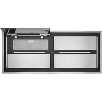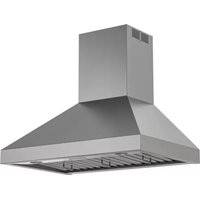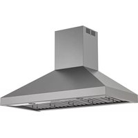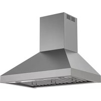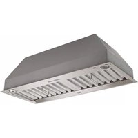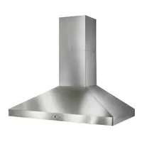
Colonne WPP9IQ36SB - Basket BEST - Free user manual and instructions
Find the device manual for free Colonne WPP9IQ36SB BEST in PDF.


User questions about Colonne WPP9IQ36SB BEST
0 question about this device. Answer the ones you know or ask your own.
Ask a new question about this device
Download the instructions for your Basket in PDF format for free! Find your manual Colonne WPP9IQ36SB - BEST and take your electronic device back in hand. On this page are published all the documents necessary for the use of your device. Colonne WPP9IQ36SB by BEST.
USER MANUAL Colonne WPP9IQ36SB BEST
natural_image
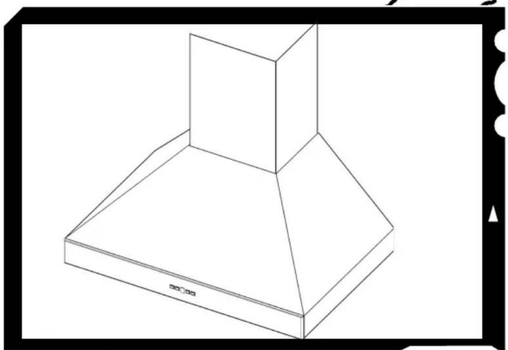
Line drawing of a 3D isometric kitchen range hood (no text or symbols)Model WPP9
ENGLISH....3
FRANÇAIS......25
ESPAÑOL......49
In USA - BEST Hartford, Wisconsin
In CANADA - BEST Drummondville, QC, Canada
REGISTER YOUR PRODUCT ONLINE AT : www.BestRangeHoods.com/register For additional Information visit www.BestRangeHoods.com
READ AND SAVE THESE INSTRUCTIONS
- Use this unit only in the manner intended by the manufacturer. If you have questions, contact the manufacturer at the address or telephone number listed in the warranty.
- Before servicing or cleaning unit, switch power off at service panel and lock service panel to prevent power from being switched on accidentally. When the service disconnecting means cannot be locked, securely fasten a prominent warning device, such as a tag, to the service panel.
- Installation work and electrical wiring must be done by a qualified person(s) in accordance with all applicable codes and standards, including fire-rated construction codes and standards.
- Sufficient air is needed for proper combustion and exhausting of gases through the flue (chimney) of fuel burning equipment to prevent backdrafting. Follow the heating equipment manufacturer's guidelines and safety standards such as those published by the National Fire Protection Association (NFPA), and the American Society for Heating, Refrigeration and Air Conditioning Engineers (ASHRAE), and the local code authorities.
- When cutting or drilling into wall or ceiling, do not damage electrical wiring and other hidden utilities.
- Ducted fans must always be vented to the outdoors.
- Do not use this unit with any separate solid-state speed control device.
- To reduce the risk of fire, use only steel ductwork.
GROUNDING INSTRUCTIONS
This appliance must be grounded. In the event of an electrical short circuit, grounding reduces the risk of electrical shock by providing an escape wire for the electric current.
WARNING - Improper grounding can result in a risk of electric shock.
Consult a qualified electrician if the grounding instructions are not completely understood, or if doubt exists as to whether the appliance is properly grounded.
Do not use an extension cord. Have a qualified electrician install an outlet near the appliance.
TO REDUCE THE RISK OF A RANGE TOP GREASE FIRE:
A. Never leave surface units unattended at high settings. Boilovers cause smoking and greasy spillovers that may ignite. Heat oils slowly on low or medium settings.
B. Always turn hood ON when cooking at high heat or when flambeing food (i.e. Crepes Suzette, Cherries Jubilee, Peppercorn Beef Flambe').
C. Clean ventilating fans frequently. Grease should not be allowed to accumulate on fan or filter.
D. Use proper pan size. Always use cookware appropriate for the size of the surface element.
TO REDUCE THE RISK OF INJURY TO PERSONS IN THE EVENT OF A RANGE TOP GREASE FIRE, OBSERVE THE FOLLOWING:\*
- SMOTHER FLAMES with a close-fitting lid, cookie sheet, or metal tray, then turn off the burner. BE CAREFUL TO PREVENT BURNS. If the flames do not go out immediately, EVACUATE AND CALL THE FIRE DEPARTMENT.
- NEVER PICK UP A FLAMING PAN - You may be burned.
- DO NOT USE WATER, including wet dishcloths or towels - violent steam explosion will result.
- Use an extinguisher ONLY if:
A. You know you have a Class ABC extinguisher and you already know how to operate it.
B. The fire is small and contained in the area where it started.
C. The fire department is being called.
D. You can fight the fire with your back to an exit.
* Based on "Kitchen Fire Safety Tips" published by NFPA.
CAUTION
- For indoor use only.
- To reduce risk of fire and to properly exhaust air, be sure to duct air outside. Do not vent exhaust air into spaces within walls or ceilings or into attics, crawl spaces, or garages.
- Take care when using cleaning agents or detergents.
- Avoid using food products that produce flames under the Range Hood.
- For general ventilating use only. Do not use to exhaust hazardous or explosive materials and vapors.
- To avoid motor bearing damage and noisy and/or unbalanced impellers, keep drywall spray, construction dust, etc. off power unit.
- Your hood motor has a thermal overload which will automatically shut off the motor if it becomes overheated. The motor will restart when it cools down. If the motor continues to shut off and restart, have the hood serviced.
- For best capture of cooking impurities, the bottom of the hood should be a minimum of 24" and a maximum of 36" above the cooking surface.
- Two installers are recommended because of the large size and weight of this hood.
- This product is equipped with a thermostat which may start blower automatically. To reduce the risk of injury and to prevent power from being switched on accidentally, switch power off at service panel and lock or tag service panel.
- Please read specification label on product for further information and requirements.
- EXTERNAL BLOWER MODELS ONLY: To reduce risk of fire and electric shock, install this range hood only with Best Exterior Blower Models EB6, EB9, EB12 or EB15 or Best In-Line Blower Models ILB3, ILB6, ILB9 or ILB11. Other blowers cannot be substituted. (Blower sold separately)
Proper maintenance of the Range Hood will assure proper performance of the unit.
Motor
The motor is permanently lubricated and never needs oiling. If the motor bearings make excessive or unusual noise, replace the motor with the exact service motor. The impeller should also be replaced.
Grease Filter
The grease filters should be cleaned frequently. Use a warm detergent solution. Grease filter are dishwasher safe.
Clean all-metal filters in the dishwasher using a non-phosphate detergent. Discoloration of the filter may occur if using phosphate detergents, or as a result of local water conditions - but this will not affect filter performance. This discoloration is not covered by the warranty. See “INSTALL FILTERS” section for removal and installation instructions.
Drip Tray
The drip tray should be cleaned once a month or as needed. To remove the drip tray, first remove the baffle grease filters. Grasp both ends of the drip tray. Gently lift the drip tray up until the bottom of it clears the track. Pull the drip tray forward, being careful not to spill the contents, and move it to a nearby trash receptacle. To clean the drip tray, drain and wipe all excess grease with a dry paper towel. Wash with warm soapy water or in the dishwasher. Dry with a clean cloth. To replace the drip tray, lift it up and into the track on the hood. Reinstall baffle grease filters.
Non-ducted Recirculation Filter
The non-ducted recirculation filter should be changed every 6 months. Replace more often if your cooking style generates extra grease, such as frying and wok cooking. See “INSTALL FILTERS” section for removal and installation instructions.
natural_image
Technical diagram showing a mechanical assembly with arrows indicating motion or force direction (no text or symbols present)Stainless Steel Cleaning
DO:
- Regularly wash with clean cloth or rag soaked with warm water and mild soap or liquid dish detergent.
• Always clean in the direction of original polish lines.
• Always rinse well with clear water (2 or 3 times) after cleaning. Wipe dry completely. - You may also use a specialized household stainless steel cleaner.
DON'T:
- Use any steel or stainless steel wool or any other scrapers to remove stubborn dirt.
- Use any harsh or abrasive cleansers.
- Allow dirt to accumulate.
- Let plaster dust or any other construction residues reach the hood. During construction/renovation, cover the range hood to make sure no dust sticks to the stainless steel surface.
Avoid: When choosing a detergent
- Any cleaners that contain bleach will attack stainless steel
- Any products containing: chloride, fluoride, iodide, bromide will deteriorate surfaces rapidly.
- Any combustible products used for cleaning such as acetone, alcohol, ether, benzol, etc., are highly explosive and should never be used close to a range.
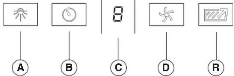
Controls (Fig.1)
flowchart
graph TD
    A["A"] --> D["8"]
    B["B"] --> D
    C["C"] --> D
    D --> E["D"]
    D --> F["R"]
Button A = turns the lights on/low/high/off.
Button B = Activates/Deactivates the delay-off feature. Press once (when blower is on) to activate the delay-off feature. The selected speed level that is displayed in display "C" will blink when this feature is activated. After 10 minutes, the blower will then turn off. Delay can be deactivated at any time by pressing the button again.
Display C = Indicates the selected speed of the blower 1, 2, 3, or b for boost.
“-” indicates the need to clean the grease filter or replace the non-duct filter.
Button D = Turns on the blower. Hood will turn on to the last speed selected. The blower speed will change each time the button is pushed (from 1 to "b"). To turn the blower off, press and hold button for approximately 2 seconds.
Button R = Filter clean indicator reset. Press and hold for 2 seconds to reset the indicator.
Auto Shut-Off Feature
If the blower and/or the lights are on continuously for 10 hours without any user interaction with the controls, the hood will automatically shut off. Press any control button to re-activate the hood.
HEAT SENTRY™
Your hood is equipped with a HEAT SENTRY™ thermostat. This thermostat is a device that will turn on or speed up the blower if it senses excessive heat above the cooking surface.
1) If blower is OFF - it turns blower ON to HIGH speed.
2) If blower is ON at a lower speed setting - it turns blower up to HIGH speed.
When the temperature level drops to normal, the blower will return to its original setting.
WARNING
The HEAT SENTRY thermostat can start the blower even if the hood is turned OFF. When this occurs, it is impossible to turn the blower OFF with its switch. If you must stop the blower, do it from the main electrical panel.
HALOGEN BULBS
This range hood requires 3 or 4 halogen bulbs (based on size of hood) (Type T4, 120 Volt, 25 Watt Max, G9 Base).

WARNING: Always switch off the electrical supply before carrying out any operation on the reliance.
To change bulbs:
-
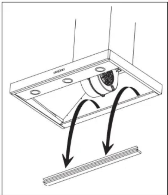
Open the cover by gently prying from proper slots (Fig.2).
-
Remove the bulb by pulling sideways (DO NOT ROTATE).

CAUTION: Bulb may be hot.
- Replace with Type T4, 120 Volt, 25 Watt Max, G9 Base halogen bulbs. Do not touch replacement bulbs with bare hands!
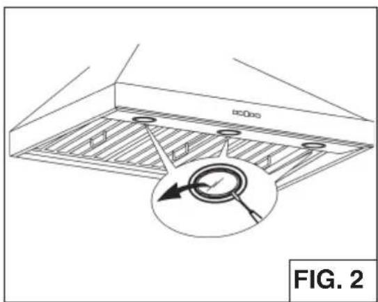
text_image
FIG. 2PREPARE THE HOOD
Unpack hood and check contents.
You should receive:
1 - Hood
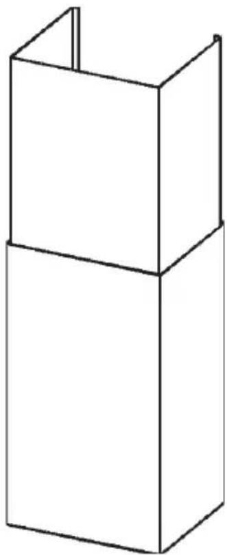
1 - Decorative Flues
1 - Parts Bag (B080810995) containing:
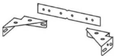
1 - Flue Mounting Bracket Set
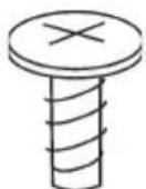
2 - Mounting Screws (3,9 x 6mm Flat Head)
2 - Mounting Screws (3,9 x 9,5mm Pan Head)
4 - Mounting Lag Screws (6 x 60mm)
2 - Mounting Screws (4,8 x 38mm Pan Head)
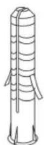
2 - Drywall Anchors
1 - Installation Instructions
natural_image
Simple line drawing of a three-tiered rectangular box (no text or symbols)DECORATIVE FLUES
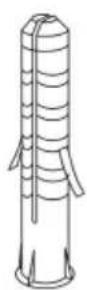
2 DRYWALL
ANCHORS
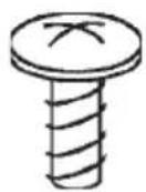
2 MOUNTING
SCREWS (3,9x9,5mm
Pan Head)
2 MOUNTING
SCREWS (3,9x6mm
Flat Head)
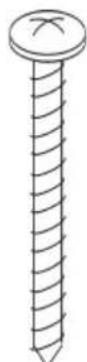
2 MOUNTING SCREWS (4,8x38mm Pan Head)
natural_image
Technical line drawing of three metal bracket assemblies with mounting holes (no text or symbols)FLUE MOUNTING BRACKET SET

4 MOUNTING LAG
SCREWS (6x60mm)
FIG. 3
EXTERIOR AND IN-LINE BLOWER SELECTION WPP9E Series
CAUTION: To reduce risk of fire and electric shock, install this range hood only with Best Exterior Blower Models EB6, EB9, EB12 or EB15, and Best In-Line Blower Models ILB3, ILB6, ILB9 or ILB11. Other blowers cannot be substituted.
The blower must be UL listed for Canadian and U.S. use, and evaluated for use with solid state speed control, rated 120V, 60 Hz, 6.0 A max.
INSTALL THE DUCTWORK WPP9E Series
NOTE: To reduce the risk of fire, use only metal ductwork.
- Choose the location where the Exterior Blower or In-Line Blower will be mounted. See illustrations below for mounting location suggestions and restrictions.
- A straight, short duct run will allow the hood to perform most efficiently.
- Long duct runs, elbows and transitions will reduce the performance of the hood. Use as few of them as possible. Larger ducting may be required for best performance with long duct runs.
- After the Exterior or In-Line Blower has been installed, connect round metal ductwork and work back towards the hood location. Use duct tape to seal joints between ductwork sections.
EXTERIOR BLOWER
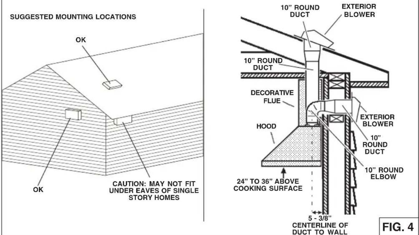
text_image
SUGGESTED MOUNTING LOCATIONS OK CAUTION: MAY NOT FIT UNDER EAVES OF SINGLE STORY HOMES 10" ROUND DUCT EXTERIOR BLOWER 10" ROUND DUCT DECORATIVE FLUE HOOD EXTERIOR BLOWER 10" ROUND DUCT 10" ROUND ELBOW 24" TO 36" ABOVE COOKING SURFACE 5 - 3/8" CENTERLINE OF DUCT TO WALL FIG. 4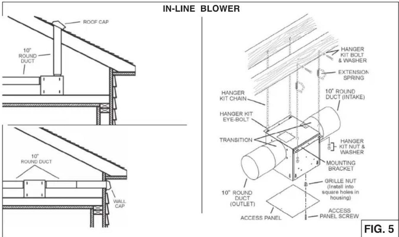
text_image
IN-LINE BLOWER ROOF CAP 10" ROUND DUCT 10" ROUND DUCT WALL CAP HANGER KIT CHAIN HANGER KIT EYE-BOLT TRANSITION 10" ROUND DUCT (OUTLET) ACCESS PANEL HANGER KIT BOLT & WASHER EXTENSION SPRING 10" ROUND DUCT (INTAKE) HANGER KIT NUT & WASHER MOUNTING BRACKET GRILLE NUT (Install into square holes in housing) ACCESS PANEL SCREW FIG. 5INSTALL THE DUCTWORK (WPP9IQ and WPP9IQT)
NOTE: To reduce the risk of fire, use only metal ductwork.
- Decide where the ductwork will run between the hood and the outside.
- A straight, short duct run will allow the hood to perform most efficiently.
It is recommended that there be a minimum of 6" of straight duct from to an elbow for 8" duct and 12" for 10" duct. - Long duct runs, elbows, and transitions will reduce the performance of the hood. Use as few of them as possible.
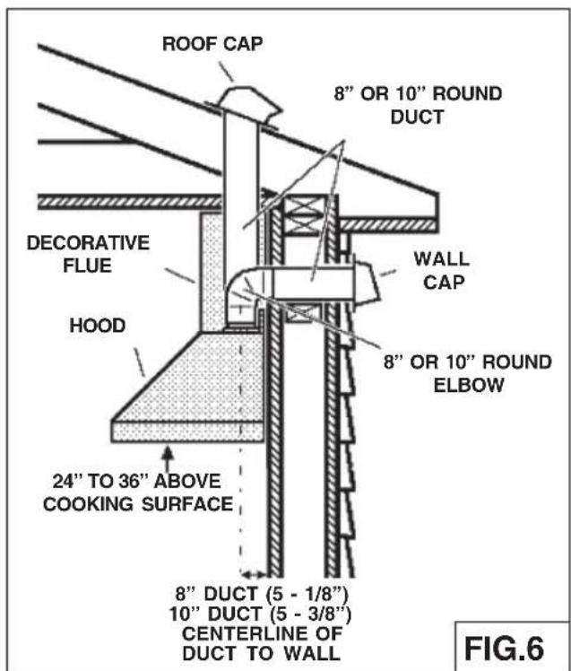
- Install a roof or wall cap. Connect 8" WPPIQ (or 10" WPPIQT) round metal ductwork to cap and work back towards hood location. Use duct tape to seal the joints between ductwork sections (Fig.6).
text_image
ROOF CAP 8" OR 10" ROUND DUCT Decorative Flue HOOD WALL CAP 8" OR 10" ROUND ELBOW 24" TO 36" ABOVE COOKING SURFACE 8" DUCT (5 - 1/8") 10" DUCT (5 - 3/8") CENTERLINE OF DUCT TO WALL FIG.6Remove the plastic protective film from all exterior surfaces, decorative flues and filters, prior to final installation
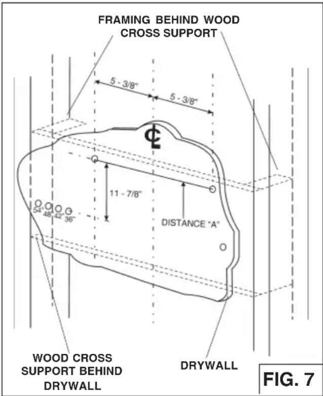
- Construct wood wall framing that is flush with interior surface of wall studs (Fig.7).
Make sure:
a) the framing is centered over installation location.
b) the height of the framing will allow the hood to be secured to the framing within the dimensions shown.
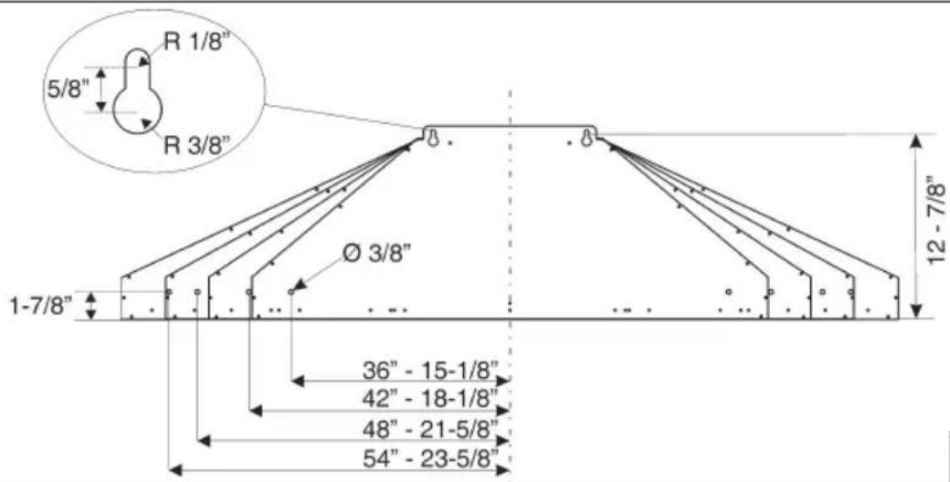
2. Install the (2) 6 x 60mm screws for the top of the hood at the dimensions shown in Fig.8-9. Use the two outer keyhole slots, do not completely tighten the screws.
3. Hang the hood onto the screws.
4. Level the hood and secure (2) 6 x 60mm screws at the outer locations of the hood. Tighten all (4) screws.
Notes:
a. Minimum hood distance above cook top must not be less than 24". A maximum of 36" above cook top is highly recommended for best capture of cooking impurities. Distances over 36" are the installer and user discretion.
text_image
FRAMING BEHIND WOOD CROSS SUPPORT 5 - 3/8" 5 - 3/8" Φ 11 - 7/8" DISTANCE "A" WOOD CROSS SUPPORT BEHIND DRYWALL DRYWALL FIG. 7| Ceiling Height | Duct Method | Hood Distance Above 36" High Cok Top (in.) | ||||||||||||
| 24 | 25 | 26 | 27 | 28 | 29 | 30 | 31 | 32 | 33 | 34 | 35 | 36 | ||
| Mounting Bracket Center Hole Location Above 36" High Cook Top (in.) see Fig.7 | ||||||||||||||
| 44 | 45 | 46 | 47 | 48 | 49 | 50 | 51 | 52 | 53 | 54 | 55 | 56 | ||
| 1/4 | 1/4 | 1/4 | 1/4 | 1/4 | 1/4 | 1/4 | 1/4 | 1/4 | 1/4 | 1/4 | 1/4 | 1/4 | ||
| 8 Feet | Ducted | X | X | X | X | X | X | X | X | X | ||||
| Non-Ducted | X | X | X | X | X | X | ||||||||
| 9 Feet | Ducted | X* | X* | X* | X | X | X | X | ||||||
| Non-Ducted | X | X | X | X | X | X | X | |||||||
| 10 Feet(see note b) | Ducted | X | X | X | X | X | X | X | X | X | X | |||
| Non-Ducted | X | X | X | X | X | X | X | X | X | X | ||||
| 11 Feet(see note a & b) | Ducted | X | X | X | X | X | ||||||||
| Non-Ducted | X | X | X | X | X | |||||||||
X = Possible Installation Heights
X* = Possible Installation Heights but the Non-Duct Filter Slots will be exposed on WPP9IQ36SB & WPP9IQ42SB
Notes:
a. Minimum hood distance above cook top must not be less than 24". A maximum of 36" above cook top is highly recommended for best capture of cooking impurities. Distances over 36" are at the installer and the users discretion; and if ceiling height and flue lenght permit.
b. Requires optional 10' flue extension, ducted model AEWPP9SB or non-ducted model AEWPP9SBN.

text_image
MOUNTING LAG SCREWS (6x60mm) 5-3/8" 5-3/8" MOUNTING LAG SCREWS (6x60mm) WALL FRAMINGFIG. 8
text_image
R 1/8" 5/8" R 3/8" Ø 3/8" 1-7/8" 36" - 15-1/8" 42" - 18-1/8" 48" - 21-5/8" 54" - 23-5/8" 12 - 7/8"FIG. 9
WIRING (WPP9IQ and WPP9IQT)
Note: This range hood must be properly grounded. The unit should be installed by a qualified electrician in accordance with all applicable national and local electrical codes.
- Remove the wiring box cover. Remove a knockout from the wiring box (Fig.10).
- Secure the conduit to the wiring box through a conduit connector.
- Make electrical connections. Connect white to white, black to black and green to green.
- Replace wiring box cover and screws. Make sure that wires are not pinched between cover and box.
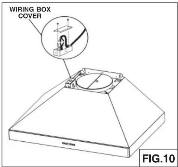
text_image
WIRING BOX COVER FIG.10ADDITIONAL EXTERNAL BLOWER WIRING (WPP9E)
- Run 2-wire plus ground power cable from the exterior blower to the hood's wiring box marked "motor connection" (Fig.11).
- Remove the cover from the wiring box and remove one knockout.
- Feed 6" of cable through the knockout opening and secure the cable to the wiring box with an appropriate connector.
- Make electrical connections at the hood. Connect white-to-white, red-to-black and green-to-ground.
- Replace the wiring box cover and screws. Make sure wires are not pinched between the cover and box.
Exterior blower connection:
- Make electrical connections at the exterior blower (see instructions provided with the exterior blower).
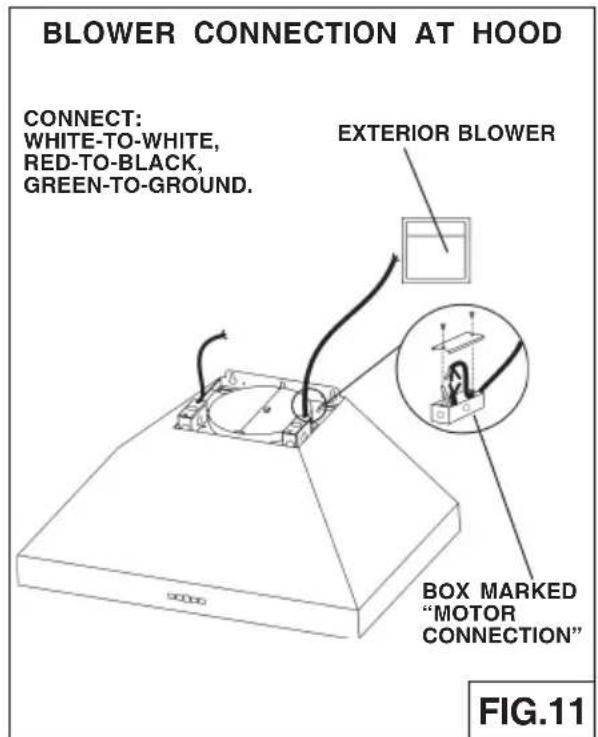
text_image
BLOWER CONNECTION AT HOOD CONNECT: WHITE-TO-WHITE, RED-TO-BLACK, GREEN-TO-GROUND. EXTERIOR BLOWER BOX MARKED "MOTOR CONNECTION" FIG.11INSTALL FLUE MOUNTING BRACKET
DUCTED AND NON-DUCTED
- Assemble the flue mounting bracket, adjusting outside width as shown. (Fig.12)
- Carefully center the mounting bracket directly over the range hood location.
- Secure the bracket assembly to the ceiling using (2) 4.8 x 38mm mounting screws and drywall anchors (Fig.13). Make sure the bracket is pushed into the corner, tight against the wall if necessary, and centered over the hood. Complete the installation.
DUCTED INSTALLATION ONLY
Note: Rooms with 10 or 11 foot ceilings require flue extension model AEWPP9SB, available from your local dealer. Discard the upper flue supplied with the range hood and replace it with the longer flue extension.
- Attach ductwork to damper/duct connector.
- Run 8" WPPIQ or 10" WPPIQT & WPPE diameter metal ductwork to the outside location (Fig.14).
- Install an appropriate wall or roof cap with damper to exhaust the air to the outside.
- Tape all duct joints with aluminum duct tape.
- Install upper and lower decorative flues onto the range hood. Vents are concealed on 8-foot ceilings. Vents maybe exposed on 9-foot ceilings (Fig.15).
- Secure upper flue to flue mounting bracket with (2) 3.9 x 6mm screws (Fig.16).
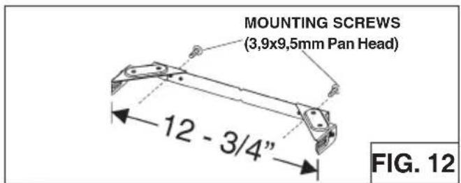
text_image
MOUNTING SCREWS (3,9x9,5mm Pan Head) 12 - 3/4" FIG. 12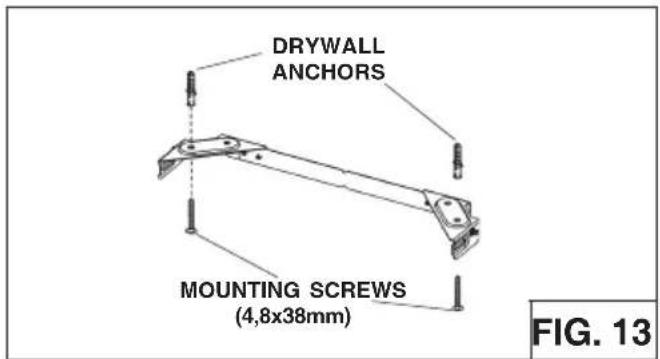
text_image
DRYWALL ANCHORS MOUNTING SCREWS (4,8x38mm) FIG. 13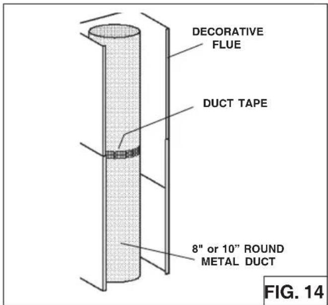
text_image
DECORATIVE FLUE DUCT TAPE 8" or 10" ROUND METAL DUCT FIG. 14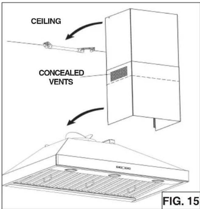
text_image
CEILING CONCEALED VENTS FIG. 15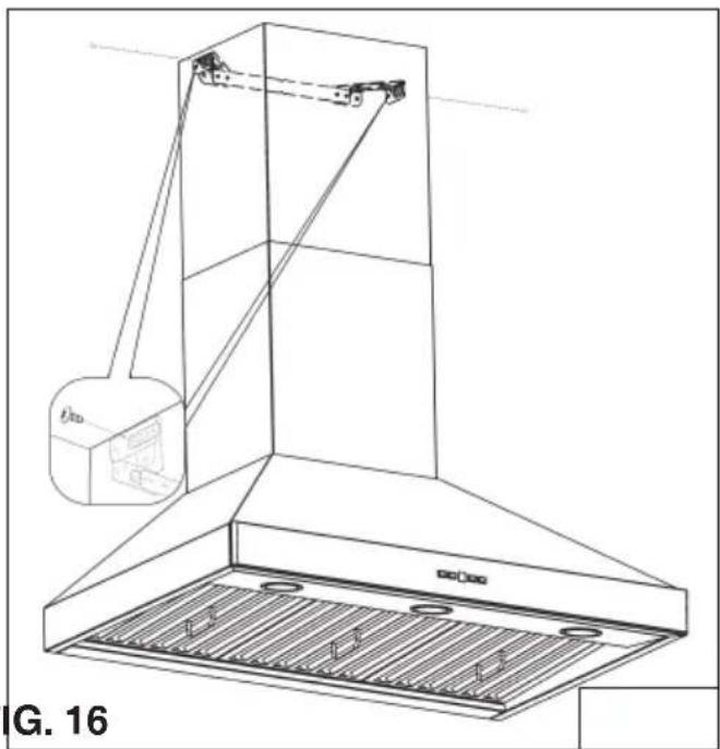
natural_image
Technical line drawing of a mechanical device with a labeled component (no text or symbols beyond label)NON-DUCTED INSTALLATION AVAILABLE ONLY FOR SINGLE BLOWER VERSION (WPP9IQ only)
Note:
a. Purchase Model ANKWPP9 Non-ducted Recirculation Kit from your local dealer.
b. Rooms with 10 or 11 foot ceilings require Flue Extension Model AEWPP9SBN, available from your local dealer. Discard the upper flue supplied with the range hood and replace it with the longer flue extension.
-
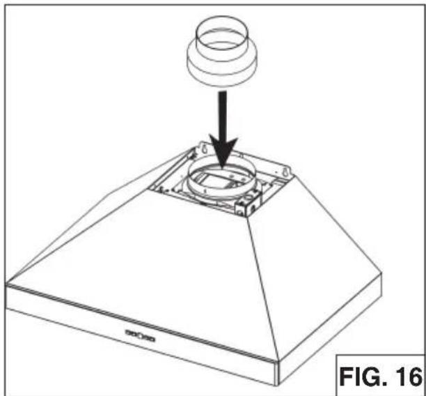
Attach the 6"-to-8" adapter to blower discharge and tape joint with aluminum duct tape (Fig.16).
-
Install the plenum to the upper decorative flue using (4) 3.9 x 6mm flat head screws provided as shown (Fig.17).
-
Attach 6" expandable ducting to the plenum using the adapter and tape joints with aluminum duct tape (Fig.18).
-
Slide upper flue into lower flue.
-
Attach flue assembly to hood.
-
Attach flex duct to plenum through the duct connector (Fig.18).
-
Attach upper flue to flue bracket using (2) 3.9 x 6mm flat head screws.
natural_image
Technical line drawing of a mechanical component with a cylindrical top and base, showing a downward arrow indicating assembly or adjustment (no text or symbols present)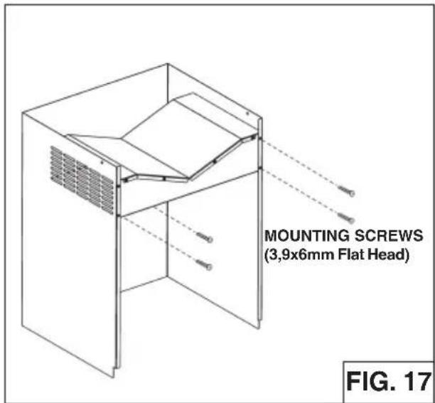
text_image
MOUNTING SCREWS (3,9x6mm Flat Head) FIG. 17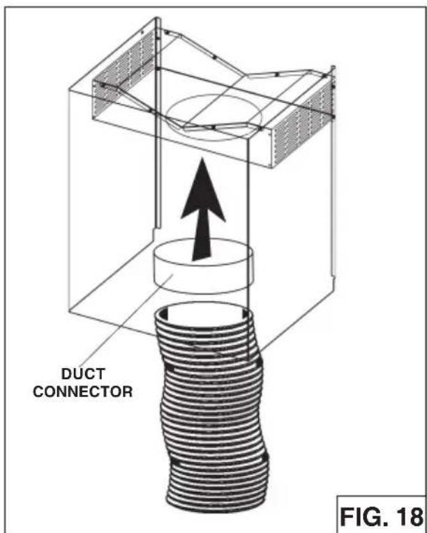
text_image
DUCT CONNECTOR FIG. 18DUCTED AND NON-DUCTED HOODS
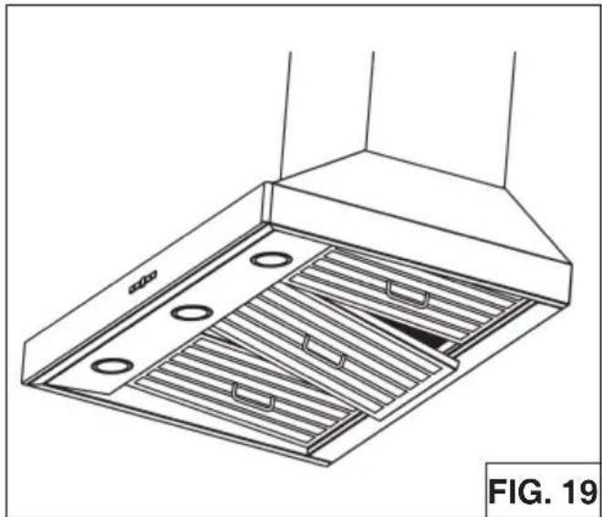
- To remove the GREASE filter, (Fig.19) push the filter towards the front so that it clears the filter channel, then pull down on the handle to disengage the filter from the hood. Tilt the filter downward and remove.
- The grease filters and the drip tray (see page 5 for removal & cleaning instructions) should be cleaned frequently. Use a warm detergent solution. Grease filters and the oil collectors are dishwasher safe.
- To install the GREASE filter, align rear filter tabs with spring in the hood. Pull down handle, push filter into position and release. Make sure the filter is securely engaged after installation.
NOTE: Prior to use, remove protective film from the filter frame.
natural_image
Technical line drawing of a kitchen ventilation duct with slatted base and ventilation slots (no text or symbols)NON-DUCTED HOODS (SINGLE MOTOR VERSION WPP9IQ only)
- Non-ducted recirculation filters not included. They must be purchased separately (ANKWPP9 Kit).
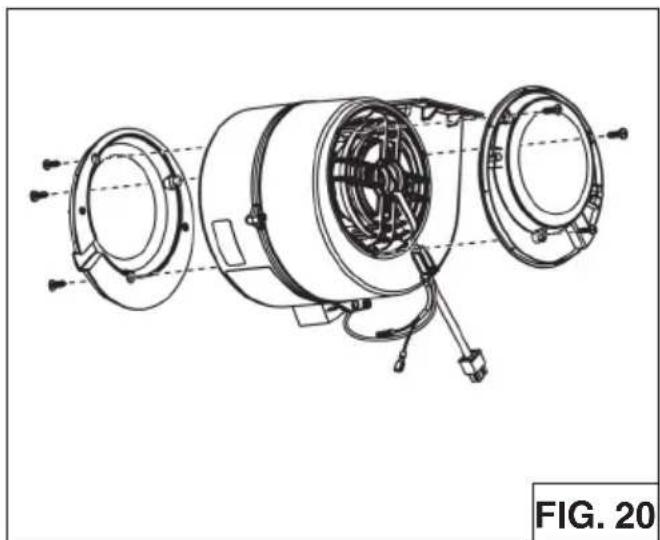
- Using no.6 x 1/2" screws, install one filter support on each side (provided) of the internal blower (Fig.20).
- Position each filter over its support, insert both pins (B) into the round slot (C) on filter side and rotate to lock in place (Fig.21).
Non-ducted recirculation filters
The non-ducted recirculation filters should be changed every 6 months. Rotate the filters to remove and replace.
natural_image
Technical line drawing of a mechanical assembly with multiple circular components and wiring (no text or symbols)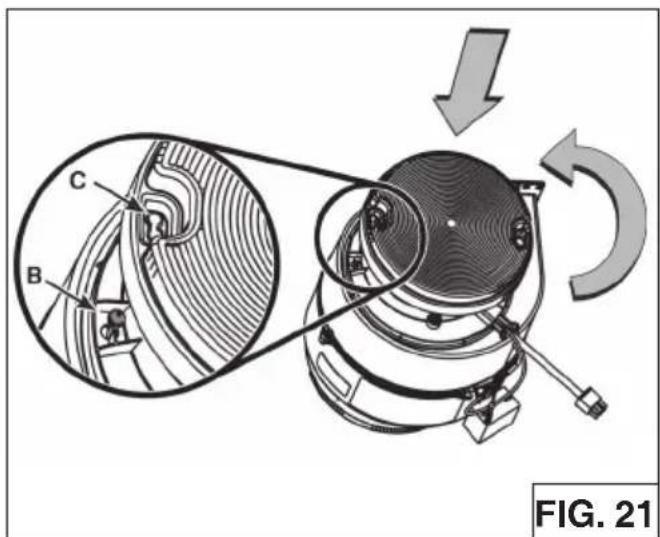
natural_image
Mechanical assembly diagram showing a belt drive system with labeled components (A, B, C) and motion arrows, no readable text or symbols beyond labels.CALIBRATE IQ BLOWER SYSTEM™ Ducted Internal Blower Hoods Only
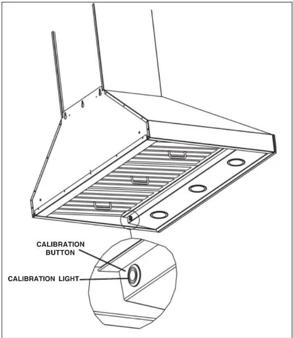
After the hood is installed and wired, engage the calibration process (our Guaranteed Performance System Technology) to ensure full-rated airflow is being delivered. Prior to calibration, ensure that all filters, light bulbs and duct system components are installed and sealed.
CALIBRATION PROCESS
Hold the calibration button for 3 seconds; calibration button will light up and stay on for up to 13 minutes. The blower will start and begin the calibration process. When calibration is complete, one of two things will occur:
A. The blower turns off and calibration button light turns off = Successful calibration.
B. The blower turns off and calibration button light blinks continuously = Too much restriction in the ductwork is preventing the IQ Blower System™ from achieving the rated airflow. The blower is automatically set to maximum intensity.
Note: Common items that cause restrictions: restricted damper flap (backdraft damper, wall cap, roof cap), too many elbows, duct size less than 80% of hood outlet, poor transition, use of flex ducting and/or crushed ducting.
Two options are available:
- Press the calibration button to accept airflow as is. The IQ Blower System ^TM is now configured to its highest possible setting. The blinking calibration light goes out.
- Correct duct restriction and repeat the calibration process.
a. To clear the original calibration data, hold calibration button for 10 seconds. The light will blink 3 times to confirm and the blower configuration will go back to default settings.
b. Repeat calibration process.
text_image
CALIBRATION BUTTON CALIBRATION LIGHTWPP9E Programming Mode Procedure
The range hood is designed to work with several different blowers models. Before using the hood, the control must first be programmed to your blower model, in order to achieve proper operating speed:
- Find the SETUP number that corresponds to the blower model that is installed with your range hood.
2.There must be power to the hood but the blower and lights must be turned off. - Push simultaneously LIGHT SWITCH and RESET SWITCH for 5 sec: the display shows a "P" blinking three times and then shows alternately the "P" and the setup selected.
-
Select the desired setup with BLOWER SWITCH (3→2→1) or RESET SWITCH (1→2→3).
-
Push TIMER SWITCH to confirm.
-
The display ("P") blinks two times (2 sec on - 0,5sec off) recording the selected setup.
| Description of “Speed Level” | SETUP 1 | SETUP 2 | SETUP 3 |
| Setup 1 is for motors with a rating up to 3.0 amp | EB6 | EB12 | EB9 |
| Setup 2 is for motors with a rating between 3.1 amp and 5.0 amp | ILB3 | EB15 | ILB11 |
| Setup 3 is for motors with a rating greater than 5.1 amp | ILB6 | ILB9 |
WARRANTY
ONE YEAR LIMITED WARRANTY FOR BEST PRODUCTS
Broan-NuTone LLC (Broan-NuTone) warrants to the original consumer purchaser of Best products that such products will be free from defects in materials or workmanship for a period of one year from the date of original purchase. THERE ARE NO OTHER WARRANTIES, EXPRESS OR IMPLIED, INCLUDING, BUT NOT LIMITED TO, IMPLIED WARRANTIES OR MERCHANTABILITY OR FITNESS FOR A PARTICULAR PURPOSE.
During this one-year period, Broan-NuTone will, at its option, repair or replace, without charge, any product or part which is found to be defective under normal use and service.
THIS WARRANTY DOES NOT EXTEND TO FLUORESCENT LAMP STARTERS, TUBES, HALOGEN AND INCANDESCENT BULBS, FUSE, FILTERS, DUCTS, ROOF CAPS, WALL CAPS AND OTHER ACCESSORIES FOR DUCTING. This warranty does not cover (a) normal maintenance and service or (b) any products or parts which have been subject to misuse, negligence, accident, improper maintenance or repair (other than by Broan-NuTone), faulty installation or installation contrary to recommended installation instructions.
The duration of any implied warranty is limited to the one-year period as specified for the express warranty. Some states do not allow limitation on how long an implied warranty lasts, so the above limitation may not apply to you.
BROAN-NUTONE'S OBLIGATION TO REPAIR OR REPLACE, AT BROAN-NUTONE'S OPTION, SHALL BE THE PURCHASER'S SOLE AND EXCLUSIVE REMEDY UNDER THIS WARRANTY. BROAN-NUTONE SHALL NOT BE LIABLE FOR INCIDENTAL, CONSEQUENTIAL OR SPECIAL DAMAGES ARISING OUT OF OR IN CONNECTION WITH PRODUCT USE OR PERFORMANCE. Some states do not allow the exclusion or limitation of incidental or consequential damages, so the above limitation or exclusion may not apply to you.
This warranty gives you specific legal rights, and you may also have other rights, which vary from state to state. This warranty supersedes all prior warranties.
To qualify for warranty service, you must (a) notify Broan-NuTone at the address stated below or telephone number stated below, (b) give the model number and part identification and (c) describe the nature of any defect in the product or part. At the time of requesting warranty service, you must present evidence of the original purchase date.
In USA - Best®, 926 W. State Street, Hartford, WI 53027 (800-558-1711)
In Canada - Best®, 550 Lemire Blvd., Drummondville, QC J2C 7W9 (866-737-7770)
www.BestRangeHoods.com
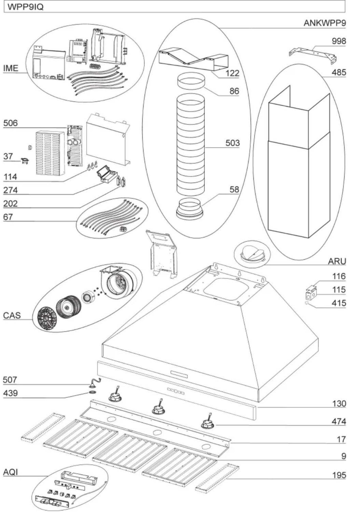
MODEL WPP9IQ
| KEY NO. | PART NO. | DESCRIPTION |
| 9 B08087951 | Grease Filters | |
| 17 BE3351882 | Light Diffuser Support 36” | |
| 17 BE3351898 | Light Diffuser Support 42” | |
| 37 B02300804 | Heat Sentry | |
| 67 B06102602 | Wires Assembly | |
| 114 B32904990 | Wire Clamp | |
| 115 BE3350233 | Wiring Box | |
| 116 BE3334252 | Wiring Box Cover | |
| 130 BE3405180 | Front trim 36” | |
| 130 BE3405184 | Front trim 42” | |
| 195 BE3351870 | Filter Spacers 42” only | |
| 202 B03292290 | Wire Clamp | |
| 274 B03295035 | Fuse Box | |
| 415 B03292596 | Fairlead | |
| 439 B02320034 | Grommet | |
| 474 B02300918 | Halogen Lamp | |
| 485 B08016372 | Decorative Flue Assembly | |
| 506 97019432 | BLDC Driver | |
| 507 B06102584 | Calibration Button Assembly | |
| * B080810995 | Fitting Set (Includes Key No. 998) | |
| AQI B06102596 | Switch Box Assembly | |
| ARU B08092501 | Duct Connector Assembly 8” | |
| IME B06145225 | Electrical Installation Assembly | |
| CAS B06002259 | Blower Assembly | |
| ANKWPP9 | B08999177 Non-Ducted Kit (Includes Key No. 58, 86, 122, 503) | |
| 58 B03294170 | Outlet Reduction | |
| 86 B03292300 | Outlet Flange | |
| 122 B08093448 | Riser | |
| 503 B02011557 | Expandable Duct | |
| AFCROUND2 | 99111455 Non-Duct Filter Supports | |
* Not shown assembled.
text_image
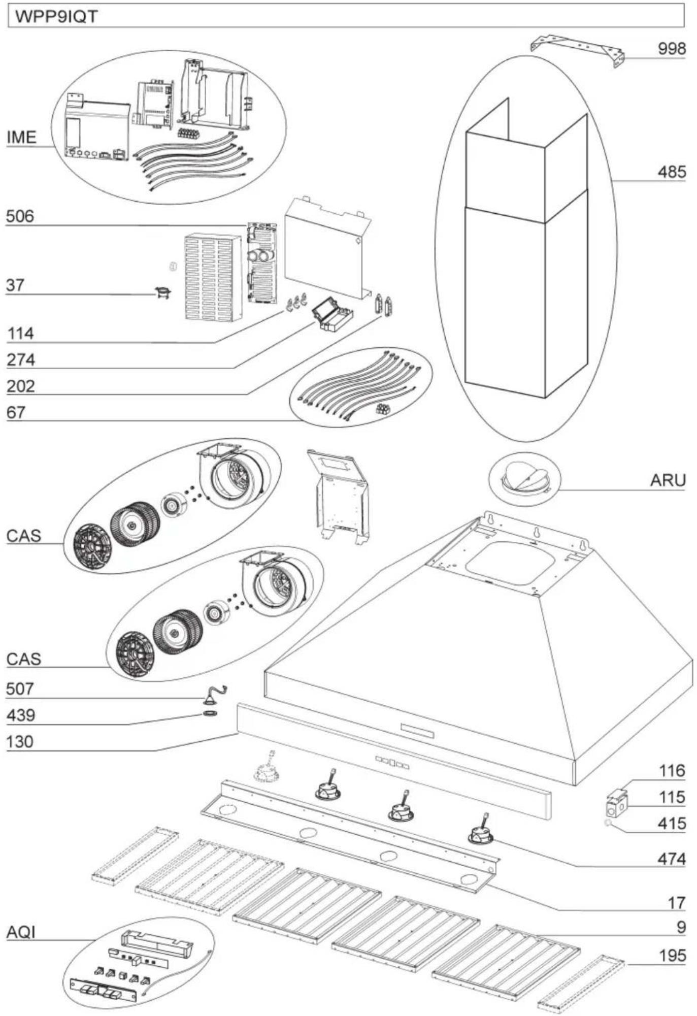
WPP9IQ IME 506 37 114 274 202 67 CAS 507 439 AQI ANKWPP9 998 485 122 86 503 58 ARU 116 115 415 130 474 17 9 195MODEL WPP9IQT
| KEY NO. | PART NO. | DESCRIPTION |
| 9 B08087951 | Grease Filters | |
| 17 BE3351882 | Light Diffuser Support 36" | |
| 17 BE3351898 | Light Diffuser Support 42" | |
| 17 BE3351906 | Light Diffuser Support 48" | |
| 17 BE3351915 | Light Diffuser Support 54" | |
| 37 B02300804 | Heat Sentry | |
| 67 B06102603 | Wires Assembly 36" or 42" | |
| 67 B06102606 | Wires Assembly 48" or 54" | |
| 114 B32904990 | Wire Clamp | |
| 115 BE3350233 | Wiring Box | |
| 116 BE3334252 | Wiring Box Cover | |
| 130 BE3405180 | Front trim 36" | |
| 130 BE3405184 | Front trim 42" | |
| 130 BE3405187 | Front trim 48" | |
| 130 BE3405190 | Front trim 54" | |
| 195 BE3351870 | Filter Spacers 42" and 54" only | |
| 202 B03292290 | Wire Clamp | |
| 274 B03295035 | Fuse Box | |
| 415 B03292596 | Fairlead | |
| 439 B02320034 | Grommet | |
| 474 B02300918 | Halogen Lamp | |
| 485 B08016379 | Decorative Flue Assembly | |
| 506 97019434 | BLDC Driver | |
| 507 B06102584 | Calibration Button Assembly | |
| * B080810995 | Fitting Set (Includes Key No. 998) | |
| AQI B06102596 | Switch Box Assembly | |
| ARU BE3405192 | Duct Connector Assembly 10" | |
| IME B06145225 | Electrical Installation Assembly | |
| CAS B06002259 | Blower Assembly |
* Not shown assembled.
text_image
WPP9IQT IME 506 37 114 274 202 67 ARU 485 998 CAS 116 115 415 474 17 9 AQI 195MODEL WPP9E
| KEY NO. | PART NO. | DESCRIPTION |
| 9 B08 | 087951 Grease Filters | |
| 17 BE3 | 351882 Light Diffuser Support 36" | |
| 17 BE3 | 351898 Light Diffuser Support 42" | |
| 17 BE3 | 351906 Light Diffuser Support 48" | |
| 17 BE3 | 351915 Light Diffuser Support 54" | |
| 37 B02 | 300804 Heat Sentry | |
| 67 B06 | 102604 Wires Assembly 36" or 42" | |
| 67 B06 | 102614 Wires Assembly 48" or 54" | |
| 114 B32 | 904990 Runner Wires | |
| 115 BE3 | 350233 Wiring Box | |
| 116 BE3 | 334252 Wiring Box Cover | |
| 130 BE3 | 405180 Front trim 36" | |
| 130 BE3 | 405184 Front trim 42" | |
| 130 BE3 | 405187 Front trim 48" | |
| 130 BE3 | 405190 Front trim 54" | |
| 195 BE3 | 351870 Filter Spacers 42" and 54" only | |
| 202 B03 | 292290 Wire Clamp | |
| 274 B03 | 295035 Fuse Box | |
| 415 B03 | 292596 Fairlead | |
| 474 B02 | 300918 Halogen Lamp | |
| 485 B08 | 016379 Decorative Flue Assembly | |
| * B08 | 0810995 Fitting Set (Includes Key No. 998) | |
| AQI B06 | 102596 Switch Box Assembly | |
| ARU BE3 | 405192 Duct Connector Assembly 10" | |
| IME B06 | 145226 Electrical Installation Assembly |
* Not shown assembled.
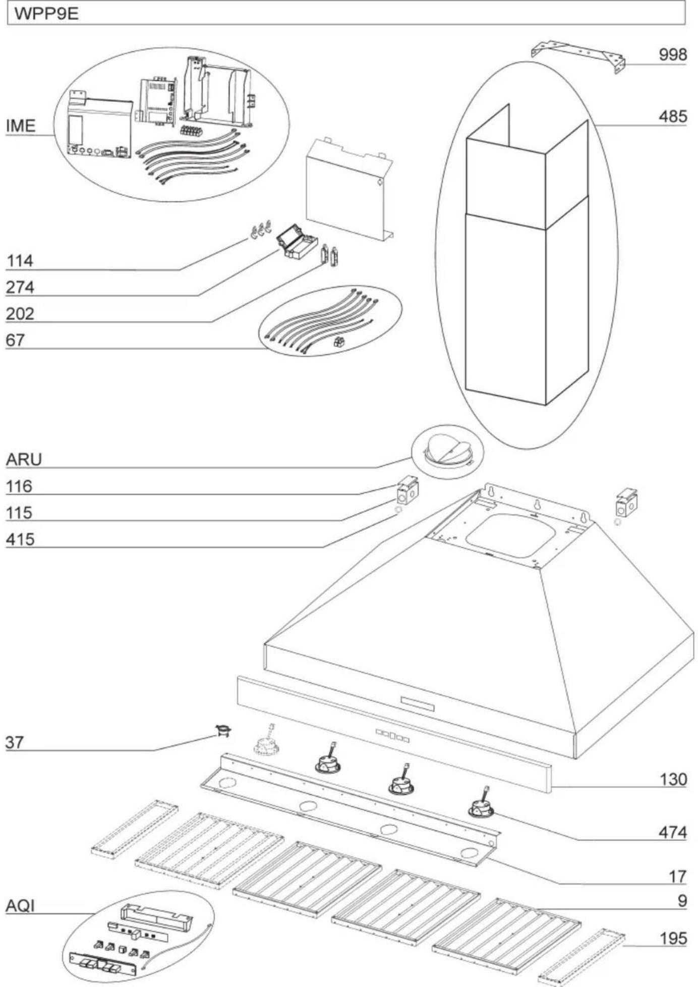
text_image
WPP9E IME 114 274 202 67 ARU 116 115 415 37 AQI 998 485 130 474 17 9 195best®
natural_image
Line drawing of a 3D isometric kitchen chimney (no text or symbols)Modèle WPP9
ENGLISH....3
FRANÇAIS......25
ESPAÑOL......49
Au CANADA - BEST Drummondville, QC, Canada
ENREGISTREZ VOTRE PRODUIT EN LIGNE À : www.BestRangeHoods.com/register
Pour de plus amples informations, visitez www.BestRangeHoods.com

CONÇUE POUR LES CUISINES PRIVÉES UNIQUEMENT


AVERTISSEMENTS
POUR RÉDUIRE LES RISQUES D'INCENDIE, D'ÉLECTROCUTION OU DE BLESSURES PHYSIQUES, RESPECTEZ LES INSTRUCTIONS CI-DESSOU:
natural_image
Technical diagram showing a ceiling fixture with internal components and directional arrows indicating motion or force (no text or symbols)flowchart
graph TD
    A["A"] --> B["B"]
    B --> C["C"]
    C --> D["D"]
    D --> R["R"]
natural_image
Technical diagram of a ceiling structure with an inset magnified view showing a circular component (no text or symbols)PRÉPARATION DE LA HOTTE
natural_image
Simple line drawing of a three-tiered rectangular box (no text or symbols)CARNEAU DÉCORATIF
2 ANCRAGES POUR
CLOISON SÈCHE
natural_image
Technical line drawing of two metal bracket components with mounting holes (no text or symbols)SUPPORT DE MONTAGE DU CARNEAU
INSTALLATION DU SYSTEME D'EVACUATION WPP9E Series
text_image
R 1/8" 5/8" R 3/8" Ø 3/8" 1-7/8" 36" - 15-1/8" 42" - 18-1/8" 48" - 21-5/8" 54" - 23-5/8" 12 - 7/8" FIG. 9INSTALLATION ELECTRIQUE (WPP9IQ et WPP9IQT)
natural_image
Technical line drawing of a mechanical device with a chimney and control panel (no text or symbols)INSTALLATION HOTTE NON CANALISÉE UNIQUEMENT DISPONIBLE POUR LE SINGLE VERSION (WPP9IQ seulement)
Remarque:
natural_image
Technical line drawing of a mechanical component with a cylindrical top and base, showing a downward arrow indicating assembly or adjustment (no text or symbols present)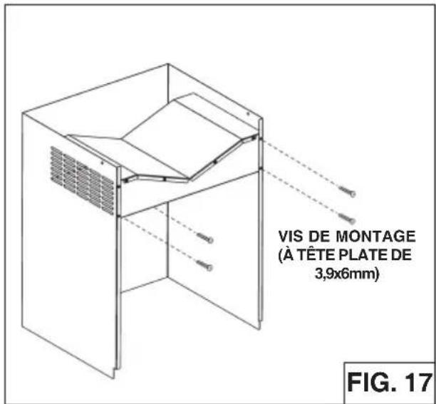
text_image
VIS DE MONTAGE (À TÊTE PLATE DE 3,9x6mm) FIG. 17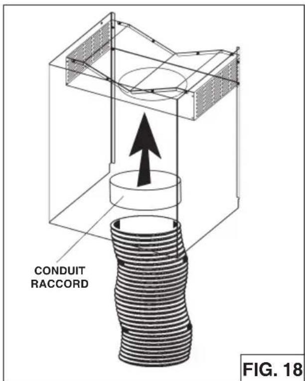
text_image
CONDUIT RACCORD FIG. 18INSTALLATION DES FILTRESS
HOTTES CANALISÉE ET NON CANALISÉE
natural_image
Technical line drawing of a kitchen ventilation duct with ventilation grilles and mounting holes (no text or symbols)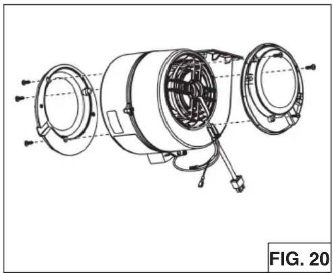
natural_image
Technical line drawing of a mechanical assembly with multiple circular components and wiring (no text or symbols)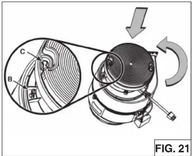
text_image
C B FIG. 21| SETUP 1 | SETUP 2 | SETUP 3 | |
| EB6 | EB12 | EB9 | |
| p | ILB3 | EB15 | ILB11 |
| ILB6 | ILB9 | ||
GARANTIE
GARANTIE LIMITÉE DE UN AN DE BEST
In USA - Best®, 926 W. State Street, Hartford, WI 53027 (800-558-1711)
In Canada - Best®, 550 Lemire Blvd., Drummondville, QC J2C 7W9 (866-737-7770)
www.BestRangeHoods.com
MODÈLE WPP9IQ
natural_image
Line drawing of a 3D isometric kitchen chimney (no text or symbols)Modelo WPP9
ENGLISH....3
FRANÇAIS......25
ESPAÑOL......49
REGISTRE SU PRODUCTO EN LÍNEA EN: www.BestRangeHoods.com/register
Para obtener información adicional visite www.BestRangeHoods.com
LEA Y CONSERVE ESTAS INSTRUCCIONES
PARA COCINAS DOMÉSTICAS SOLAMENTE
ADVERTENCIA
PARA REDUCIR EL RIESGO DE INCENDIOS, DESCARGAS ELÉCTRICAS O LESIONES PERSONALES, RESPETE LO SIGUIENTE:
natural_image
Technical diagram showing a mechanical assembly with arrows indicating motion or force direction (no text or symbols present)flowchart
graph TD
    A["A"] --> B["B"]
    B --> C["C"]
    C --> D["D"]
    D --> R["R"]
natural_image
Simple line drawing of a stacked rectangular box (no text or symbols)CHIMINEA DECORATIVA
2 ANCLAJES
natural_image
Technical line drawing of three metal bracket assemblies with mounting holes (no text or symbols)SOPORTE DE MONTAJE
text_image
R 1/8" 5/8" R 3/8" Ø 3/8" 1-7/8" 36" - 15-1/8" 42" - 18-1/8" 48" - 21-5/8" 54" - 23-5/8" 12 - 7/8"FIG. 9
CON DUCTO Y SIN DUCTO
natural_image
Technical line drawing of a mechanical device with a base plate and support structure (no text or symbols)natural_image
Technical line drawing of a mechanical component with a cylindrical top and base, showing a downward arrow indicating assembly or force (no text or symbols present)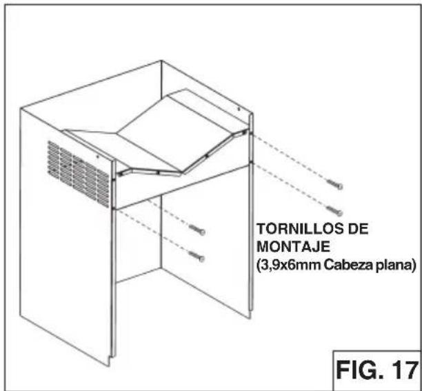
text_image
TORNILLOS DE MONTAJE (3,9x6mm Cabeza plana) FIG. 17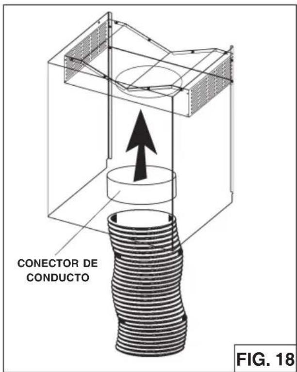
text_image
CONECTOR DE CONDUCTO FIG. 18CAMPANAS CON O SIN DUCTOS
natural_image
Technical line drawing of a kitchen ventilation duct with slatted base and ventilation slots (no text or symbols)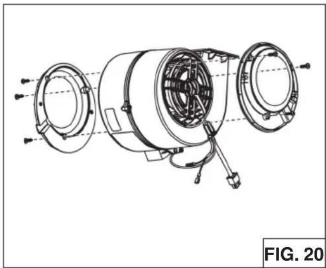
natural_image
Technical line drawing of a mechanical assembly with multiple circular components and wiring (no text or symbols)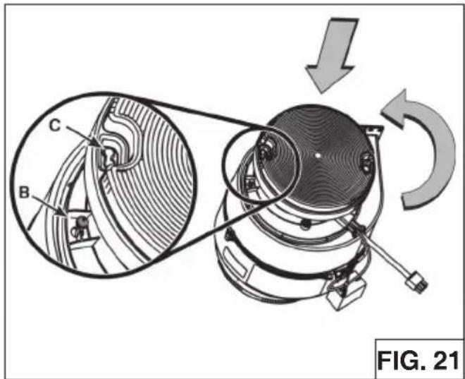
text_image
C B FIG. 21| SETUP 1 | SETUP 2 | SETUP 3 | |
| EB6 | EB12 | EB9 | |
| amp | ILB3 | EB15 | ILB11 |
| ILB6 | ILB9 | ||
GARANTIA
In USA - Best®, 926 W. State Street, Hartford, WI 53027 (800-558-1711)
In Canada - Best®, 550 Lemire Blvd., Drummondville, QC J2C 7W9 (866-737-7770)
www.BestRangeHoods.com