
NO534 - Receiver Mark Levinson - Free user manual and instructions
Find the device manual for free NO534 Mark Levinson in PDF.
| Product Type | Dual monaural amplifier (receiver) |
| Brand | Mark Levinson |
| Model | NO534 |
| Rated Output Power | 250 W RMS per channel into 8 ohms (20 Hz-20 kHz, <0.3% THD) |
| Frequency Response | 10 Hz - 20 kHz +0/-0.2 dB |
| Signal-to-Noise Ratio | 85 dB (ref. 2.83 V RMS) |
| Input Impedance | 60 kΩ (balanced), 30 kΩ (unbalanced) |
| Voltage Gain | 26 dB |
| Inputs | 2x XLR balanced, 2x RCA unbalanced |
| Speaker Outputs | 4 pairs of Hurricane binding posts (bi-wiring possible) |
| Control Connectors | Ethernet 10/100, RS-232 (RJ11), 12 V trigger input/output, USB-A, micro USB |
| Mains Voltage | 100 V, 120 V or 230 V AC (factory set), 1500 W max |
| Power Consumption (On) | 350 W (standby) |
| Power Consumption (Normal Standby) | 70 W |
| Power Consumption (Eco Standby) | 5 W |
| Power Consumption (Green Standby) | < 0.5 W |
| Dimensions (H x W x D) | With feet: 19.7 x 43.8 x 53.3 cm |
| Net Weight | 46.7 kg |
| Package Weight | 55.4 kg |
| Maintenance and Cleaning | Clean with a dry cloth; do not obstruct ventilation slots |
| Safety | Do not expose to water or moisture; use the supplied power cord; follow unpacking instructions (two persons required) |
| Spare Parts and Repairability | Contact an authorized Mark Levinson dealer or customer service (1 888 691-4171) |
| General Information | Class AB design, discrete circuitry, direct coupling, low-noise toroidal transformers |
Frequently Asked Questions - NO534 Mark Levinson
User questions about NO534 Mark Levinson
0 question about this device. Answer the ones you know or ask your own.
Ask a new question about this device
Download the instructions for your Receiver in PDF format for free! Find your manual NO534 - Mark Levinson and take your electronic device back in hand. On this page are published all the documents necessary for the use of your device. NO534 by Mark Levinson.
USER MANUAL NO534 Mark Levinson
Special Design Features 2
Installation Considerations 3
Safety Instructions, Unpacking, Placement and Ventilation, Power Requirements, Operating States
Getting Started 5
Front-Panel Overview, Rear-Panel Overview
Connections 9
Settings 12
Status LED, Internal Webpage, Software Update, ADVANCED: Settings Changes via USB
Troubleshooting 13
Specifications 14
Appendix 16
RS-232 Chart, Fault Conditions
ABOUT THIS DOCUMENT
This Owner's Manual covers unboxing of, familiarization with, and configuration of your amplifier. This manual will enable you to finely tailor the behavior and performance to fit your preferences and the particulars of your equipment and listening room. It is strongly recommended that you follow this manual in the order in which it is written so that you understand safety considerations before configuring this amplifier.
SPECIAL DESIGN FEATURES
Thank you for purchasing a N° 536 monaural or N° 534 dual-monaural amplifier. Since 1972, Mark Levinson® has been dedicated to the uncompromising art of sound, with the guiding principle of musical purity above all else. To achieve that goal like never before, Mark Levinson engineers scoured company archives, ultimately developing a proprietary, new, yet familiar amplifier design featuring outstandingly high current and tremendous open-loop linearity. The result is the Mark Levinson N° 536 monaural and N° 534 dual-monaural amplifiers. These fully discrete amplifiers drive virtually any loudspeaker effortlessly for impeccable imaging, musicality, and openness.
Philosophy
The pursuit of perfect amplification is a well-known theme in high-end audio. New technologies present new approaches, while looking to the past provides inspiration for the future. It was in that spirit that these amplifiers were developed: advised by the traditions and art of classic amplifier design, and infused with modern technology. A fully discrete, direct-coupled signal path; a highly linear, low-feedback design; and voltage gain and drive stages operating in class A, are joined by the modern system integration capabilities provided by Ethernet, RS-232, and USB for monitoring and network control.
Design Principles
Mark Levinson core design principles are its very high open-loop linearity and extremely high bias current. Because the amplifier circuitry was designed to have such intrinsically high performance, it requires very little feedback to achieve impeccably low distortion and enormously wide bandwidth. Employing unusually high bias current enables superb linearity with wide bandwidth: nearly immune to the effects of parasitic capacitances, these amplifiers are able to change voltage with unreserved agility. These design principles create the hallmarks of Mark Levinson amplification: effortlessness, openness, and unadulterated smoothness throughout the entire frequency range, regardless of load or listening level.
Components
Mark Levinson takes pride in both the art and science of engineering. To that end, components are selected based not only on their technical merits, but also on their sonic capabilities.
The N° 536 Monaural Amplifier contains 12 discrete 15A, 260V, 200W TO-264 bipolar output transistors per output stage (24 total); and 12 discrete 230V, 70MHz TO-220 bipolar driver transistors per output stage (one for each output transistor, 24 total). Its power supply contains eight discrete, high speed, 40A, 250V TO-220 Schottky rectifiers per output stage (16 total) and 18 filter capacitors per output stage (36 total) for a grand total of 169,200 microfarads of storage capacitance.
The N° 534 Dual-Monaural Amplifier contains 12 discrete 15A, 260V, 200W TO-264 bipolar output transistors per channel (24 total); and 12 discrete 230V, 70MHz TO-220 bipolar driver transistors per channel (one for each output transistor, 24 total). Its power supply contains eight discrete, high speed, 40A, 250V TO-220 Schottky rectifiers per channel (16 total) and 18 filter capacitors per channel (36 total) for a grand total of 118,800 microfarads of storage capacitance.
The amplifiers also feature custom-designed, low noise toroidal transformers, rated for 1,800VA and 1,900VA total continuous power, respectively, with separate secondary windings for each output stage. The output stage and power supply components are over-specified to offer unsurpassed performance and reliability. The input stages contain matched-pair, low-noise, high-gain, dual JFET input transistors, which in turn are connected in a double cascode configuration to bipolar transistors; the combination of devices offers inherently low distortion and wide bandwidth, as well as the ability to effortlessly swing large signal voltages. This circuit operates in class A and uses discrete TO-126 bipolar pre-driver transistors to accurately drive the massive output stages.
Features
• Class AB design rated at:
a. N° 536: 400W into 8 ohms and 800W into 4 ohms
b. N° 534: 250W per channel into 8 ohms and 500W per channel into 4 ohms
• Fully discrete signal path, input to output
- High linearity, low-feedback design for low distortion and wide bandwidth
• Voltage gain and driver stages operate in class A
- Direct coupled: no capacitors in the signal path
- Custom-designed, low-noise toroidal transformers
- High current linear power supplies employing low noise, high speed discrete Schottky rectifiers and multiple paralleled filter capacitors
• Mirror-image symmetrical design
- Four binding posts per channel with Hurricane terminals for standard and bi-wired loudspeaker connections
- System controls: Ethernet, RS-232, IR input, 12V trigger input and output, USB
INSTALLATION CONSIDERATIONS
SAFETY INSTRUCTIONS
- Read these instructions
- Keep these instructions
- Heed all warnings
- Follow all instructions
- Do not use this apparatus near water
-
Clean only with a dry cloth
-
Do not block any ventilation openings. Install in accordance with the manufacturer's instructions.
-
Do not install near any heat sources such as radiators, heat registers, stoves or other apparatus that produce heat.
-
Do not defeat the safety purpose of the polarized or grounding-type plug. A polarized plug has two blades with one wider than the other. A grounding-type plug has two blades and a third grounding prong. The wide blade or third prong is provided for your safety. If the provided plug does not fit into your outlet, consult an electrician for replacement of the obsolete outlet.
-
Protect the power cord from being walked on or pinched, particularly at plugs, convenience receptacles and the point where it exits from the apparatus.
-
Only use attachments and accessories specified by the manufacturer.
-
Use only with the cart, stand, tripod, bracket or table specified by the manufacturer or sold with the apparatus. When a cart is used, use caution when moving the cart/ apparatus combination to avoid injury or tip over.
-
Unplug this apparatus during lightning storms or when unused for long periods of time.
-
Refer all servicing to qualified service personnel. Servicing is required when the apparatus has been damaged in any way, such as when the power-supply cord or plug is damaged; liquid has been spilled or objects have fallen into the apparatus; or the apparatus has been exposed to rain or moisture, does not operate normally or has been dropped.
-
The MAINS cord is intended to be the safety disconnect device for this apparatus and shall remain readily operable at all times.
-
Ventilation should not be impeded by covering the ventilation openings with items such as newspapers, tablecloths, or curtains.
-
No naked flame sources, such as candles, should be placed on the apparatus.
-
Terminals marked with this symbol may be considered HAZARDOUS
LIVE, and the external wiring connected to these terminals requires installation by an INSTRUCTED PERSON or the use of ready-made leads or cords.

- This product must be terminated with a three-conductor AC mains power cord that includes an earth ground connection. To prevent shock hazard, all three connections must ALWAYS be used.
WARNING! To reduce the risk of fire or electric shock, do not expose this apparatus to rain or moisture. The apparatus shall not be exposed to dripping or splashing. No objects filled with liquids, such as vases, shall be placed on the apparatus.
SAFETY TERMS & SYMBOLS
These terms may appear in this manual:
Warning! Calls attention to a procedure, practice, condition or the like that, if not correctly performed or adhered to, could result in personal injury or death.
Caution! Calls attention to a procedure, practice, condition or the like that, if not correctly performed or adhered to, could result in damage or destruction to part or all of the component.
Note Calls attention to information that is essential to highlight.
These symbols may appear on the product:
Appears on the component to indicate the presence of

noninsulated, dangerous voltage inside the enclosure - voltage that may be sufficient to constitute a risk of shock.

Appears on the component to indicate important operation and maintenance instructions included in the accompanying documentation.
UNPACKING
When unpacking your amplifier:
- Save all packing materials in case you need to ship your amplifier in the future.
- Inspect your amplifier for signs of damage during shipment. If you discover damage, contact your authorized Mark Levinson dealer for assistance in making appropriate claims.
- Please register your amplifier within 15 days of purchase at marklevinson.com.
- Retain your original, dated sales receipt as proof of warranty coverage.
- Remove the accessory box from the shipping carton. Make sure that all of the items listed below are included. If any are missing, contact your authorized Mark Levinson dealer.
o IEC power cord (terminated according to the region to which the unit is shipped)
o Pair of gloves (for use during unpacking and setup)
o Documentation
CAUTION!: DO NOT attempt to lift or move the power amplifier without adequate assistance. The shipping weight of the amplifier exceeds what a single person should lift alone. To avoid injury or damage to the unit, at least two people are required to lift or move the amplifier.
Knit gloves with special gripping surfaces on the palms and fingers are included with the amplifier. Wear these gloves when lifting or moving the amplifier.
A heavy strap is routed underneath the amplifier and up through the heat sink fins, allowing two people to more easily lift the amplifier out of the shipping carton.
PLACEMENT AND VENTILATION
- DO install the power amplifier on its own shelf for proper ventilation.
- DO install the amplifier chassis on a solid, flat, level surface.
- DO install the power amplifier close to associated components to keep interconnecting cables as short as possible.
- DO select a dry, well-ventilated location out of direct sunlight.
- DO allow at least 3 to 4 inches (8 to 10cm) of clearance above and on each side of the amplifier for proper heat dissipation.
- DO allow at least 6 inches (15cm) of clearance behind the amplifier so that the power cord and cables have space to bend without becoming crimped or strained.
- DO NOT place the amplifier chassis on a thick rug or carpet or cover the amplifier with a cloth, as this might prevent proper cooling.
- DO NOT obstruct the ventilation holes on the top and bottom of the chassis or reduce airflow through the amplifier.
- DO NOT place the amplifier chassis near low-level components. The power amplifier is capable of producing large output currents and hence significant magnetic fields, which can induce noise in sensitive components.
- DO NOT expose the power amplifier to high temperatures, humidity, steam, smoke, dampness, or excessive dust. Avoid installing near radiators and other heat-producing appliances.
POWER REQUIREMENTS
The amplifier is configured at the factory for 100, 115, or 230 VAC power operation at 50Hz or 60Hz. Before operating, ensure that the power label on the rear panel near the AC input connector indicates the correct operating voltage. A detachable IEC power cable intended for use in the region where the unit is sold is included. Connection to an AC voltage other than that for which the unit is intended can create a safety and fire hazard and may damage the unit. If you have any questions about the voltage requirements for your amplifier or about the line voltage in your area, contact your authorized Mark Levinson dealer before plugging the unit into an AC power outlet.
WARNING! MAKE SURE all components in the audio system are properly grounded. Do NOT defeat the safety purpose of polarized or grounding-type plugs with "ground-lifter" or "cheater" adapters. Doing so may cause dangerous voltage to build up between components, which may result in personal injuries and/or product damage.
You should unplug the amplifier from the AC wall outlet during lightning storms and extended periods of non-use.
CAUTION: BEFORE moving the unit, make sure it is powered off by removing the power cord from the AC power outlet and the unit's rear panel.
OPERATING STATES
The amplifier has three operating states:
- Off: The AC mains power is disconnected by using the rear-panel Power switch or by removing the power cord from the rear panel.
- Standby: The Standby mode can be configured to one of three types: Green, Power Save, and Normal.
o Green: This mode removes power from almost all of the circuits, allowing the unit to be activated only via a 5V – 12V trigger or a press of the Standby button. This mode provides maximum power conservation and is the factory-default Standby mode. In this mode, the LED is dimmed.
Power Save: This mode removes power from the audio circuits, but keeps the control circuitry powered and ready to receive commands. This mode provides moderate power conservation. In this mode, the LED is dimmed.
Normal: This mode mutes the audio outputs, but keeps all of its control and audio circuits powered. This mode provides the least amount of power conservation but allows the audio circuits to remain warmed up to deliver optimal performance at all times.
- On: The entire unit is powered up and all outputs are active. The front panel LED illuminates red steadily when the unit is on.
When Green or Power Save are selected, the amplifier also engages its Auto Off function that automatically places it into Standby after 20 minutes of no audio signal or control input. You can bypass Auto Off by selecting Normal standby or supplying 12V DC to the Trigger Input from a preamplifier or other component in the system. For more information on changing settings of the amplifier, please see the Settings section of this manual.
GETTING STARTED
FRONT PANEL
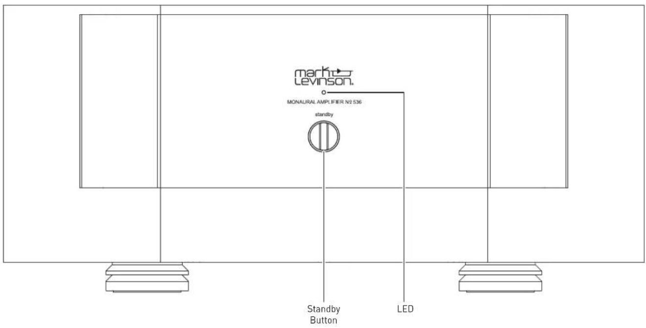
Standby button: press this button to put the unit into and out of the selected Standby mode.
LED: illuminates red when the unit is On, and flashes slowly when the unit is in Standby mode. Illuminates blue when loading software. Illuminates white during fault conditions.
REAR PANEL
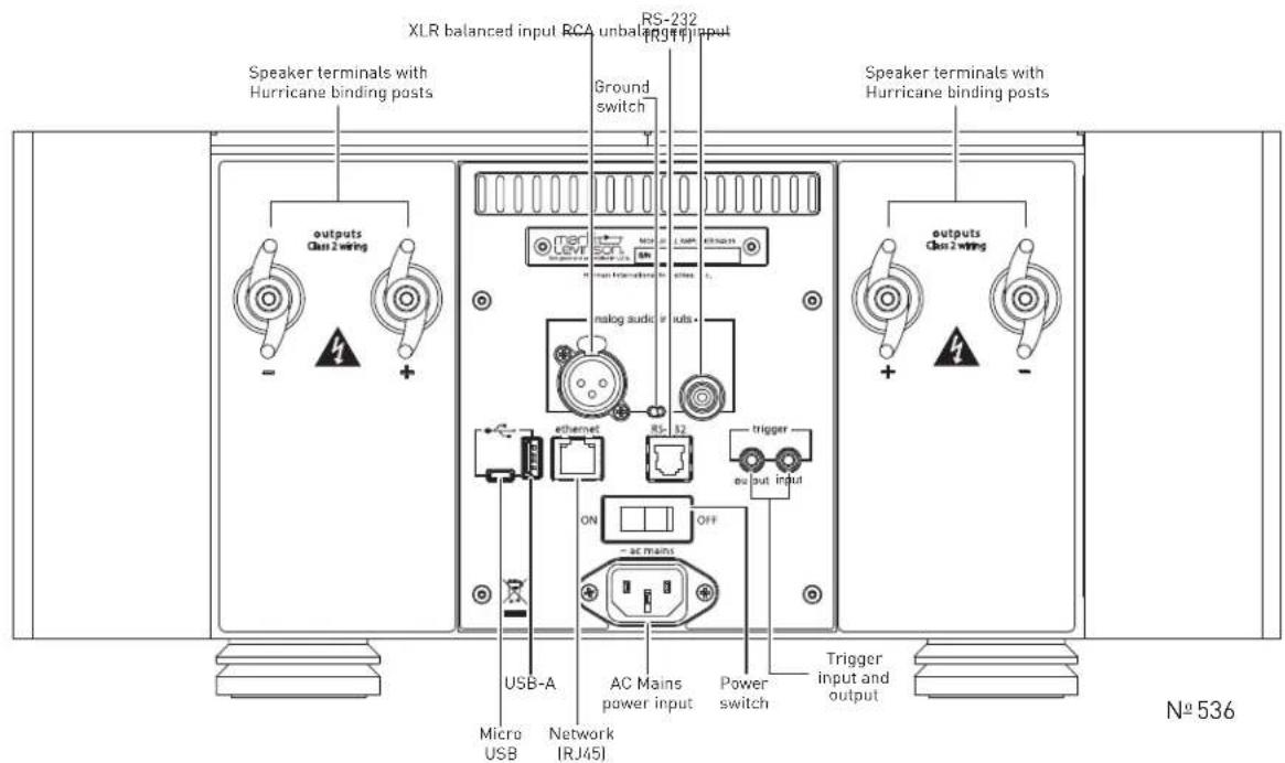
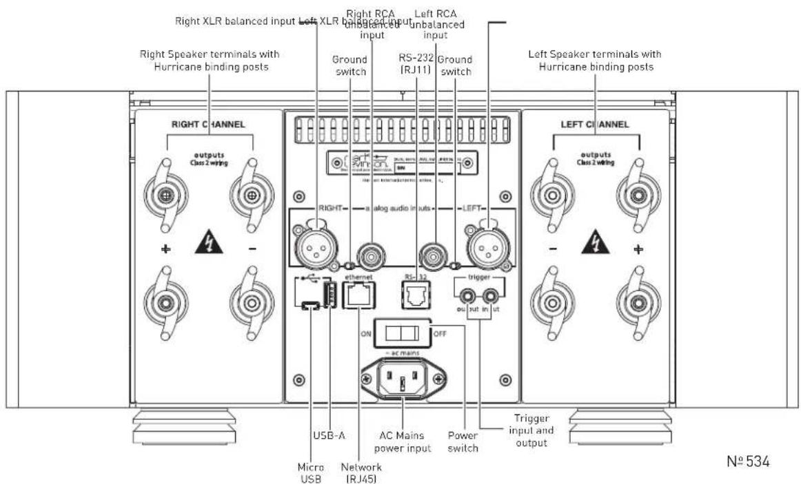
Input Connectors
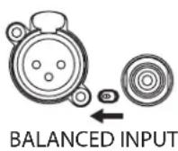
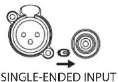
One balanced and one single-ended (unbalanced) connector is available for each audio channel input.
Ground switch: A small toggle switch selects the grounding appropriate for either the balanced (XLR) or single-ended (RCA) input connector(s). Make sure the toggle switch is set all the way to the position closest to the connector you are using. The switch does not select the connectors; it only changes the grounding to suit the selected connector.
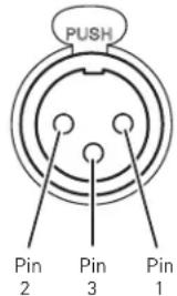
Balanced analog input connectors: these connectors accept left-channel and right-channel balanced input signals from a line preamplifier or other source with balanced (male XLR) output connectors.
Balanced connector pin assignments:
- Pin 1: Signal ground
• Pin 2: Signal + (non-inverting) "hot" - Pin 3: Signal – (inverting) "cold"
Balanced Input Connector (female XLR)
Single-ended input connectors: these connectors accept left-channel and right-channel single-ended (unbalanced) input signals from a line preamplifier or other source without balanced output connectors. Mark Levinson recommends using balanced connections whenever possible.
Output Connectors
Binding Posts: The amplifiers utilize custom-made, gold-plated, high-current loudspeaker binding posts. The positive binding posts, labeled + (positive), are red; the negative binding posts are black and are labeled - (negative).
Two of each binding post are present on each channel. For most setups, connect one of the positive and one of the negative terminals per channel to the respective loudspeaker terminals.
The additional binding posts enable optional bi-wiring for compatible loudspeakers. If your loudspeakers support bi-wiring, connect both red (positive) terminals to the red terminals on the loudspeaker, and connect both black (negative) terminals to the black terminals on the loudspeaker.
If your loudspeakers do not support bi-wiring or you prefer not to employ this connection configuration, simply connect one of the positive and one of the negative terminals to the respective loudspeaker terminals. There is no additional configuration needed to disable bi-wiring output capability.
Banana plugs can also be used to connect the speaker cables to the loudspeaker binding posts. The banana plug connections are covered on European models due to safety regulations.
NOTE: Ensure when connecting the loudspeaker that at least one positive and one negative binding post is used.
Caution!
Be careful to not short the positive and negative outputs together. Do not short the positive or negative outputs to chassis or any other safety ground. The amplifier must be powered off during installation and whenever input and/or output cables are being connected.
Caution!
DO NOT OVERTIGHTEN the binding posts. The innovative design of these binding posts provides more leverage; hence, high-contact, tight pressure connections are achieved when finger-tightened.
DO NOT FORCE the binding post "wings" over a bent or oversized connector. Doing so may damage the binding post.
NOTE: The audio outputs of these power amplifiers are considered Class 2 (CL2) circuits in North America. This means the wire connected between this amplifier and the speaker(s) shall be rated at minimum Class 2 (CL2) and shall be installed according to the U.S. National Electrical Code (NEC) Article 725 or Canadian Electrical Code (CEC) Section 16.
Control Connectors
Micro USB connector: this connection enables the unit to be connected to a computer for internal webpage discovery. For more information on using the internal webpage, please see the Settings section of this manual.
USB Type-A connector: the connector is for attaching a USB drive containing software update, or for importing setup configurations. Further information on software updates is available from the Settings section of this manual.
Ethernet connector: This connector accepts a Cat5 or higher cable for connection to a home network. The Ethernet connection is a standard 10/100 connection for external control and networking. The amplifier supports connection to a router, network, or computer.
RS-232 connector: This RJ-11 connector provides serial control through a standard RS-232 connection. For a table of RS-232 commands please see the Appendix section of the manual.
Trigger output connector: This 1/8-inch (3.5mm) TS phone jack can be used to activate other components in the audio system and listening room, such as amplifiers, lights, and window shades. A 12V 100mA DC signal is output whenever the unit is on. (See illustration)
Trigger phone plug connector pin assignments:
- Tip: +
- Sleeve: -

Trigger input connector: this 1/8-inch (3.5mm) TS phone jack can be connected to the trigger output of another system component or control system that supplies a trigger voltage. Whenever the unit detects a voltage between 3V and 12V DC at this connection, it will turn On from Standby. When the trigger signal at this connection ceases, the unit will enter the selected
Standby mode. When the Trigger Input is used to turn the amplifier on, the Auto Off functionality is disabled.
AC Mains connector: This connector provides AC power to the unit when the supplied power cord is connected from it to an AC electrical outlet. Unplug the amplifier from the AC wall outlet during lightning storms and extended periods of non-use.
Power switch: This mechanical switch turns the unit's power supply on or off. During normal operation, do not use the Power switch to power off the unit; instead, use the Standby button.
CONNECTIONS
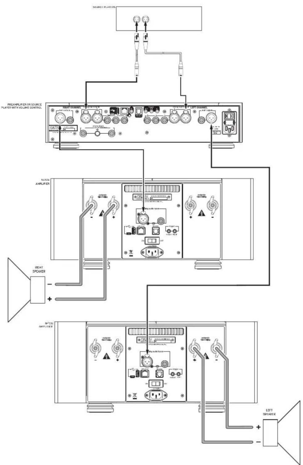
INITIAL CONNECTIONS
CAUTION: Before making connections, make sure the amplifier and all associated components are powered off and disconnected from electrical outlets.
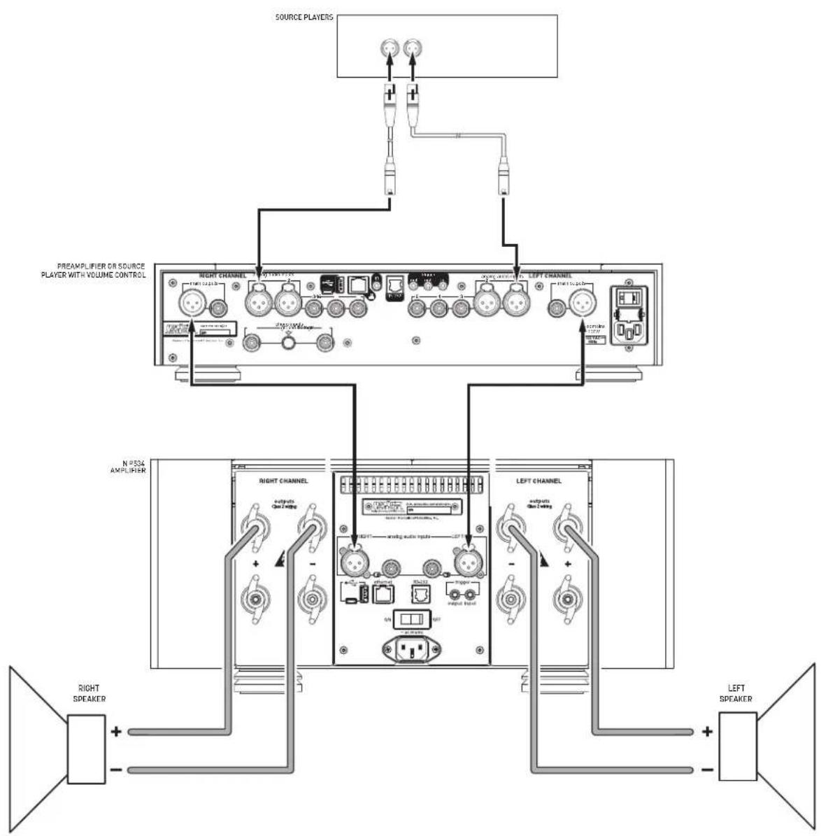
- Connect your preamplifier or source device with volume control to either the amplifier's Balanced (XLR) or Single Ended (RCA) input connectors. Mark Levinson recommends using the Balanced input connectors if your preamplifier or source equipment has balanced output connectors.
- Switch the Ground Switch(es) to the position closest to the inputs you have connected. Check that the switch is all the way to the end of its travel path.
- Connect speaker cables to the binding posts of the amplifier(s) and loudspeakers.
- Connect the supplied power cable to the amplifier's AC Mains connector and into an electrical outlet. Turn the rear-panel Power switch on the amplifier to On, and turn on all associated components.
- Press the front-panel Standby button on each component in the system.
- Start playback from the connected source and adjust the volume level slowly. It is best to start low and turn up to avoid unintentionally damaging your equipment. Begin playing the selected source device.
flowchart
graph TD
    A["Source Players"] --> B["PREAMPLIFIER OR SOURCE PLAYER WITH VOLUME CONTROL"]
    B --> C["RIGHT CHANNEL"]
    B --> D["LEFT CHANNEL"]
    C --> E["OUTPUT MODE"]
    D --> F["OUTPUT MODE"]
    E --> G["OUTPUT MODE"]
    F --> H["OUTPUT MODE"]
    G --> I["OUTPUT MODE"]
    H --> J["OUTPUT MODE"]
    I --> K["OUTPUT MODE"]
    J --> L["OUTPUT MODE"]
    K --> M["OUTPUT MODE"]
    L --> N["OUTPUT MODE"]
    M --> O["OUTPUT MODE"]
    N --> P["OUTPUT MODE"]
    O --> Q["OUTPUT MODE"]
    P --> R["OUTPUT MODE"]
    Q --> S["OUTPUT MODE"]
    R --> T["OUTPUT MODE"]
    S --> U["OUTPUT MODE"]
    T --> V["OUTPUT MODE"]
    U --> W["OUTPUT MODE"]
    V --> X["OUTPUT MODE"]
    W --> Y["OUTPUT MODE"]
    X --> Z["OUTPUT MODE"]
    Y --> AA["OUTPUT MODE"]
    Z --> AB["OUTPUT MODE"]
    AA --> AC["OUTPUT MODE"]
    AB --> AD["OUTPUT MODE"]
    AC --> AE["OUTPUT MODE"]
    AD --> AF["OUTPUT MODE"]
    AE --> AG["OUTPUT MODE"]
    AF --> AH["OUTPUT MODE"]
    AG --> AI["OUTPUT MODE"]
    AH --> AJ["OUTPUT MODE"]
    AI --> AK["OUTPUT MODE"]
    AJ --> AL["OUTPUT MODE"]
    AK --> AM["OUTPUT MODE"]
    AL --> AN["OUTPUT MODE"]
    AM --> AO["OUTPUT MODE"]
    AN --> AP["OUTPUT MODE"]
flowchart
graph TD
    A["Source Players"] --> B["Preamplifier OR SOURCE PLAYER WITH VOLUME CONTROL"]
    B --> C["Right Channel"]
    B --> D["Left Channel"]
    C --> E["N° 200A AMPLIFIER"]
    D --> F["N° 200A AMPLIFIER"]
    E --> G["Right Speaker"]
    F --> H["Right Speaker"]
    G --> I["N° 300 AMPLIFIER"]
    H --> J["N° 300 AMPLIFIER"]
    I --> K["Left Speaker"]
    J --> L["Left Speaker"]
SETTINGS
SELECTING STANDBY MODE
To select a Standby Mode, with the amplifier's power switched off using the rear-panel Power Switch, hold the front-panel Standby button and turn the Power Switch to On. Continue to hold the Standby button until the Status LED flashes rapidly. The amplifier is now in Standby Select Mode. Each subsequent press of the Standby Button selects the next Standby mode:
- Rapid red flash: Green mode
- Rapid blue flash: Power Save mode
- Rapid white flash: Normal mode
To exit Standby Select Mode, wait approximately ten seconds until the Standby LED stops rapidly flashing. The amplifier will enter Standby and save your selection. The Standby LED will flash red, slowly. The Standby Mode can also be changed by RS232 Command, the Internal Web Page or a setup.txt file.
INTERNAL WEBPAGE
To access the unit's internal webpage for the first time:
- You will need the following items:
o Micro USB cable (micro USB to USB type A) o Network cable (Cat5 or higher) - Connect the unit to a network via Ethernet, and connect and turn on power to the unit
- Ensure that the unit and computer are connected to the same network
• Take the unit out of Standby and wait for the unit to turn on. - Connect the unit to a computer using the micro USB connector.
- The unit will mount to the computer as a mass-storage device containing a file—SETUP.TXT—with unit information, and a hyperlink to its internal webpage
- Click the hyperlink. If the hyperlink does not seem to work try a different browser. The internal webpage provides options for selecting standby mode and unit status monitoring
SOFTWARE UPDATE
- You will need a brand-name USB flash drive (or "thumb drive," or "stick")
- Turn the unit's power off via the rear-panel switch
- Using a computer, download the unit software file from the appropriate product's page at marklevinson.com to the root folder of the USB drive
- Connect the USB drive to the unit and turn the power switch on
- The unit's LED will flash blue during update; when complete, it will switch to flashing red
ADVANCED: SETTINGS CHANGES VIA USB
You can change or load settings and configurations using the micro USB connector.
- You will need a micro USB cable (micro USB to USB type A)
- Turn the unit's power off via the rear-panel switch
- Connect the unit to a computer using the micro USB cable
- Turn on power: the unit will mount to the computer as a mass-storage device containing SETUP.TXT
- Open SETUP.TXT on your computer with a text editor application (not a word processor)
| # - | Description | (access) = | Option |
| 1 - | Device Name | (ReadOnly) = | MLNo536 |
| 2 - | Factory Default | (ReadWrite) = | No |
| 3 - | DebugZones | (ReadWrite) = | 00001000 |
| 4 - | Ethernet Ready | (ReadOnly) = | No |
| 5 - | DHCP (yes/no) | (ReadWrite) = | Yes |
| 6 - | IP address | (ReadOnly) = | 169.254.55.56 |
| 8 - | Network Mask | (ReadOnly) = | 255.255.255.0 |
| 9 - | Network Gateway | (ReadOnly) = | 255.255.255.0 |
| 10 - | MAC Address | (ReadWrite) = | 00:16:5a:00:02:a6 |
| 11 - | NETBIOS name | (ReadWrite) = | MLN0536X |
| 12 - | StandbyMode (G/P/N) | (ReadWrite) = | Normal |
| 13 - | TrigOut delay(sec) | (ReadWrite) = | 1 |
- The following items can be edited to load changes to the amplifier's settings:
o Item 2 – Restore Factory Defaults: Yes or No
o Item 5 – DHCP: Yes or No
o Item 11 - Unit Name: alphanumeric, no spaces
o Item 12 - Standby Mode: Normal, Green, or PWRSave
o Item 13 - Trigger Out Delay: 1-x seconds
- Save the file, turn the rear-panel power switch off and then on
Caution: Editing items in the SETUP.TXT file is intended for professional installers and could cause problems if incorrect settings are stored. Contact your dealer or Mark Levinson support if you are not sure how to make the change you are attempting.
TROUBLESHOOTING
Incorrect operation is sometimes mistaken for malfunction. If problems occur, see this section for troubleshooting information. If problems persist, contact your authorized Mark Levinson dealer.
NO POWER
Examine the power cord to ensure that it is connected to both the AC mains connector and a working, unswitched electrical outlet.
Make sure the amplifier is powered on with the rear-panel Power switch. Examine the electrical circuit breaker to ensure that power is being supplied to the electrical outlet to which the amplifier is connected.
Make sure the amplifier is not in standby. The front-panel standby LED illuminates fully and continually when the amplifier is On. The LED flashes Red slowly when the amplifier is in Standby mode.
When the amplifier is configured for Green or Power Save mode, it will automatically put itself in Standby after 20 minutes without any input signal.
Make sure the amplifier is not in a fault condition. Faults are indicated by the front panel LED flashing or steadily glowing white. See the Fault Section on Page 17 for more information about faults.
NO SIGNAL AT THE OUTPUTS
Examine all audio cables to ensure a solid connection between the amplifier and all associated components. Examine the speaker cables to ensure a solid connection between the amplifier and the amplifiers. Make sure that the connected speakers are operational. Make sure the volume is set to an audible level.
Make sure the preamp is not muted. Make sure the preamp's Offset setting for the selected input is not reducing the volume to an inaudible level. Make sure all associated components are connected to working electrical outlets and powered on. Make sure the source device connected to the amplifier's selected input is producing an output signal.
AUDIO HUM
Disconnect components one at a time to isolate the problem.
Once the problem is identified, make sure the problematic component is properly grounded and connected to the same electrical circuit as the amplifier.
Make sure the Input Ground toggle switches are set correctly and that the switch handles are moved completely to the appropriate side.
NO NETWORK CONNECTIVITY
Verify that the network cables are properly connected between the router, switch or hub and the preamp.
Verify the age of the router, switch or hub. If the router, switch or hub is more than ten years old, there may be a communication issue with the preamp. Power cycle the preamp and use a newer router, switch or hub between the network and the preamp.
IF ALL ELSE FAILS...
Power cycle the amplifier with the rear-panel Power switch, waiting at least 10 seconds between powering the unit off and on.
Restore factory-default settings (See Advanced: Settings Changes via USB).
Contact your authorized Mark Levinson dealer.
Contact Mark Levinson Customer Service at 888-691-4171 or marklevinson.com.
SPECIFICATIONS
No 536 MONAURAL AMPLIFIER
Input & Output Connectors
• one balanced XLR input
• one unbalanced RCA input
- two pairs of "Hurricane" loudspeaker outputs with banana-plug sockets per channel (banana-plug socket not available on European models)
Control Connectors
• one Ethernet 10/100 port
• one 3.5mm mono (tip/sleeve) mini plug trigger input, 3-12Vdc
- one 3.5mm mono (tip/sleeve) mini plug trigger output, 3-12Vdc
• 3-pin IEC standard power connector
Rated Output Power
400WRMS at 8 ohms, 20Hz to 20kHz, at <0.3% THD
Frequency Response
10Hz to 20kHz +0/-0.2dB
Signal-to-Noise Ratio
85dB, reference level: 2.83V RMS
Input Impedance
60kΩ (balanced); 30kΩ (unbalanced)
Voltage Gain
26dB
Input Sensitivity
2.83V RMS output at 142mV RMS input
Power Requirements
100V\~, 120V\~, 230V\~, factory set for destination country, 1,500W
Power Consumption
On, idle: 350W
Normal Standby: 65W
Power Save Standby: 5W
Green Standby: <0.5W
Dimensions
Height (with feet): 7.75" (19.7cm)
Height (without feet): 6.90" (17.5cm)
Width: 17.25" (43.8cm)
Depth: 20.97" (53.3cm)
Weight
Net weight: 100lbs (45.4kg)
Shipping weight: 117lbs (53kg)
Nº 534 DUAL-MONAURAL AMPLIFIER
Input & Output Connectors
- two balanced XLR inputs
- two unbalanced RCA inputs
- four pairs of "Hurricane" loudspeaker outputs with banana-plug sockets per channel (banana-plug socket covered on European models)
Control Connectors
• one Ethernet 10/100 port
- one 3.5mm mono (tip/sleeve) mini plug trigger input, 3-12Vdc
- one 3.5mm mono (tip/sleeve) mini plug trigger output, 3-12Vdc
• 3-pin IEC standard power connector
Rated Output Power
250WRMS per channel at 8 ohms, 20Hz to 20kHz, at <0.3% THD
Frequency Response
10Hz to 20kHz +0/-0.2dB
Signal-to-Noise Ratio
85dB, reference level: 2.83V RMS
Input Impedance
60kΩ (balanced); 30kΩ (unbalanced)
Voltage Gain
26dB
Input Sensitivity
2.83V RMS output at 142mV RMS input
Power Requirements
100V\~, 120V\~, 230V\~, factory set for destination country, 1,500W
Power Consumption
On, idle: 350W
Normal Standby: 70W
Power Save Standby: 5W
Green Standby: <0.5W
Dimensions
Height (with feet): 7.75" (19.7cm)
Height (without feet): 6.90" (17.5cm)
Width: 17.25" (43.8cm)
Depth: 20.97" (53.3cm)
Weight
Net weight: 105lbs (46.7kg)
Shipping weight: 122lbs (55.4kg)
APPENDIX
RS-232 CHART
| Settings |
| 115200 Baud |
| 8 Bits |
| No Parity |
| 1 Stop Bit |

No 536/534 RS-232 Guide
| Cable Connections |
| RJ25/RJ11 Pin 2 goes to DB-9 Pin 3 |
| RJ25/RJ11 Pin 3 goes to DB-9 Pin 2 |
| RJ25/RJ11 Pin 5 goes to DB-9 Pin 5 |
| RS-232 Control Codes | |
| Exit Standby Mode !1038 | - NOT US |
| Enter Standby Mode !1039 | 2 - Data R |
| STATUS | !1061 |
| Set Normal Standby Mode | !1062 |
| Set Green Standby Mode | !1063 |
| Set Power Save Standby Mode | !1064 |
| Display Network Information | ipconfig |
| When code is entered correctly return prompt will be OK: |
| When code is entered incorrectly the return prompt will beInvalid command? |
| RJ25/RJ11 Pins |
| CONNECTION 1 - NOT USED NO CONNECTION 2 - Data Receive |
| 3 - Data Transmit 3 - Data Transmit |
| 4 - NOT USED NO CONNECTION 4 - NO |
| 5 - Digital Ground 5 - Digital Ground |
| 6 - NOT USED NO CONNECTION |

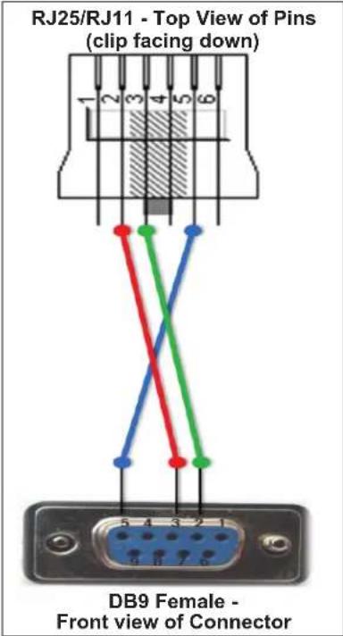
| DB9 Pins |
| 2 - Data Receive |
| 3 - Data Transmit |
| CONNECTION |
| 5 - Digital Ground |
| 6 - NOT USED NO CONNECTION |
| 7 - NOT USED NO CONNECTION |
| 8 - NOT USED NO CONNECTION |
| 9 - NOT USED NO CONNECTION |
FAULT CONDITIONS
The unit is designed to prevent damage to itself and associated components. These extensive features protect both the critical circuitry of the amplifier itself and shield connected loudspeakers from serious damage due to high power levels. Basic protections designed into the amplifier include fuses to protect against excessive current conditions, such as driving shorted outputs. Inrush limiting prevents premature aging of the power supply components during power-up; once the power supply has been charged, this feature goes offline until the amplifier is powered up again.
The amplifier actively monitors operating temperature, output current demands and the presence of DC on the outputs. The amplifier will shut down under any of these conditions and report the fault via the front panel LED.
NON-CRITICAL FAULTS
Non-critical faults are indicated by a flashing white LED on the front panel. They are neither caused by nor harmful to the amplifier. Non-critical faults either clear themselves over time (such as over temperature) or are easily remedied by the owner without dealer or factory intervention (such as shorted speaker terminals). Examples of non-critical faults are:
• Heatsink or internal temperature is above safe operating limits
- Incorrect AC mains configuration
- DC detected at input
- Shorted speaker terminals or extremely low impedance load connected
If a non-critical fault occurs, check the speaker cables and terminals and the operation of the preamp in the system. Turn off the AC power to clear the fault, and then turn the unit on again after fixing the issue. If the amplifier is too hot, wait for it to cool down. When it reaches a safe operating temperature you will be able to turn it on again.
If you are unable to remedy a non-critical fault condition, please contact your retailer or installer for assistance.
CRITICAL FAULTS
Critical faults are indicated by a steadily glowing white LED on the front panel. They may be an indication of severe problems or internal damage to the amplifier. The owner is advised to call the dealer or installer in the case of a critical fault, as it may indicate that the amplifier requires service. Examples of critical faults are:
- Left or right heatsink thermal cutoff switch over temperature
• Transformer over temperature - DC detected at output (not caused by DC at the input)
- Blown fuses
• Extreme short circuit condition at amplifier output
In the event of a surge or brown out on the AC mains, the amplifier's protection circuitry may detect mains voltage or DC rail voltage that is out of the spec. Under those conditions the amplifier may turn off to protect itself and display a critical fault. If your amplifier is displaying a critical fault and you suspect a surge or brown out, turn off the AC power, wait 10 seconds for the fault to clear, then try turning on the amplifier again.
All critical faults require that the amplifier's AC power be turned off in order to be cleared. However, the owner is advised to call the dealer or installer in the case of a critical fault, as it may indicate that the amplifier requires service.

HARMAN International Industries, Incorporated 8500 Balboa Boulevard Northridge, CA 91329 USA
© 2016 HARMAN International Industries, Incorporated. All rights reserved.
Mark Levinson and Clari-Fi are registered trademarks of HARMAN International Industries, Incorporated.
This document should not be construed as a commitment on the part of HARMAN International Industries, Incorporated. The information it contains, as well as the features, specifications and appearance of the product, is subject to change without notice. HARMAN International Industries, Incorporated, assumes no responsibility for errors that may appear within this document.
FCC Notice
This equipment has been tested and found to comply with the limits for a Class B digital device, pursuant to Part 15 of the FCC Rules. These limits are designed to provide reasonable protection against harmful interference in a residential installation. This equipment generates, uses and can radiate radio frequency energy and, if not installed and used in accordance with the instructions, may cause harmful interference to radio communications. However, there is no guarantee that interference will not occur in a particular installation. If this equipment does cause harmful interference to radio or television reception, which can be determined by turning the equipment off and on, the user is encouraged to try to correct the interference by one or more of the following measures:
• Reorient or relocate the receiving antenna.
- Increase the separation between the equipment and the receiver.
- Connect the equipment into an outlet on a circuit different from that to which the receiver is connected.
- Consult the dealer or an experienced radio/TV technician for help.
Caution! Changes or modifications not expressly approved by the party responsible for compliance could void the user's authority to operate the equipment.
Canada: This Class B digital apparatus complies with Canadian ICES-003.
For customer service and product shipment information, refer to our website: marklevinson.com
Part No. 070-90029 Rev: 2.0
Nº 536
AMPLIFICADOR MONOAURAL
Nº 534
MANUAL DEL PROPIETARIO DEL
AMPLIFICADOR DUAL-MONO AURAL
ÍNDICE
Acerca de este documento 21
| Please edit the options you need to change and save this file | |||
| # - | Description | (access) = | Option |
| 1 - | Device Name | (ReadOnly) = | MLNo536 |
| 2 - | Factory Default | (ReadWrite) = | No |
| 3 - | DebugZones | (ReadWrite) = | 00001000 |
| 4 - | Ethernet Ready | (ReadOnly) = | No |
| 5 - | DHCP (yes/no) | (ReadWrite) = | Yes |
| 6 - | IP address | (ReadOnly) = | 169.254.55.56 |
| 8 - | Network Mask | (ReadOnly) = | 255.255.255.0 |
| 9 - | Network Gateway | (ReadOnly) = | 255.255.255.0 |
| 10 - | MAC Address | (ReadWrite) = | 00:16:5a:00:02:a6 |
| 11 - | NETBIOS name | (ReadWrite) = | MLN0536X |
| 12 - | StandbyMode (G/P/N) | (ReadWrite) = | Normal |
| 13 - | TrigOut delay(sec) | (ReadWrite) = | 1 |
HARMAN International Industries, Incorporated 8500 Balboa Boulevard Northridge, CA 91329 USA
© HARMAN International Industries, Incorporated, 2016. Tous droits réservés.
| Please edit the options you need to change and save this file | |||
| # - | Description | (access) = | Option |
| 1 - | Device Name | (ReadOnly) = | MLNo536 |
| 2 - | Factory Default | (ReadWrite) = | No |
| 3 - | DebugZones | (ReadWrite) = | 00001000 |
| 4 - | Ethernet Ready | (ReadOnly) = | No |
| 5 - | DHCP (yes/no) | (ReadWrite) = | Yes |
| 6 - | IP address | (ReadOnly) = | 169.254.55.56 |
| 8 - | Network Mask | (ReadOnly) = | 255.255.255.0 |
| 9 - | Network Gateway | (ReadOnly) = | 255.255.255.0 |
| 10 - | MAC Address | (ReadWrite) = | 00:16:5a:00:02:a6 |
| 11 - | NETBIOS name | (ReadWrite) = | MLN0536X |
| 12 - | StandbyMode (G/P/N) | (ReadWrite) = | Normal |
| 13 - | TrigOut delay(sec) | (ReadWrite) = | 1 |
HARMAN International Industries, Incorporated
8500 Balboa Boulevard
Northridge, CA 91329 USA
© 2016 HARMAN International Industries, Incorporated. 保留所有权利。
| # - | Description | (access) = | Option |
| 1 - | Device Name | (ReadOnly) = | MLNo536 |
| 2 - | Factory Default | (ReadWrite) = | No |
| 3 - | DebugZones | (ReadWrite) = | 00001000 |
| 4 - | Ethernet Ready | (ReadOnly) = | No |
| 5 - | DHCP (yes/no) | (ReadWrite) = | Yes |
| 6 - | IP address | (ReadOnly) = | 169.254.55.56 |
| 8 - | Network Mask | (ReadOnly) = | 255.255.255.0 |
| 9 - | Network Gateway | (ReadOnly) = | 255.255.255.0 |
| 10 - | MAC Address | (ReadWrite) = | 00:16:5a:00:02:a6 |
| 11 - | NETBIOS name | (ReadWrite) = | MLN0536X |
| 12 - | StandbyMode (G/P/N) | (ReadWrite) = | Normal |
| 13 - | TrigOut delay(sec) | (ReadWrite) = | 1 |
HARMAN International Industries, Incorporated
8500 Balboa Boulevard
Northridge, CA 91329 USA
© 2016 HARMAN International Industries, Incorporated. 無断複写・複製・転載禁止。