
PK 255 - Saw METABO - Free user manual and instructions
Find the device manual for free PK 255 METABO in PDF.
| Technical Features | METABO PK 255 circular saw with powerful motor, 255 mm cutting capacity, adjustable cutting depth. |
|---|---|
| Usage | Ideal for cutting wood, panels, and similar materials. |
| Maintenance and Repair | Regularly check the blade condition, clean sawdust residues, lubricate moving parts. |
| Safety | Use safety glasses, gloves, and a dust mask. Never remove blade guards. |
| General Information | Lightweight for easy handling, 2-year manufacturer warranty, compatibility with various METABO accessories. |
Frequently Asked Questions - PK 255 METABO
Download the instructions for your Saw in PDF format for free! Find your manual PK 255 - METABO and take your electronic device back in hand. On this page are published all the documents necessary for the use of your device. PK 255 by METABO.
USER MANUAL PK 255 METABO
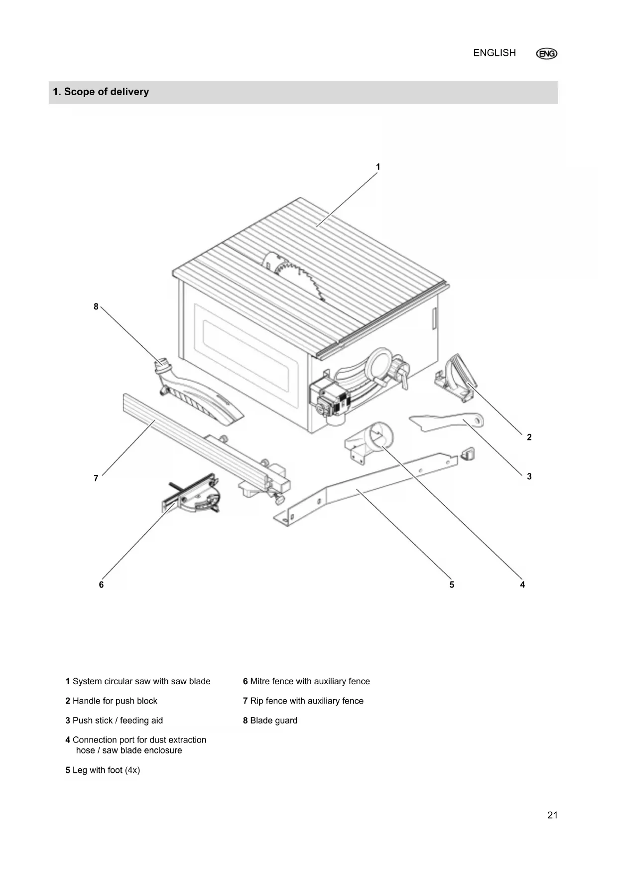
1. Scope of delivery
1 System circular saw with saw blade 2 Handle for push block 3 Push stick / feeding aid 4 Connection port for dust extraction hose / saw blade enclosure 5 Leg with foot (4x) 6 Mitre fence with auxiliary fence 7 Rip fence with auxiliary fence 8 Blade guard I_0015en2A.fm 27.4.11 Original op erating instructionsENGLISH
9 Blade guard 10 Rip fence with auxiliary fence 11 Push stick / feeding aid 12 Handwheel for setting the depth of cut 13 Handwheel for tilt angle adjust- ment with locking lever 14 On/Off switch with emergency stop 15 Mains connection 16 Legs 17 Saw blade 18 Riving knifeENGLISH
1. Scope of delivery....................21
2. Machine overview...................22
3. Please Read First! ..................23
4. Safety Instructions.................23
4.1 Specified Conditions of Use .....23
4.2 General Safety Instructions ......23
7.6 Connecting the dust collector ...28
8.1 Setting the depth of cut ............30
8.2 Setting the saw blade tilt ..........30
8.3 Sawing with the rip fence .........30
8.4 Sawing with the mitre fence .....31
10.3 Drive belt tensioning.................33
10.4 Aligning the riving knife ............34
10.5 Adjusting the saw blade tilt.......34
13. Available accessories .......36/75
These instruction have been written in a way which facilitates learning of how to safely operate your saw. Here is a guide on how you should read these in- structions: – Read these instructions before use. Pay special attention to the safety information. – These instructions are intended for persons with basic technical know- ledge regarding the operation of a
evice like the one described her- ein. Inexperienced persons are strong ly advised to seek competent advise and guidance from an expe- rienced person before operating this machine. – Keep all documents supplied with this machine for future reference. Retain proof of purchase in case of warranty claims. – This device must not be sold or lent to someone else without being ac- companied by these Operating In- structions and all other documents
pplied with the device. – The equipment manufacturer is not
iable for any damage resulting from neglect of these operating instruc- tions. Information in these instructions is desi- gnated as under: ADanger! Risk of personal injury or environmental
mage. BRisk of electric shock! Risk of personal injury by electric shock
cDrawing-in/trapping hazard! Risk of personal injury by body parts or clo thing being drawn into the rotating saw blade. A Caution! Risk of material damage. 3 Note: Additional information. – Numbers in illustrations (1, 2, 3 etc.) – denote component parts; – are consecutively numbered; – relate to the corresponding num- ber(s) in brackets (1), (2), (3) etc. in the neighbouring text. – Numbered steps must be carried
t in sequence. – Instructions which can be carried
t in any order are indicated by a bullet point (•). – Listings are marked by a dash (–).
4.1 Specified Conditions of
Use This machine is intended to rip and crosscut grown timber, faced boards, chip board and wood-core plywood sheets, and similar wood-derived mate- rials. Round workpieces may not be sawed as they can be twisted by the rotating saw blade. Any other use is considered to be not as specified and not allowed. The ma- nufacturer is not liable for any damage cause d by unspecified use. Reconstruction of this machine or use of parts that have not been tested and released by the manufacturer can lead to unforeseen damage and dangers du- ring operation.
4.2 General Safety Instruc-
tions When using this machine, observe the following safety instructions to exclude the risk of personal injury or material damage. Please also observe the special sa- fety instructions in the respective sections. Where applicable, follow the legal directives or regulations for the pre- vention of accidents pertaining to the use of circular saws. AGeneral hazards! Keep your work area tidy – a messy work area invites accidents. Be alert. Know what you are doing. Set out to work with reason. Do not operate device while under the influ- ence of drugs, alcohol or medicati- on. Table of Contents
3. Please Read First!
Consider environmental conditions. keep work area well lighted. Prevent adverse body positions. Ensure firm footing and keep your balance at all times. Use suitable workpiece supports when cutting long stock. Wedges may only be cut using a wedge cutting jig adapted to the desired wedge thickness, length and taper: – Install riving knife and blade guard. With your right hand push the wedg e cutting jig against the rip fence, while at the same time feed it into the saw blade. Secure workpi- ece with your left hand. Do not operate the machine near in- flammable liquids or gases. The saw shall only be started and operated by persons familiar with circular saws and who are at any time aware of the dangers asso- ciated with the operation of such
achine. Persons under 18 years of age shall use this machine only in the course of their vocational training, under the supervision of an instructor. Keep bystanders, particularly child- ren, out of the danger zone. Do not permit other persons to touch the machine or power cable while it is running. Do not overload device – use it only within the performance range it was designed for (see “Technical Speci- fications”).
Danger! Risk of electric shock! Do not expose device to rain. Do not operate device in damp or
et environment. Prevent body contact with earthed obje cts such as radiators, pipes, cooking stoves and refrigerators when operating this device. Do not use the power cable for pur- poses it is not intended for. ARisk of personal injury and crushing by moving parts! Do not operate the machine without installed guards. Always keep sufficient distance to the saw blade. Use suitable feeding aids, if necessary. Keep sufficient distance to driven components when operating the machine. Wait for the saw blade to come to a complete stop before removing cut- outs, waste wood etc. from the work area. Do not attempt to stop the saw bla- de by pushing the workpiece against its side. Ensure tool is disconnected from power supply before servicing. When turning ON the machine (e.g. after servicing) ensure that no tools or loose parts are left on or in the machine. Turn power OFF if the machine is not used. ACutting hazard, even with the cutting tool at standstill! Wear gloves when changing cutting tools. Store saw blades in such a manner that nobody can get hurt. ARisk of kickback (workpiece is caught by the saw blade and thrown against the operator)! Always work with a properly set ri- ving knife. Do not jam workpieces. Make sure the saw blade is suitable for the workpiece material. Cut thin or thin-walled work pieces only with fine-toothed saw blades. Always use sharp saw blades. If in doubt, check workpiece for in- clusion of foreign matter (e.g. nails or screws). Cut only stock of dimensions that al- low for safe and secure holding while cutting. Never cut several workpieces at the same time – and also no bundles containing several individual pieces. Risk of personal injury if individual pieces are caught by the saw blade uncontrolled. Remove small cut-outs, waste wood etc. from the work area – when you are doing so, the saw blade must be at a complete standstill. cDrawing-in/trapping hazard! Ensure that no parts of the body or clothing can be caught and drawn in by rotating components (no ties, no gloves, no loose-fitting clothes; con- tain long hair with hairnet). Never attempt to cut any workpi- eces which contain – ropes, – strings, – bands, – cables or – wires, or to which any of the
ove are attached. AHazard generated by insuffici- ent personal protection gear! Wear hearing protection. Wear safety goggles. Wear dust mask. Wear suitable work clothes. When working outdoors wearing of non-slip shoes is recommended. ARisk of injury by inhaling wood dust! Some types of wood dust (e.g. oak, beech, ash) may cause cancer when inhaled. If working in a closed room, always use a dust collector. Ensure that as little as possible wood dust will get into the environ- ment: – install dust collector; – fix any leakages on the dust ex- tractor; – ensure good ventilation. Operation without a dust extractor is
ly possible: – outdoors; – for short-term operation (up to a maximum of 30 minutes); – when wearing a dust respirator. AHazard generated by modi- fication of the machine or use of parts not tested and approved by the manufacturer! Strictly follow these instructions when assembling the device.ENGLISH
Use only parts approved by the equipment manufacturer. This ap- plies especially for: – saw blades (see 'Available Ac- cessories' for stock nos.); – safety devices (see "Spare Parts List" for stock numbers). Do not change any parts. AHazard generated by machine defects! Keep device and accessories in good repair. Observe the mainte- nance instructions. Prior to any use check the machine for possible damage: before opera- ting the machine all safety devices, protective guards or slightly dama- ged parts need to be checked for prope r function as specified. Check to see that all moving parts work properly and do not jam. All parts must be correctly installed and meet all conditions necessary for a proper operation of the device.
Damaged protection devices or parts must be repaired or replaced by a qualified specialist. Have damaged switches replaced by a Service Cen- tre. Do not operate tool if the switch
n not be turned ON or OFF. Keep handles free of oil and grease. ARisk of injury by noise! Wear hearing protection. Make sure the riving knife is not bent. A bent riving knife will push the workpiece against the side of the saw blade, causing noise. ADanger from blocking workpi- eces or workpiece parts! If blockage occurs:
4.3 Symbols on the machine
Data on the nameplate Symbols on the machine
Riving knife The riving knife (33) prevents the work- piece from being caught by the rising teeth of the saw blade and being thrown back against the operator. Always have riving knife installed du- ring operation. Blade guard The blade guard (34) protects against unintentional contact with the saw bla- de and from chips flying about. Always have the blade guard installed during operation. Push Stick The push stick (35) serves as an exten- sion of the hand and protects against accidental contact with the saw blade. Always use the push stick if the di- stance between saw blade and rip fence is less th an 120 mm. Guide the push stick at an angle of 20 to 30 to the surface of the saw table. If if the push stick is not re quired it can be stored in the holder (36) on the ma- chine. Replace the push stick if damaged. 19 Manufacturer 20 Article number and serial number 21 Machine designation 22 Motor data (see also 'Technical
ta') 23 Date of manufacture 24 CE-mark – This machine con- forms to the EC Directives as per
eclaration of Conformity 25 Waste disposal symbol – Machine can be disposed of by returning it to the manufacturer 26 Dimensions of permissible saw
t environment. 30 Read operating instructions 31 Do not reach into saw blade area 32 Hazardous area warning
Handle for push block The handle for the push block (38) is screwed to a matching board (37). It is used for safe guidance of relatively smal l workpieces. The board should be between 300 and
0 mm long, 80 to 100 mm wide and
to 20 mm high The push block handle must be re- placed if damaged. – Stepless tilt angle adjustment from 0° to 45°. – Stepless depth of cut setting to 80 mm. – All operating elements are located at the machine's front. – Aluminium table top and fences –
r precise cuts. – Torsion-free sheet steel machine enclo sure. – Table extension is standard delive- ry. – Can be extended for a wide range of a pplications. – Sawdust-tested in compliance with TRGS 553 by FPH. ON/OFF switch To start = press green switch button (40), . To stop = press the red switch but- ton (39) or the cover (41) of the ON/ OFF switch. The ON/OFF switch can be additionally secu red with a padlock. 3 Note: In case of a power failure an undervol- tage relay trips. This prevents the po- wer tool from starting when the power is restored. To restart, press the green switch button again. Handwheel for tilt angle adjustment The saw blade can be steplessly adju- sted from 0 to 45 with th e handwheel (42). 3 Note: The pivot is at the same height as the saw table so that the cutting depth re- mains constant for all tilt angles. For the set tilt angle to remain un- changed during sawing it must be fixed
th the locking lever (43). If the locking lever does not have a suf- ficient swivelling range for adjustment it can be repositioned: Pull out the locking lever, turn and re-engage. Handwheel for setting the depth of cut The cutting depth can be adjusted through turning of the handwheel (44). Fences The saw is equipped with two fences. Mitre fence (for cross-cuts / mitre cuts): The mitre fence can be inserted into the slot in the sliding carriage or the slot (48) in the saw table. The fence extrusion can be swivelled 45° both ways for mitre cuts. – Locking lever (47) for fixing the ang- le. – Knurled nuts (45) for fence extrusi- on position adjustment. The plastic
g (46) on the fence extrusion must point towards the saw blade at a mi- nimum distance of 10 mm to the saw bl ade.
Rip fence (for ripping): It is mounted on the guide extrusion at the front of the saw table. – During sawing the rip fence must be parallel to the saw blade and fixed in place with the wing screw (50). – Knurled nuts (49) for attaching the fence extrusion. After loosening the two knurled nuts , the fence extrusi- on can be removed and shifted: (52) Small edge: – for cutting thin stock. – when the saw blade is tilted. (51) Wide edge: – for cutting thick stock 3 Note: The scale's zero position is adjusted
ith reference to the wide edge.When the small edge of the fence extrusion is installed, there will be a 25 mm offset from th e reading. ADanger! Modifications to the saw or use of
arts not tested and released by the manufacturer can lead to unforeseen damage during operation! – Assemble the saw in strict accor- dance with these instructions. – Use only the parts supplied as
tandard delivery. – Do not change any parts. Only if you follow the instructions exact- ly does the saw conform to the safety reg ulations and can be safely operated. If you also observe the follo wing notes, the assembly will cause no problems: Read the instructions for each step before executing it. Lay out the parts required for each assembly step.
7.1 Installing the Legs
1. Turn the saw over and place it on
2. Put a rubber foot on each leg (on
3. Put the legs in the recesses at the
rners of the machine enclosure.
4. Position yourself on the operator si-
5. Fasten the front left leg using three
exagon head screws and one cap screw. (The cap screw is used as a seat for the push block handgrip.) – 3 ea. M8×16 hexagon head screw; – M8×60 cap screw; – 5 ea. serrated lock washer; – 5 ea. washer; – 5 ea. hexagon nut. The fifth piece in each case is used for locking the c ap screw.
6. Fasten the remaining legs using the
following for each leg: – 4 ea. M8×16 hexagon head screw; – 4 ea. serrated lock washer; – 4 ea. washer; – 4 ea. hexagon nut.
7. Stand saw on its four legs.
8. Fully tigthen the fastening screws
tion 3 Note: For packaging purposes the ON/OFF switch is pre-install ed in just one moun- ting hole on the saw and swivelled in- wards. For final installation of the ON/
1. Unscrew the hexagon head screw
d flange nut from the second mounting hole.
2. Rotate the switch plate with ON/
OFF switch outwards as illustrated and fasten using the hexagon head screw and flange nut. A Caution! Make sure the cable does not run
er sharp edges and is not bent.
7.3 Blade guard installation
Install the blade guard (55) on the riving knife (53) as illustrated and secure in place with the locking le- ver (54). 3 Note: The blade guard should be tilted slightly
ownward on the operator side after being correctly installed on the riving knife.
7.4 Fastening to Floor
The machine must be anchored by the legs to the floor. Use the supplied mounting brackets (57) for this.
1. Put mounting bracket (57) against
the outside of the leg (56).
2. Put washers on the hex. head
screws (58) and fit screws in the ho- les provided in mounting bracket and leg.
3. Screw flange nuts (59) on the hex.
head screws, but do not tighten yet.
4. When all mounting brackets are in-
stalled on the legs the brackets can be anch ored to the floor.
he floor move the brackets up or down as required. If necessary, loo- sen flange nuts to do so.
6. When the machine stands firm and
secure, tighten all flange nuts hand- tight.
1. Install the table extension with he-
xagon head screws, washers and self-locking nuts on the seat at the saw table. Tighten all screwed con- nections hand-tight.
2. Fit the lower end of the support strut
nto the slots provided below the be- vel tilt adjustment and push it to the
3. Attach support strut with carriage
bolts, was hers and self-locking hex. nuts to the table extension. Tightening the screwed connections Check all screwed connections of the saw . Tighten the screwed connections hand-tight using a suitable tool. When tightening the screws, bear in min d the following: – The machine must be secure and
rizontal after the screws have been tightened. – Align table extension by means of the bolted connection with the saw table: the table extension's top must be parallel with and at the same height as the saw table's top.
7.6 Connecting the dust coll-
ector ADanger! Some types of wood dust (e.g.
ech, oak, ash) may cause cancer when inhaled. Use suitable dust ex- tractor when working in enclosed
aces. The dust collector must comply with the following requirements: – hoses must fit the outer diameter of the dust extraction ports (blade guard 38 mm; chip case 100 mm); – air volume 460 m3/h; – vacuum at the dust extraction port of th e saw 530 Pa; – air speed at dust extraction port of saw 20 m/s. Also follow the operating instructions
pplied with the dust collector! The ports for dust extraction are found
the saw blade enclosure and the blade guard. Dust extraction for saw blade
2. Lower saw blade fully.
3. Turn over saw and set down with
the table facing down.
4. Remove transport support inside
onto the saw blade enclosure: – 3 ea. M6×16 hexagon head screw – 3 ea. washer – 3 ea. serrated washer – 3 ea. M6 hexagon nut.
6. Place the saw upright again.
7. Raise saw blade fully.
8. Install blade guard on the riving kni-
fe. 3 Note: The blade guard should be tilted slightly
ownward on the operator side after being correctly installed on the riving knife. 3 Note: If you are working with a dust collector,
u should now connect the dust ex- traction port (60) on the saw blade en- closure to the dust collector. Dust extraction for blade guard
1. Install blade guard on the riving kni-
fe . 3 Note: The blade guard should be tilted slightly
ownward on the operator side after being correctly installed on the riving knife. 3 Note: If you are working with a dust collector,
u should now connect the dust ex- traction port (61) on the blade guard to the dust collector.
7.7 Mains connection
BDanger! High voltage Operate saw in dry environment on- ly. Operate saw only on a power source matching the followin g requirements (see also 'Technical Data'): – Outlets properly installed,
arthed, and tested. – three-phase outlets with neutral wire installed; – Mains voltage and system fre- quency conform to the voltage and frequency shown on the ma- chine's rating label. – Protection against electric shock
a residual current device (RCD) of 30 mA sensivity. – Fuse protection of 16 A maximum against short circuits. – System impedance Z max. at the house service connection: see separate supplementary sheet. 3 Note: Contact your Electricity Board or a qua- lified electrician if you are not sure if you r house service connection meets these requirements. Make sure that the mains cable is out of the way so that it does not in- terfere with the work and cannot be
amaged. Protect mains cable from heat, ag- gressive liquids and sharp edges. Use only rubber-insulated extension cables with sufficient cross sections (see 'Technical Data'). Do not pull on mains cord to unplug. BChanging the direction of ro- tation! (only possible for version with DC motor) Depending on the wiring of the elec- trical connection the saw blade may rotate the wrong way. This can lead to the workpiece being hurled away when attempting to make a cut. The direction of rotation must therefore be checked every time the saw is connected to another outlet. In case of an incorrect direction of rotation, the wiring of the outlet must be changed by a qualified electrician:
1. After the saw and all of its safety
vices have been assembled, con- nect it to the mains supply.
2. Raise saw blade fully.
3. Start saw and switch OFF immedia-
4. Check the saw blade's direction of
rotation from the left-hand side of the saw. The saw blade must rotate clockwise.
5. If the saw blade rotates anticlockwi-
se, unplug the power cable at the saw.
6. Have the electric supply changed
y a qualified electrician! ARisk of injury! This saw may only be operated by
e person at a time. Other persons shall stay only at a distance to the saw for the purpose of feeding or re- moving stock. Before starting work, check to see tha t the following are in proper wor- king order: – mains cable and plug; – ON/OFF switch; – riving knife; – blade guard; and – feeding aids (push stick, push block
d handle). Use personal protection gear: – dust mask; – ear protection; and – safety goggles. Assume proper operating position: – in front of the saw on the operator side; – in front of the saw; – to the left of the line of cut; and – if work is being carried out by two
rsons, with the other person re- maining at an adequate distance to the saw. If the type of work requires it, use the following:
– suitable workpiece supports – if otherwise workpiece would fall off the table after being cut – dust extractor. Avoid typical operator mistakes: – Do not attempt to stop the saw bla- de by pushing the workpiece against its side. This poses a risk of kickback. – Always hold the workpiece down on the table and do not twist it. This po- ses a risk of kickback. – Never cut several workpieces at the same time – and also no bundles containing several individual pieces. Risk of personal injury if individual pieces are caught by the saw blade uncontrolled. cDrawing-in/trapping hazard! Never cut workpieces to which ro- pes, cords, bands, cables or wires
re attached or workpieces which contain any of these materials.
8.1 Setting the depth of cut
ADanger! Parts of the body or objects in the
djustment area can be caught by the running saw blade! Set the depth of cut only with the saw blade at standstill! The saw blade's cutting height needs to be adapted the the height of the workpi- ece: the blade guard shal l rest with its front edge on the workpiece. Adjust depth of cut by turning the handwheel (62) as required. – Turning to the right = increase cutting depth – Turning to the left = decrease cutting depth 3 Note: To compensate for possible play in the
ade height setting mechanism, al- ways raise the blade to the desired po- sition from below.
8.2 Setting the saw blade tilt
ADanger! Parts of the body or objects in the
justment area can be caught by the running saw blade! Set the saw blade tilt only with the saw blade at standstill!!
1. Loosen the locking lever (64) about
2. Set the desired saw blade tilt using
3. Fix the tilt angle by tightening the
8.3 Sawing with the rip fence
1. Lower the rip fence onto the guide
rail on the front of the saw.
2. Adapt the fence extrusion to the
orkpiece height (see "Workpiece fences" in chapter "Operating ele- ments") and secure in place with the
3. Set the cutting width and secure in
ace with the wing screw (66).
4. Set the saw blade cutting depth
(see "Setting the depth of cut" in chapter "Operation") and secure in place. The blade guard must rest with its front edge on the workpiece.
5. Set the saw blade tilt angle (see
"Se tting the saw blade tilt" in chap- ter "Operation") and secure in
ADanger! Always use the push stick if the di- stance between saw blade and rip fen ce is less than 120 mm.
7. Guide the workpiece slowly along
the rip fence up to the saw blade and cut in a single pass.
8. Turn machine off if no further cutting
is to be done immediately after- wards.
Setting the rip fence for ripping solid wood Set the rear end of the rip fence (67) at a position corresponding to the midpoint between the saw spindle and the saw blade tip . A Caution! After every cutting operation use the
ush stick to guide the workpiece care- fully between the saw blade and the rip fen ce to the rear area of the saw table and remove it from the table. Setting the rip fence for cutting boards Set the rear end of the rip fence (68) to the maximum possible length, or at least such that it is in
ine with the saw spindle . A Caution! After every cutting operation use the push stick to guide the workpiece care- fully between the saw blade and the rip fence to the rear area of the saw table and remove it from the table. Setting the rip fence for cross-cut- ting narrow workpieces Set the rear end of the rip fence (69) such that it is in line with the saw blade tip. ADanger! If the workpiece is wedged it can be flun g out uncontrolledly. Adjust the rip fence such that the workpiece ends are not simultaneously contacting the saw blade and the rip fence. A Caution! After every cutting operation use the push stick to guide the workpiece care- fully between the saw blade and the rip fence to the rear area of the saw table and remove it from the table.
slot from the table’s front edge.
2. Set the desired mitre angle and se-
cure in place with the locking lever (72).
3. Align fence extrusion and arrest in
sition with knurled thumb screws (70). A Caution! The plastic lug (71) must be at a di- stance of at least 10 mm from the cut- ting line.
4. Set the saw blade cutting depth and
secure in place (see "Setting the depth of cut" in chapter "Operati
on"). The blade guard must rest with its front edge on the workpiece.
5. Set the saw blade tilt angle and se-
cure in place (see "Setting the saw
ade tilt" in chapter "Operation").
7. Slide the workpiece against the mit-
re fence, hold and cut in a single pass.
8. Turn machine off if no further cutting
is to be don e immediately after- wards.
Before making a cut: make a trial cut on appropriate waste pieces. Always lay the workpiece on the saw table such that it cannot tip over or wobble (e.g. place a curved board with the convex side up). For long workpieces: use suitable workpiece supports, for example roller support or extension table (see 'Available Accessories'). Keep surfaces of the table top and table extension clean – in particular, remove resin residue with a suitable cleaning and maintenance spray (optional accessory). ADanger! Unplug before servicing. – Repair and maintenance work other than described in this section should only be carried out by quali
fied specialists. – Damaged parts, particularly safety device s, must only be replaced with genuine parts. Parts which have not been tested and released by the manufacturer can lead to unfore- seen damage. – Check that all safety devices are ope rational again after each ser- vice.
10.1 Saw Blade Change
ADanger! Directly after cutting the saw blade may
very hot – burning hazard! Let a hot saw blade cool down. Do not clean the saw blade with combustible liquids. Risk of injury, even with the blade at standstill. Wear gloves when changing blades. When fitting a saw blade, observe the direction of rotation!
1. Unscrew the fastening screws (73)
of the table insert and remove the table insert.
2. Raise saw blade fully.
3. Remove blade guard.
4. Raise the swivel box lid slightly and
swing to the side. The swivel box lid is hinged at the bottom and cannot come off.
5. To lock the saw blade in place in-
sert the locating pin from above into the hole drilled in the saw table. To do this slowly rotate the saw blade until the locating pin engages.
6. Remove the spindle nut (79) from
the saw spindle (76) using a span- ner (left-hand thread!).
7. Carefully take the outer blade collar
(78) off the saw spindle. Hold the saw blade while doing so.
8. Remove the saw blade and inner
blade collar (74) from the saw spindle.
9. Clean the saw blade, saw spindle,
outer blade collar and inner blade collar. ADanger! Do not use cleaning agents (e.g. to rem ove resin residue) that could cor- rode the light metal components of the saw; the stability of the saw would be adversely affected.
10. Mount the inner blade collar on the
saw spindle. The driving pin (77) on the saw spindle must be engaged in the hole drilled in the blade collar.
11. Put on a fresh saw blade (observe
direction of rotation!). The driving pin (77) on the saw spindle must be engaged in one of the two holes dri lled in the saw blade. ADanger! Use only suitable saw blades (see 'Available Acc essories') – when using unsuitable or damaged blades parts could be flung out explosively by centrifugal force. Do not use: – saw blades made of high- strength steel (HSS or HS); – saw blades with visible damage;
– cut-off wheel blades. ADanger! – Mount saw blade only using ge- nuine parts. – Do not use loose-fitting reducing rin gs; the saw blade could work loose. – Saw blades have to be mounted in such way that they do not wobble or run out of balance and can not work loose during operation.
12. Mount the outer blade collar on the
saw spindle. The driving pin (77) on the saw spindle must be engaged in the hole drilled in the blade collar.
10. Care and maintenance
13. Screw the spindle nut onto the saw
spindle (left-hand thread!) and tigh
ten hand-tight. ADanger! – Do not extend the tool for tighte- ning the arbor bolt. – Do not tighten the spindle nut by ham mering on the tool. – After tightening the spindle nut remove all tools used during saw blade installation!
16. Install blade guard on the riving knife.
3 Note: The blade guard should be tilted slightly
ownward on the operator side after being correctly installed on the riving knife.
10.2 Saw blade alignment
The saw blade must be exactly parallel with the edge of the saw table. The di- stance between the saw blade and the tab le edge on the right must not exceed 3 mm. Adjustment is carried out from the top
ith adjusting nuts. Then the settings made by means of the adjusting nuts are fixed with two hexagon socket screws on the underside of the saw:
1. Unscrew the fastening screws (80)
3. Raise the swivel box lid slightly and
swi ng to the side. The swivel box lid is hinged on the bottom and cannot come off.
4. Counter-tighten the adjusting nuts
(81) (two on each of the two swivel segments). A Caution! The adjusting nuts (81) on the two swi- vel segments should not be tightened during operation; this ensures that no mechanical stresses arise during sa- wing.
5. Lower saw blade fully.
6. Turn the saw over and place it on
7. Loosen two hexagon socket screws
(82) inside the saw about one turn.
8. Place the saw upright again.
9. Raise saw blade slightly.
10. Align the saw blade by adjusting the
justing nuts (81) on the two swi- vel segments.
11. Lower saw blade fully.
12. Turn the saw over and place it on
(82) inside the saw again.
14. Place the saw upright again.
A Caution! The adjusting nuts (81) on the two swi- vel segments should n ot be tightened during operation; this ensures that no mechanical stresses arise during sa- wing.
15. Loosen the adjusting nuts on the
two swivel segments about two turns.
18. Raise saw blade fully.
19. Install blade guard on the riving kni-
fe. 3 Note: The blade guard should be tilted slightly
wnward on the operator side after being correctly installed on the riving knife.
10.3 Drive belt tensioning
The drive belt runs between motor and saw spindle. The drive belt must be re- tensioned: – if it gives more than 5 mm; – if the saw blade continues rotating for m ore than 10 seconds after switch-off. Checking and re-tensioning
1. Turn the saw over and place it on
2. Unscrew the cover plate from the
pressure at the window of the belt housing.
4. If the drive belt needs to be re-ten-
sioned: loosen the four motor moun- ting screws about one turn. The motor is mounted on an eccentric. The belt tensio n is changed through rota- ting of the motor housing. Rotating the motor housing clockwi- se = decrease the belt tension.
Rotating the motor housing anticlockwi- se = increase the belt tension.
5. When the belt tension is correct
tighten the motor mounting screws crosswise.
6. Screw the cover plate back onto the
10.4 Aligning the riving knife
3 Note: The riving knife has already been ali- gned to the saw blade in the factory.
owever, it is still necessary to check the distance from the riving knife to the saw blade and if necessary align the knife at regular intervals. To align the riving knife:
1. Unscrew the fastening screws (83)
2. Raise saw blade fully.
3. Remove blade guard.
4. Raise the swivel box lid slightly and
swi ng to the side. The swivel box lid is hinged at the bottom and cannot come off. To adjust the riving knife position exact- ly to the saw blade, it is adjustable in two pla nes: – in the distance to the saw blade; – in its lateral alignment. Distance to the saw blade: – The distance between the saw bla- de's outer edge and the riving knife
all be between 3 and 8 mm. – The riving knife must project over the saw table at least as far as the saw blade does.
1. Loosen the Keps nut (85) holding
the riving knife by one turn.
2. Adjust the distance from the riving
kni fe to the saw blade.
3. Line the riving knife up with the saw
Lateral alignment: Riving knife and saw blade must be
rfectly in line. The lateral alignment of the riving knife is preset by the ma- nufacturer. In case a fine setting should become nec essary: Turn adjusting nuts (87) clockwise = riving knife moves to the right. Turn adjusting nuts (87) anticlockwi- se = riving knife moves to the left. After alignment:
3. Install blade guard on the riving kni-
fe. 3 Note: The blade guard should be tilted slightly
wnward on the operator side after being correctly installed on the riving knife.
10.5 Adjusting the saw blade
1. Raise the saw blade fully and align
at right angles to the saw table using a separate square.
2. If the 0° stop on the rear of the saw
does not precisely correspond to
the saw blade aligned at right an- gles: Adjust the stop screw by loose- ning and counter-tightening the two nuts (89) until the saw blade is precisely at right angles when it is against the 0° stop.
3. Repeat steps 1 and 2 analogously
4. Readjust the angle scale on the
fron t if necessary. To do this loosen the screws (90) and slide the angle scale in the oblong holes.
10.6 Adjusting the Scale
The scale must be adjusted according to the position and thickness of the saw blade.
1. Hold the rip fence against the right
ank of the saw blade and clamp.The 0° line on the scale must be below the left edge (arrow) of the rip fence extrusion; if not: Loosen the fastening screw (91), adjust the scale and tighten the fastening screw.
2. Remove the rip fence.
to the saw bla de and secure in place with the locking lever (92). The 0° line on the angle scale (95) must point to the middle line on the ver nier scale (94).
2. If necessary loosen the fastening
screws (93), adjust the angle scale and tighten the fastening screws
ADanger! Store saw so that – it cannot be started by unautho- rised persons and – nobody can get injured. A Caution! Do not store saw unprotected out- doors or in damp environment.
Before switching ON – Visually check whether the di- stance between the saw blade and the riving knife is 3 to 8 mm. – Visually check whether the blade
uard on the riving knife is tilted slightly downward on the operator side. – Visual check of power cable and po- wer cable plug for damage; if ne- cessary have damaged parts re- placed by a qualified electrician. – Visually check whether the saw slot is free from sawdust and chips; if necessary clear debris with a vacu- um cleaner or brush. After switching OFF Check to see if the saw blade post-runs for more than 10 seconds; if so, have the electronic motorbrake replaced by a qualified electrician. Monthly (if used daily) Remove saw dust and chips with vacu- um or brush; apply light co at of oil to guide elements: – threaded rod of height adjustment; – swivel segments. Every 300 hours of operation – Check all screwed connections and tigh ten if necessary (except the ad- justing nuts on the two swivel seg- ments for saw blade alignment). – Check the saw blade drive belt. ADanger! Repairs to power tools may only be car- ried out by qualified electricians! Electric tools in need of repair can be sent to the Service Centre of your country. The address can be found in the spare parts list. Please attach a description of the fault to the electric tool. Lower saw blade fully. Dismount add-on parts (fence, sli- ding carriage, table extension). If possible, use the original card- board box for shipping.
For special tasks the following accesso- ries are available at your specialised dealer – see back cover for illustrations: A Whe el Set B Base Suppo rt System C Exten sion incl. support leg for base support system D Additional support leg for base sup- port system E Slidi ng Carriage For convenient guiding of long stock. For installation on the left or right side of the base support system F Tab le Side Extension Plus Increases the bearing surface; ide- al for cutting boards For installation on the left or right side of the base support system G Tab le extension H Mi tre Fence For making precise cross and mitre cuts I Roller Stand RS 420 J Roll er Stand RS 420 W K Roll er Stand RS 420 G L Care and Maintenance Spray For removing resin residue and pre- serving metal surfaces. M Sucti on Adapter For connection to a dust collector. N Hand grip for push block For guiding the workpiece laterally Available Saw Blades O Saw blade TCT/CT 250 × 2.8 / 2.0 × 30, 25° 24 alternate top bevel teeth Suitable for solid wood and for rough cuts in composite materials and coated wood P Saw Blade TCT/CT 250 × 2.8 / 1.8 × 30, 15° 34 alternate top bevel teeth Suitable for softwood and hard- wood, Suitable for solid and laminated wood , particle board (raw coated or veneered), MDF and composite ma- terials Q Saw Blade TCT/CT 250 × 2.8 / 1.8 × 30, 15° 42 alternate top bevel teeth Suitable for softwood and hard- wood, Suitable for solid and laminated
ood, particle board (raw coated or veneered), MDF and composite ma- terials R Saw Blade TCT/CT 250 × 2.8 / 1.8 × 30, 15° 60 alternate top bevel teeth Suitable for softwood and hard- wood, Suitable for solid and laminated
ood, particle board (raw coated or veneered), MDF and composite ma- terials S Saw Blade TCT/CT 250 × 3.2 / 2.2× 30, 10° 60 alternate top bevel teeth Suitable for softwood and hard- wood, Suitable for solid and laminated
ood, particle board (raw coated or veneered), MDF and composite ma- terials T Saw Blade TCT/CT 250 × 2.8 / 1.8 × 30, 10° 80 alternate top bevel teeth For superior cut quality, e.g. in lami- nate and in plastic, aluminium, cop- per and brass extrusions, Perfect cutting results for solid wood
nd for raw, coated or veneered particle board and MDF U Saw Blade TCT/CT 250 × 2.8
neg. 80 trapezoid/flat teeth For superior cut quality, e.g. in lami- nate and in plastic, aluminium, cop- per and brass extrusions, Perfect cutting results for solid wood
nd for raw, coated or veneered particle board and MDF The machine's packing can be 100% recycled. End-of-life power tools and accessories contain large amounts of valuable raw materials and plastics which must be recycled. This manual was printed on chlorine- free bleached paper. ADanger! Before carrying out any fault service
maintenance work, always:
3. Wait for saw blade to come to
stan dstill. Check that all safety devices are operational again after each fault service. Motor does not run Undervoltage relay tripped by power failure: switch on again. No mains voltage check cables, plug, outlet and mains fuse. Motor overheated, e.g. by a blunt saw bla de or chip build-up in the chip case: remove cause for overheating, let cool down for a few minutes, then start again. Motor supply voltage too low: use a shorter supply line or supply line with a larger lead cross section ( 1.5 mm
have power supply checked by a qualified electrician. Loss of cutting performance Saw blade blunt (possibly tempering marks on blade body): Saw blade not suitable for material
ing cut (see section 'Technical Da- ta'); Saw blade warped: Replace saw blade (see chapter "Maintenance"). Saw dust build-up No dust collector or dust collector of in- sufficient capacity connected (see “Connecting the dust collector” in chap- ter “Installation”): connect dust collector, or increase suction capacity.
(S6 40%) Output power P
- The values stated are emission values and as such do not necessa rily constitute values which are safe for the workplace. Alt- hough there is a correlation between emission levels and environmental impact levels, whether further precautions are neces- sary cannot be derived from this. Factors influ encing the actually present environmental impact level in the workplace include the characteristics of the work area and other noise sources, i.e. the number of machines and other neighbouring work processes. Also, permissible workplace values may vary from country to country. This information is intended to assist the user in his esti- mate of hazards and risks.FRANÇAIS