
PCP2S5CHG6BRX - Built-in oven CANDY - Free user manual and instructions
Find the device manual for free PCP2S5CHG6BRX CANDY in PDF.



| Product type | Built-in gas hob |
| Brand | Candy |
| Model | PCP2S5CHG6BRX |
| Dimensions (W x D) | 595 x 510 mm |
| Approximate weight | 10 kg |
| Power supply | 220-240 V ~ 50/60 Hz |
| Gas type | Natural gas (G20) / Butane (G30) / Propane (G30) |
| Number of burners | 4 (Auxiliary, Semi-rapid, Rapid, Double ring 4 kW) |
| Ignition | Integrated electronic |
| Safety | Safety thermocouple (FFD) on each burner |
| Surface material | Stainless steel (enamel or chrome depending on parts) |
| Installation class | Class 3 (built-in) |
| Total nominal power | 9.45 kW (gas) + 1 kW (electric) |
| Maintenance | Clean after each use with soapy water, avoid abrasive products |
| Spare parts | Available from after-sales service |
| Use | Domestic non-professional |
| Compliance | CE, WEEE directive 2012/19/EU |
Frequently Asked Questions - PCP2S5CHG6BRX CANDY
User questions about PCP2S5CHG6BRX CANDY
0 question about this device. Answer the ones you know or ask your own.
Ask a new question about this device
Download the instructions for your Built-in oven in PDF format for free! Find your manual PCP2S5CHG6BRX - CANDY and take your electronic device back in hand. On this page are published all the documents necessary for the use of your device. PCP2S5CHG6BRX by CANDY.
USER MANUAL PCP2S5CHG6BRX CANDY
INSTRUCTIONS FOR USE AND INSTALLATION
COOKING HOB
INSTRUCTIONS FOR USE
HOB
INSTRUCTIONS FOR USE
HOB
- CHG63B
- CHG6BR
- CHG6D
- CHG6W
- CHW6BR
- CHW6D
CONTENT
GB-IE
Safety Instructions 05 1. Instructions For The Installer.. 06 1.1. Building In .06 1.2.Suitable Location 06 2. Electrical Connection (For U.K. Only) 06 2.1. Electrical Connection .06 2.2. Gas Connection (For U.K. Only). 06 2.3. Adapting The Hob To Different Types Of Gas.. 07 2.4.Regulating The Minimum Flame 07 3.Use Of Hob-User Instructions. 07 3.1. Using The Gas Burner 07 4. Maintenance and Cleaning 07 5. Aftercare .08 6. Protection Of The Environment 08
CONTENTS
CZ
Safety Instructions 13 1. Instructions for the Installer 14 1.1 Building In 14 1.2 Suitable Location 14 2.1 Electrical Connection 14 2.2 Gas Connection 14 2.3 Converting the Hob to a Different Type of Gas 15 2.4 Adjusting the Minimum Flame 15 3. Using the Hob 15 3.1 Using the Gas Burner 15 4. Maintenance and Cleaning 15 5. Service 15 6. Environmental Protection 16
CONTENTS
ES
We recommend you keep the instructions for installation and use for later reference, and before installing the hob, note its serial number in case you need to get help from the after sales service. WARNING: the appliance and its accessible parts become hot during use. Care should be taken to avoid touching heating elements. Children under 8 years of age must be kept away from the appliance unless they are continuously supervised.
WARNING: use only hob guards designed by the Manufacturer of the cooking appliance or indicated by the Manufacturer of the appliance in the instructions for use as suitable or hob guards incorporated in the appliance. The use of inappropriate guards can cause accidents.
WARNING: unattended cooking on a hob with fat or oil can be dangerous and may result in fire.
NEVER try to extinguish a fire with water, but switch off the appliance and then cover flame e.g. with a lid or a fire blanket.
WARNING: danger of fire: do not store items on the cooking surfaces.
WARNING: if the surface is cracked, do not touch the glass and switch off the appliance to avoid the possibility of electric shock.
This appliance can be used by children aged from 8 years and above and people with reduced physical, sensory or mental capabilities or lack of experience and knowledge if they have been given supervision or instruction concerning use of the appliance in a safe way and understand the hazards involved. Children should be supervised to ensure that they do not play with the appliance. Cleaning and user maintenance shall not be made by children without supervision.
CAUTION: the cooking process must be supervised. A short term cooking process has to be supervised continuously.
It is strongly recommended to keep children away from the cooking zones while they are in operation or when they are switched off, so long as the residual heat indicator is on, in order to prevent the risks of serious burns.
This appliance is not intended to be operated by means of an external timer or separate remote control system.
If present, do not stare into halogen lamp hob elements.
Connect a plug to the supply cable that is able to bear the voltage, current and load indicated on the tag and having the earth contact. The socket must be suitable for the load indicated on the tag and must be having the earth contact connected and in operation. The earth conductor is yellow-green in color. This operation should be carried out by a
suitably qualified professional. In case of incompatibility between the socket and the appliance plug, ask a qualified electrician to substitute the socket with another suitable type. The plug and the socket must be conformed to the current norms of the installation country.
Connection to the power source can also be made by placing an omnipolar breaker between the appliance and the power source that can bear the maximum connected load and that is in line with current legislation.
The yellow-green earth cable should not be interrupted by the breaker. The socket or omnipolar breaker used for the connection should be easily accessible when the appliance is installed.
The disconnection may be achieved by having the plug accessible or by incorporating a switch in the fixed wiring in accordance with the wiring rules.
If the supply cord is damaged, it must be replaced by Manufacturer, its service agent or similarly qualified people in order to avoid a hazard. The earth conductor (yellow-green) must be longer than 10mm on the terminal block side. The internal conductors section should be appropriate to the power absorbed by the hob (indicated on the tag). The type of power cable must be HO5V2V2-F.
Do not put metallic objects such as knives, forks, spoons or lids on the hob. They could heat up. Aluminum foil and plastic pans must not be placed on heating zones.
After every use, some cleaning of the hob is necessary to prevent the build-up of dirt and grease. If left, this is recooked when the hob is used and burns giving off smoke and unpleasant smells, not to mention the risks of fire propagation.
Never use a steam or high pressure spray to clean the appliance.
Do not touch the heat zones during operation or for a while after use.
Never cook food directly on the glass ceramic hob.
Always use the appropriate cookware. Always place the pan in the center of the unit that you are cooking on.
Do not place anything on the control panel.
Do not use the hob as a working surface.
Do not use the surface as a cutting board.
Do not store heavy items above the hob. If they drop onto the hob, they may cause damage.
Do not use the hob for storage of any items.
Do not slide cookware across the hob.
1. INSTRUCTIONS FOR THE INSTALLER
Installing a domestic appliance can be a complicated operation which, if not carried out correctly, can seriously affect consumer safety. It is for this reason that the task should be undertaken by a professionally qualified person who will carry it out in accordance with the technical regulations in force. In the event that this advice is ignored and the installation is carried out by an unqualified person, the manufacturer declines all responsibility for any technical failure of the product, whether or not it results in damage to goods or injury to individuals.
1.1 BUILDING IN
The hob may be installed in any worktop which is heat resistant to a temperature of 100°C, and has a thickness of 25 - 45 mm. The dimensions of the insert to be cut out of the worktop are shown in Figure 2.
If the hob is fitted next to a cabinet on either side, the distance between the hob and the cabinet must be at least 15 cm (see Figure 4); while the distance between the hob and the rear wall must be at least 70 mm. The distance between the hob and any other unit or appliance above it (e.g., an extractor hood) must be no less than 70 cm (Figure 4).
When there is an accessible space between the built-in hob and the cavity below, a dividing wall made of insulating material should be inserted (wood or a similar material) (Figure 3).
Metal objects in the drawer may reach high temperatures due to air recirculation. It is therefore recommended to use an intermediate wood panel.
Important - The diagram in Figure 1 shows how the sealant should be applied.
The hob unit is fitted by attaching the Fixing Clamps supplied, using the holes at the base of the unit.
If a hob of 60 cm is fitted above an oven which is not equipped with fan cooling system it is recommended that openings are created within the built in furniture to ensure correct air circulation.
The size of these openings must be at least 300 cm² and placed as shown in Figure 5.
When a 75 cm hob is fitted over a built in oven, the latter must be fan cooled.
1.2. SUITABLE LOCATION
This appliance must be installed in accordance with the regulations in force and only used in a well ventilated space. Read the instructions before installing or using this appliance.
A gas-powered cooking appliance produces heat and humidity in the area in which it is installed. For this reason you should ensure good ventilation either by keeping all natural air passages open or by installing an extractor hood with an exhaust flue. Intensive and prolonged use of the appliance may require extra ventilation, such as the opening of a window or an increase in speed of the electric fan, if you have one.
If a hood cannot be installed, an electric fan should be fitted to an outside wall or window to ensure that there is adequate ventilation. The electric fan should be able to carry out a complete change of air in the kitchen 3-5 times every hour. The installer should follow the relevant national standards.
2. ELECTRICAL CONNECTION (FOR U.K. ONLY)
Warning - this appliance must be earthed
This appliance is designed for domestic use only. Connection to the main supply must be made by a competent electrician, ensuring that all current regulations concerning such installations are observed.
The appliance must only be connected to a suitably rated spur point, a 3 pin 13 amp plug/rod is not suitable. A double pole switch must be provided and the circuit must have appropriate fuse protection. Further details of the power requirement of the individual product will be found in the users' instruction and on the appliance rating plate. In the case of built-in product you are advised, should you wish to use a longer cable than the one supplied, that a suitably rated heat resistant type must be used.
The wiring must be connected to the mains supply as follows: CONNECT TO SPUR TERMINAL
Green & Yellow Wire
Blue Wire
Brown Wire
Earth Connection
Neutral Connection
Live Connection
Note: We do not advocate the use of earth leakage devices with electric cooking appliances installed to spur points because of the “nuisance tripping” which may occur. You are again reminded that the appliance must be correctly earthed; the manufacturer declines any responsibility for any event occurring as a result of incorrect electrical installation.
2.1. ELECTRICAL CONNECTION
Check the data on the rating plate, located on the outside of the unit, to ensure that the supply and input voltage are suitable.
Before connection, check the earthing system.
By law, this appliance must be earthed. If this regulation is not complied with, the manufacturer will not be responsible for any damage caused to persons or property. If a plug is not already attached, fit a plug appropriate to the load indicated on the rating plate. The earth wire is coloured yellow/green. The plug should always be accessible.
Where the hob is connected directly to the electricity supply, a circuit breaker must be fitted.
If the power supply cord is damaged, it must be replaced by a qualified engineer to prevent any potential risk.
The earth wire (green and yellow coloured) must be at least 10 mm longer than the live and neutral wires.
The section of the cable used must be of the correct size in relation to the absorbed power of the hob.
Please check the rating plate for the power details and ensure that the power supply cord is of the type 3 × 0.75 mm² H05 V2V2-F.
| Mains Supply | LIVE | L | Brown Wire |
| EARTH | Green/Yellow Wire | ||
| NEUTRAL | N | Blue Wire |
If an appliance is not fitted with a supply cord and a plug, or with other means for disconnection from the supply mains having a contact separation in all poles that provide full disconnection under overvoltage category III conditions, the instructions shall state that means for disconnection must be incorporated in the fixed wiring in accordance with the wiring rules.
2.2. GAS CONNECTION
These instructions are for qualified personnel. Installation of equipment must be in line with the relevant national standard. (For U.K. only: by law, the gas installation/commissioning must be carried out by a "Gas Safe" installer.)
All work must be carried out with the electricity supply disconnected. The rating plate on the hob shows the type of gas with which it is designed to be used. Connection to the mains gas supply or gas cylinder should be carried out after having checked that it is regulated for the type of gas with which it will be supplied. If it is not correctly regulated, see the instructions in the following paragraphs to change gas setting.
For liquid gas (cylinder gas), use pressure regulators which comply with the relevant national standards.
Use only pipes, washers, and sealing washers which comply with the relevant national standards.
For some models, a conic link is furnished to outfit for installation in countries where this type of link is obligatory. In picture 8, it is pointed out how to recognize the different types of links (CY = cylindrical, CO = conic). In every case, the cylindrical part of the link has to be connected to the hob.
When connecting the hob to the gas supply via flexible hoses, please ensure that the maximum distance covered by the hose does not exceed 2 metres.
The flexible tube shall be fitted in such a way that it cannot come into contact with a moveable part of the housing unit (e.g., a drawer) and does not pass through any space where it may become crushed, kinked, or damaged in any way.
To prevent any potential damage to the hob, please carry out the installation following this sequence (picture 6):
1) As illustrated, assemble parts in sequence:
A: 1/2 Male Adaptor Cylindrical B: 1/2 Seal C: 1/2 Female Gas Adaptor Conical-Cylindrical or Cylindrical-Cylindrical
2) Tighten the joints with a spanner, remembering to twist the pipes into position.
3) Attach fitting C to mains gas supply using rigid copper pipe or flexible steel pipe.
IMPORTANT: carry out a final check for leaks on the pipe connections using a soapy solution. NEVER USE A FLAME. Also, make sure that the flexible pipe cannot come into contact with a moving part of the cabinet (e.g., a drawer) and that it is not situated where it could be damaged.
Warning: If gas can be smelt in the vicinity of this appliance, turn off the gas supply to the appliance and call the engineer directly. Do not search for a leak with a naked flame.
2.3. ADAPTING THE HOB TO DIFFERENT TYPES OF GAS
To adapt the hob for use with different types of gas, carry out the following instructions: - Remove the grids and burners. - Insert a hexagonal spanner (7 mm) into the burner support (Figure 7). - Unscrew the injector and replace it with one suitable for the gas to be used (see gas type table).
2.4. REGULATING THE MINIMUM FLAME
After lighting the burners, turn the control knob to the minimum setting and then remove the knob (this can easily be removed by applying gentle pressure).
Using a small "Terminal" type screwdriver, the regulating screw can be adjusted as in Figure 9. Turning the screw clockwise reduces the gas flow, whilst turning it anticlockwise increases the flow. Use this adjustment to obtain a flame of approximately 3 to 4 mm in length and then replace the control knob.
When the gas supply available is LPG, the screw to set the idle flame must be turned (clockwise) to the end stop.
When you have carried out the new gas regulation, replace the old gas rating plate on your appliance with one (supplied with the hob) suitable for the type of gas for which it has been regulated.
3. USE OF HOB - USER INSTRUCTIONS
This appliance must only be used for the purpose for which it is intended, domestic cooking, and any other use will be considered improper and could therefore be dangerous. The manufacturer will not be responsible for any damage or loss resulting from improper use.
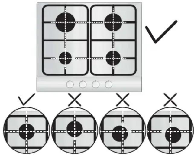
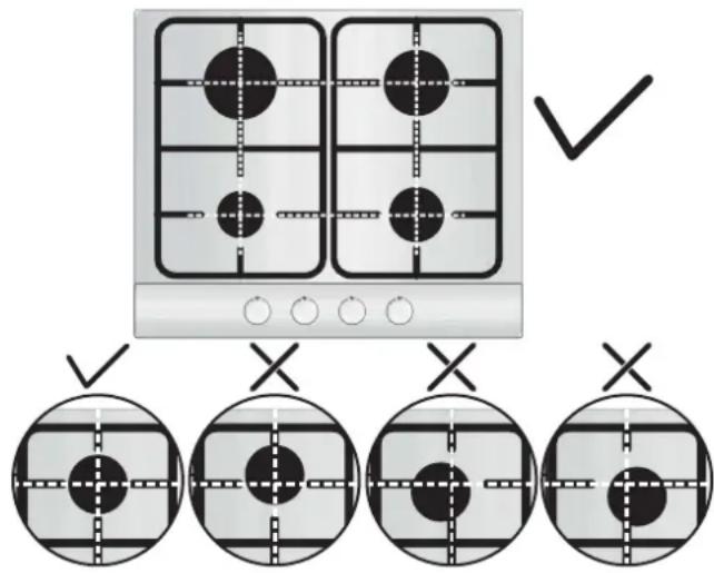
Before using a burner, be sure that the grid perimeters center the burner as shown in the figure below.
If you are using cast iron grids, underneath the grid, its position is stated. Be sure that the exact grid is used in the correct position.
To ignite the burners, place a lighted taper close to the burner, press in and turn the control knob anticlockwise. If the burners have not been used for a couple of days, wait for a few seconds before lighting the burner; this will allow any air present in the pipes to escape. For appliances fitted with electronic ignition, carry out the following: - Push in and turn the knob anticlockwise to the ignition symbol. - Ignite the burner by pressing the sparker button. For hobs fitted with automatic ignition, simply push in and turn the knob to the ignition symbol. The ignition system will continue to generate sparks as long as the control knob is being pressed. If the burner has not ignited within 5 seconds, turn the knob to the 0 position and repeat the operation. For models fitted with a safety tap (which cuts off the flow of gas if the flame is accidentally extinguished), the burners are ignited as described above, but care must be taken. Prior to switching on the gas hob, ensure that the burners and burner caps are correctly placed within their position.
Warning: If there is no electricity on the appliance, a lighter should be used to ignite the burner.
- Push in and turn the knob anticlockwise to the ignition symbol.
- While pushing in the button, ignite the burner using a lighter and keep the button pushed in for 5 seconds after ignition.
GENERAL ADVICE
For best results, use cooking vessels with a flat surface. The size of the surface should match the gas burner size as follows in Table A.
| Burner Type | Ø pan/pot (cm) | Power (kW) | G20/20 mbar (methane) | G30/28-30 mbar (LPG) |
| AUX Auxiliary | 12 - 18 | 1,00 | 95 l/h | 73 g/h |
| SR Semi Rapid | 18 - 22 | 1,75 | 167 l/h | 127 g/h |
| R Rapid | 24 - 26 | 2,70 | 257 l/h | 196 g/h |
| UR Ultrarapid | 26 - 28 | 3,50 | 334 l/h | 254 g/h |
| DC 4 kW MONO | 26 - 28 | 4,00 | 381 l/h | 291 g/h |
Table A
For smaller containers, regulate the gas burner so that the flame does not overlap the base of the pan. Vessels with a concave or convex base should not be used.
WARNING: If a flame is accidentally extinguished, turn the knob to the off position and do not attempt to re-ignite for at least 1 minute.
If over the years the gas taps become stiff to turn, it is necessary to lubricate them.
Such operation must be carried out only by qualified Service Engineers.
4. MAINTENANCE AND CLEANING
Before cleaning the hob, ensure the appliance has cooled down. Remove the plug from the socket or (if connected directly) switch off the electricity supply.
Cleaning and user maintenance shall not be made by children without supervision.
Never use abrasives, corrosive detergents, bleaching agents or acids. Avoid any acid or alkaline substances (lemon, juice, vinegar etc.) on the enamelled, varnished or stainless steel sections.
When cleaning the enamelled, varnished or chrome sections, use warm soapy water or a non-caustic detergent. For stainless steel, use an appropriate cleaning solution.
The burners can be cleaned with soapy water. To restore their original shine, use a household stainless steel cleaner. After cleaning, dry the burners and replace them.
It is important that the burners are replaced correctly.
Chromed grids and burners
Chromed grids and burners have a tendency to discolour with use. This does not jeopardize the functionality of the hob.
Our After Sales Service Centre can provide spare parts if required.
5. AFTERCARE
Before calling out a Service Engineer please check the following: - that the plug is correctly inserted and fused; - that the gas supply is not faulty.
If the fault cannot be detected:
Switch off the appliance and call the After Service Centre. DO NOT TAMPER WITH THE APPLIANCE.
6. PROTECTION OF THE ENVIRONMENT
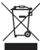
This appliance is marked according to the European directive 2012/19/EU on Waste Electrical and Electronic Equipment (WEEE). WEEE contains both polluting substances (which can cause negative consequences for the environment) and basic components (which can be re-used). It is important to have WEEE subjected to specific treatments, in order to remove and dispose properly all pollutants, and
recover and recycle all materials.
Individuals can play an important role in ensuring that WEEE does not become an environmental issue; it is essential to follow some basic rules:
- WEEE shall not be treated as household waste.
- WEEE shall be handed over to the relevant collection points managed by the municipality or by registered companies. In many countries, for large WEEE, home collection could be present.
- When you buy a new appliance, the old one may be returned to the retailer who has to collect it free of charge on a one-to-one basis, as long as the equipment is of equivalent type and has the same functions as the supplied equipment.
Declaration of compliance: This equipment, in the parts intended to come into contact with food, complies with the regulations laid down in EEC directives 89/109.
The appliance complies with European Directive 2009/142/EC (GAD) and starting from 21/04/2018 with Gas Appliances Regulation 2016/426 (GAR).
By placing the mark on this product, we are confirming compliance to all relevant European safety, health and environmental requirements which are applicable in legislation for this product.
The Manufacturer will not be responsible for any inaccuracy resulting from printing or transcript errors contained in this brochure. We reserve the right to carry out modifications to products as required, including the interests of consumption, without prejudice to the characteristics relating to safety or function.
Table 1
| Burner Plate | 3 Gas | 4 Gas | 4 Gas | 5 Gas | 5 Gas | 5 Gas |
| Burner | Aux/R/DC 4 Mono | Aux/SR/R/DC 4 Mono | Aux/SR/R | UR/2R/SR/AUX | DC/2R/SR/AUX | DC/R/2SR/AUX |
| Type | UH60MF | UH60MF | UH60MF | UH75MF | UH75MF | UH75MF |
| FFD | YES | YES | YES | YES | YES | YES |
| Aux 1kW | 1 | 1 | 1 | 1 | 1 | 1 |
| Sr 1,75 kW | - | 1 | 1 | 1 | 1 | 2 |
| R 2,7 kW | 1 | 1 | 1 | 2 | 2 | 1 |
| UR 3,5 kW | - | - | - | 1 | - | - |
| Dc 4 kW Mono | 1 | 1 | - | - | 1 | 1 |
| Nominal Heat Input | 7,7 kW | 9,45 kW | 7,2 kW | 11,65 kW | 12,15 kW | 11,2 kW |
| G20/20 mbar | 734 l/h | 900 l/h | 686 l/h | 1110 l/h | 1157 l/h | 1067 l/h |
| G30/28-30 mbar | 560 g/h | 688 g/h | 524 g/h | 848 g/h | 884 g/h | 815 g/h |
| Installation Class | 3 | 3 | 3 | 3 | 3 | 3 |
| Voltage V/Frequency Hz | 220-240 V/ 50-60 Hz | 220-240 V/ 50-60 Hz | 220-240 V/ 50-60 Hz | 220-240 V/ 50-60 Hz | 220-240 V/ 50-60 Hz | 220-240 V/ 50-60 Hz |
| Electrical Input Power | 1 | 1 | 1 | 1 | 1 | 1 |
| Electric Ignition | YES | YES | YES | YES | YES | YES |
| Product Dimension | 595x510 | 595x510 | 595x510 | 745x510 | 745x510 | 745x510 |
This appliance has been designed for non-professional, i.e. domestic, use.
SAFETY INSTRUCTIONS
1.2 SUITABLE INSTALLATION LOCATION
This appliance must be installed in accordance with current regulations and used in a well-ventilated place. Before installing and using the appliance, read the instructions for use.
Tel: 039.2086.1 Fax: 039.2086.403
www.candy-group.com
Candy
WARRANTY CERTIFICATE
BUILT-IN HOB
Before using the appliance, it is not recommended to look at the heating elements.
Connect the appliance to a power supply that can withstand the voltage, current, and load indicated on the data plate, and that has a grounding conductor. The socket must be suitable.
The socket must be suitable for the load indicated on the data plate and must have a correct grounding contact. The grounding conductor is yellow-green. This operation should be performed by a specialist with appropriate qualifications. In case of incompatibility between the socket and the plug, ask an electrician to replace the socket with one of an appropriate type. The plug and socket must comply with the standards in force in the country of installation.
Connection to the power supply can also be made through the installation of an automatic circuit breaker between the appliance and the power supply, capable of withstanding the maximum connected load and meeting the requirements of current legislation. The yellow-green grounding conductor must not be interrupted by the circuit breaker. The socket or automatic circuit breaker used for connection must be located in an easily accessible zone during appliance installation.
For disconnection, you can either place the socket in an accessible zone or install a switch on the fixed wiring according to the rules for electrical installations. In case of damage to the power cord, it must be replaced by the manufacturer, its service agent, or a similarly qualified person to avoid hazards. The grounding conductor (yellow-green) must be 10 mm longer than the terminal block side. The internal cross-section of the conductors must correspond to the power required by the hotplate (indicated on the data plate). The power cord must be of type H05VV-F.
It is forbidden to place metal objects on the hotplate, such as knives, forks, spoons, or lids, as they may heat up.
Do not place aluminum foil on the heating zones and do not place plastic dishes on them.
After each use, it is necessary to clean the hotplate so that no dirt or residue remains. Otherwise, on the next activation, the hotplate may emit smoke and an unpleasant odor. Moreover, this could lead to a fire. It is forbidden to use steam or high-pressure water jets for cleaning the appliance.
It is forbidden to touch the heating zones during operation and for some time after the operation has finished.
Never cook food directly on the glass-ceramic hotplate. Always use suitable cookware for this purpose. Always place the cookware in the center of the heating element on which you are cooking. Do not place any objects on the control panel.
Do not use the hotplate as a work surface.
Do not use the surface of the hotplate as a cutting board.
Do not store heavy objects on the hotplate. In case of falling, they could damage the hotplate.
Do not use the hotplate as a storage place for items.
Do not drop cookware onto the hotplate.
1. INSTALLATION INSTRUCTIONS
Installation of the household appliance is a complex task, and improper installation may adversely affect user safety. Therefore, installation of the household appliance must be carried out by highly qualified specialists who perform the installation in compliance with all applicable rules and standards. In the event that this warning is ignored and the installation is performed by a person without sufficient qualifications, the manufacturer will not accept any claims regarding equipment failure or damage to health or property caused thereby.
1.1. Built-in work surfaces
The work surface can be installed on any flat surface of a kitchen counter that can withstand heating up to 100°C and has a thickness of 25 to 40 mm. The dimensions of the opening to be cut in the kitchen counter surface are shown in Fig. 2.
If the work surface is installed such that there are cabinets on both sides, the distance between the work surface and each cabinet must be at least 15 cm (see Fig. 4), and the distance between the work surface and the wall behind it must be at least 70 mm.
The distance between the work surface and other electrical appliances (e.g., a cooker hood) must be at least 70 cm (see Fig. 4). If there is free space under the work surface, install a separating panel made of thermal insulation material (e.g., wood) under the work surface (see Fig. 3).
Metal parts in the cabinet may reach high temperatures due to air recirculation. It is recommended to use an intermediate protective panel.
Important information: Fig. 1 shows how to replace the fuse.
The work surface is fixed using fixing clamps that are inserted into the holes located on the base of the work surface.
If a 60 cm work surface is installed above an oven without a cooling fan system, it is recommended to make openings in the built-in furniture for proper air circulation.
The total area of these openings must be at least 300 cm², and these openings must be positioned as shown in Fig. 5.
If a 75 cm work surface is installed above an oven, the oven must have a cooling system with a fan.
1.2. Choosing a location for installing the work surface
This household appliance must be installed in accordance with applicable regulations, and only in well-ventilated rooms. Before installing or using the household appliance, read the instructions.
During operation, the hob generates heat. Therefore, it is necessary to ensure good ventilation in the room, either by natural ventilation or by means of an electric fan. During intensive and prolonged use, additional ventilation may be required, provided, for example, by opening a window, ventilating the room, or by increasing the speed of the electric fan of the forced ventilation system (if installed).
If it is not possible to install an exhaust hood, then an electric exhaust fan must be installed in the wall or in a window opening.
The exhaust fan must have sufficient power to completely replace the air in the kitchen 3-5 times per hour. Installation must be carried out in accordance with the requirements of national rules and standards.
2. CONNECTION TO THE ELECTRICAL SUPPLY (ONLY FOR BUILT-IN MODELS)
Warning: This appliance must be earthed.
This appliance is intended for domestic use only. Connection to the electrical supply must be carried out only by a qualified electrician in compliance with all applicable electrical safety standards.
This appliance must be connected to a suitable electrical outlet with sufficient load capacity. A three-prong plug/socket for 13 A is not suitable for this connection. In the electrical installation, a two-pole switch must be installed, and the circuit must be protected with a fuse of the appropriate rating. More detailed information regarding the requirements for the electrical installation and for the specific model is provided in the instruction manual and on the rating plate attached to the appliance. If the length of the power supply cable supplied with the appliance is insufficient,
then longer power supply cables with sufficient load capacity should be used. Connection to the electrical supply must be carried out in the following manner:
CONNECT
green-yellow wire
blue wire
brown wire
to the terminal of the electrical supply
Earth
Neutral
Connecting the appliance to the electrical supply through a device for detecting current leakage on the ground, as this may lead to "false trips". Once again, we remind you that the appliance must be properly grounded, and that the manufacturer accepts no claims in the event of damage or accidents resulting from incorrect connection of the appliance to the electrical supply.
2.1. CONNECTION TO THE ELECTRICAL SUPPLY
Check the data on the rating plate, fixed to the rear of the appliance, to ensure that the input voltage of the appliance corresponds to the electrical supply voltage.
Before connecting the appliance to the electrical supply, check the grounding system.
This appliance must be grounded. Failure to comply with this requirement releases the manufacturer from all liability for harm to people's health and damage to property. If the power cord is not fitted with a plug, connect a plug to the power cord whose load capacity corresponds to that indicated on the rating plate. The grounding conductor has a yellow-green color. Access to the electrical outlet must always be ensured.
If the appliance is connected directly to the electrical supply, a circuit breaker must be installed.
To prevent hazards, replacement of a damaged power cord must be carried out only by a qualified specialist.
The grounding conductor (yellow-green) must be approximately 10 mm longer than the phase and neutral conductors.
The cross-section of the power cord conductors must correspond to the power consumed by the appliance.
Check the power rating, consumed by the appliance, indicated on the rating plate, and also check that the power cord used is of type 3x0.75 mm² H05 V2V2-F.
LINE
ELECTRICAL SUPPLY
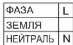
Brown conductor
Yellow-green conductor, blue conductor
Cable
Power
I CLASS PROTECTION AGAINST CURRENT LEAKAGE.
The electrical connection of the household appliance must be made using a separating device in accordance with the current rules and standards for electrical safety.
If the appliance is supplied without a power cable with plug, or without other devices for connection to the electrical network, with all poles disconnected, which ensures complete disconnection of the appliance from the electrical network in case of overvoltage, the connection must be made through a separating device with fixed electrical wiring, installed in accordance with the rules for laying electrical wiring.
2.2. CONNECTION TO THE GAS SUPPLY LINE
These instructions are intended for specialists with sufficient qualifications to perform the installation of equipment in accordance with the requirements of national rules and standards.
Only for the United Kingdom. According to the law, installation/commissioning must be carried out only by a "Gas Safe" service employee.
All work must be carried out by a qualified electrician.
The rating plate fixed on the hob indicates the type of gas for which the hob must operate. Before connecting the hob to the gas supply line or to the gas cylinder, it is necessary to check that the hob is adjusted for the type of gas that will be supplied to it. If the hob is not adjusted and the type of gas is needed, refer to the instructions given in the following paragraphs, where it is described how to change the adjustments.
When operating on liquefied gas (gas in a cylinder), use a pressure regulator that meets the requirements of national standards.
Pipes, washers, and sealing gaskets must comply with the requirements of national standards.
Some models are supplied with a fitting (adapter) with a conical thread. In some countries, the use of such adapters is mandatory. Fig. 8 shows how to distinguish an adapter with a cylindrical thread from an adapter with a conical thread (CY = cylindrical, CO = conical). In any case, the cylindrical thread must be
In any case, the end of the adapter with a cylindrical thread must be connected to the hob.
If the connection of the hob to the gas supply line is made using a flexible hose, check that the length of the flexible hose does not exceed 2 m.
The pipe should be installed in such a way that it does not come into contact with the upper parts of the furniture (for example, a shelf) and does not bend in places where it could be pinched. To avoid damaging the burner surface, perform its installation as described (see Fig. 6).
1) Connect the tee as shown in the figure:
A) Adapter with external thread 1/2"
B) Gasket 1/2"
C) Gas adapter with internal thread 1/2", conical, cylindrical, or cylindrical.
2) Tighten the connection with wrenches. Before tightening the connection, set the pipes in the required position.
3) Connect the hose to the gas line using rigid pipes or flexible hoses.
IMPORTANT NOTE: After connection and before the burner surface is used, check for gas leaks in all pipe connections using soapy water. NEVER USE A FLAME TO CHECK FOR GAS LEAKS. Also check that the flexible hose does not come into contact with the moving parts of the furniture (e.g., drawers) and does not pass through a place where it could be damaged.
Warning: If you smell gas near the burner surface, close the gas valve on the burner surface and call a qualified technician. Do not use a naked flame to locate gas leaks.
2.3. ADAPTING THE BURNER SURFACE TO OTHER TYPES OF GAS
To adapt the burner surface to other types of gas, perform the following instructions:
Remove the burner caps
Insert a flathead screwdriver (7 mm) into the base of the burner (Fig. 7), remove the nozzle and replace it with a nozzle corresponding to the type of gas that will be used (see the table of gas types).
2.4. ADJUSTING THE MINIMUM FLAME
To ignite the burner, set the flame height control knob to the minimum position, then press the control knob and apply slight pressure.
The minimum flame adjustment is made using the small screw, as shown in the figure. Turning the screw clockwise reduces the gas flow, while turning it counterclockwise increases the gas flow. Use this adjustment to obtain a flame height of 3-4 mm, then set the knob to the minimum position.
If liquefied petroleum gas (LPG) is used, turn the screw fully clockwise.
After performing the adjustments for the cooking surface for another type of gas, replace the old plate attached to the cooking surface, which indicates the type of gas, with a new one (supplied with the cooking surface) that indicates the type of gas for which the cooking surface has been adjusted.
3. INSTRUCTIONS FOR USE OF THE COOKING SURFACE
This electrical appliance is intended solely for use in accordance with its intended purpose, that is, for cooking in domestic conditions. Any other use of the cooking surface is considered improper and may be dangerous. The manufacturer is not responsible for damage or losses resulting from improper use of the cooking surface.
Before using the burner, ensure that the outer edges of the grate are positioned centrally relative to the burner, as shown in the figure below. If you use wok grates, the position is indicated on the grate. Ensure that the corresponding grate is used in the correct position.
3.1. USING THE GAS BURNER
To light the burner, bring a lit match to it, press the flame height control knob, and turn it counterclockwise.
If the burner has not been used for two or more days, before lighting it, wait a few seconds to allow air to escape from the tubes.
To light the burner of the cooking surface equipped with an electric ignition device, perform the following operations: press the flame height control knob and turn it counterclockwise to the position marked with the ignition symbol.
Light the burner using the ignition button. If the cooking surface is equipped with an automatic electric ignition, simply press the flame height control knob and set it to the position marked with the ignition symbol. The ignition system will generate sparks continuously until the flame height control knob is released from the ignition position.
If the burner does not ignite within 5 seconds, set the control knob to position 0 and repeat the operation described above.
In models equipped with a safety valve that automatically shuts off the gas supply in case of accidental flame extinction, the burners are lit as described above, but after lighting the burner, caution must be exercised.
Before switching on the gas cooking surface, check that the burners and burner caps are correctly positioned on the cooking surface.
If the device is not heating, you should use the lock to secure the knob; - Find the knob and turn it counterclockwise to the lock symbol; - Press and hold the button, lock the burner with the lock and hold the button pressed for 5 seconds after locking.
USEFUL TIPS
For best results, use pans and frying pans with a flat bottom, the size of which corresponds to the size of the gas burners (see table A).
| Тик конфорки | Ø skовордь/ kastroduл (cm) | Мошисть ( ) | G20/20 мбар кВТ(Метан) | G30/28-30 мбар (CHГ) |
| AUX Маленьая конфорka | 12 - 18 | 1,00 | 95 п/чac | 73 п/чac |
| SR Пolyбъстраз конфорka | 18 - 22 | 1,75 | 167 п/чac | 127 п/чac |
| R Бъстраз конфорka | 24 - 26 | 2,70 | 257 п/чac | 196 п/чac |
| UR ульта конфорka | 26 - 28 | 3,50 | 334 п/чac | 254 п/чac |
| DC 4 kW MONO | 26 - 28 | 4,00 | 381 п/чac | 291 п/чac |
Table
When using a pan or frying pan of a smaller size, the flame should be adjusted so that it does not extend beyond the bottom of the pan or frying pan. Do not use cookware with a concave or convex bottom.
WARNING: If the flame goes out accidentally, set the control knob to the off position and do not attempt to relight it for at least one minute.
If after some time of operation the gas taps on the hob become stiff to turn, they must be lubricated. This work must be carried out only by a qualified service technician.
4. MAINTENANCE AND CLEANING
Before cleaning the hob, check that it is cold. Unplug the appliance from the power supply (if the hob is electric) and switch off the power supply. Cleaning and maintenance of the household appliance must not be carried out by children without adult supervision. It is forbidden to use abrasive or corrosive cleaning agents, bleaching agents, or acids. Do not use scouring pads made of metal or coated with metal, as well as stainless steel parts with acids or acidic substances (lemon juice, vinegar, etc.).
Cleaning of enamelled, lacquered and chrome-plated surfaces must be carried out with soapy water or a neutral detergent. For cleaning stainless steel surfaces, it is necessary to use a suitable cleaning solution.
The burners can be cleaned with soapy water. To restore their original shine, use a household cleaner for stainless steel. After cleaning, dry the parts and put them back in place. Make sure that the burners are assembled correctly.
Chrome-plated grates and burners
Chrome-plated grates and burners darken over time. This is a normal and inevitable phenomenon that does not negatively affect the operation of the hob. You can purchase spare parts from the after-sales service department of our company.
5. AFTER-SALES SERVICE
Before calling a technical service specialist or carrying out repairs on the hob, perform the following checks:
- Make sure that the appliance plug is correctly inserted into the electrical outlet and that the fuse is not blown.
- Check the gas supply.
If you cannot determine the cause of the malfunction yourself:
Turn off the appliance and contact the after-sales service center. DO NOT attempt to repair the appliance yourself. The serial number consists of 16 digits. The first 8 digits are the model code. The next 4 digits are the production date (year, week). The last 4 digits are the factory number.
6. ENVIRONMENTAL PROTECTION
This appliance is marked in accordance with European Directive 2012/19/EC on waste electrical and electronic equipment (WEEE). Waste electrical and electronic equipment contains hazardous substances (which can negatively affect the environment) and basic components (which are subject to reuse). It is important that
waste electrical and electronic equipment is subjected to special treatment to remove and neutralize all hazardous substances, as well as to regenerate and reuse all materials. Every user can make a significant contribution to preventing environmental problems caused by waste electrical and electronic equipment; for this it is important to follow some basic rules:
- Do not dispose of waste electrical and electronic equipment as unsorted municipal waste.
- Waste electrical and electronic equipment should be handed over to collection points controlled by local authorities or registered companies. In many countries, for large quantities of waste electrical and electronic equipment, waste collection is carried out at home.
- When purchasing a new appliance, the old appliance can be returned to the retailer, which is obliged to accept it free of charge on a one-for-one basis, if the appliances are of similar type and the returned appliance has the same functions as the one being sold.
Declaration of Conformity: This equipment, parts of which come into contact with food, complies with the requirements of European Directive 89/109/EEC.
The device complies with European Union Directive 2009/142/EC (GAD), and from 21/04/2018 - with the Gas Appliances Regulation 2016/426 (GAR).
By placing the marking on this product, we declare our sole responsibility for compliance with all European safety, health, and environmental requirements set out in the legislation for this product.
The manufacturer is not responsible for errors or omissions that may appear in this instruction. We reserve the right to make changes to the design of our products to improve the quality of the products we produce. When making such changes, the functions of the product and its safety will remain unchanged.

This product complies with the technical regulations of the Customs Union: - TR CU 004/2011 "On Safety of Low-Voltage Equipment" - TR CU 016/2011 "On Safety of Appliances Operating on Gaseous Fuel" - TR CU 020/2011 "Electromagnetic Compatibility of Technical Means"
| Плacrпна рорелки | 3 Gas | 4 Gas | 4 Gas | 5 Gas | 5 Gas | 5 Gas |
| рорелka | Aux/R/DC 4 Mono | Aux/SR/R/DC 4 Mono | Aux/SR/R | UR/2R/SR/AUX | DC/2R/SR/AUX | DC/R/2SR/AUX |
| Тип | UH60MF | UH60MF | UH60MF | UH75MF | UH75MF | UH75MF |
| FFD | ДА | ДА | ДА | ДА | ДА | ДА |
| Aux 1kW | 1 | 1 | 1 | 1 | 1 | 1 |
| Sr 1,75 kW | - | 1 | 1 | 1 | 1 | 2 |
| R 2,7 kW | 1 | 1 | 1 | 2 | 2 | 1 |
| UR 3,5 kW | - | - | - | 1 | - | - |
| Dc 4 kW Mono | 1 | 1 | - | - | 1 | 1 |
| Номиналыньий в��д телда | 7,7 kW | 9,45 kW | 7,2 kW | 11,65 kW | 12,15 kW | 11,2 kW |
| G20/20 mbar | 734 l/h | 900 l/h | 686 l/h | 1110 l/h | 1157 l/h | 1067 l/h |
| G30/28-30 mbar | 560 g/h | 688 g/h | 524 g/h | 848 g/h | 884 g/h | 815 g/h |
| Клас установки | 3 | 3 | 3 | 3 | 3 | 3 |
| Нароженце/Частota B/Гц | 220-240 V/ 50-60 Hz | 220-240 V/ 50-60 Hz | 220-240 V/ 50-60 Hz | 220-240 V/ 50-60 Hz | 220-240 V/ 50-60 Hz | 220-240 V/ 50-60 Hz |
| Вхочая заektриеска мошноctь | 1 | 1 | 1 | 1 | 1 | 1 |
| Злестоюдиг | ДА | ДА | ДА | ДА | ДА | ДА |
| Размеры варочи поberхости | 595x510 | 595x510 | 595x510 | 745x510 | 745x510 | 745x510 |
This product is intended for household use only.
INSTRUCTIONS FOR SAFE USE
Efficiency Declaration 2016/426
| DIAMOND (L1) BIG REAR | (L3,L5) BIG FRONT (L2) | ||||||||||
| SINGLE BURNER EFFICIENCY | SINGLE BURNER EFFICIENCY | SINGLE BURNER EFFICIENCY | |||||||||
| AUX | SR | R | DC | AUX | SR | R | DC | AUX | SR | R | DC |
| - | 55% | 55,90% | 55,90% | - | 57,10% | 55,90% | 54,30% | - | 60% | 55,90% | 54,30% |
| MEDIUM %55,6 | MEDIUM %55,8 | MEDIUM %56,7 | |||||||||
| 75 CENTER UR (L6) 75 CEN | ITER DC (L7) 75 LATERAL DC (L8) | ||||||||||
| SINGLE BURNER EFFICIENCY | SINGLE BURNER EFFICIENCY | SINGLE BURNER EFFICIENCY | |||||||||
| AUX | SR | R | UR | AUX | SR | R | UR | AUX | SR | R | UR |
| - | 57,10% | 57,60% | 55,90% | - | 57,10% | 57,60% | 55,90% | - | 60% | 59,40% | 57,60% |
| MEDIUM %57,1 | MEDIUM %56,9 | MEDIUM %59,3 | |||||||||

GB-IE
The manufacturer will not be responsible for any inaccuracy resulting from printing or transcript errors contained in this brochure. We reserve the right to carry out modifications to products as required, including the interests of consumption, without prejudice to the characteristics relating to safety or function.
FR
- INSTRUCTIONS FOR USE AND INSTALLATION
- COOKING HOB
- HOB
- CONTENT
- GB-IE
- CONTENTS
- CZ
- ES
- INSTRUCTIONS FOR THE INSTALLER
- BUILDING IN
- SUITABLE LOCATION
- ELECTRICAL CONNECTION (FOR U.K. ONLY)
- WARNING - THIS APPLIANCE MUST BE EARTHED
- ELECTRICAL CONNECTION
- GAS CONNECTION
- ADAPTING THE HOB TO DIFFERENT TYPES OF GAS
- REGULATING THE MINIMUM FLAME
- USE OF HOB - USER INSTRUCTIONS
- GENERAL ADVICE
- MAINTENANCE AND CLEANING
- AFTERCARE
- PROTECTION OF THE ENVIRONMENT
- SAFETY INSTRUCTIONS
- SUITABLE INSTALLATION LOCATION
- CANDY
- WARRANTY CERTIFICATE
- BUILT-IN HOB
- INSTALLATION INSTRUCTIONS
- BUILT-IN WORK SURFACES
- CHOOSING A LOCATION FOR INSTALLING THE WORK SURFACE
- CONNECTION TO THE ELECTRICAL SUPPLY (ONLY FOR BUILT-IN MODELS)
- CONNECT
- TO THE TERMINAL OF THE ELECTRICAL SUPPLY
- CONNECTION TO THE ELECTRICAL SUPPLY
- CONNECTION TO THE GAS SUPPLY LINE
- TO ADAPT THE BURNER SURFACE TO OTHER TYPES OF GAS, PERFORM THE FOLLOWING INSTRUCTIONS
- INSTRUCTIONS FOR USE OF THE COOKING SURFACE
- USING THE GAS BURNER
- USEFUL TIPS
- CHROME-PLATED GRATES AND BURNERS
- AFTER-SALES SERVICE
- ENVIRONMENTAL PROTECTION
- INSTRUCTIONS FOR SAFE USE
- FR
Brand : CANDY
Model : PCP2S5CHG6BRX
Category : Built-in oven