FPH 5114 TC BK - Range hood Fulgor Milano - Free user manual and instructions
Find the device manual for free FPH 5114 TC BK Fulgor Milano in PDF.



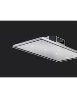
| Product type | Built-in worktop hood |
| Brand | Fulgor Milano |
| Model | FPH 5114 TC BK |
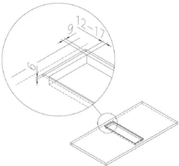
| Dimensions (W x D x H) | 490 x 126 mm (projecting installation) or 514-524 x 144 mm (flush installation) |
| Weight (estimated) | Approximately 10 kg |
| Power supply | 220-240 V ~ 50/60 Hz |
| Maximum motor power | 690 W |
| Control type | Digital touch control with display |
| Motor speeds | 4 speeds (adjustable by + and - keys) |
| Special functions | Delayed shut-off timer (10 min), metal filter cleaning indicator (100 h) |
| Lighting | Not specified (probably integrated LED) |
| Metal filters | Dishwasher-safe stainless steel grease filters |
| Charcoal filters (optional) | Models KFCP, KFCPR, KFCPC |
| Extraction mode | Recirculation (filtering) or external extraction (extracting) |
| Compatible cooking types | Induction or ceramic glass domino hobs (gas prohibited) |
| Installation | Reserved for a qualified technician |
| Maintenance | Monthly cleaning of metal filters, cleaning surfaces with a soft cloth and mild detergent |
| Safety | Mandatory disconnection before maintenance, mandatory grounding, do not use with gas appliances |
| Spare parts and repairability | Filters, power cable (type H05VV-F 3x0.75mm²) available from manufacturer or after-sales service |
| Environmental standard | Compliant with WEEE directive (2002/96/EC) |
Frequently Asked Questions - FPH 5114 TC BK Fulgor Milano
User questions about FPH 5114 TC BK Fulgor Milano
0 question about this device. Answer the ones you know or ask your own.
Ask a new question about this device
Download the instructions for your Range hood in PDF format for free! Find your manual FPH 5114 TC BK - Fulgor Milano and take your electronic device back in hand. On this page are published all the documents necessary for the use of your device. FPH 5114 TC BK by Fulgor Milano.
USER MANUAL FPH 5114 TC BK Fulgor Milano
natural_image
Modern kitchen with a black stovet and steaming steam, surrounded by fresh tomatoes and onions (no text or symbols visible)| IT | ISTRUZIONI PER L'USO, MANUTENZIONE E INSTALLAZIONE DELLA CAPPA |
| EN | INSTRUCTIONS FOR USING, MAINTAINING AND INSTALLING THE HOOD |
| DE | BEDIENUNGS-, WARTUNGS- UND INSTALLATIONSHANDBUCH ABZUGSHAUBE |
| FR | INSTRUCTIONS POUR L'UTILISATION, L'ENTRETIEN ET L'INSTALLATION DE LA HOTTE. |
| NL | HANDLEIDING VOOR HET GEBRUIK, HET ONDERHOUD EN DE INSTALLATIE VAN DE AFZUIGKAP |
| ES | INSTRUCCIONES PARA EL USO, MANTENIMIENTO E INSTALACION DE LA CAMPANA |
| CZ | NÁVOD K POUŽITÍ, ÚDRŽBĚ A INSTALACI STOLNÍ DIGESTOŘE |
EN This product complies with EU Directive 2002/96/EC.
The crossed bin symbol on the appliance indicates that the product, at the end of its life, must be disposed of separately from domestic waste, either by taking it to a separate waste disposal site for electric and electronic appliances or by returning it to your dealer when you buy another similar appliance. The user is responsible for taking the appliance to a special waste disposal site at the end of its life. If the disused appliance is collected correctly as separate waste, it can be recycled, treated and disposed of ecologically; this avoids a negative impact on both the environment and health, and contributes towards the recycling of the product's materials. For further information regarding the waste disposal services available, contact your local waste disposal agency or the shop where you bought the appliance.
natural_image
Isometric line drawing of a mechanical component with a square base and circular top (no text or symbols)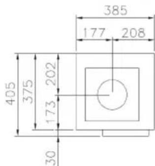
natural_image
Technical line drawing of a mechanical component with a magnified inset showing a detail labeled 'G' (no text or symbols beyond label)A = Cappa da piano
natural_image
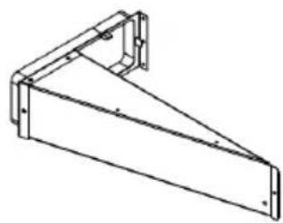
Technical line drawing of a metal bracket with mounting flanges (no text or symbols)B = Convogliatore
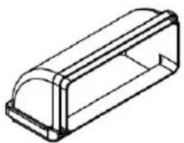
natural_image
Isometric line drawing of a rectangular electronic component with a curved top surface (no text or symbols)C = KT4
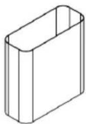
natural_image
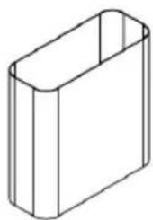
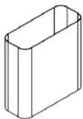
Simple line drawing of a rectangular box or container (no text or symbols)D = Tubo plastica 220x90x200
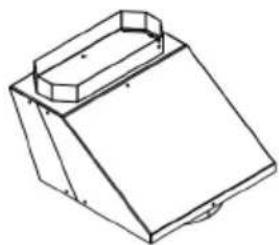
natural_image
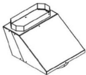
Isometric line drawing of a 3D mechanical part with a sloped top and rectangular base (no text or symbols)E = Disassatore
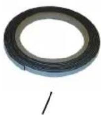
natural_image
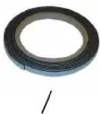
Circular black rubber tape with a single wire, no text or symbols visibleF
ALLACCIAMENTO ELETTRICO
natural_image
Pure electrical circuit lines without any symbolsUSO E MANUTENZIONE
natural_image
Two technical diagrams showing mechanical assembly with arrows indicating motion (no text or symbols)INSTRUCTIONS FOR USING, MAINTAINING AND INSTALLING THE HOOD
ATTENTION: The hood must only be installed by a qualified technician.
The company accepts no liability if it is installed by an unauthorised person.
Please read these instructions carefully before beginning the installation. Conserve this handbook together with the hood
WARNINGS
Before cleaning or performing any periodic or urgent maintenance to the hood, ensure the power is turned off by removing the plug from the socket and turning the main switch to 0 (off).
Do not connect the hood to any piping used for combustion appliances, such as burners, boilers or fireplaces.
Check that the main power supply corresponds to the voltage required by the hood, which is given on the silver label stuck inside the hood.
Ensure that the electric system is correctly earthed and that the earth discharge works correctly.
When cooking do not use any materials that could form high or unusual flames.
Oil that has been used twice and fats are very dangerous and could easily catch fire.
Do not prepare flambè dishes.
Attention: accessible parts may become hot when the downdraft is used with cooking appliances.
This appliance can be used by children aged from 8 years and above and persons with reduced physical, sensory or mental capabilities, or lack of experience and knowledge if they have been given supervision or instruction concerning use of the appliance in a safe way and understand the hazards involved.
Children shall not play with the appliance. Cleaning and user maintenance shall not be made by children without supervision.
Once the installation is complete, the electrical components (cables, connectors, motor and control box) will no longer be accessible to the user. To allow access to those parts place a removable panel secured with screws.
The cooking hood must only be used with the extraction unit supplied with it, as indicated by the manufacturer with a maximum output of 690W.
The device is only suitable for domestic use. We recommend that you turn the hood on a few minutes before use and turn off 10 minutes after use.
Respect local legislation and regulations issued by the relative authorities regarding the exhaust air when the suction is operating.
Failure to respect and perform all the maintenance and cleaning operations described in this handbook could cause a fire hazard.
Text, images and specifications correspond to the status of the appliance at the date of print. The appliance is subject to changes und further development.
INSTALLATION
The hood must be combined with domino hobs (induction or glass-ceramic). Combined operation with gas
hobs is not permissible and explicitly prohibited.
Once the installation is complete, the electrical components (cables, connectors, motor and control box) will no longer be accessible to the user. To allow access to those parts place a removable panel secured with screws.
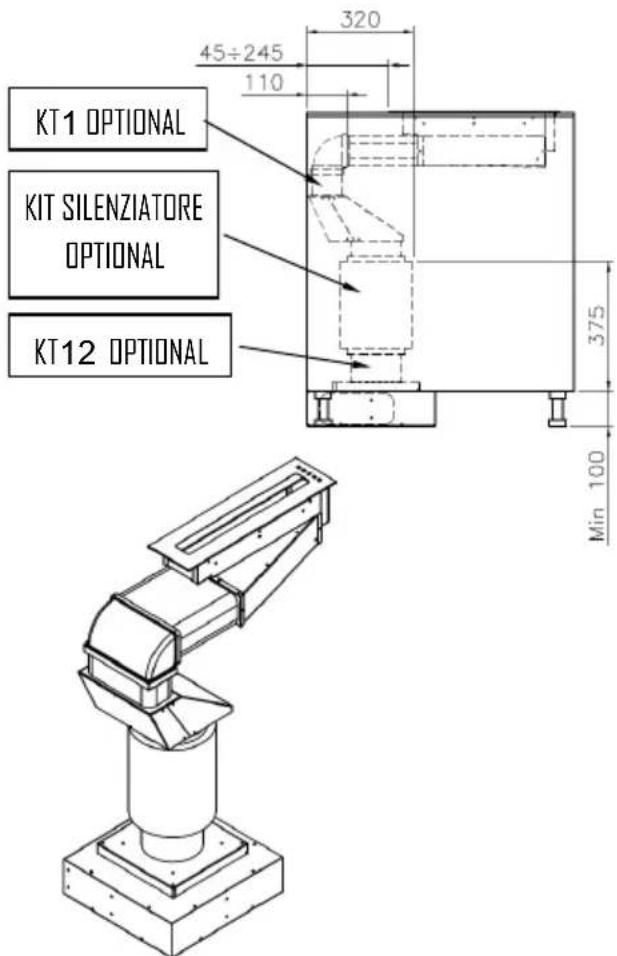
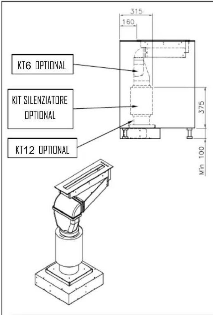
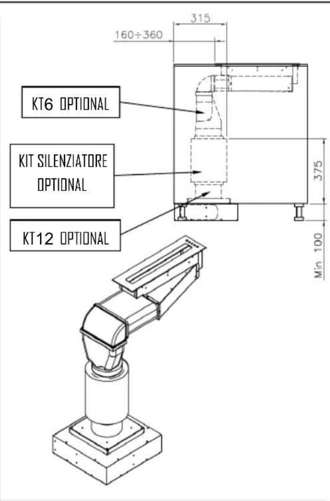
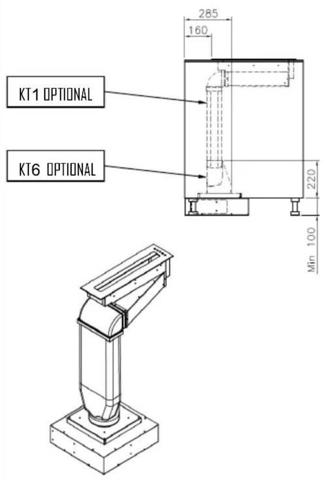
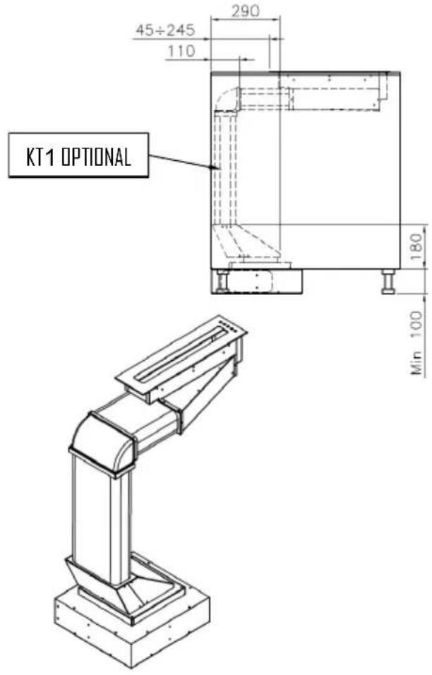
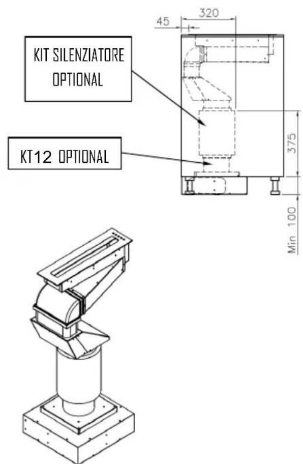
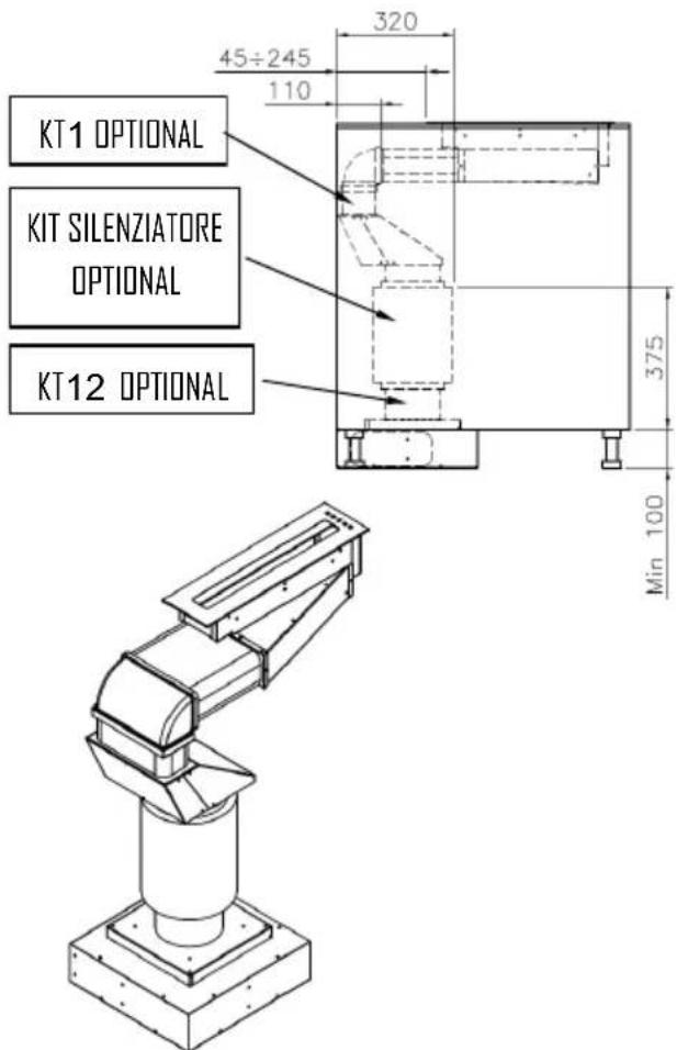
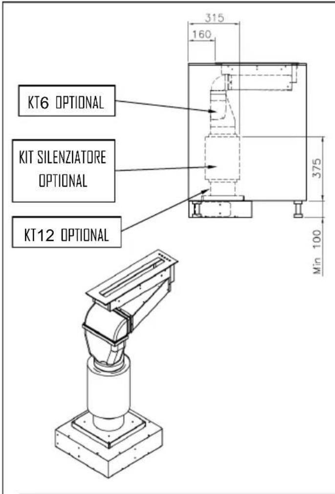
The hood can be used for both filtering and suction.
When the filtering function is operating, i.e. with air recycle, carbon filters must be used (refer to the paragraph on CARBON FILTERS).
When the suction function is operating, i.e. exhausting the filtered air on the outside, a suitable compensation system must be used according to current standards in force. The diameter of the fume exhaust pipe must be the same or greater than the diameter of the hood pipe union.
There must be sufficient ventilation in the room where the hood is installed, to allow the simultaneous use of other appliances that use gas or other fuel.
ASSEMBLY INSTRUCTIONS
The hood must be combined with domino hobs (induction or glass-ceramic). Combined operation with gas hobs is not permissible and explicitly prohibited.
EN-10
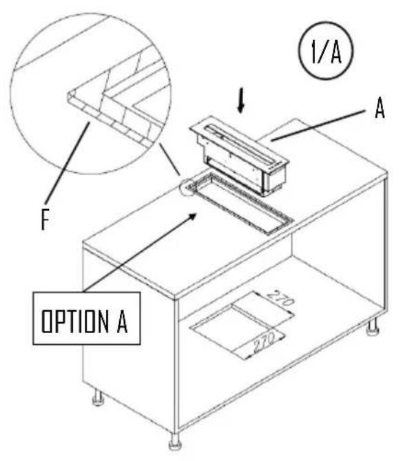
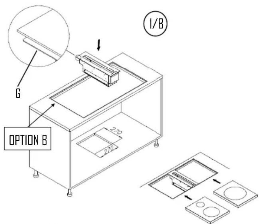
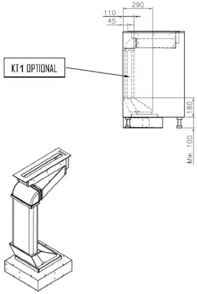
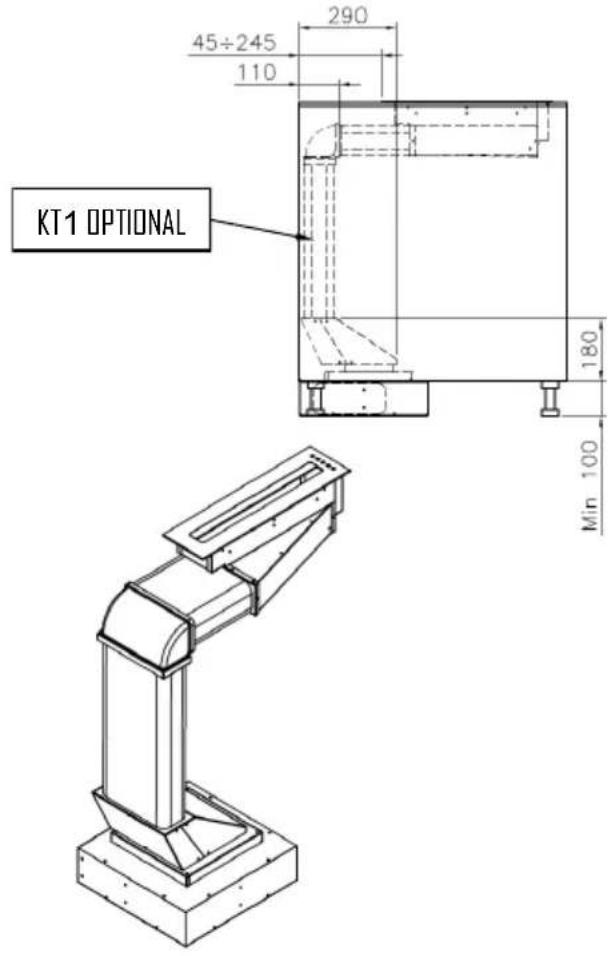
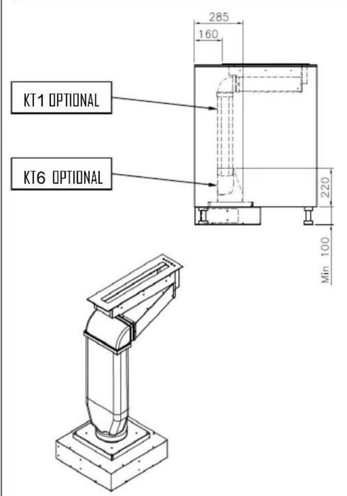
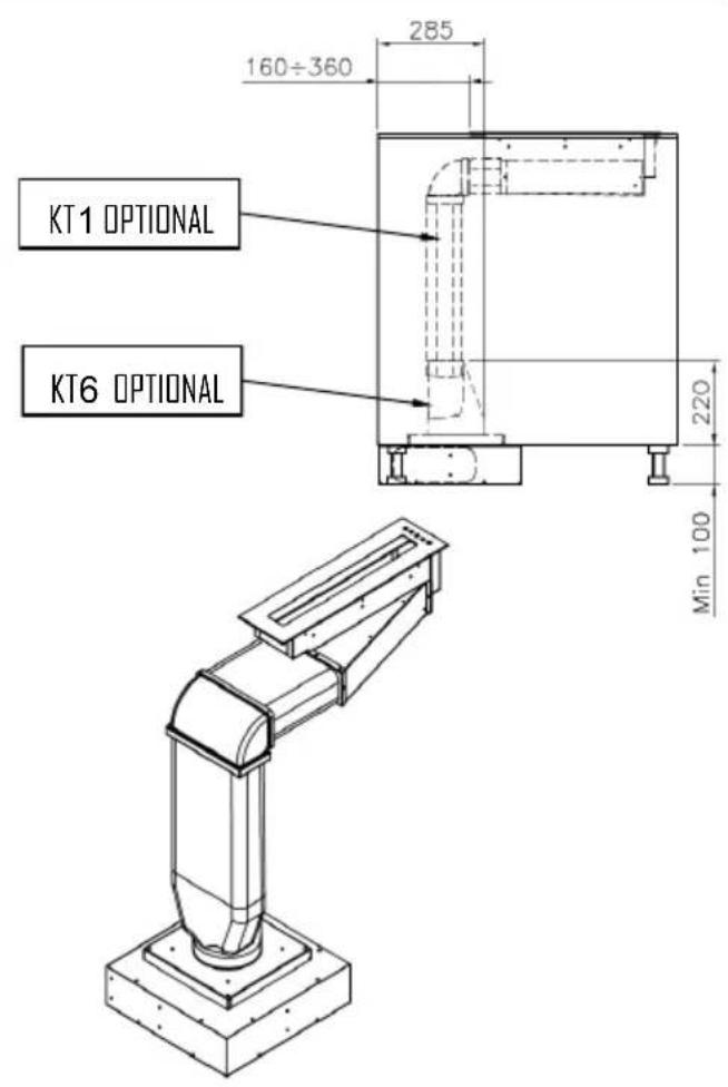
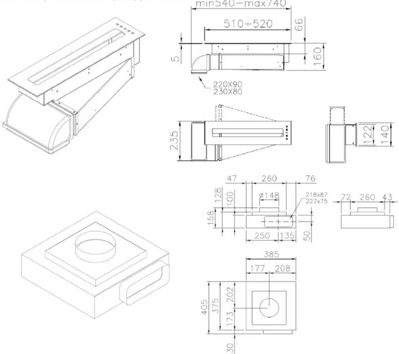
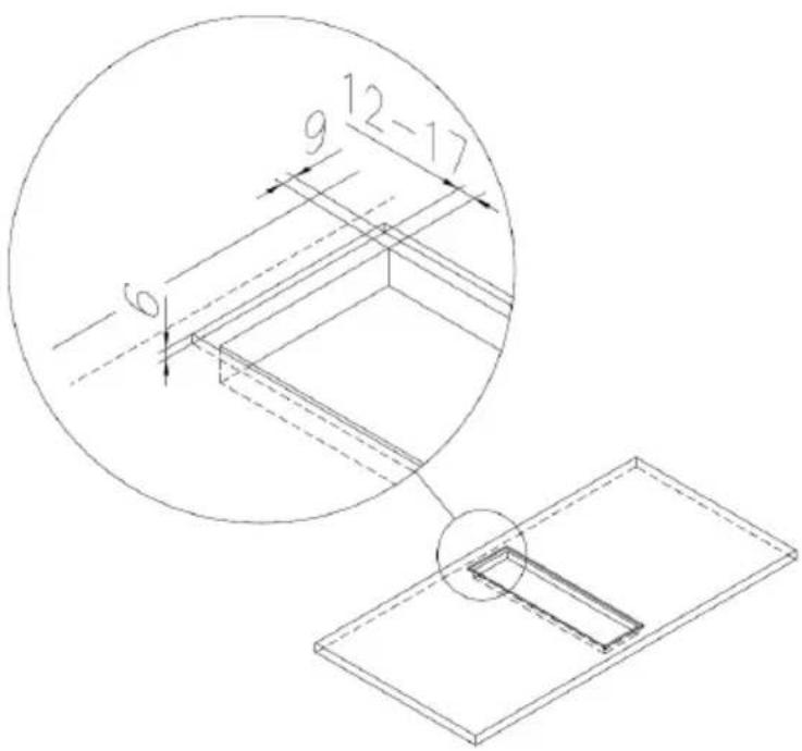
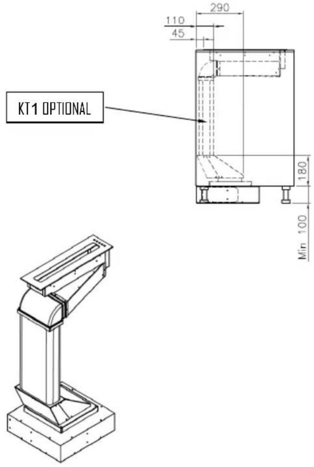
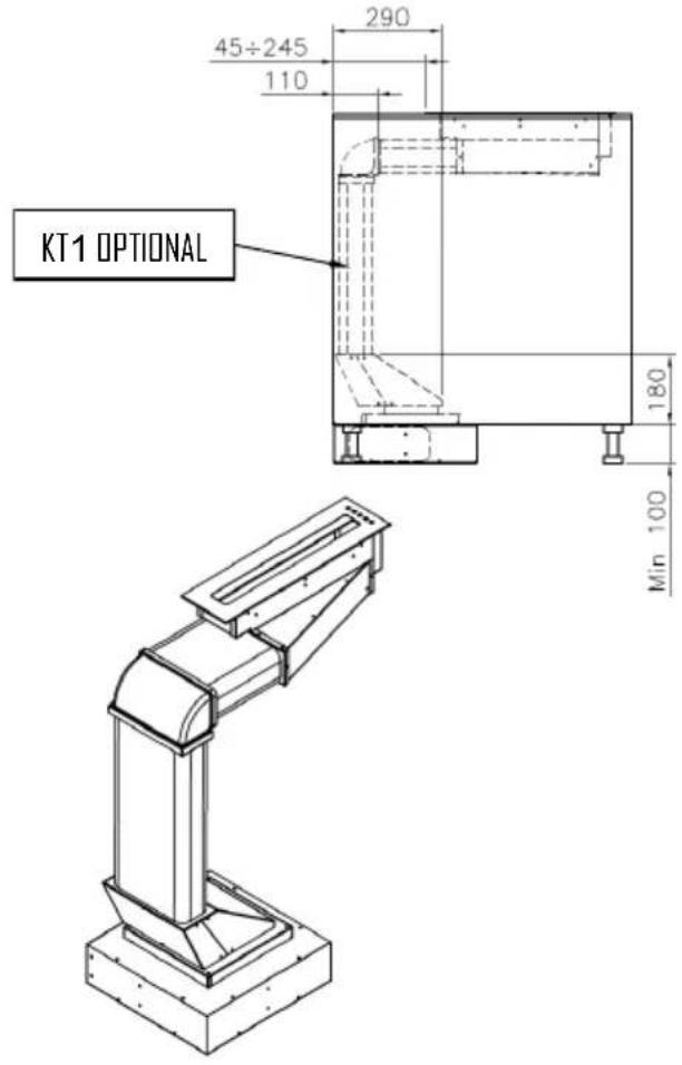
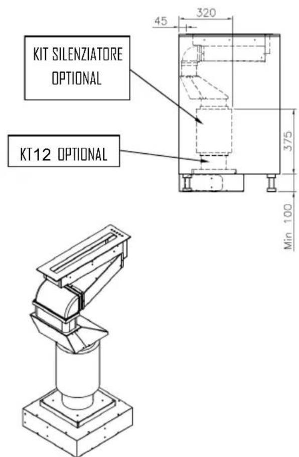
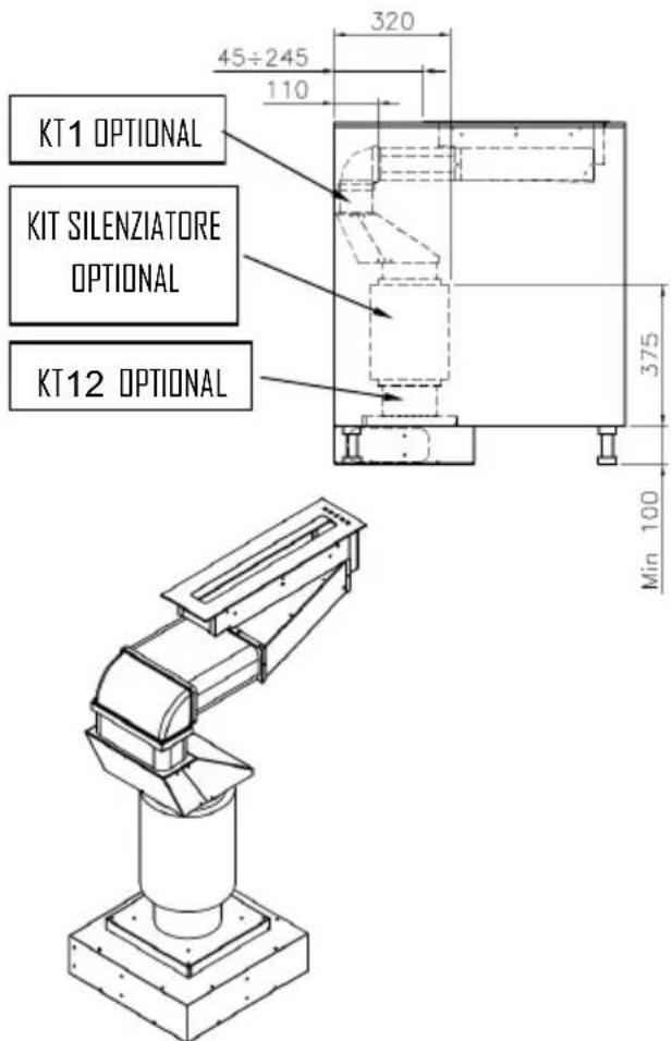
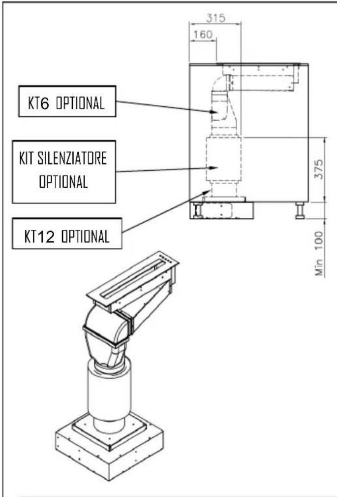
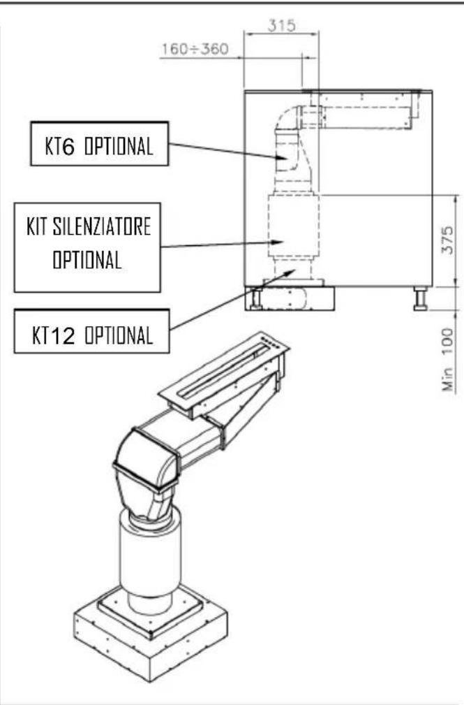
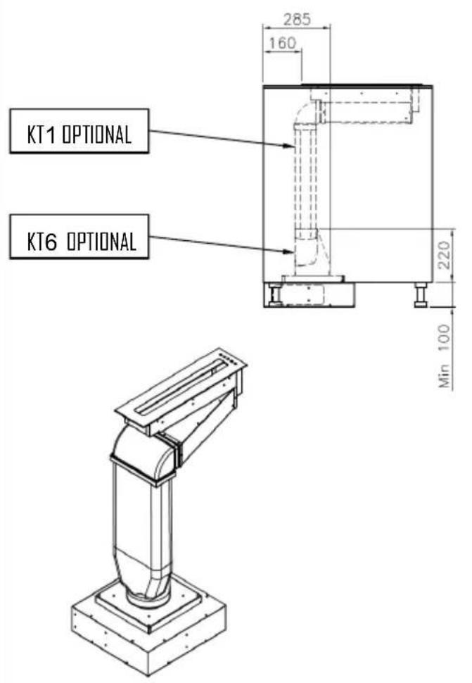
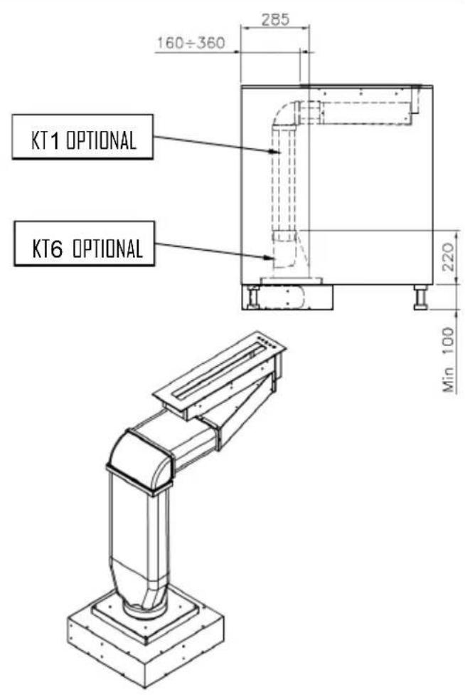
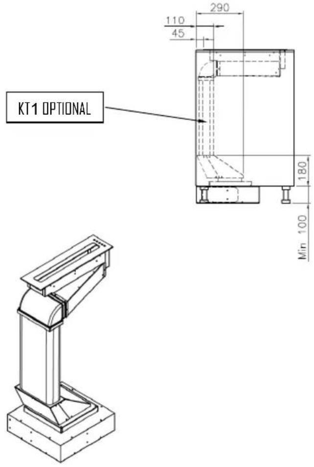
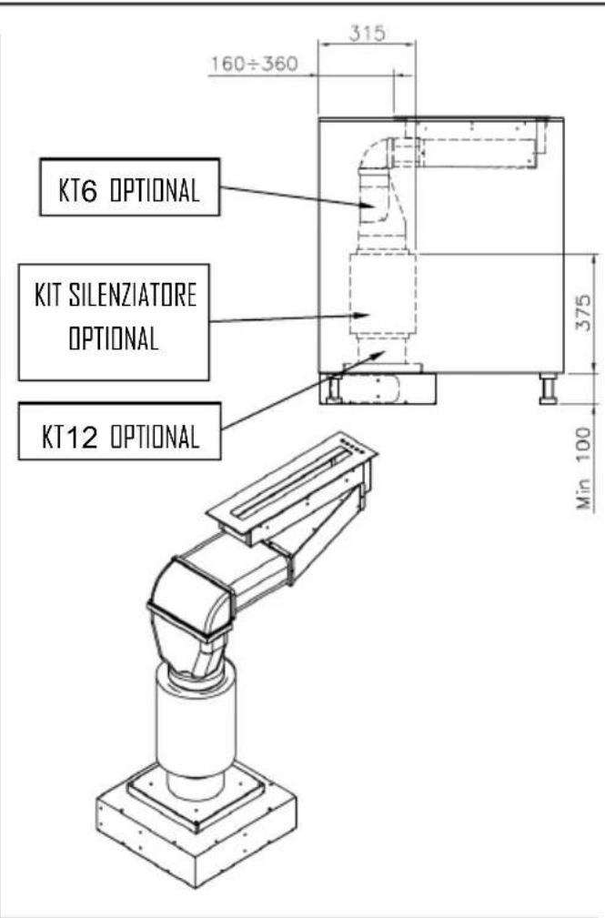
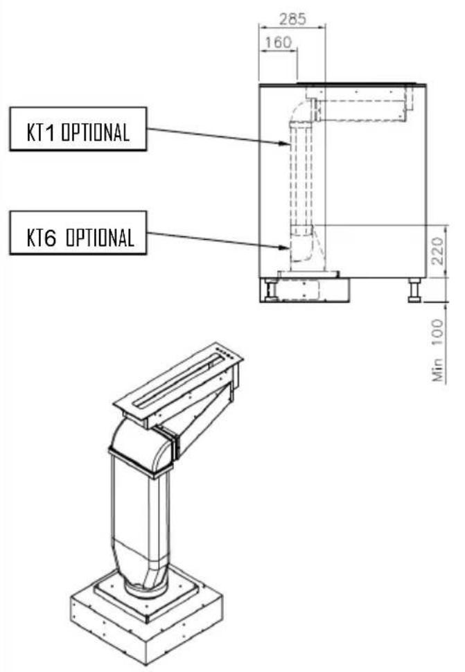
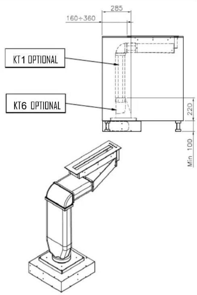
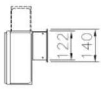
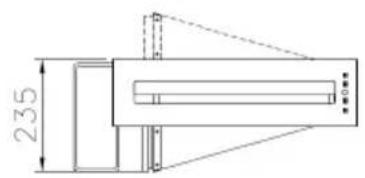
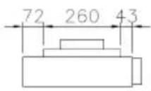
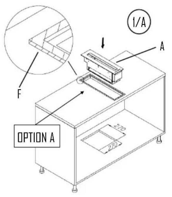
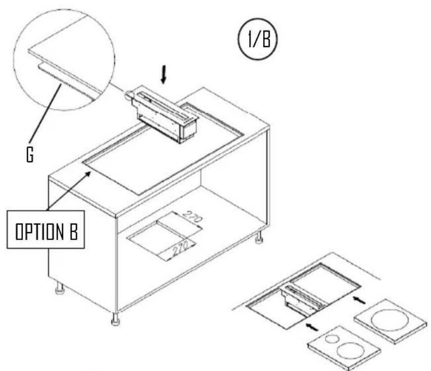
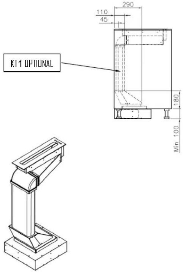
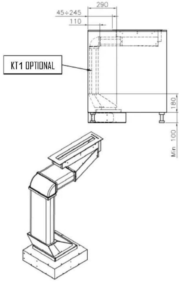
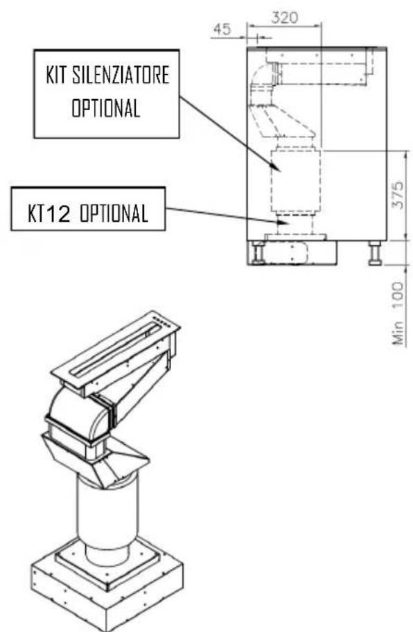
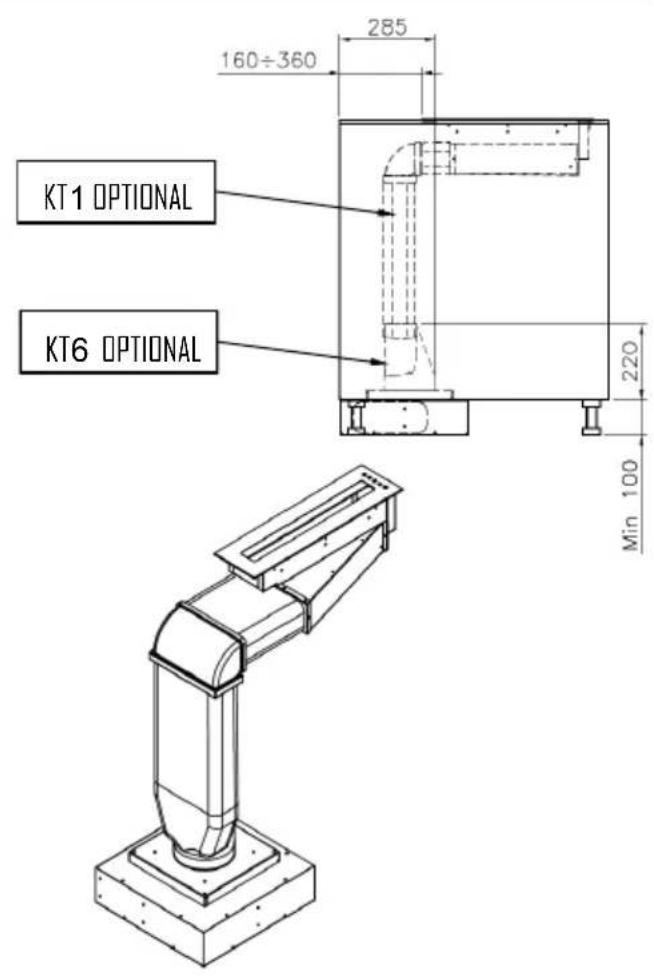
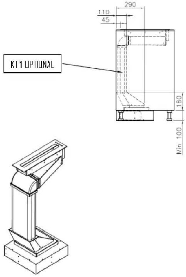
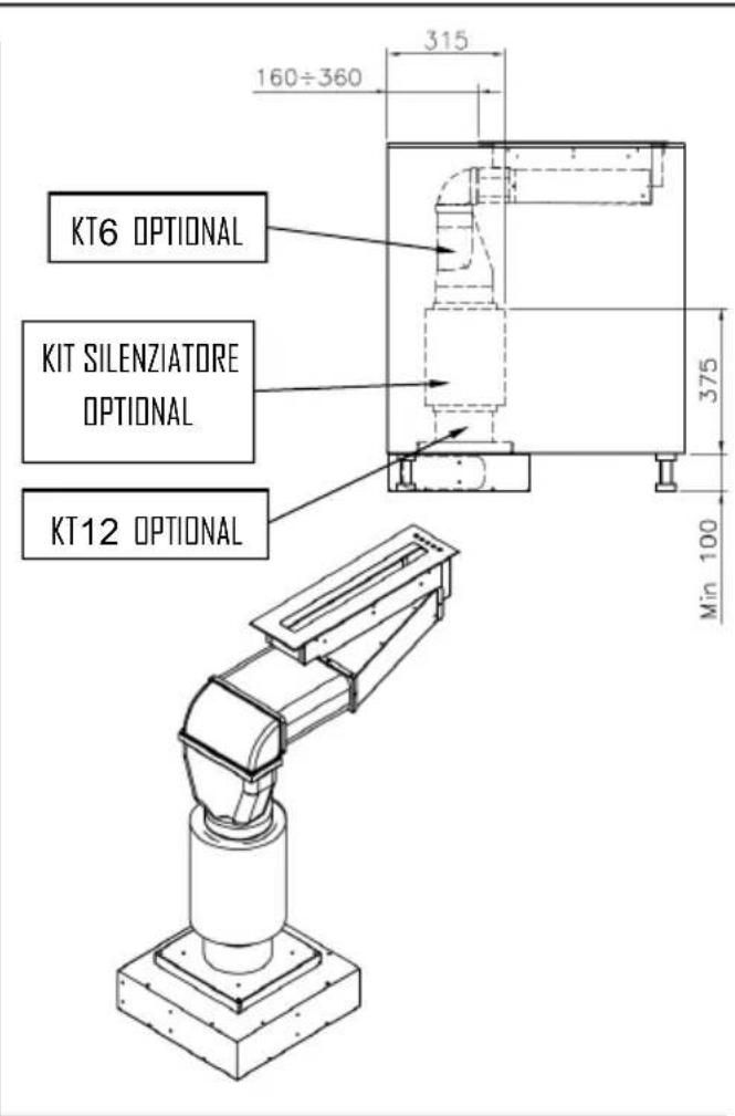
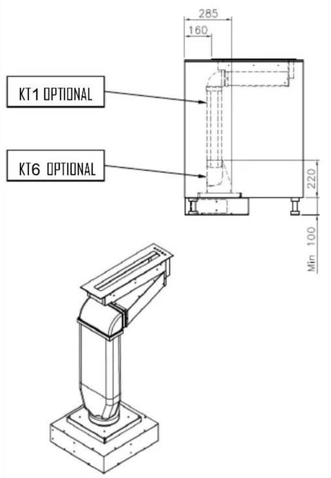
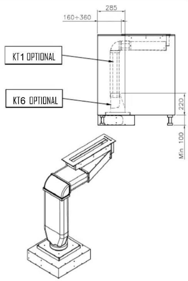
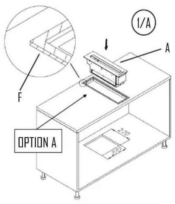
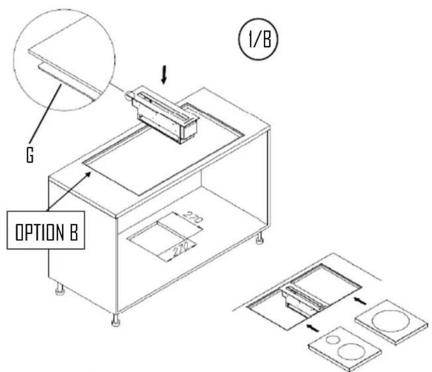
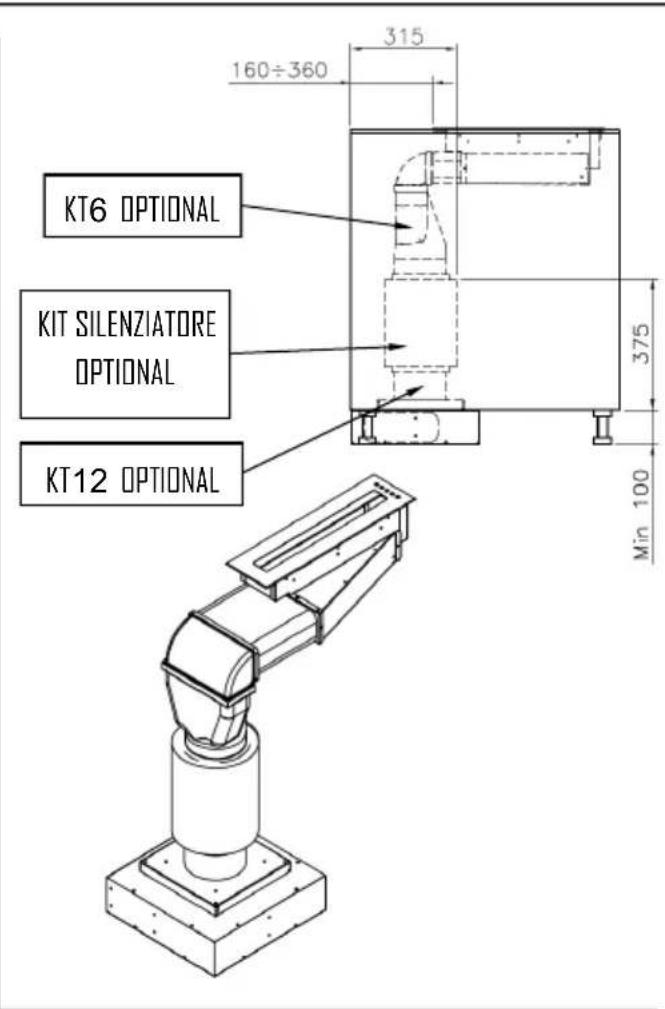
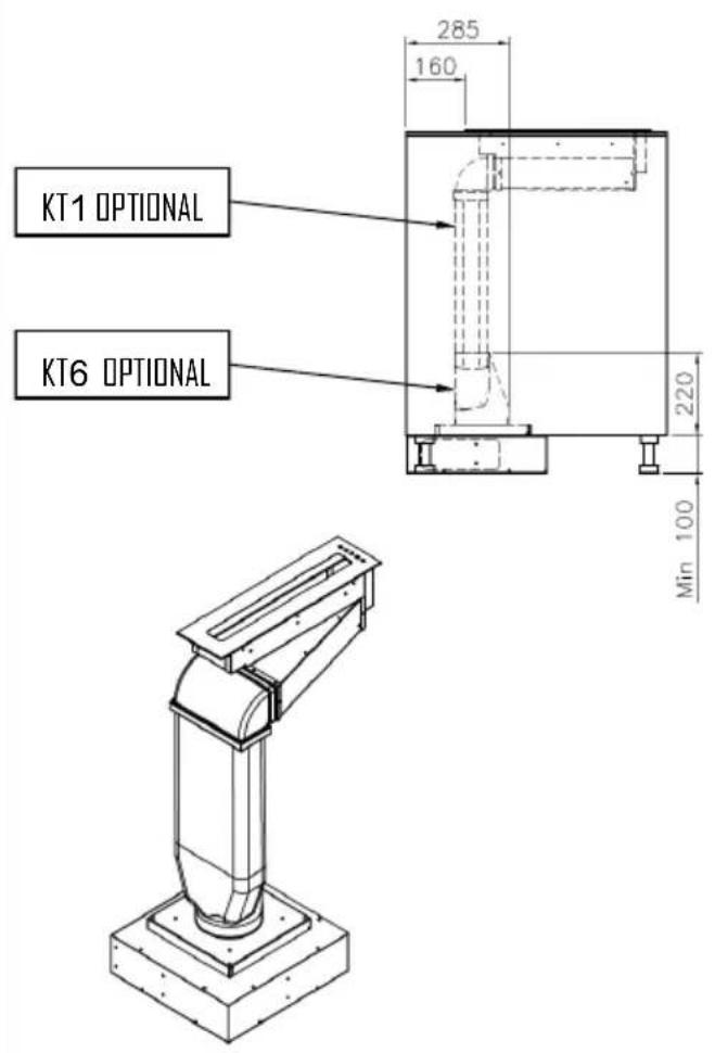
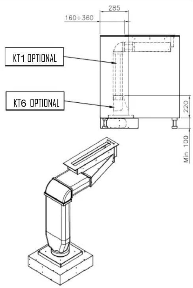
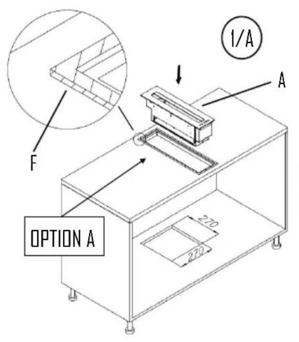
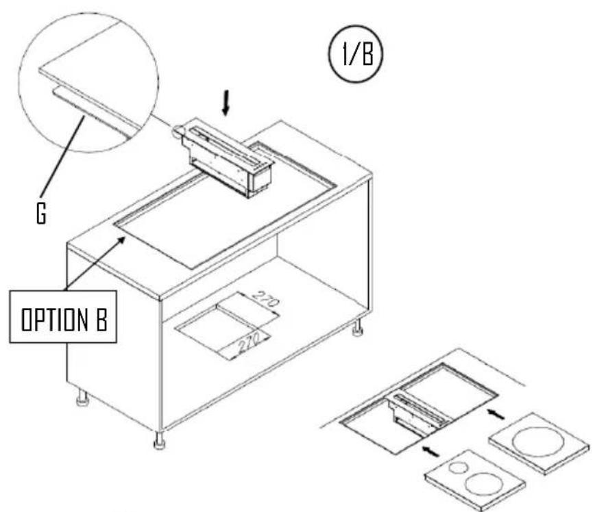
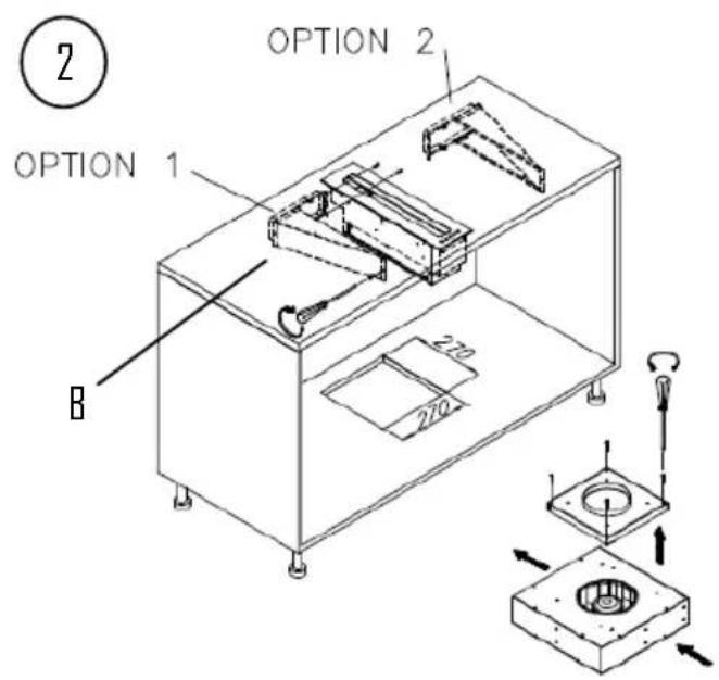
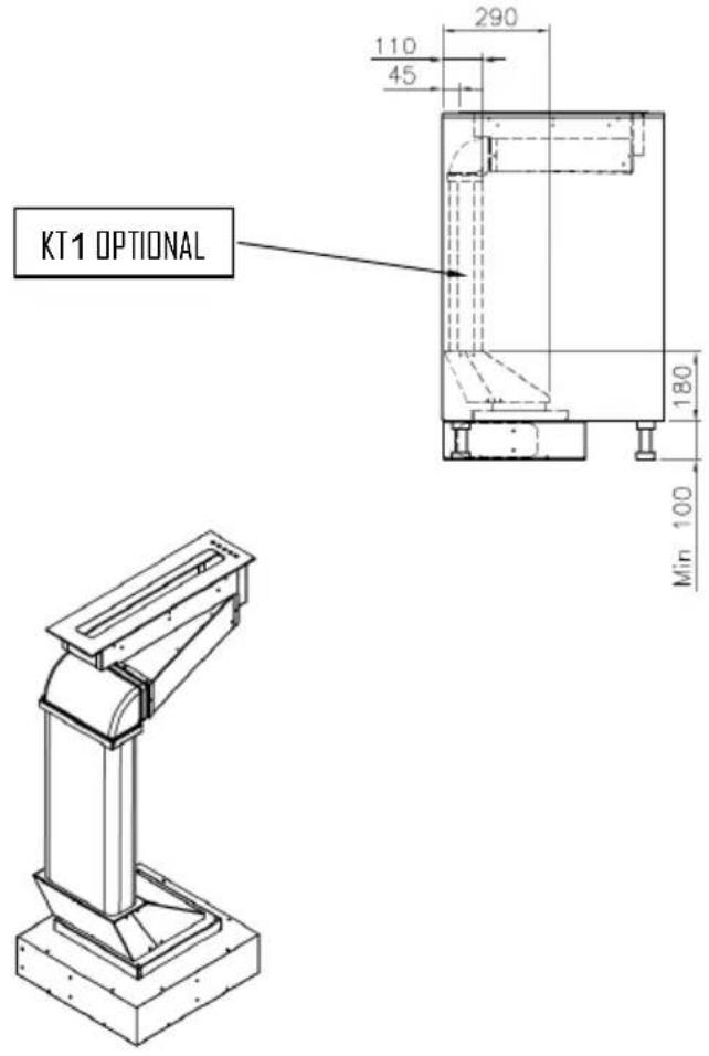
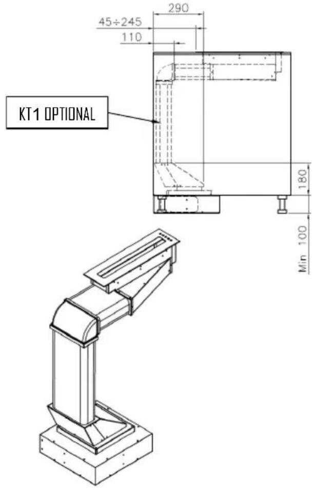
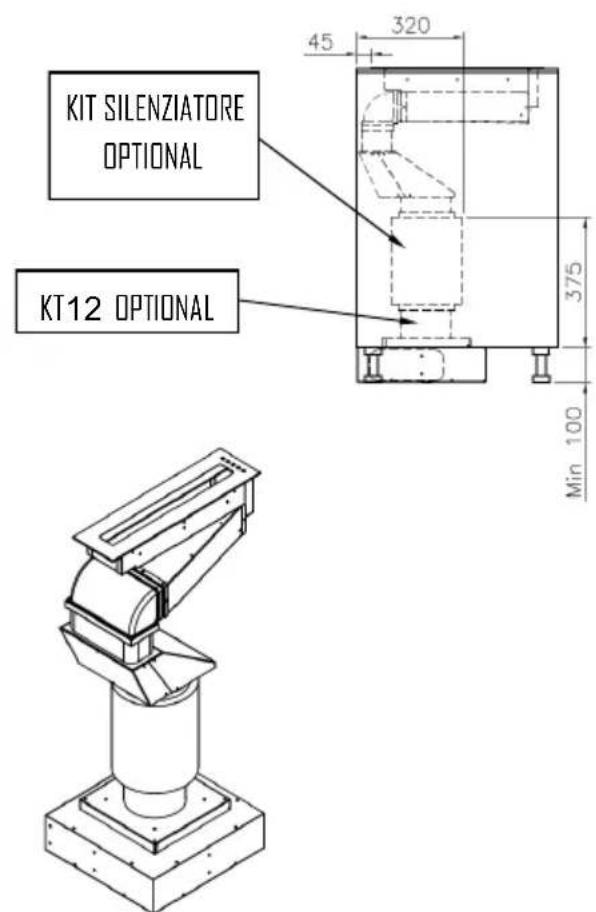
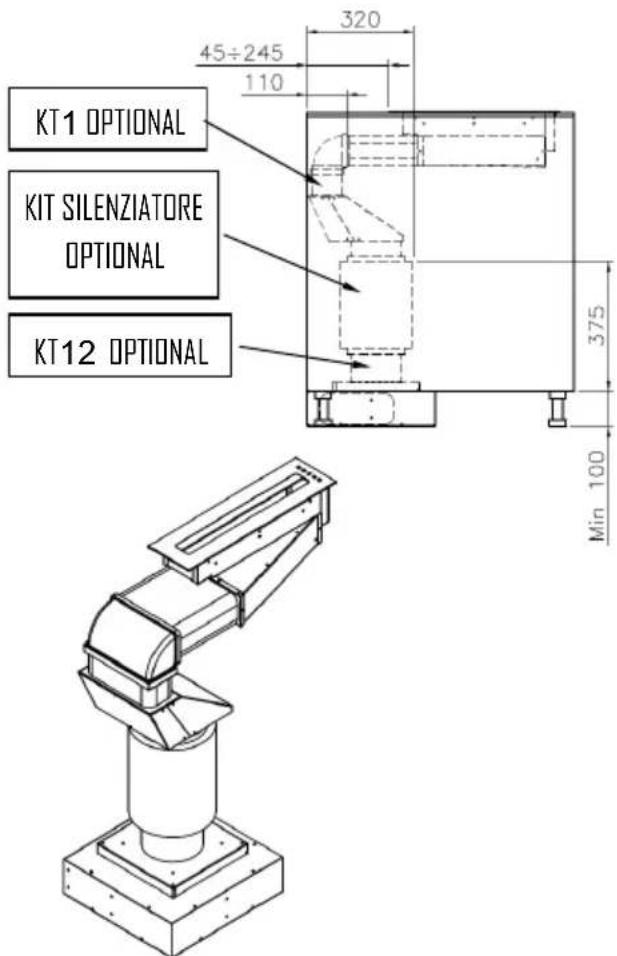
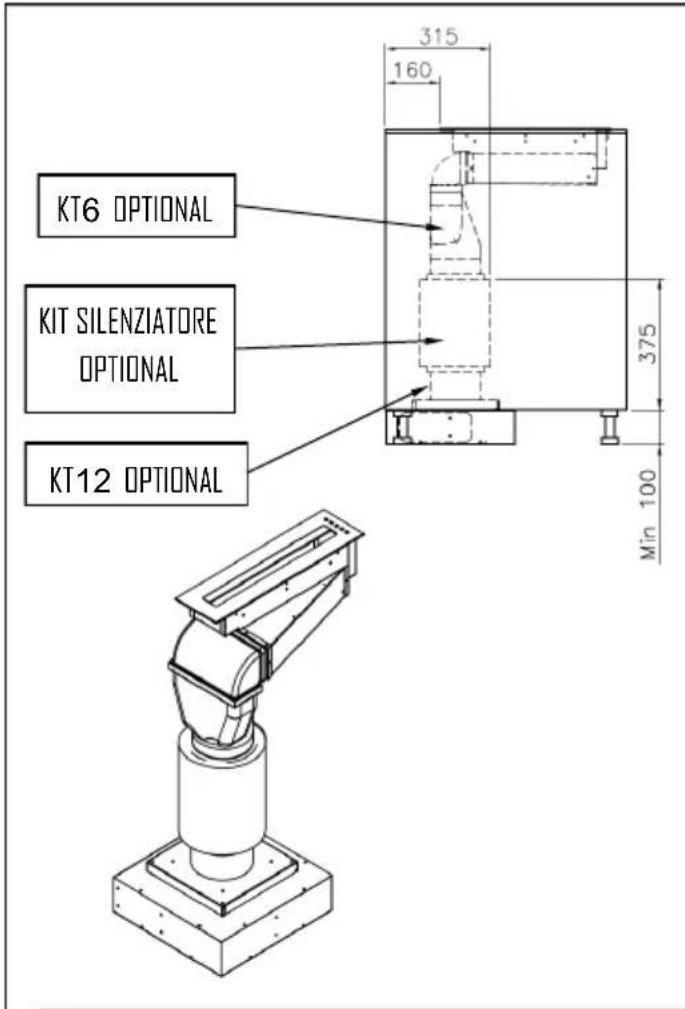
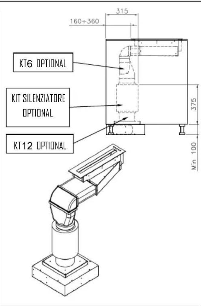
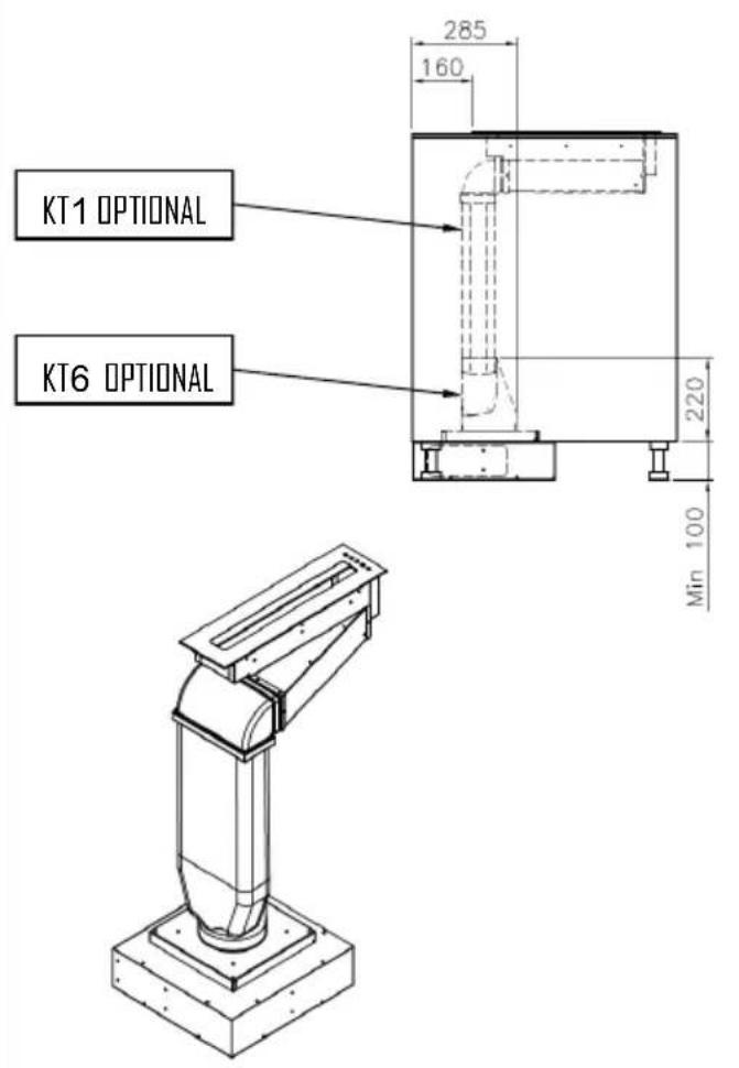
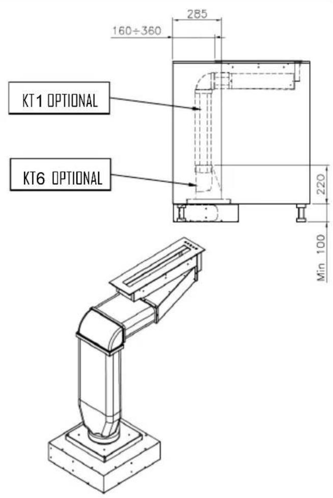
For the dimensions of the hole, see drawing here below.
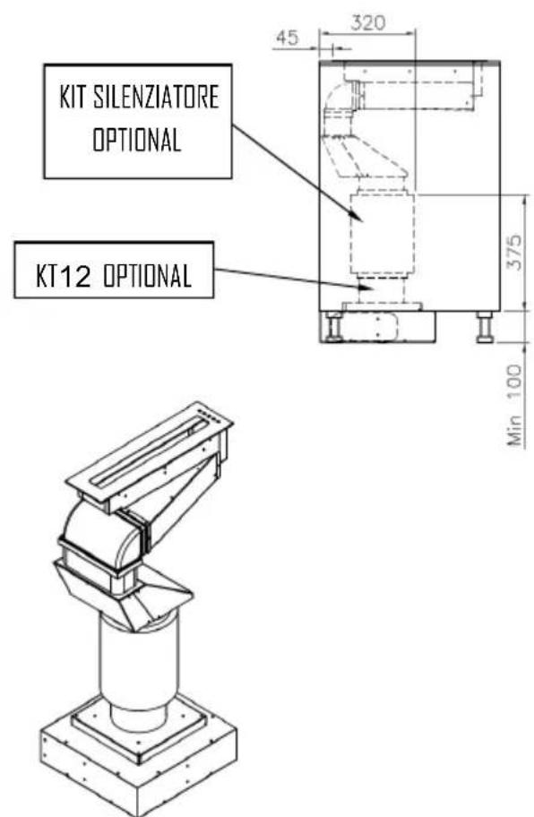
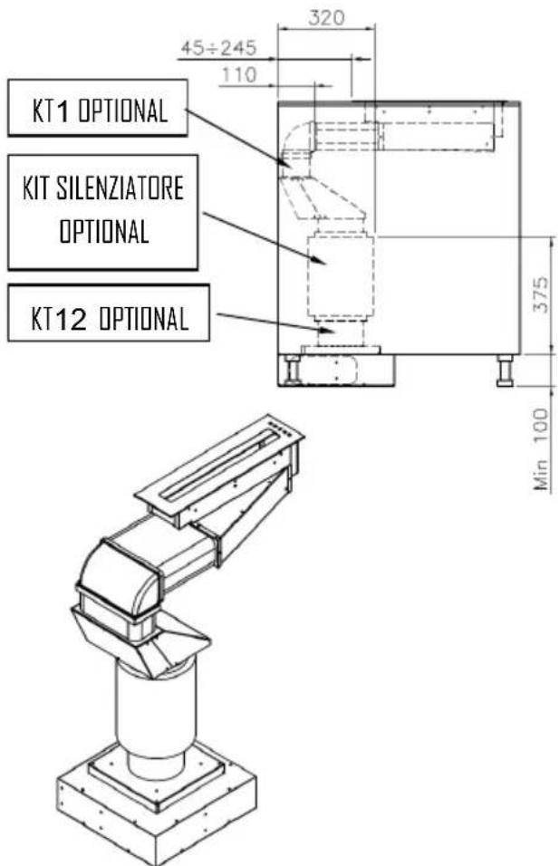
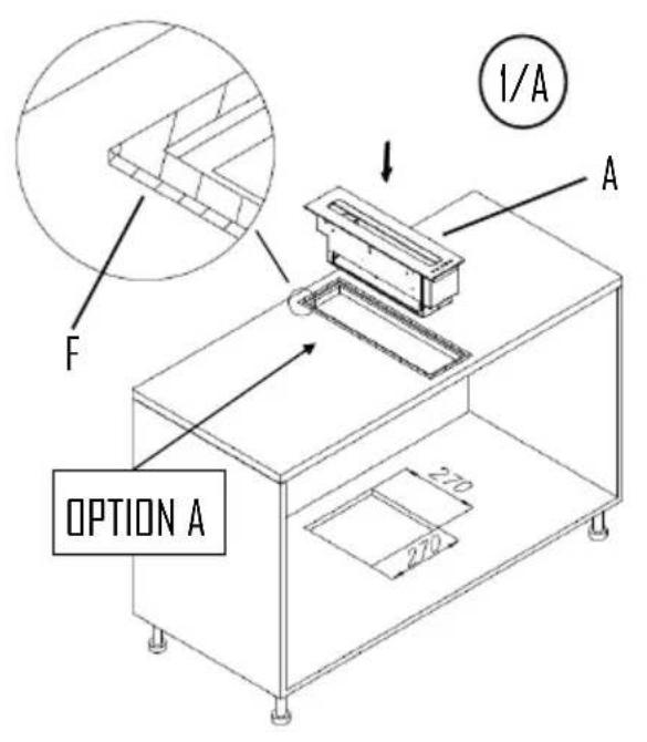
Top mounting of the built-in units
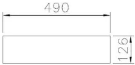
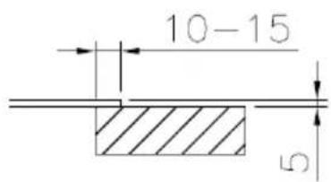
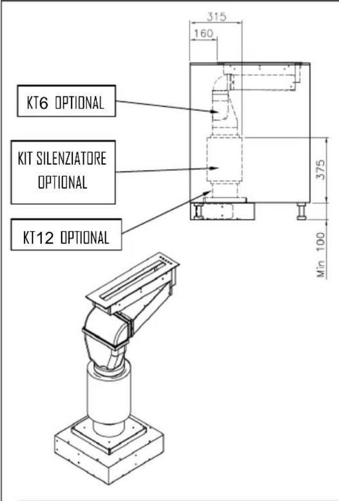
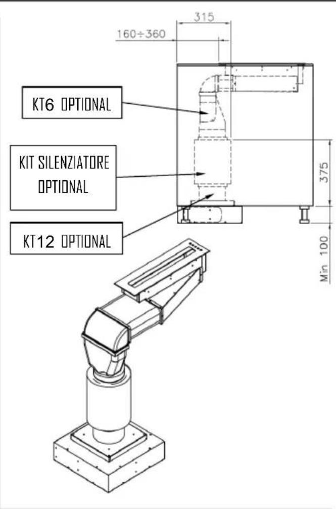
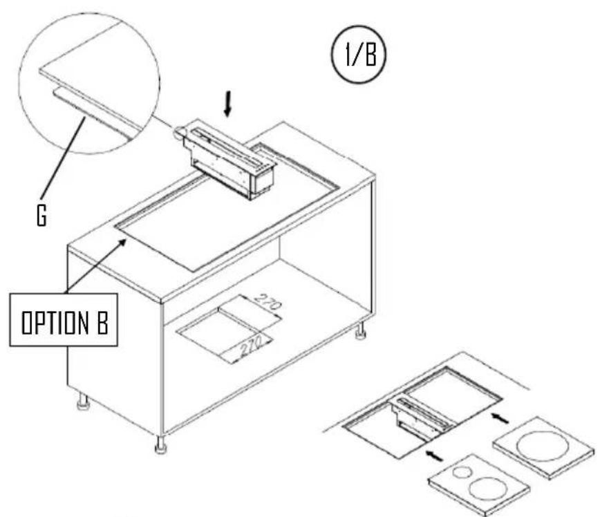
Flush mounting of the built-in units:
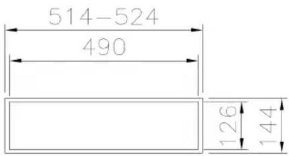
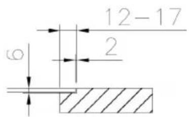
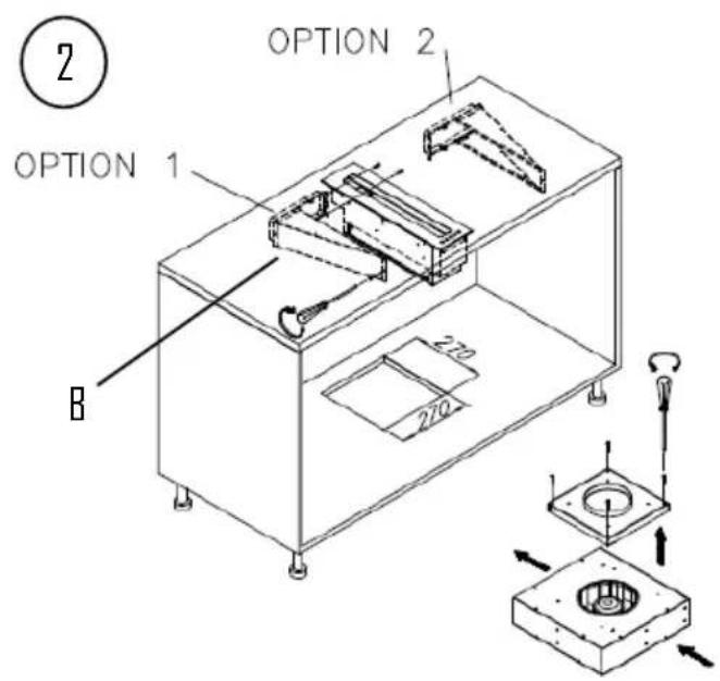
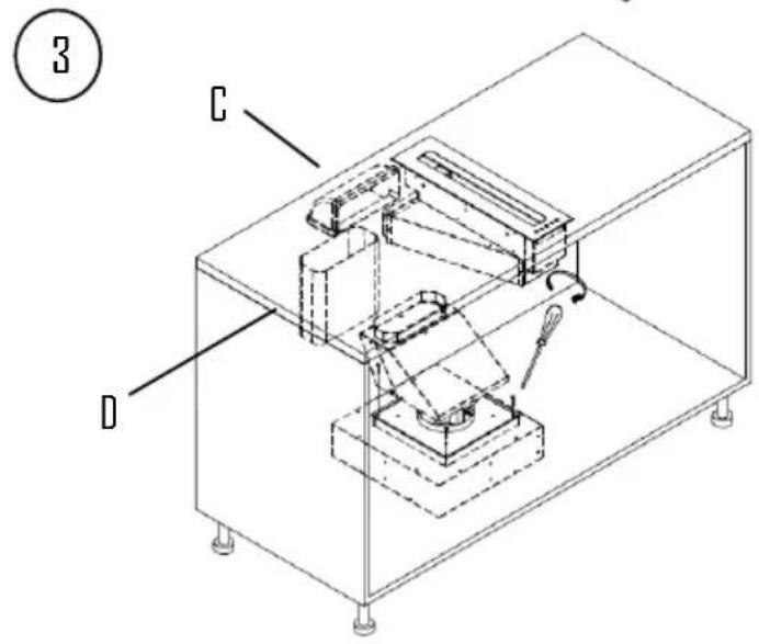
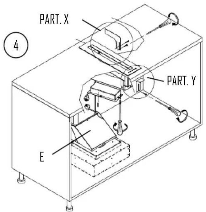
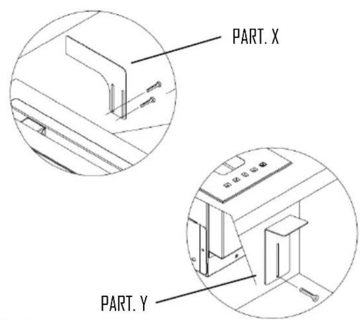
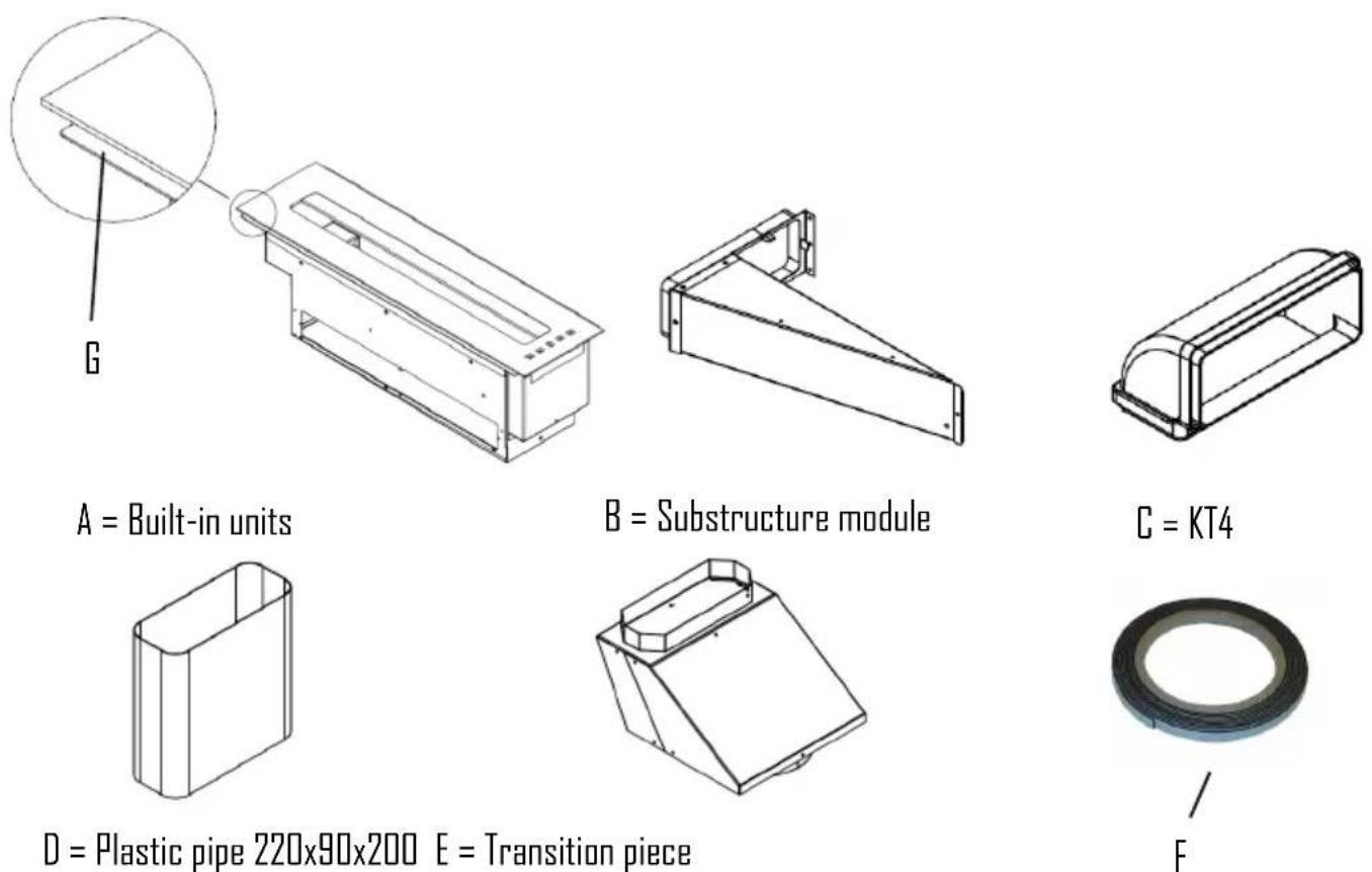
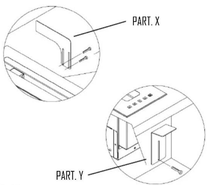
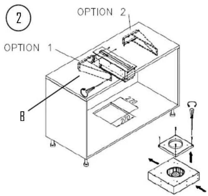
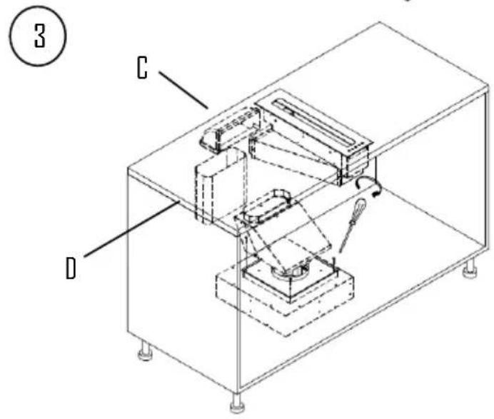
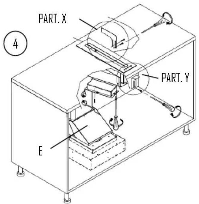
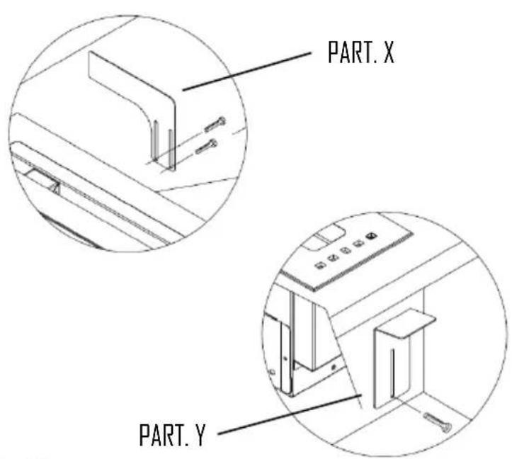
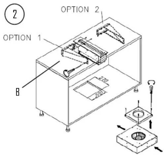
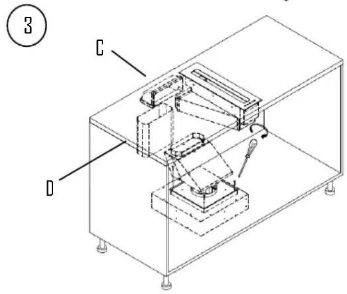
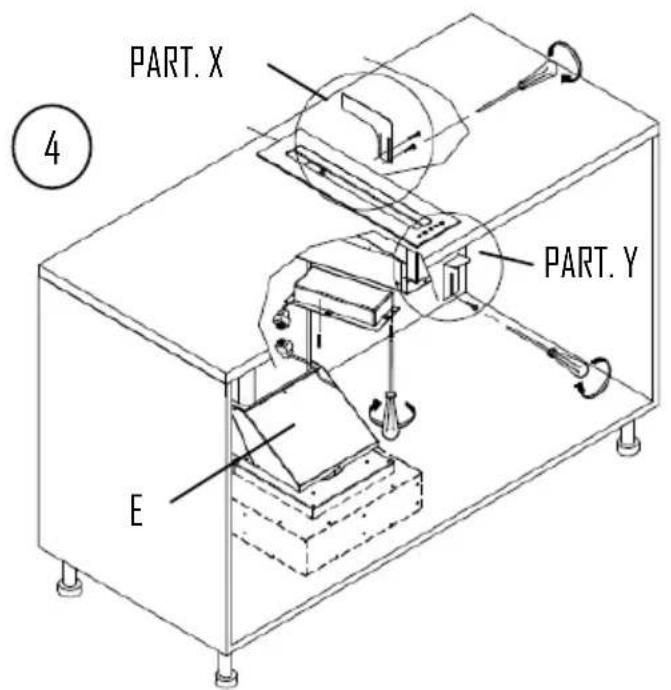
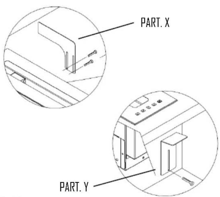
To assemble the hood use the accessories that are supplied and follow the instructions.
EN - 11
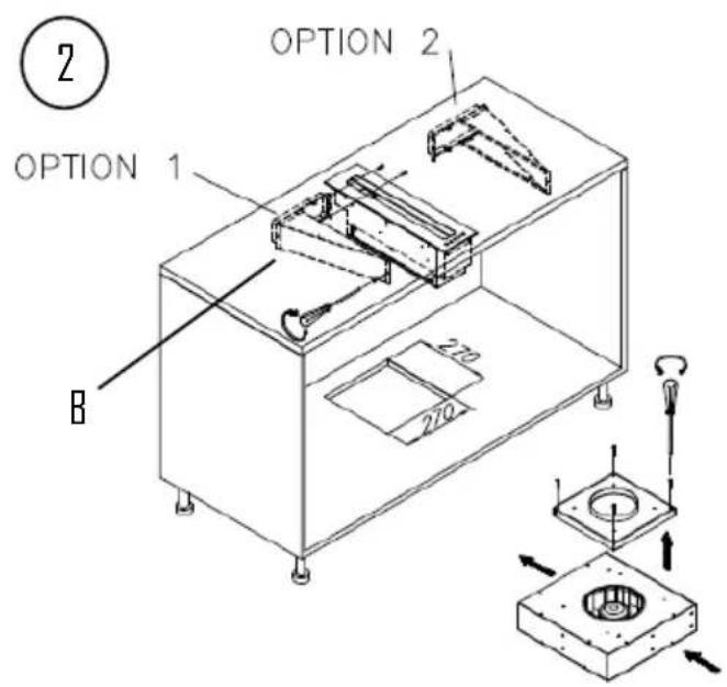
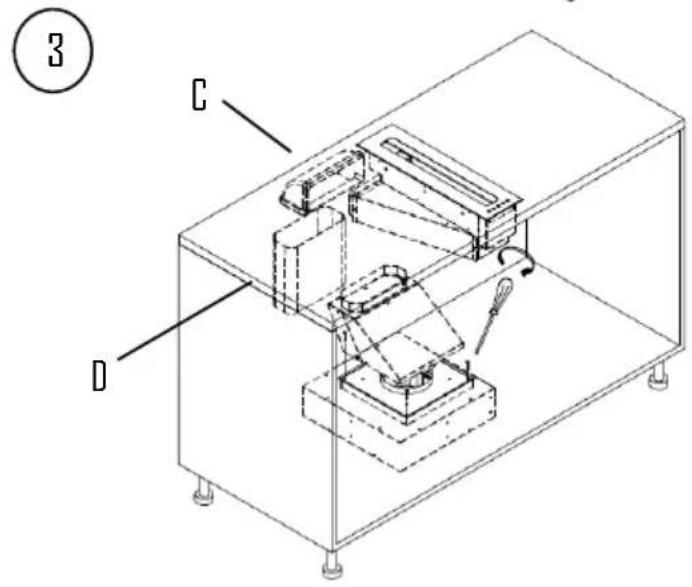
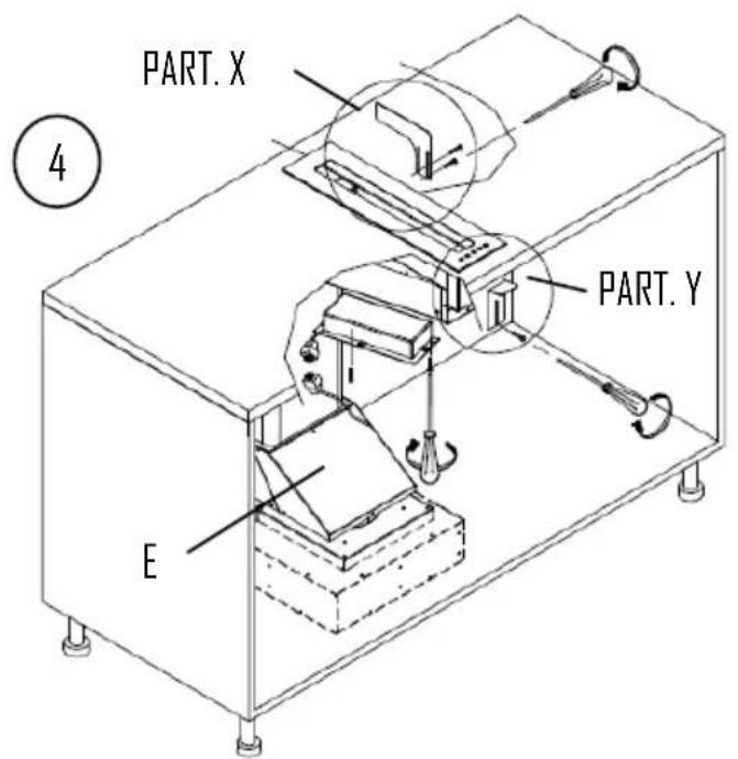
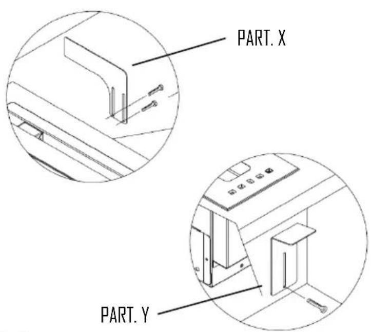
EN - 12
ELECTRIC WIRING
The electric wiring must be performed by a specialised electrician fully respecting current standards and legislation in force.
Check that the power supply corresponds to the voltage requested by the hood, which is given on the silver label stuck inside the hood.
Ensure that the wiring system conforms to current standards and the earth discharge works efficiently.
Pay special attention to the hood power cable, ensure that it does not pass through any holes without a cable clamp.
For direct connection to the electrical mains is necessary to provide a device that ensures disconnection from the electrical mains, with an opening distance of the contacts that allows the complete disconnection under the conditions of overvoltage category III, in accordance with the rules of installation.
The plug or omnipolar switch must be accessible when the unit is installed
If the power cord is damaged, it must be replaced by a special cord or assembly available from the manufacturer or its service agent. The cable used must be of type H05VV-F 3 x 0.75 mm2 minimum cross-section.
The manufacturer declines all responsibility if the current accident prevention standards in force are not respected, which are needed for the wiring system to operate correctly
CONTROL
DIGITAL CONTROLS
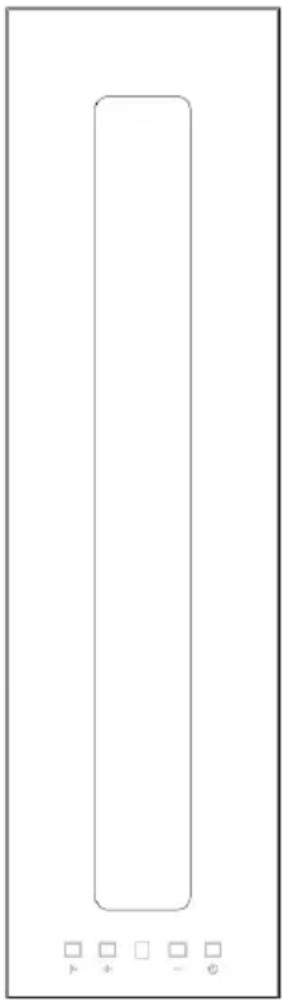
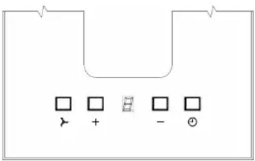
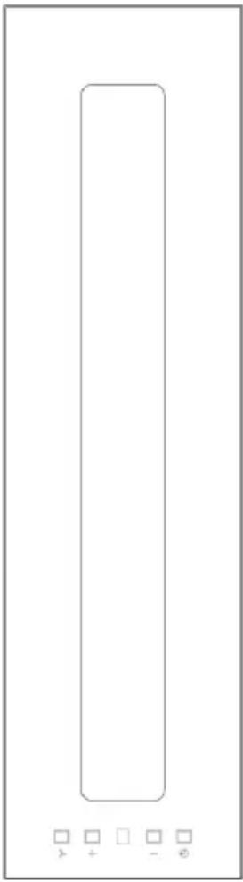
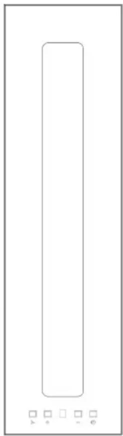
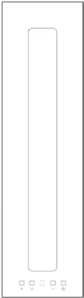
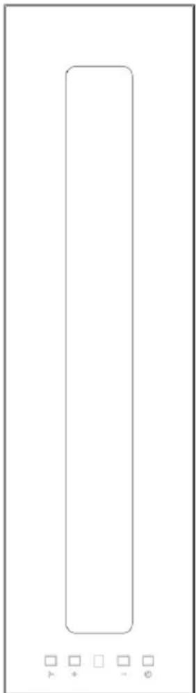
In this version there are four soft touch buttons and a display
One button for turning on at 2nd speed and for turning the motor off.
Two buttons + and - for increasing and decreasing the motor speed.
A TIMER button for turning the motor off after 10 minutes.
When the timer is activated, the number on the display flashes.
Special functions:
After 100 hours use, a D or a letter A will start flashing on the DISPLAY to remind the user to clean the metal filters.
After washing the metal filters, reset the hour meter by pressing the TIMER button for more than three seconds with the hood turned off.
When the hour meter has been reset a dash
appears on the display, with the hood turned off.
natural_image
Pure electrical circuit lines without any symbolsUSE AND MAINTENANCE
Before beginning any sort of cleaning or maintenance work, turn power off to the hood by turning the main switch to 0 (OFF).
Cleaning the metal filters:
natural_image
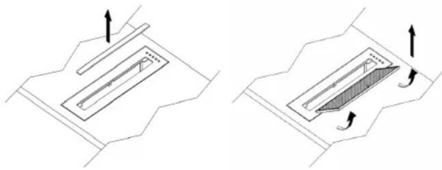
Two technical diagrams showing mechanical components with directional arrows, no text or symbols presentThe metal filters fitted in the hood should be washed every month, depending on how much the hood is used, using hot water and a liquid detergent that is not too aggressive. The metal filters can be removed by the special handle. After washing the filters, they must be thoroughly dried and reassembled correctly.
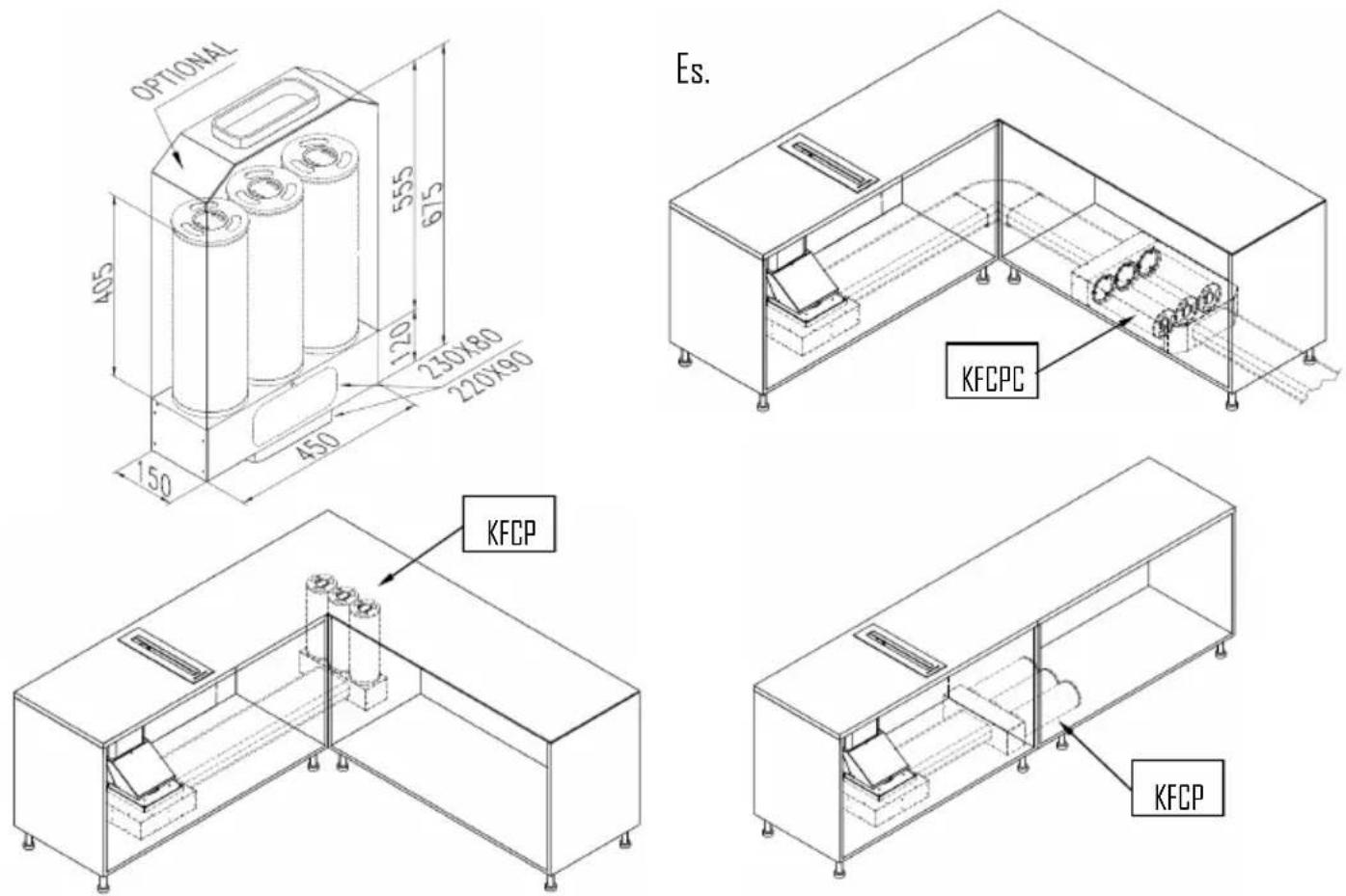
Carbon filters OPTIONAL (KFCP e KFCPC)
If the hood is used with an internal recycle filtering system must be used carbon filters (KFCP and KFCPC). The active carbon in the filters traps the cooking smells.
Cleaning the hood
Regular cleaning of the surface areas saves the hassle of removing tougher stains later.
For the painted or copper plated hoods just use a soft cloth with warm water and a neutral detergent. Do not pour the detergent directly onto the hood or use powdery or abrasive products
Do not use aggressive products, chemical solvents or derivatives of oil distillates that could leave oily traces which could cause oxidation and polymerisation.
The manufacturer accepts no responsibility for damage to the surface of the hood due to failure to respect these instructions.
BEDIENUNGS-, WARTUNGS- UND INSTALLATIONSHANDBUCH ABZUGSHAUBE
natural_image
Technical line drawing of a mechanical assembly with a magnified inset showing a component labeled 'G' (no text or symbols beyond label)A = Kochfeldabzug
natural_image
Simple line drawing of a rectangular box or container (no text or symbols)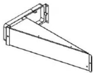
natural_image
Technical line drawing of a metal bracket with mounting flanges (no text or symbols)B = Unterbau-Modul
natural_image
Isometric line drawing of a 3D mechanical part with a sloped top and rectangular base (no text or symbols)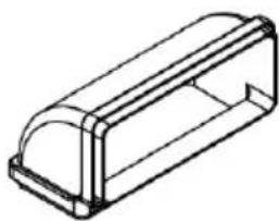
natural_image
Isometric line drawing of a rectangular electronic component with a dome-shaped top (no text or symbols)C = KT4
natural_image
Circular black tape or film reel with a single black mark, no visible text or symbolsF
DE - 20
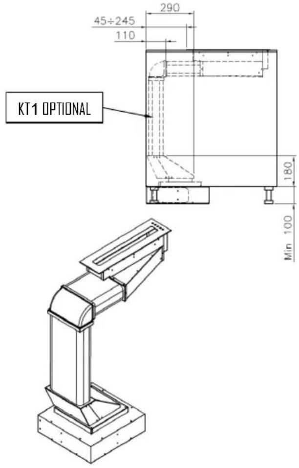
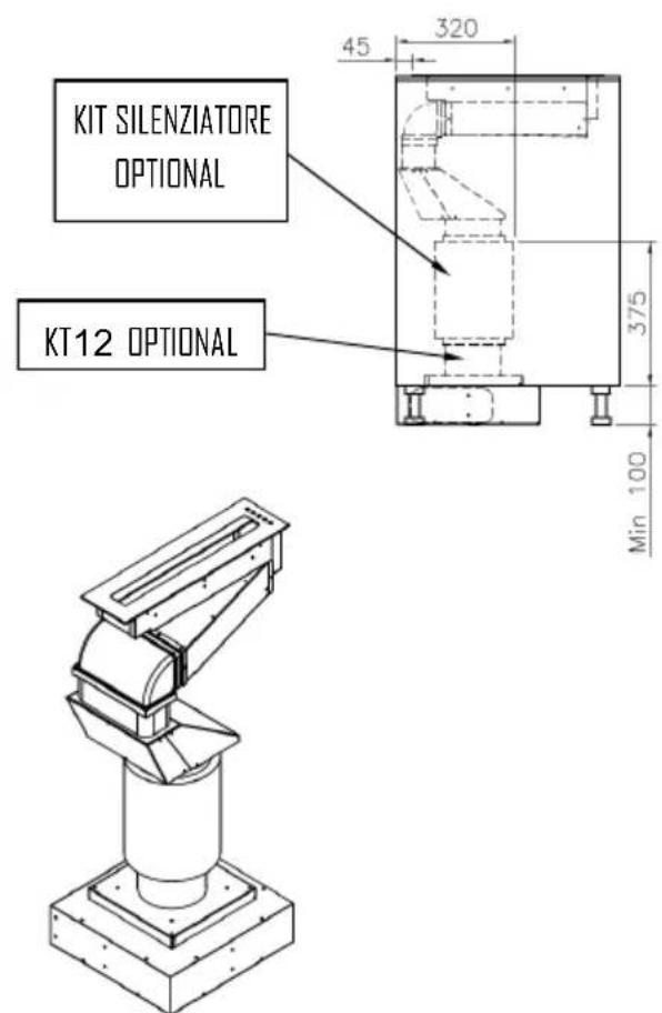
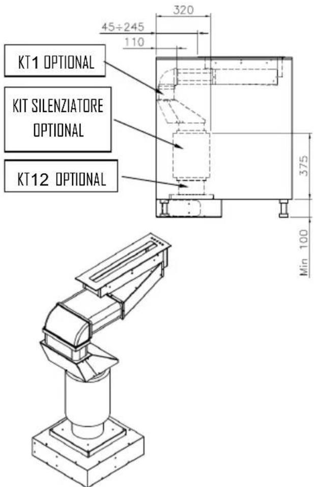
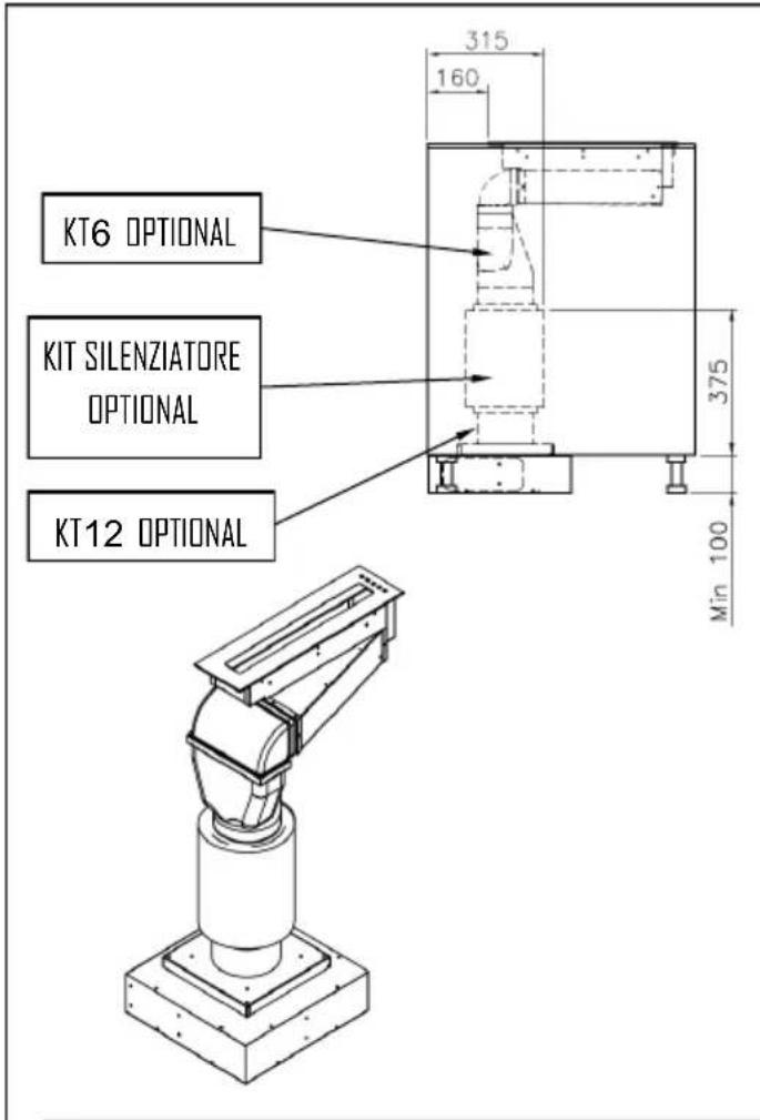
STROMANSCHLUSS
natural_image
Pure electrical circuit lines without any symbolsnatural_image
Two technical diagrams showing mechanical components with directional arrows, no text or symbols presentnatural_image
Technical line drawing of a mechanical device with a rectangular frame and curved internal components (no text or symbols)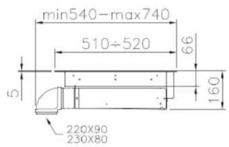
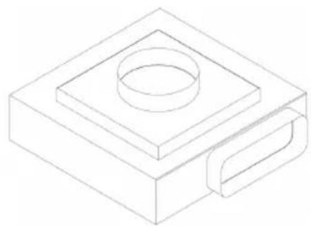
natural_image
Isometric line drawing of a mechanical component with a square base and circular top (no text or symbols)
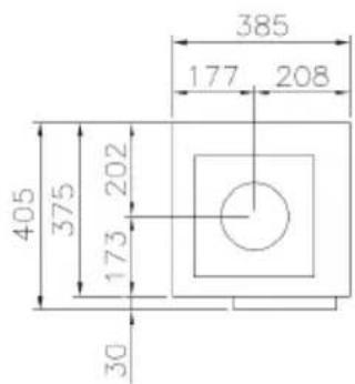
FR - 26
natural_image
Technical line drawing of a mechanical component with a magnified inset showing a section labeled 'G' (no text or symbols beyond label)A = Dispositif aspirant
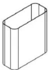
natural_image
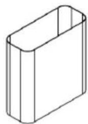
Simple line drawing of a rectangular box or container (no text or symbols)D = Tuyau en plastique 220x90x200 E = Raccord
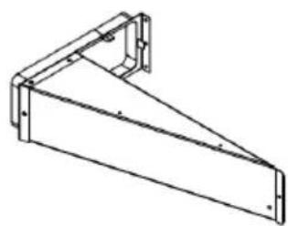
natural_image
Technical line drawing of a metal bracket or support structure (no text or symbols)B = Module support
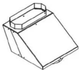
natural_image
Isometric line drawing of a 3D mechanical part with a sloped top and rectangular base (no text or symbols)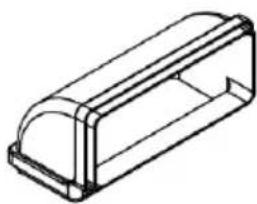
natural_image
Isometric line drawing of a rectangular electronic component with a curved top and internal structure (no text or symbols)C = KT4
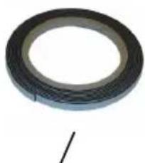
natural_image
Circular black rubber tape with a single seam, no text or symbols visibleF
FR - 28
RACCORDEMENT ELECTRIQUE
natural_image
Pure diagram of a U-shaped structure with control symbols (no text or labels)
natural_image
Pure electrical circuit lines without any symbolsUTILISATION ET ENTRETIEN
natural_image
Two technical diagrams showing a mechanical component with directional arrows indicating motion or force (no text or symbols present)natural_image
Technical line drawing of a mechanical component with a magnified inset showing a section labeled 'G' (no text or symbols beyond label)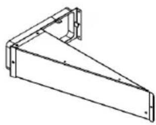
natural_image
Technical line drawing of a metal bracket or support frame (no text or symbols)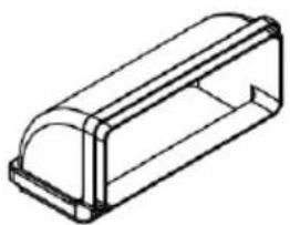
natural_image
Isometric line drawing of a rectangular electronic component with a dome-shaped top (no text or symbols)A = Kookveldafzuiging B = Onderbouwmodule
natural_image
Simple line drawing of a rectangular box or container (no text or symbols)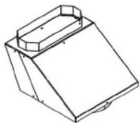
natural_image
Isometric line drawing of a 3D mechanical part with a sloped top and rectangular base (no text or symbols)C = KT4
natural_image
Circular black rubber tape with a single hole, isolated on white background (no text or symbols)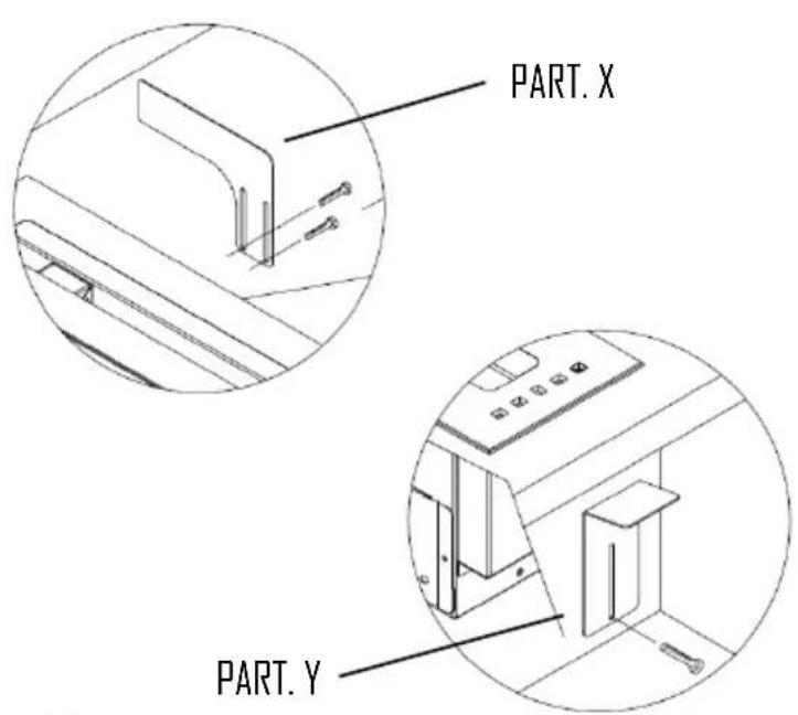
NL - 36
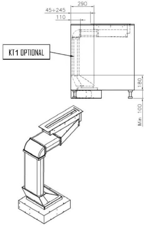
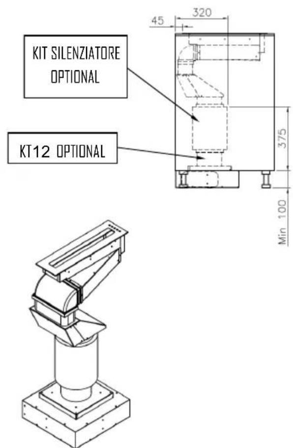
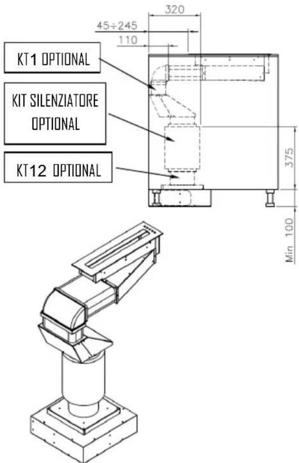
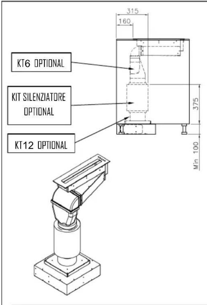
natural_image
Pure electrical circuit lines without any symbolsGEBRUIK EN ONDERHOUD
natural_image
Two technical diagrams showing mechanical components with directional arrows, no text or symbols presentnatural_image
Technical line drawings of two mechanical components, one with a curved housing and the other a square base with a circular cutout (no text or symbols)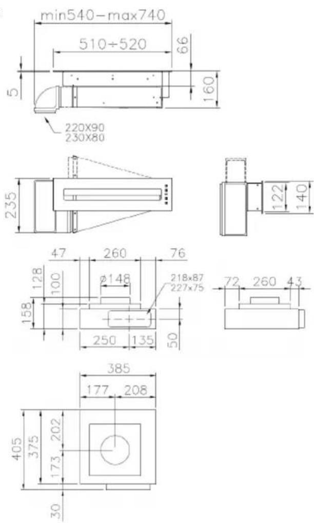
natural_image
Technical line drawings of mechanical components, including a G-shaped component and three views (no text or symbols)A = La campana de encimera B = Módulo empotrable
natural_image
Simple line drawing of a rectangular box or container (no text or symbols)D = Tubos de plástico 220x90x200
natural_image
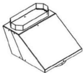
Technical line drawing of a 3D mechanical part with a sloped top and rectangular base (no text or symbols)E = Pieza de paso
ES - 43
natural_image
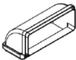
Isometric line drawing of a rectangular electronic component with a dome-shaped top (no text or symbols)C = KT4
natural_image
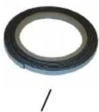
Circular black rubber tape with a single seam, no text or symbols visibleF
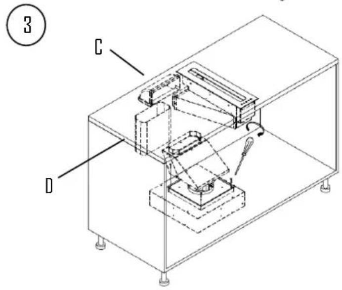
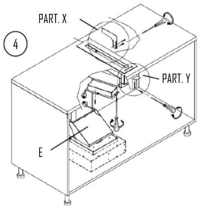
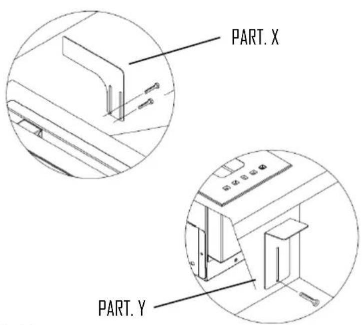
ES - 44
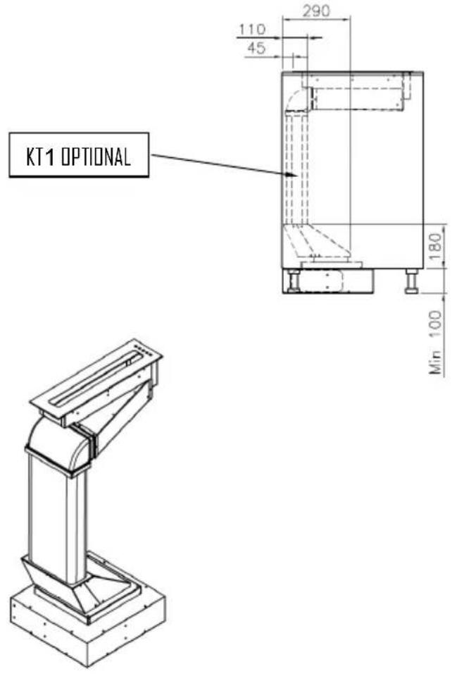
natural_image
Pure diagram of a U-shaped structure with control symbols (no text or labels)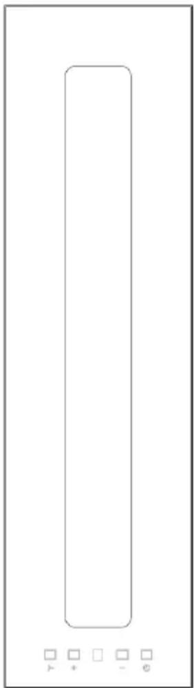
natural_image
Pure electrical circuit lines without any symbolsUSO Y MANTENIMIENTO
natural_image
Two technical diagrams showing mechanical components with directional arrows, no text or symbols presentnatural_image
Technical line drawings of a mechanical component with three views: top view, front view, and side view (no text or symbols)natural_image
Simple line drawing of a rectangular box or container (no text or symbols)D = Tubos de plástico 220x90x200
natural_image
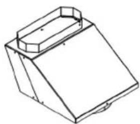
Isometric line drawing of a 3D mechanical part with a sloped top and rectangular base (no text or symbols)E = Přechod kus
CZ-51
natural_image
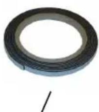
Circular black tape or film reel with a single mark, no visible text or symbolsF
CZ-52
ELEKTRICKÉ PŘIPOJENÍ
natural_image
Pure electrical circuit lines without any symbolsPOUŽITÍ A ÚDRŽBA
natural_image
Two technical diagrams showing mechanical components with directional arrows, no text or symbols presentwww.fulgor-milano.com

- EN This product complies with EU Directive 2002/96/EC.
- ALLACCIAMENTO ELETTRICO
- USO E MANUTENZIONE
- INSTRUCTIONS FOR USING, MAINTAINING AND INSTALLING THE HOOD
- WARNINGS
- INSTALLATION
- ASSEMBLY INSTRUCTIONS
- ELECTRIC WIRING
- CONTROL
- DIGITAL CONTROLS
- USE AND MAINTENANCE
- Cleaning the metal filters:
- Carbon filters OPTIONAL (KFCP e KFCPC)
- Cleaning the hood
- BEDIENUNGS-, WARTUNGS- UND INSTALLATIONSHANDBUCH ABZUGSHAUBE
- STROMANSCHLUSS
- RACCORDEMENT ELECTRIQUE
- UTILISATION ET ENTRETIEN
- GEBRUIK EN ONDERHOUD
- USO Y MANTENIMIENTO
- ELEKTRICKÉ PŘIPOJENÍ
- POUŽITÍ A ÚDRŽBA
Brand : Fulgor Milano
Model : FPH 5114 TC BK
Category : Range hood