Domusfire HR C39 - Boiler Cola - Free user manual and instructions
Find the device manual for free Domusfire HR C39 Cola in PDF.
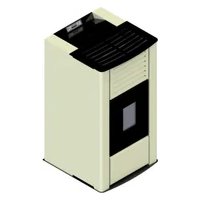
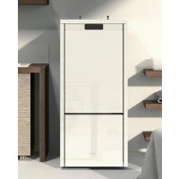
| Product Type | Automatic pellet boiler |
| Brand | Cola |
| Model | Domusfire HR C39 |
| Rated Power | 39 kW (estimated from model) |
| Power Supply | 230 V, 50 Hz |
| Fuse | 2 A |
| Fuel | Wood pellets conforming to DIN plus 51731, UNI CEN/TS 14961, Ö-Norm M 7135 |
| Hopper Capacity | Not specified (optional extra reserve of 250 kg) |
| Noise Level | 35 to 38 dB |
| Hydraulic Circuit Pressure | 1.1 to 1.5 bar |
| Safety Temperature | >85°C (thermostat) |
| Standards | CE, EN 303-5, EN 60335-1, EN 60335-2-102, EN 62233, etc. |
| Safety Systems | Safety thermostat, vacuum switch, safety valve (3 bar), overvoltage protection, backdraft protection |
| Cleaning | Daily: burner pot, ash pan; every 2-3 days: shake turbulators |
| Maintenance | Annual by authorized service center |
| Functions | Automatic ignition, weekly programming, flame modulation, DHW management |
| Included Accessories | Power cable, manual, opening key |
| Warranty | Subject to conditions, normal wear excluded |
Frequently Asked Questions - Domusfire HR C39 Cola
User questions about Domusfire HR C39 Cola
0 question about this device. Answer the ones you know or ask your own.
Ask a new question about this device
Download the instructions for your Boiler in PDF format for free! Find your manual Domusfire HR C39 - Cola and take your electronic device back in hand. On this page are published all the documents necessary for the use of your device. Domusfire HR C39 by Cola.
USER MANUAL Domusfire HR C39 Cola
484270011-M5_09/14 Hardware - M
Read the instructions carefully before installation, use and maintenance. The manual is an integral part of the unit.
COLA guarantees its products, except for parts subject to normal wear, in accordance with the current regulations. For the warranty terms, please contact the importer or the authorised agent who can integrate the compulsory warranty period with an additional period under his sole and exclusive responsibility.
The product warranty is invalidated for any trouble, breakage or accident due to failure to comply with or apply the instructions provided in this manual.
FR 71-103
Type of equipment and use
Name and address of the manufacturer
Heating boilers with automatic feeding wood pellet.
+390456144043/+390456144048
Info@anselmocola.com
The following harmonised standards or technical specifications (designations) which comply with good engineering practice in safety matters in force within the EEC have been applied :
Standards or other normative documents
As the manufacturer's authorised representative established within CEE, we declare under out sole responsibility that the equipment follows the provisions of the Directives stated above and that the technical file is made and kept at the Company COLA.
Nome e firma pericontodel fabbricante-Signed for and on behalf of the manufacturer
Type of equipment and use
Name and address of the manufacturer
Heating boilers with automatic feeding wood pellet.
Chauffage chaudiere a alimentation automatique de granules de bois.
Heizkessel mit automatischer Zuführung von Holzpellets.
Caldera de pellets de madera con alimentacion automatica.
+390456144043/+390456144048
Info@anselmocola.com
The following harmonised standards or technical specifications (designations) which comply with good engineering practice in safety matters in force within the EEC have been applied :
Standards or other normative documents
As the manufacturer's authorised representative established within CEE, we declare under out sole responsibility that the equipment follows the provisions of the Directives stated above and that the technical file is made and kept at the Company COLA.
En tant que fabricant et / ou son mandataires établi dans la Communauté, déclare sous sa propre responsabilité que l'équipment est conforme aux exigences essentielles fixées par les Directives énoncées ci-dessus et que le dossier technique est constitué et maintainu à la Société COLA. Als Hersteller und / oder genheigmer Vertreter in der EWG, man erklart unter der eigener Verantwortung, dass das Gerät die grundlegenden Anforderungen der Richtlinien oben angegeben entspricht und dass die technischen Unterlagen bei der Firma COLA verfasst und gehalten sind. Como el fabricante y/o representante autorizzato establecido en la CEE, declara bajo su propria responsabilidad que el equipo compte con los requisitos esenciales establecidos en las Directivas Mentionadas y que el expediente的技术ico se hace y se mantiene a la Compañía COLA.
Nome e firma pericontodel fabbricante - Signed for and on behalf of the manufacturer
Type of equipment and use
Name and address of the manufacturer
Heating boilers with automatic feeding wood pellet.
+390456144043/+390456144048
Info@anselmocola.com
The following harmonised standards or technical specifications (designations) which comply with good engineering practice in safety matters in force within the EEC have been applied :
Standards or other normative documents
As the manufacturer's authorised representative established within CEE, we declare under out sole responsibility that the equipment follows the provisions of the Directives stated above and that the technical file is made and kept at the Company COLA.
En tant que fabricant et / ou son mandataires établi dans la Communauté, déclare sous sa propre responsabilité que l'équipment est conforme aux exigences essentielles fixées par les Directives énoncées ci-dessus et que le dossier technique est constitué et maintainu à la Société COLA. Als Hersteller und / oder genheimgter Vertreter in der EWG, man erklart unter der eigener Verantwortung, dass das Gerät die grundlegenden Anforderungen der Richtlinien oben angegeben entspricht und dass die technischen Unterlagen bei der Firma COLA verfasst und gehalten sind. Como el fabricante y/o representante autorizo establishe en la CEE, declara bajo su propria responsabilidad que el equipo cumple con los requisitos esenciales establecidos en las Directivas mentionadas y que el expediente的技术ico se hace y se mantiene a la Compania COLA.
Nome e firma pericont del fabbricante - Signed for and on behalf of the manufacturer
CE MARKING INFORMATION
INFORMATIONS RELATIVES AU MARQUAGE CE
m = 311
Test Centre for Energy Appliances - NB 2456
EN 303-5:2012Report nK8552012T1-T2-S3+K9702013Z1
| TipologiaType of equipment / Type d'appareil / Geräte typ / Tipo de dispositivo | Caldaia a pelletHeating Boiler / Chaudière à granulés / Kessel / Caldera | ||||
| Marchio commercialeTrademark / Marque de commerce / Marke / Marca | COLA | ||||
| ModelloModel / Modèle / Model / Modelo | DOMUSFIREC29 HR | DOMUSFIREC35 HR | |||
| CombustibleFuel / Carburant / Brennstoff / Combustible | Pellet di Legno / Wood pellet / Granules de bois / Holzpellet / Pellets de maderaUNI EN14961-2_classe A1 | ||||
| Potenza termica introdotta*Heat input/ Puis.introduite/Eingefuhr Leistung / Pot.introducida | kW | 29,0 - 6,4 | 34,4 - 6,4 | ||
| Potenza termica nominale*Nominal heat output / Puis. nominale/Nenleistung / Pot. Nominal | kW | 27,4 - 5,78 | 32,4 - 5,78 | ||
| Rendimento termico*Efficiency / Rendernent / Wirkungsgrad / Rendimento | % | 94,45 - 90,14 | 94,18 - 90,14 | ||
| Consumo orario*Fuel consumption / Consummation horarie / Stundi Verbrauch / Consumo horario | kg/h | 6 - 1,32 | 7,1 - 1,32 | ||
| Emissione CO al 10%O2*Emission CO / Emission CO / CO Emission / Emissiones de CO | %mg/m3 | 0,005 - 0,04061,0 - 497,7 | 0,007 - 0,04083,0 - 497,7 | ||
| Emissione CnHm al 10% O2*Emission CnHm / Emissions CnHm / CnHm Emission / Emission CnHm | mg/m3 | 6,7 - 18,8 | 6,6 - 18,8 | ||
| Emissione NOx al 10% O2*Emission NOx / Emissions NOx / NOx Emission / Emissiones de NOx | mg/m3 | 146,7 - 116,4 | 147,1 - 116,4 | ||
| Emissione polveri PP al 10% O2*Emission dust PP/Emis de poussières PP/Staubemission PP/Emis de polvo PP | mg/m3 | 24,1 - 9,5 | 23,6 - 9,5 | ||
| Emissione CO al 13%O2*Emission CO / Emission CO / CO Emission / Emissiones de CO | %mg/m3 | 0,004 - 0,02944,4 - 362 | 0,005 - 0,02960,4 - 362 | ||
| Emissione CnHm al 13% O2*Emission CnHm / Emissions CnHm / CnHm Emission / Emission CnHm | mg/m3 | 4,9 - 13,78 | 4,8 - 13,78 | ||
| Emissione NOx al 13% O2*Emission NOx / Emissions NOx / NOx Emission / Emissiones de NOx | mg/m3 | 106,8 - 84,6 | 107 - 84,6 | ||
| Emissione polveri PP al 13% O2*Emission dust PP/Emis de poussières PP/Staubemission PP/Emis de polvo PP | mg/m3 | 17,6 - 6,9 | 17,2 - 6,9 | ||
| Emissione particolato totale PPBT al 13% O2*/ Total dust emissionTotale émis particules / Insgesamt Staubemission / Total émis particulas | mg/m3 | 19,66 - 12,69 | 19,22 - 12,69 | ||
| Temperatura max acqua impostabileSet max temp./Temp. max de l'eau reglable/Max wassertemp.set/Temp.max agua establecer | °C | 80 | |||
| Pressione max acqua di esercizio / Max working pressurePressione max eau d'utilisation / Max Betriebsdruck / Presion max funzionamento | bar | 3 | |||
| Capacità acqua termocamera / Heating chambre capacityCap.chambre comb./ Fassungsvermogen Warnekommer/Cap.camara těrmica | I | 30 | |||
| Attacchi idraulici riscaldamento / Hydraulic connectionsRaccordements hydrauliques/ Hydraulikanschlässe / Conexiones hidrálicas | * | 1 | |||
| Capacità serbatoio pellet / Pellet stove capacityCapacità du reservoir è granulés / Behalterinhalt / Capacità del deposito | kg | 68 | |||
| Classe della caldaia rif. EN303-5_2012Boiler class / Chaudière class/Klasse von Kessel / Classe de caldera | 5 | ||||
| Perdite di carico lato acqua ΔT 10K / Water resistancePerte de charge sur le coté/Druckabfall auf der Wasserseite/Peridía dearga en lado del agua | mbar | 386,9 | 521,7 | ||
| Perdite di carico lato acqua ΔT 20K / Water resistancePerte de charge sur le coté/Druckabfall auf der Wasserseite/Peridía dearga en lado del agua | mbar | 96,73 | 130,4 | ||
| Temperatura uscita fumi*/ Fume outlet temperatureTemperature de fume/ Abgastematur / Temperatura salute humos | °C | 134,3 - 62,6 | 148,6 - 62,6 | ||
| Portata dei fumi*Flue gas flow / Debit gaz de combustion / Abgasmassenstrom / Caudal de humos | g/s | 14,1 - 5,4 | 16,3 - 5,4 | ||
| Traggio canna fumaria min-maxDraught min -max / Tirage fumee min-max / Minderstug min-max / Tiro min - max | Pa(mbar) | 10 - 14 (0,10 - 0,14) | |||
| Diametro tubo scarico fumi | mm | 100 | |||
| Fume outlet pipe / Tuyau d'évacuation fumées / Rauchabzugrohr / Tubo salute humos | |||||
| Alimentazione elettricaElectrical power / Alimentazione elettrice / Elektrische Versorgung / Alimentación electrónica | 230V - 50Hz - 2A | ||||
| Assorbimento elettricoRated input power / Consummation elettrice / Stromaufnahme / Consumo elettrico | W | Accensione/Start 440 - Stand by 4 - P nom 120 - P.rid. 110 | |||
| Dimensioni d'ingombro H x L x PDimensions / Dimensions / Abmessungen / Medidas | mm | 1300x700x698 | 1300x700x698 | ||
| Peso a vuotoWeight / Poats / Behalterinhalt / Peso | kg | 272 | 275 | ||
- A potenza nominale e ridotta / Nominal output and Reduced output / A' Puisstance nominale et de faible puissance / Nennwert - Reduzierter wert / a Potencia nominal e reducida.
Il consumo di combustibile può variarere dal tipo di pellet utilizzato / Fuel consumption can vary according to the type of wood pellet used.
** La consommation peut varier selon le type de Poèle à granulés utilise / Der Kraftstoffverbrauch kann durch die Art des verwendeten Pelletoten varieren.
El consumo de combustible pueda variar según el tipo de pellet de madera realizada.
COLA
1 AVVERTENZE GENERALI. 10
1.1 Introduction 41
1.2 Using the manual. 41
1.3 Safety rules.. 41
1.4 Technical description 42
1.5 Permissible use and fuel. 43
1.6 Accessories supplied 43
1.7 Reference standards.. 44
1.8 Data plate. 44
1.9 Boiler decommissioning 44
1.10 Instructions for requesting assistance and replacement parts 44
2 TRANSPORT AND INSTALLATION ....45
2.1 Conditions of supply, transport and storage 45
2.2 Place of installation, positioning and fire-prevention safety 46
2.3 Air inlet.. 48
2.4 Fume exhaust 48
2.4.1 Types of installations.. 48
2.5 Turbulator and brazier position check 49
2.6 Electrical connection 49
2.7 Wiring diagram.. 50
2.8 Wiring diagram for zone system.....50
2.9 Plumbing connections.. 50
2.9.1 System water filling.. 51
2.9.2 System water characteristics....51
2.9.3 DHW system 51
2.9.4 Boiler hydraulic diagrams .52
2.10 Emergency 53
3 BOILER SAFETY. 54
3.1 Safety distance from flammable materials 54
3.2 Fume exhaust safety.. 54
3.3 Combustion chamber overpressure safety 54
3.4 Overheating - safety thermostats.....54
3.5 Safety against flare-back in the pellet chute 54
3.6 Overcurrent protection device....54
3.7 Water circuit overpressure safety.....54
3.8 Fume extractor fan failure 54
4 BOILER USE. 55
4.1 Introduction 55
4.2 Description of control panel............55
4.3 Lighting 56
4.3.1 Check before lighting..56
4.3.2 Startup stage 56
4.4 Work stage 57
4.4.1 Modifying the water temperature setting. 57
4.4.2 Cleaning the brazier 58
4.4.3 DHW with rapid heat exchanger 58
4.4.4 DHW with storage tank............58
4.4.5 System with puffer / heat accumulator 58
4.5 Shutting down 58
4.6 Menu 59
4.6.1 Menu 01 - Chrono setting ....... 60
4.6.2 Menu 02 - User adjustments .... 61
4.6.3 Menu 03 - User setting.. 61
4.6.4 Menu 04 - boiler status.. 62
4.6.5 Menu 05 - Technician settings... 62
4.7 Thermostat - external chronothermostat 62
4.8 Idle period (end of season) 62
5 BOILER CLEANING 63
5.1 Cleaning the brazier - brazier holder 63
5.2 Cleaning the ash container 63
5.3 Cleaning the fume extractor and combustion chamber 63
5.4 Cleaning the air flow meter 64
5.5 Cleaning the flue - flue connection... 64
5.6 Cleaning the exchanger with turbulator-shaker device 64
6 MAINTENANCE 65
6.1 Introduction 65
6.2 Removing the boiler cladding.. 65
6.3 Boiler internal parts 65
6.4 Electrical components 67
6.5 Standard hydraulic components.. 67
7 TROUBLESHOOTING 68
7.1 Alarm management 68
8 INSTALLER 70
8.1 Menu installer settings 70
1 GENERAL INFORMATION
1.1 Introduction
Dear Customer,
First of all we wish to thank you for the trust placed in us by purchasing one of our products. Please read and carefully follow the advice given in this installation, use and maintenance manual in order make best use of the product.
1.2 Using the manual
The Manufacturer reserves the right to make technical or aesthetic changes to the products at any time without notice.
Boiler installation, use and maintenance operations must comply with the requirements given in this manual as well as the European, National, Regional, Provincial and Municipal laws and regulations.
The drawings, measurements, diagrams and any other configurations are given only by way of example.
This manual is intended for the user of the heating/hot water system and is an integral part of the product; make sure it always stays with the unit, even if sold, transferred to another owner or installed in another place, so that it can be consulted at any time.
If lost or damaged, ask the authorised Service Centre for a copy so that the unit always has its own manual.
|  | This symbol indicates the presence of an important message; failure to pay attention to it can result in serious damage to the boiler and even injury. |
| Pay special attention to "words in bold face" |
1.3 Safety rules
- Read the use and maintenance manual before installing, lighting and servicing the boiler.
- Have installation, the electrical connection, testing and maintenance carried out by a qualified and/or authorised technician.
- Connect the boiler to an approved flue via an inspectionable terminal. The connection of more than one unit is possible only if allowed by the local regulations and by the flue control authority.
- Connect the boiler to the extraction system by means of a pipe or air inlet from outside.
- Connect the boiler to an approved 230V - 50Hz electrical socket.
- Make sure the electrical system and the sockets are suitable for the maximum absorption of the unit, specified on the label and in this manual.
- The power plug must be easily accessible.
-Connect the unit to the heating system; under no circumstances can it be used without the hydraulic connection and without water in the heating chamber and system.
-This unit must not be used by people (including children) with limited physical, sensory or mental abilities or without experience and knowledge of it, unless instructed in its use by those responsible for their safety. - Children must be supervised to make sure they do not play with the unit and in the place of installation.
- Arrange the power cable and any cables of external sensors so that they do not touch hot parts of the unit.
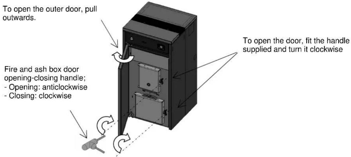
- Do not operate the unit with the fire door and/or ash box door open.
- Do not close or reduce the size of the combustion air inlet and fume exhaust openings.
- The boiler must not be used as an incinerator, but exclusively to heat the water of the heating and/or DHW system, only using wood pellets having the characteristics described in this manual as fuel.
- Do not use flammable liquids or substances to light the boiler.
- The boiler must not be used as a waste incinerator.
- Do not handle easily flammable or explosive substances near the boiler while it is in operation.
- Avoid direct contact with parts of the unit that may become very hot during operation.
- The boiler must be disconnected from the power supply and cold before carrying out any maintenance.
- Ensure an ambient temperature of between 0^ and 35^ in the place of installation, avoiding too high air humidity (e.g. in the presence of laundry hanging out to dry).
- Do not handle easily flammable or explosive substances near the boiler while it is in operation.
-Do not modify safety or adjustment devices without the manufacturer's express permission.
-Any tampering and/or unauthorized replacements with non-original parts of the boiler can create a risk for the user's safety and relieves the manufacturer of any civil or penal liability.
-Only use original replacement parts recommended by the manufacturer. - In case of malfunction, the boiler can be switched on again only after eliminating the cause of the problem; in any case, do not disable the safety systems.
- In case of fire, turn the heating system off, disconnect the power and use adequate systems to extinguish the flames, and/or call the Fire Department.
- Clean the brazier regularly at every lighting and/or pellet reloading.
-Avoid the formation of smoke and unburned products during lighting and/or normal operation; an excessive - amount of unburned pellets in the brazier must be removed manually before proceeding with lighting.
-Service the boiler at least once a year, planning it in advance with the personnel of the authorised Service Centre.
-In case of operation faults, the boiler can only be relit after eliminating the cause of the problem; otherwise, contact the After-Sales Service.

The manufacturer declines any liability for problems, breakage or accidents caused by failure to follow or apply the instructions contained in this manual.
1.4 Technical description
The boiler works exclusively on pellets and enables easy installation with the heating and DHW system. Its automatic control systems ensure optimum thermal efficiency and complete combustion; there are also systems to ensure safe operation for the internal components and the user. This unit must only be used for heating water to a temperature lower than boiling point.
When correctly installed, the unit works in any outside climatic conditions; in any case, in critical conditions (strong wind, frost, etc.) the safety systems can cut in and shut down the boiler.
The boiler comes complete with a fume extractor, pellet feed gearmotor, , high efficiency pump for the heating circuit and of all the control and safety components. During operation the unit generates very little noise, with levels between 35 and 38 dB.
For technical data, refer to the table on page 8.
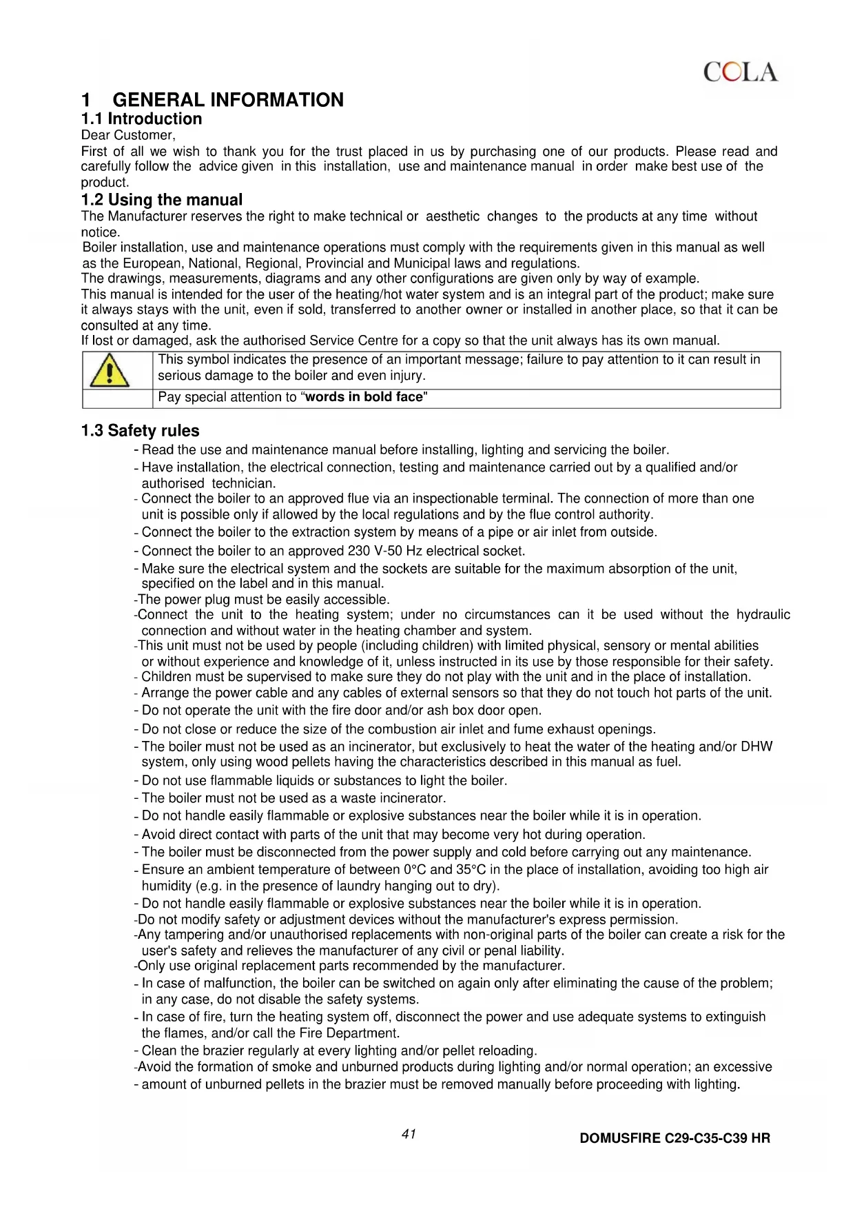
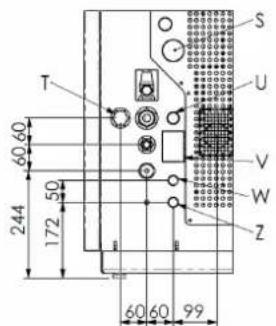
Overall dimensions Pellet boiler model DOMUSFIRE C29 HR - DOMUSFIRE C35 HR- DOMUSFIRE C39 HR
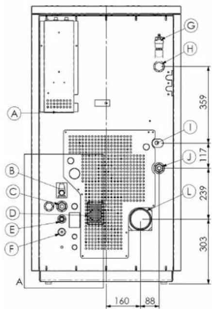
DETTAGLIO A
DETAIL A
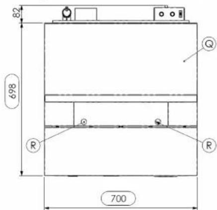
KEY:
Power cable connection
Overpressure water discharge (1/2" F - 3 bar)
Heating system return (1" M)
Water supply connection (1/2 F)
Combustion air inlet 60mm
F-System water drain
System air drain
-Connection-delivery without pump (1^ )
① Delivery pump inspection
Heating system delivery (1" M)
Fume exhaust pipe connection 100mm
Pressure/temperature gauge
Control panel model EVO
Door to access fire door and ash box
P)-Adjustable feet
- Pellet hopper door
(R)-Turbulator shaker knob
KEY - OPTIONAL ELEMENTS:
S - OPT DHW delivery pump inspection
T - OPT DHW return (3/4" pump)
U - OPT DHW delivery (3/4" M pump)
V - DHW overpressure water discharge
(1/2"F-6 bar)
W-OPT DHW return (1/2" M exchanger)
Z - OPT DHW delivery (1/2" M exchanger)
ACCESSIONS ON REQUEST:
- DHW ASSEMBLY WITH PUMP AND EXCHANGER INSIDE BOILER
- DHW ASSEMBLY WITH PUMP INSIDE BOILER
- SUPPLEMENTARY PELLET HOPPER - CAPACITY approx. 250kg
1.5 Permissible use and fuel
The pellet boilers work exclusively on pellets in various types of wood complying with Standard DIN plus 51731 or UNI EN 14961-2 or Ö-Norm M 7135 or having the following characteristics:
| Heat value | min 4.8 kWh/kg (4180 kcal/kg) |
| Density | 680-720 kg/m3 |
| Moisture | max 10% weight |
| Diameter: | 6 ±0.5 mm |
| Ash percentage | max 1.5% weight |
| Length: | min 6 mm- max 30 mm |
| Composition: | 100% untreated wood from the wood industry or post consumer without added binding substances or bark, complying with the current regulations |
| Packing in bags made from environmentally friendly or biodegradable material or paper | |
The pellet hopper is at the back of the boiler.
The door is located in the top part and loading occurs manually only with the boiler off, making sure not to overfill.
The use of pellets with characteristics different from those tested by the technician during first lighting involves a new setting of the boiler pellet loading parameters; this operation is not covered by the warranty.

-Store the pellets in a dry place.
-For reasons of regular and efficient operation, pellets or other fuels cannot be manually loaded in the brazier.
-Over time, the pellet hopper accumulates dust which could compromise proper feeding, therefore it is advisable to remove any dust before reloading pellets.
-Do not load non-conforming fuels in the hopper.
-Do not put foreign bodies such as containers, boxes, bags, metals, etc., in the hopper.
- The use of poor quality or non-conforming pellets will damage and compromise the unit's operation, invalidating the warranty and relieving the manufacturer of any liability.
1.6 Accessories supplied
The supply includes:
- Power cable;
- Installation, use and maintenance manual;
- Opening - closing key.
1.7 Reference standards
Standard UNI 10683:2012 :
Installation requirements for heat generators burning wood or other solid biofuels;
Standard UNI EN303-5:2012 :
Terminology, requirements, tests and marking relevant to Boilers for solid fuels, with manual and automatic feed;
Standard UNI 10412-2:2009 :
Safety requirements for domestic-type heating units using heat generators fed with solid fuel - part 2 ;
Standard CEI EN 60335-1:
Safety of electrical appliances for domestic and similar use - part 1;
Standard CEI EN 60335-2-102 :
Safety of electrical appliances for domestic and similar use - part 2;
Standard CEI EN 55014-1:
Electromagnetic resistance - Requirements for electrical appliances, electric tools and similar electrical equipment - Part 1: Interference;
Electromagnetic resistance - Requirements for electrical appliances, electric tools and similar electrical equipment - Part 2: Immunity; Product family standard;
Standard CEI EN 61000-3-2:
Limits for harmonic current emissions (Input current ≤ 16 A per phase);
Standard CEI EN 61000-3-3:
Limitation of voltage fluctuations and flicker in low voltage supply systems for equipment with nominal current ≤ 16A
Standard CEI EN 62233 :
Measuring methods for electromagnetic fields of electrical household appliances and similar with reference to human exposure.
Standards DIN plus 51731
Standards regarding the specifications and classification of pellets.
UNI EN14961-2
Ö-Norm M 7135 :
1.8 Data plate
The data plate is visible on the inside of the pellet hopper door or on the back of the boiler. It gives the following data. On it are listed all the technical data in the table pag.8
1.9 Boiler decommissioning
When the unit is no longer to be used, disconnect it from the power supply and empty all pellets from the hopper. For disposal, the boiler must be sealed inside strong packing; contact the local authority in charge of such operations in order to proceed according to the current local regulations, or take it to the dealer when purchasing a similar new unit.
The barred waste bin symbol on the label indicates that, at the end of its service life, the unit must be collected separately from other household waste.
1.10 Instructions for requesting assistance and replacement parts
To request any assistance and/or replacement parts, contact the dealer, area importer or the nearest authorised service centre, clearly specifying the following: boiler model, serial number, date of purchase, list of replacement parts, details of faults or malfunctioning.

All operations on components must be carried out by authorised and/or qualified personnel.
Make sure all electrical connections are disconnected and that the boiler is cold before any work on it.
Only use original replacement parts.
2 TRANSPORT AND INSTALLATION
2.1 Conditions of supply, transport and storage
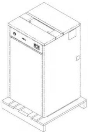
After the water and electrical connections have been prepared by a qualified technician, open the packing and remove the boiler from the pallet.
Once protective packing has been removed, be very careful not to damage the electrical and mechanical parts by bumping or splashing water.
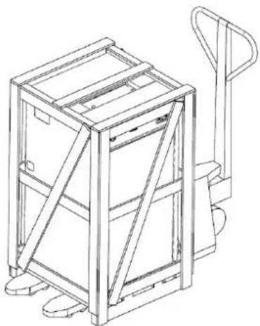
The boiler is delivered wrapped in nylon protection and packed on a pallet + wooden crate after completing the production cycle and the functional testing on the assembly line at the manufacturer's factory.
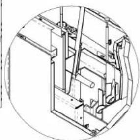
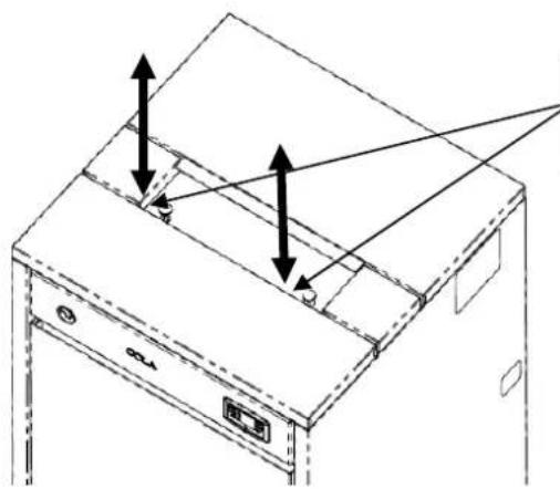
The boiler must be handled carefully, avoiding any bumping, always keeping it upright for transport and only using forklifts; alternatively, it can be handled from the top using a strap connected to a strong and secure hooking located internally and accessible by removing the two covers of the upper cladding and the cover as shown below, and inserting the strap inside the rectangular tube. Make sure the equipment used for lifting and transport can take the boiler's weight, specified on the data plate and in this manual.
Transport by trolley
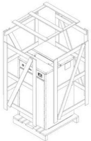
Unpacking the boiler
Boiler on packing base
Lifting by means of chain with hook.
Removing covers to fix the lifting strap.
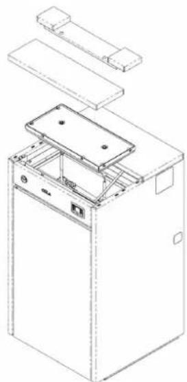
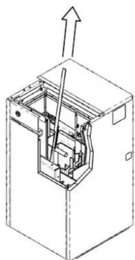
Lifting by means of strap with secure hooking.
Avoid taking the load in areas where it could be a danger if dropped.

- During transport and storage, avoid exposure to rain or persistent humidity.
- The boiler must only be moved in a vertical position by forklift, resting on the base.
- Use suitable equipment to remove the boards or wooden parts of the boiler packing.
- Disposal or recycling of the packing must be done by the end user, complying with local regulations on waste and keeping it out of the reach of children or disabled persons.
2.2 Place of installation, positioning and fire-prevention safety
After preparing the water and electrical connections (by a qualified technician), open the packing and remove the boiler from pallet.
After removing the protective packing, be careful not to damage the mechanical and electrical parts by knocking on splashing with water.
Place the boiler in the required location, making sure it:
- complies with the requirements of the regulations in force,
- complies with correct operation of the unit,
- is possible to operate and service the unit in any position needed to do the work,
- is provided with adequate ventilation from the outside,
- is provided with a suitable fume exhaust system,
- is provided with an approved, grounded power socket.
Set the boiler down on the floor very carefully without any bumping and position it in the required place. Make sure the floor can take its weight, otherwise see a specialized technician.
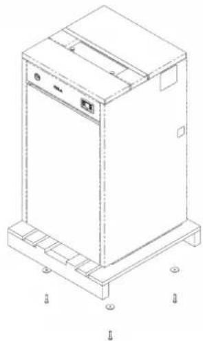
After positioning the boiler, fit the 4 feet (included the bag supplied) which stabilize the unit if the floor is not perfectly flat: to fit and/or adjust the height of each foot, tilt the boiler where and as necessary.

Positioning feet
The unit is suitable for operation in technical environments with min. temperature not below 0^ ; it comes complete with an antifreeze function that activates the heating pump for system water temperatures below 6^ , safeguarding: heating chamber, heating/DHW circuit. The antifreeze function is active only when the boiler is electrically powered.
The boiler must also be suitably separated from flammable or combustible materials by air spaces or the use of appropriate protective insulation; floors and/or ceiling-coverings in flammable or heat sensitive material must be protected by panels of insulating material.
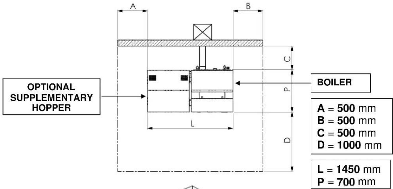
Make sure there are spaces at the sides and rear of the boiler, necessary for servicing and cleaning the unit, fume ducts and the flue.
Also make sure the pellet hopper is easily accessible for loading the fuel.
The minimum distances for maintenance and safety must comply with the following table:
In case of more than one heating unit in the same place, even fed with different fuels, as well as hoods with or without exhaust fan, installation must be checked by a specialized technician, considering that the boiler has a fume extractor installed on the lower fume manifold inside it.
Provide the appropriate air intakes for each of them according to the manufacturers' directions, in order to ensure the simultaneous operation of all units in the heaviest operating conditions.

- The boiler must not be installed where there are heating units that draw combustion air from the room in which they are installed, or from adjacent and adjoining rooms.
-Installation in places with danger of fire is forbidden.
2.3 Air inlet
The boiler must have the combustion air needed to ensure proper operation, through external air inlets, and specifically:
-a wall air inlet of at least of 100~cm^2 , communicating with the outside and suitably protected externally by a grille, must be provided near the boiler;
-or by connection directly to the outside with a suitable pipe of inside diameter 50mm and max. length 1.5 m suitably protected at the end.
- or through the room adjacent to that of installation provided the air is free to flow through permanent openings communicating with the outside, meeting the requirements described above. The adjacent room must not be subject to a lower pressure than the outside environment due to the draught effect created by the presence of other possible units or suction devices. The adjacent room can not be used as a car garage, for storing combustible material or for activities with fire risk.
The inlet connection or air intake (diam. 50 / 60mm round section) is located at the back of the boiler and is suitably protected by a grille incorporated in rear sheet metal and removable if necessary; it must also ensure a flow of clean air, free of pollutants, for regular combustion at maximum power.
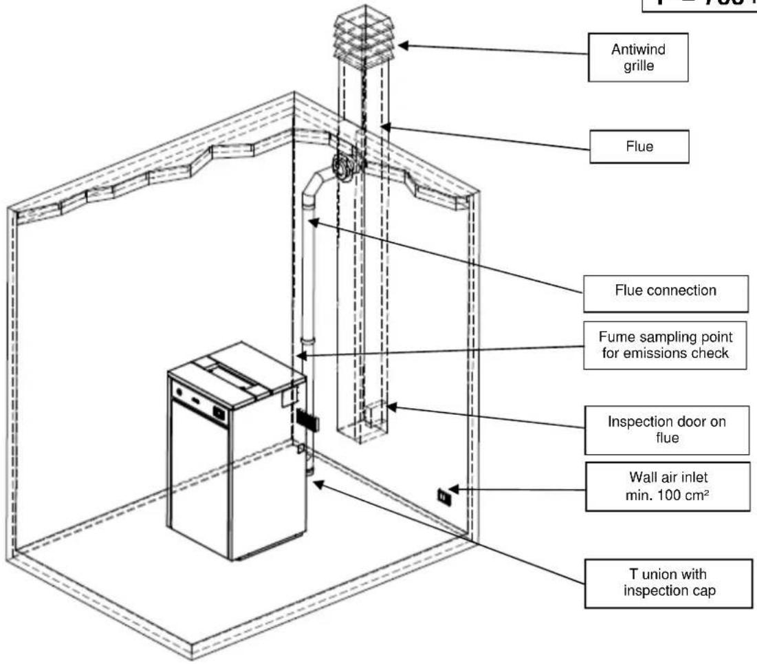
2.4 Fume exhaust
Fumes can be exhausted through a connection to an approved flue.

- The installer must check the efficiency and state of the flue and its conformity with the local, national and European regulations.
-Only certified pipes and connections with adequate seals guaranteeing their tightness must be used.
-Make sure there is an inspection device at the bottom of the flue for periodical checking and cleaning, to be done every year (compulsory).
-Make sure an approved antiwind cap is installed at the top of the flue.
-Flexible metal tubes or fibre cement pipes are prohibited.
-In case of fire, turn the boiler off, promptly call the fire department, and avoid continual attempts to extinguish it.
2.4.1 Types of installations
Listed below are definitions and requirements for correct installation of an exhaust flue in accordance with Italian Standard UNI10683:
FLUE: a vertical duct for collecting and expelling, at an appropriate height from ground, the fumes coming from a single unit and, where permitted, more than one.
FLUE technical requirements: - it must be fumetight, isolated and insulated depending on its use;
- it must have a mainly vertical path with axis deviation < 45^ ;
- it must be placed at a suitable distance from flammable materials by means of insulation or air gap;
- it must preferably have a continuous, free and independent round internal section;
- it is advisable for the flue to have an inspectionable chamber for the collection of solid materials
- and any condensate, placed under the beginning of the fume duct.
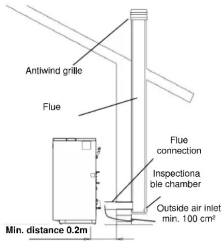
FLUE CONNECTION or DUCT: duct or connection element between the unit and flue for evacuation of fumes.
DUCT technical requirements: - it must not cross rooms where the installation of combustion units is not allowed;
- flexible metal tubes or fibre cement pipes are prohibited;
- the use of counter-sloping elements is prohibited;
- horizontal sections must have an upward slope of at least 3% ;
- the length of the horizontal section must be minimal and not more than 3m
- there must not be more than 3 changes of direction without the T union;
- with change of direction >90^ a max. of 2 bends can be used with length in horizontal projection not exceeding 2m .
- the fume duct must have a continuous section and allow the recovery of soot.
CHIMNEY CAP : a device placed on the top of the flue to facilitate the dispersion of fumes into the atmosphere.
CHIMNEY CAP technical requirements : - it must have a section equivalent to that of the flue;
- it must have a useful section not less than double the internal section of the flue;
- it must prevent the entry of rain and foreign bodies and ensure the discharge of fumes in any atmospheric condition;
- it must ensure an adequate dilution of fumes and be positioned outside the backflow area;
- it must be without mechanical means of suction.

- The direct discharge of fumes must take place on the roof and not towards closed spaces (even open air).
- Provide for a sampling point (airtight and easily removable) on the fume connection for periodical emissions checks.
2.5 Turbulator and brazier position check
Before lighting the boiler, make sure the brazier is in the correct position, i.e. fitted in the special slots. Also make sure the turbulator shaker device is resting in the lower position. An incorrect position of the brazier and/or turbulators can result in malfunctioning and excessive creation of dusts and unburnt products.

At every unit lighting, check the correct position of the brazier and turbulator shaker device.
2.6 Electrical connection
Connect one end of the power cable to the rear socket of the stove, and the other to a wall socket.
The voltage supplied by the system must match that specified on the stove data plate and in the technical data section of this manual.
During stove idle periods it is advisable to remove the power cable.

- Make sure the electrical system complies with the regulations and has an earth connection and differential switch in compliance with the current Standards
- The power cable must never touch the stove exhaust pipe.
2.7 Wiring diagram
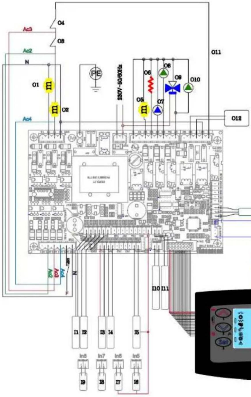
- Optional
| 01 | Fume extraction fan |
| 02 | Auger's motor |
| 03 | Thermostat safety pellet |
| 04 | Thermostat safety water |
| 05 | Auger's motor additional tank * |
| 06 | Igniter |
| 07 | Heating pump coupled to 3 ways valve 09 |
| 08 | Heating pump coupled to second pump 010 |
| 09 | Three ways motor valve * |
| 010 | Sanitary pump coupled to heating pump 08 * |
| 011 | Safety circuit |
| 012 | Boiler consent AUX * |
| I1 | Water probe safety boiler (S1) |
| I2 | Water probe heating (S2) |
| I3 | Fume probe |
| I4 | Room thermostat / Puffer heating thermostat * |
| I5 | Water pressure tranducer |
| I6 | Level pellet 1 |
| I7 | Level pellet 2 * |
| I8 | Water probe sanitary boiler (S3) * |
| I9 | Flowswitch / thermostat sanitary boiler * |
| I10 | BUS 1 * |
| I11 | BUS 2 * |
| I12 | Fume verifier encoder |
| I13 | Air flow meter |
2.8 Wiring diagram for zone system
Before installing the boiler in the home, check the type of heating system; if there are several zones, a special electronic controller for multi-zone circuits, available as an optional, must be installed. This is to prevent overheating of the unit due to possible simultaneous closing of the zone valves and consequent stopping of hot water delivery flow.
2.9 Plumbing connections
The heating capacity of the unit must be previously established by calculating the building's heat requirement according to current regulations, by contacting a specialised technician.
According to Italian Standard UNI 10412-2 (2009) and proper installation technique, a heating system must be provided with all the adjustment, control and safety components to ensure proper and safe operation, as well as shutoff and non-return valves to allow the boiler to be isolated from the system in case of maintenance and/or checks.
There are two types of systems: CLOSED VESSEL system and OPEN VESSEL system. In the present case, both types are compatible with our unit, provided all the adjustment, control and safety components required by the current regulations on installation are installed.
The pellet boiler has an internal heating water circuit complete with high efficiency circulating pump, safety valve, air vent, temperature probes and pressure transducer.
If the heating system is managed in zones a multi-zone controller, available on request, must be installed.
In solid fuel boilers, to avoid the return of cold water in the heating chamber during the heating phase, it is advisable to install an AUTOMATIC THERMOSTATIC VALVE (available on request) in the system to improve combustion efficiency and boiler life and also reduce the condensation of fumes in the flueways, with less deposits and tars.
Before connecting the boiler to the water circuit, thoroughly clean all system pipes to remove any residuals or machining residuals that could compromise the proper operation of the adjustment, control and safety components.

During boiler transport, the rings and respective seals in the water system may come loose and/or break, causing water leaks during operation; therefore make sure to check the tightening of the circulating pump and heating chamber connection rings and vent the residual air during water filling and after the first hours of operation.
2.9.1 System water filling
After carrying out the plumbing connections, it is possible to FILL the unit and system:
- open all the air vent valves of the radiators - manifolds - boiler and system;
- open the water filling cock gradually, making sure the vent valves work properly;
- fill the system slowly, to allow proper and complete evacuation of the air from the vent, bringing the circuit under pressure (for a closed vessel system from 1.1 to 1.5 bar);
- when finished, close the filling cock and make sure all vent valves have discharged the air from the system.
- to display the boiler's water circuit pressure, just press the control panel button P5 for 3 seconds.

The creation of a heating system with installation of the boiler must comply with all the applicable National, Regional, Provincial and Local regulations in the country where the system is installed.
2.9.2 System water characteristics
The chemical-physical characteristics of the system and replenishing water are important for the proper operation and service life of the boiler; in fact, with the use of low quality water the most frequent problem is due to scale, which causes a reduction in heat exchange and generates corrosion.
It is therefore advisable to check the water quality and, in the conditions listed below, provide for treatment:
- very hard water ( >20^ ),
- considerable amounts of replenishing water or subsequent fillings,
- systems of some complexity and size.
2.9.3 DHW system
To connect the boiler to a DHW system, it is advisable to see a qualified technician in order to best optimise the plumbing connections and the performance of the entire system without compromising unit functionality.
One of the following optionals must be requested for the connection to the DHW circuit:
- a DHW pump on the delivery manifold with respective connection pipes for placing inside the boiler.
- or a DHW pump, plate heat exchanger and connection pipes for placing inside the boiler.
- or a 3-way valve for installing outside the boiler.
- or hydraulic separation module to be installed outside the boiler.
After completing the DHW connection it is necessary to access the technical menu of the controller and select the type of circuit; every specific DHW function set: DHW EXCHANGER/ FLOW SWITCH, ACCUMULATOR (PUFFER) or DHW STORAGE TANK appears on the display at the moment of heating-DHW switchover with one of the messages and remains until the end of the DHW.
Hydraulic diagram - Pellet boiler with pump
Pellet boiler
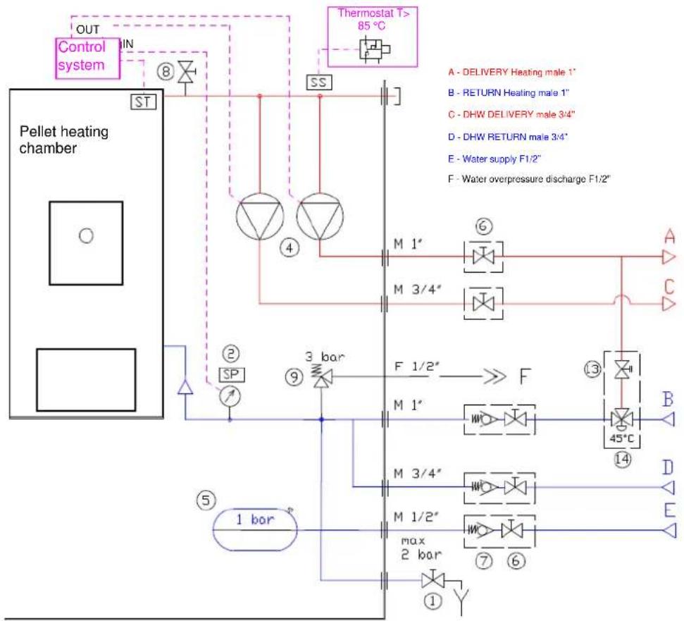
/KEY:
CLUEN

(1)
Pressure gauge/pressure sensor


Membrane expansion tank
5
Shutoff valve/cpck

Non-return valve
(7)Non-return value
Circuit heating chamber air vent

Pressure relief valve P max 3 bar

Pressure relief valve P max 6 bar

10
1 Flow switch

Plote-hot exchanger for DHW

Circuit balancing valves

Automatic thermostatic valve

Safety sensor T > 85^

Water temperature sensor

Circuit pressure sensor

qValves to be included in the system during installation - not supplied with the unit
Hydraulic diagram of pellet Boiler with DHW plate heat exchanger 07-2012
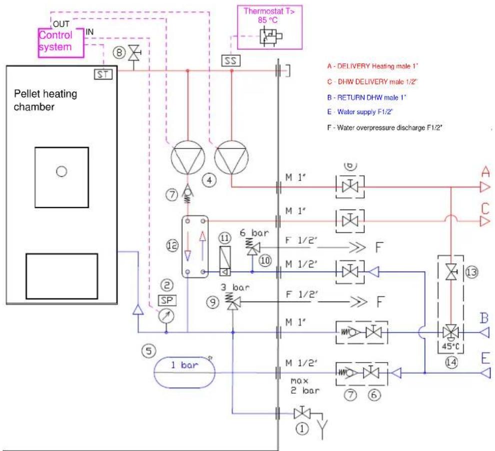
Pellet boiler
KEY:
1 Drain cock
Pressure gauge/pressure sensor
(4) Circulating pump
(5) Membrane expansion tank
Shutoff valve/cock
Non-return valve
Circuit/heating chamber vent
Pressure relief valve P max 3 bar
10Pressure relief valve P max 6 bar
11 Flow switch
Plate heat exchanger for DHW
Circuit balancing valves
Automatic thermostatic valve
Safety sensor T > 85°C
ST Water temperature sensor
SP Circuit pressure sensor
2.10 Emergency
Suitable fire-prevention devices should be arranged for any eventuality. In case of a fire, proceed as follows:

- Immediately disconnect the power plug;
- Extinguish the fire using suitable fire-extinguishers;
- Call the fire department immediately;
- Do not use jets of water to extinguish the fire.
3 BOILER SAFETY
3.1 Safety distance from flammable materials
To prevent the risk of fire, unit positioning must respect a minimum distance from flammable materials, according to that given in the technical table of the manual and on the data plate.
Pay attention to the type of floor and ceiling-covering in the place of installation: for delicate and flammable materials it is advisable to use adequate thermal diaphragms or panels (see par. 2.2).
3.2 Fume exhaust safety
In normal operation the combustion chamber is in a negative pressure, guaranteeing seal against any smoke leaks into the room. If a certain vacuum level is not reached or the fume exhaust outlet is blocked, the vacuum switch detects the lack of a negative pressure inside the combustion chamber or the air flow meter detects a lack of combustion air flow and, through the electronic controller, switches off the auger rotation motor, signalling the anomaly with a message on the control panel 'AL8 NO NEG PRESS' or 'AL9 INSUF DRAUGHT'.
3.3 Combustion chamber overpressure safety
Any and/or sudden combustion fume overpressures inside the chamber and fume exhaust ducts are discharged by opening of the safety valves located above the ash door. During normal operation these valves are kept closed by their weight and the negative pressure in the combustion chamber, ensuring a seal against any smoke escaping.

Periodically check closing, the integrity of the device and its operation.
3.4 Overheating - safety thermostats
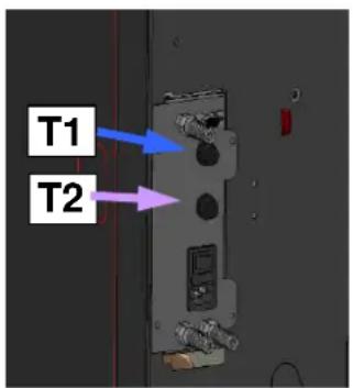
On the bottom of the hopper, and namely on the pellet chute and on the top part of the heating chamber, there are two temperature probes connected to the respective safety thermostats that automatically shut off the pellet supply in case of excessive heating. In this case the extractor and/or fans continue working, allowing the unit to cool down rapidly. The fault is displayed on the control panel with the message 'AL 7 THERMAL SAF'. In case of activation, proceed as follows:
- Allow the boiler to cool down for at least 45 minutes.
- Reset the thermostat by pressing the button near the switch behind the boiler (figure opposite) after removing the protection, and namely:
T1 - heating chamber water temperature thermostat
T2 - pellet chute temperature thermostat
- Restart the boiler normally.
Pellet hopper thermostat activation temperature : – > 85°C
Heating chamber thermostat activation temperature: > 95°C
3.5 Safety against flare-back in the pellet chute
The solutions preventing flare-back are:
- negative pressure in the combustion chamber see par. 3.2.
- the siphon shape of the pellet chute.
- the hopper temperature safety see par. 3.4.
3.6 Overcurrent protection device
The unit is protected against overcurrent by 2A fuse/s on the power supply of the main boiler switch located at the back.
3.7 Water circuit overpressure safety
Any overpressure of the water inside the chamber, by P > 3 bar, is discharged through activation of the safety valve installed in the hydraulic system inside the stove.

Do not tamper with the safety devices.
3.8 Fume extractor fan failure
If the fume extractor fan stops for any reason, the electronic controller instantly stops the pellet supply, displaying the message 'AL4 FAN FAIL'.
4 BOILER USE
4.1 Introduction
The pellet boiler has the advantage of combining the heat generated by the combustion of wood with the convenience of automatic water temperature management and the possibility of weekly programming of switching on/off, as well as the connection of a thermostat and/or chronothermostat and start-stop remote control.
For safe and reliable use:
- when lighting and using the unit the first time, unpleasant odours may be created, therefore air the room thoroughly;
- the hopper must only be filled with good quality pellets; make sure the bag does not come into contact with the hot surfaces of the boiler;
- do not put any fuel other than the prescribed pellets in the hopper;
- the unit must not be used as a waste incinerator;
- the boiler must only operate with the fire door always closed.
- the fire and ash door seals must be checked periodically to prevent air from entering;
- to ensure thermal efficiency and correct operation it is necessary to clean the brazier every time pellets are loaded;
- when lighting the boiler for the first time, allow it to heat up gradually by setting low operating temperatures (see the section on temperature setting);
- during lighting, operation and shutdown, the boiler may creak a little due to the heat expansion.
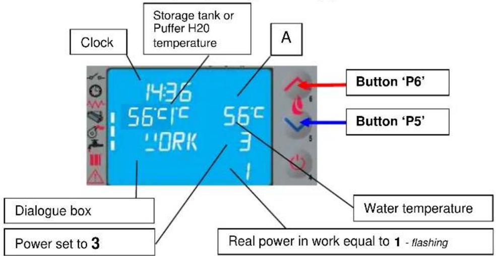
4.2 Description of control panel
The control panel comprises a backlit LCD, on/off button 'P4', SET/MENU button 'P3', four menu buttons 'P1', 'P2', 'P5', 'P6', and seven boiler operation status LEDs.
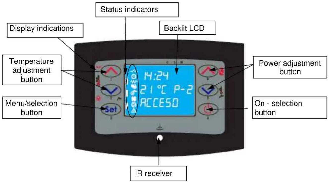
The panel enables boiler lighting and shutdown, adjustment during operation and the setting of management and maintenance programs.
The display shows all the information on boiler operation status.
To access the menus, proceed as follows:
- press the SET button 'P3';
- press the buttons 'P5', 'P6' to scroll the various menus;
- press one of the increase/decrease buttons 'P1', 'P2', to set the required parameter;
- press the SET button 'P3' to confirm the parameter value.
On accessing the menu it is possible to obtain the various types of displays and make settings, depending on the access level.
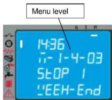
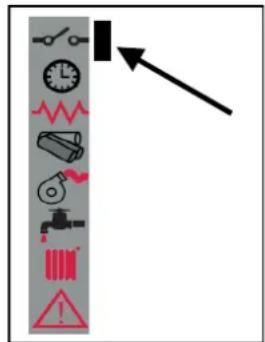
The Figure opposite describes the meaning of the status indicators in the left part of the display. Activation of one of the segments on the display signals activation of the corresponding device according to the list opposite.
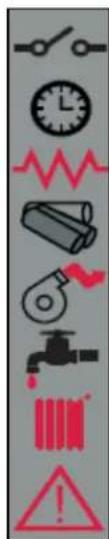
External contact
Chrono
Heater
Auger
Fume extractor
HEATING circuit activation
ALARM
4.3 Lighting
4.3.1 Check before lighting
Before lighting the boiler:
- make sure to have read and understood the information given in the manual;
- follow the oral instructions on operation of the unit provided by the installer prior to use.
- the hopper must be filled with pellets;
- the combustion chamber must be clean;
- the brazier must be completely free, cleaned of any combustion residuals and correctly fitted in the brazier holder:
- check hermetic closing of the ash box and fire door;
- check the connection of the power cable and switching to ON/1 of the switch located on the back of the boiler.
- check opening of the delivery and return shutoff valves as well as the water circuit pressure.

- At first startup, remove all the components that could burn (instructions/label) from the boiler firebox.
- Any lighting done after long idle periods requires the removal of any residual pellets that have remained inside the hopper, in being damp fuel no longer suitable for combustion, and complete cleaning of the combustion chamber.
4.3.2 Startup stage
To light the boiler, press the button 'P4' for 3 seconds: the message 'START' will appear on the display. This stage is automatic and managed entirely by the electronic controller without the possibility of changing the parameters.
Alternatively the boiler can be lit by pressing the buttons P4 and P5 together for 3 seconds. The message AWAITING REQUEST appears on the display. With this mode the boiler switches to standby status and carries out the lighting-start stage only if a request for heat is recognised, e.g. to heat the water or for DHW (if available).
The boiler carries out the startup stages in sequence according to the procedures defined by the parameters that manage levels and times, reaching the work condition unless anomalies or alarms occur, according to the following table:
| Status Devices | ||||
| igniter | Fume extr. | auger exch. | ||
| OFF | OFF OFF | OFF | OFF | |
| START - PREHEAT | ON | ON OFF | OFF | |
| PELLET PRELOAD | ON | ON | ON | OFF |
| AWAITING FLAME | ON | ON OFF | OFF | |
| PELLET LOADING | ON | ON | ON | OFF |
| FIRE PRESENT | OFF | ON | ON | ON |
| WORK | OFF | ON | ON | ON |
| WORK MODULATE | OFF | ON | ON | ON |
| BRAZIER CLEANING | OFF | ON | ON | ON |
| WORK | OFF | ON | ON | ON |
| FINAL CLEANING | OFF | ON OFF | ||
After a certain time has elapsed, if the fume temperature has not reached the permissible minimum value the boiler goes in alarm status.

-Do not use flammable liquids to light the unit.
-In case of persistent failed lighting, contact the Service Centre.
4.4 Work stage
After the 'STARTUP' stage, the boiler goes to the 'WORK' mode which is the normal operation mode. The user can adjust the heating power from the max. value of 5 to a min. of 1 with the buttons 'P5' and 'P6'. DHW circuit function activation ON is displayed by the segment/LED [A].

- Make sure to check the pellet level in the hopper so that the flame does not go out due to lack of pellets.
- Make sure the unit is off when loading pellets.
- The pellet hopper lid must always remain closed; it must only be opened when loading fuel.
- The bags of pellets must be kept at least 1.5m from the boiler.
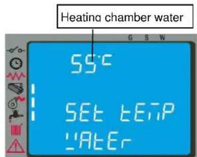
4.4.1 Modifying the water temperature setting
To modify the water temperature, press button P1 and then increase or decrease the temperature parameter with buttons P1 and P2.
When the water temperature has reached the set value, the power is automatically brought to the min. value, MODULATION status.
When the fume temperature reaches a set max. value the message 'MODULATE F' appears on the control panel and the stove activates the flame modulation procedure without any user intervention, whereas if the temperature exceeds 285^ the alarm 'AL3 HOT FUMES' appears and the boiler activates the shutdown procedure.
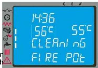
4.4.2 Cleaning the brazier
During normal operation in work mode, the 'BRAZIER CLEANING' mode is activated at parameter-fixed intervals for a set duration.
4.4.3 DHW with rapid heat exchanger
When hot water is required, the display shows the message DHW EXCH and The function is carried out only if the boiler is on, and the water inside the h temperature.
In the remaining cases the service is not provided.
lights up. sufficient
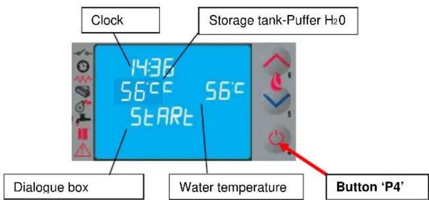
4.4.4 DHW with storage tank
This type of installation requires the use of an external thermostat or a water probe, which measures the DHW storage tank (puffer) temperature.
In the former case, temperature SETTING is obtained by adjusting the puffer thermostat controller.
In the latter case, to modify the temperature it is necessary to press button P2 on the control panel and then increase or decrease the temperature value with buttons P1 and P2.
The DHW function is activated when the temperature falls below the SET temperature. During the STANDBY phase, the boiler automatically lights and goes to WORK mode. Once the work temperature of the heating chamber water is reached, the supply of water to the storage tank (puffer) is activated. The boiler display shows the message DHW and the respective LED lights up.
When the SET temperature of the storage tank is satisfied, the BOILER activates the heating system. If there is no further demand, the boiler goes on STANDBY or to MODULATION, depending on the settings (see par. 4.6.2). If the boiler is in OFF status, it does not light and does not provide the service.
4.4.5 System with puffer / heat accumulator
This type of installation requires the use of an external thermostat or a water probe, which measures the puffer water temperature.
In the former case, temperature SETTING is obtained by adjusting the puffer thermostat controller.
In the latter case, to modify the temperature it is necessary to press button P2 on the control panel and then increase or decrease the temperature value with buttons P1 and P2.
When the temperature drops below the SET external thermostat temperature:
If the boiler is in the AWAITING REQUEST stage, it automatically turns on and goes to WORK status and the supply of water to the puffer is activated when the work temperature of the heating chamber water is reached. When the puffer SET temperature is met, the boiler goes to AWAITING REQUEST (make sure to set the STANDBY function to ON, see par. 4.6.2).
If the boiler is in OFF status, it does not turn on and does not provide the service.
It is possible to choose the temperature SETTING of the DHW storage tank and of heating from a min. of 54^ (STD pump start value) to a max. of 80^ with minimum return temperature not lower than (50 - 55)^ in order to prevent condensation inside the chamber.
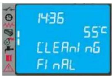
4.5 Shutting down
To shut down the boiler, just press the button 'P4' for about 2 seconds.
The auger is immediately stopped and the fume extractor is brought to high speed, making the message 'FINAL CLEANING' appear on the display.
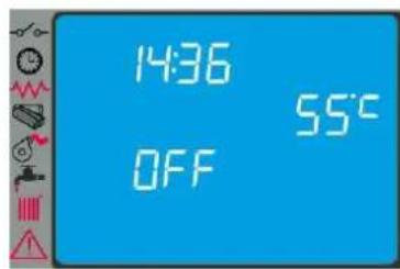
At the end of the operation the message'OFF' appears in the dialogue box.
During the shutdown stage the boiler cannot be restarted until the fume temperature has fallen below a set value for a fixed time, with the message 'WAITING COOL' appearing in the dialogue box.
At the end of the operation, the message 'OFF' will appear in the dialog box.
4.6 Menu
Press button 'P3' (SET) to access the menu; this is divided into various items and levels for accessing the settings of the electronic controller.
The following table summarises the menu structure with the selections available to the user.
| Menu Item Position Level 2 Menu Item Position Level 3 Parameter Name | Unit | ||||
| Menu 01 | M-1-1 Enable Chrono M-1-1-01 Enable Chrono On/Off | M-1-2-01 Day Chrono On/Off | |||
| M1-2 Day Program | M-1-2-02 Start 1 Day | ||||
| M-1-2-03 Stop 1 Day | |||||
| M-1-2-04 Start 2 Day | |||||
| M-1-2-05 Stop 2 Day | |||||
| M1-3 | Weekly Program | M-1-3-01 Week Chrono On/Off | |||
| M-1-3-02 Start Prog-1 | |||||
| M-1-3-03 Stop Prog-1 | |||||
| M-1-3-04 Monday Prog-1 | |||||
| M-1-3-05 Tuesday Prog-1 | |||||
| M-1-3-06 Wednesday Prog-1 | |||||
| M-1-3-07 Thursday Prog-1 | |||||
| M-1-3-08 Friday Prog-1 | |||||
| M-1-3-09 Saturday prog-1 | |||||
| M-1-3-10 Sunda/Prog-1 | |||||
| M-1-3-11 Start Prog-2 | |||||
| M-1-3-12 Stop Prog-2 | |||||
| M-1-3-13 Monday Prog-2 | |||||
| M-1-3-14 Tuesday Prog-2 | |||||
| M-1-3-15 Wednesday Prog-2 | |||||
| M-1-3-16 Thursday Prog-2 | |||||
| M-1-3-17 Friday Prog-2 | |||||
| M-1-3-18 Saturday prog-2 | |||||
| M-1-3-19 Sunday Prog-2 | |||||
| M-1-3-20 Start Prog-3 | |||||
| M-1-3-21 Stop Prog-3 | |||||
| M-1-3-22 Monday Prog-3 | |||||
| M-1-3-23 Tuesday Prog-3 | |||||
| M-1-3-24 Wednesday Prog-3 | |||||
| M-1-3-25 Thursday Prog-3 | |||||
| M-1-3-26 Friday Prog-3 | |||||
| M-1-3-27 Saturday prog-3 | |||||
| M-1-3-28 Sunda/Prog-3 | |||||
| M-1-3-29 Start Prog-4 | |||||
| M-1-3-30 Stop Prog-4 | |||||
| M-1-3-31 Monday Prog-4 | |||||
| M-1-3-32 Tuesday Prog-4 | |||||
| M-1-3-33 Wednesday Prog-4 | |||||
| M-1-3-34 Thursday Prog-4 | |||||
| M-1-3-35 Friday Prog-4 | |||||
| M-1-3-36 Saturday Prog-4 | |||||
| M-1-3-37 Sunda/Prog-4 | |||||
| M1-4 | Week-End Program | M-4-2-01 Week-End Chrono Start 1 Week-End | |||
| M-4-2-02 Stop 1 Week-End | |||||
| M-4-2-03 Start 2 Week-End | |||||
| M-4-2-05 Stop 2 Week-End | |||||
| Menu 02User adjustments | M-2-1 | Set Clock | |||
| M-2-2 | Standby mode | On/Off | |||
| M 2-3 | Initial load | On | |||
| M 2-4 | Pellet type | Pellet adjustment | (-9 - +9) | ||
| M 2-5 Initial load auger 2 | On | ||||
| Menu 03User settings | M-3-1 | Language | -- | ||
| M-3-3 | Buzzer mode | On/Off | |||
| M-3-4 | Lighting | (0 - 100) | |||
| M-3-6 | Heating Delta | (0.5 - 20) | |||
| M-3-7 | Storage tank-Puffer Delta | (0.5 - 20) | |||
| M-3-8 | Pellet level | On/Off | |||
| M-3-9 | DHW control | ON/OFF/EST | |||
| Menu 04Boiler status | menu for technician | ||||
| Menu 05technician settings | menu for technician | ||||
| Menu 06Installer settings | menu for technician | ||||
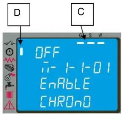
4.6.1 Menu 01 - Chrono setting
Allows all chronothermostat functions to be enabled/disabled; select ON to activate the function and display the relevant segment/LED [D]
When Daily, Weekly or Week End programming is entered, the appropriate segment/LED [C] appears in the top right of the display.
Regarding selections and entering times, use the buttons according to the table in par. 4.2.
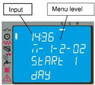
By accessing the submenu: DAY PROGRAM, the daily chronothermostat functions can be enabled/disabled and set. It is possible to set two operation stages delimited by the times set according to the following table where the setting OFF tells the clock to ignore the command.
| Selection Meaning | Possible Values | |
| START1 activation | time time - OFF | |
| STOP1 deactivation | time time - OFF | |
| START2 activation | time time - OFF | |
| STOP2 deactivation | time time - OFF |
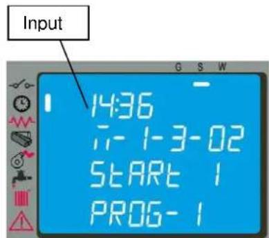
By accessing the submenu: WEEK PROGRAM it is possible to enable/disable and set the weekly chronothermostat functions. The weekly programmer has 4 independent programs whose final effect consists of a combination of the 4 programmmings.
The weekly programmer can be activated or deactivated; also, by setting OFF in the time field, the clock ignores the corresponding command.

Carry out programming making sure not to overlap the hours of activation and/or deactivation on the same day in different programs.
By accessing the submenu: WEEK-END PROGRAM it is possible to enable/disable and set the week-end (Saturday - Sunday) chronothermostat functions.

Activate WEEK-END programming only after deactivating the weekly programming.
To avoid unwanted startup and shutdown operations, only activate one program at a time.
Deactivate the daily program if the weekly program is required; with this setting it is advisable to deactivate the week-end program.
4.6.2 Menu 02 - User adjustments
With this menu it is possible to do a number of settings as follows
- Set clock
Before operating with the boiler, it is necessary to set the current time and date so that there is a reference for possible chrono programming. The electronic controller has a lithium battery, model CR2032 3 Volt, giving the internal clock an autonomy of more than 4-5 years; with the boiler off, whenever the clock does not keep the time, or a series of zeros is displayed at restart, the battery must be replaced by calling an authorised service centre.
- Standby mode
On activating this function, the boiler shuts down automatically after the water temperature has remained above the SET value for a fixed time.
The next automatic relighting will be possible only when the temperature falls below the SET temperature by a given value entered in the parameters table.
Manual commands from the control panel have priority over programming.
With the selection OFF the boiler does not activate the STANDBY mode and functions normally activating the MODULATION function when the temperature exceeds the SET value.
-Initial load
Setting this function allows activation of gearmotor operation, with the boiler off or cold, for pellet preloading of 90 sec. It starts with button P1 and stops with button P4.
- Pellet type
With the function on, press the buttons P1 or P2 to increase or reduce pellet loading to optimise consumption and combustion, depending on the type of pellets used.
- Initial load auger 2
Setting this function allows activation of gearmotor operation relevant to the supplementary hopper for a fixed time. It starts with button P1 and stops with button P4.
4.6.3 Menu 03 - User setting
With this menu it is possible to carry out the following settings:
- Language
With this selection it is possible to select the dialogue language from those available entered in the menu, and
namely:ITALIAN-FRENCH-ENGLISH-GERMAN-SPANISH
- Buzzer
With this selection it is possible to activate/deactivate boiler acoustic signalling.
- Lighting
With this selection it is possible to change the brightness of the backlit display from a minimum of 0 to a maximum of 100.
- Heating Delta
With this selection, it is possible to set:
- the range between the SET temperature and the actual boiler shutdown temperature;
- the range between the SET temperature and the actual boiler relighting temperature.
This range can be set from a min. of 0.5^ to a max. of 20^ depending on the customer's needs and/or the type of system.
- Boiler/Puffer Delta
With this selection, it is possible to set:
the range between the SET temperature and the actual boiler relighting temperature.
This range goes from a min. of 0.5^ to a max. of 20^ depending on the customer's needs and/or the type of system.
- Pellet level
With the selection set to ON, the no pellets signal can be managed with:
-
a message on the panel 'NO PELLETS';
-
management of a supplementary pellet hopper (available on request).
With the selection OFF, the possible supplementary hopper is disabled and no message appears on the panel.
- DHW control
The selection ON allows to manage DHW from the storage tank or heat exchanger through the signal from the thermostat or flow switch.
The selection EST allows domestic hot water to be controlled in the summer (with heating off), via the signal from thermostat or probe. Selecting this item enables operation of just the DHW branch; standby is forced to ON and post-circulation follows that set in the menu M-6-9.
The summer function can be displayed only if the menu M-6-8 is set to T-PUFFER or S-PUFFER.
4.6.4 Menu 04 - boiler status
With this selection it is possible to display the instantaneous boiler status giving the operating status of the various devices connected to it; various pages placed in succession are available for monitoring.
4.6.5 Menu 05 - Technician settings
This selection is reserved for the COLA service centre authorised technician.

Modification of the technical parameters of menu 05 must be done by authorised and competent personnel; any changes made at random can cause serious damage for which COLA declines any liability.
4.7 Thermostat - external chronothermostat
To use an external thermostat, contact an authorised technician and for installation proceed as follows:
- turn off the power by the main switch on the back and unplug the power cable;
- remove the side panelling to access the electronic controller;
- referring to the wiring diagram, connect the two thermostat wires to the respective board TERM terminals;
- refit everything and check correct operation.
All the menu functions do not change for each of the settings and signalling of the connection occurs with lighting up of the segment LED on the status bar of the display. If met, the thermostat shuts down the boiler, displaying the STANDBY function on the panel (if on).

If an external thermostat-chronothermostat is used, it is advisable to deactivate the STANDBY mode and deactivate the control unit CHRONO programming.
Activation of the external thermostat-chronothermostat is signalled by lighting up of the status bar segment LED on the display.
If met, the thermostat shuts down the boiler, displaying the STANDBY function on the panel (if on).
4.8 Idle period (end of season)
If the boiler is not used for long periods, and/or at the end of each season, it is advisable to proceed as follows:
- remove all the pellets from the hopper;
- disconnect the power supply;
- clean thoroughly and, if necessary, have any damaged parts replaced by qualified personnel;
- protect the boiler from dust with suitable covering;
- store in a dry and safe place protected from atmospheric agents.
5 BOILER CLEANING
Boiler cleaning is very important to prevent: poor combustion, deposits of ash and unburnt products in the brazier, reduced thermal efficiency.
The boiler must only operate with the ash and fire door always closed.
The door seals must be checked periodically to prevent air from entering and ensure combustion chamber low pressure.
Routine cleaning is normally carried out by the customer following the instructions in the manual, whereas extraordinary maintenance, at least once a year, must be performed by the authorised Service Centre.

- Cleaning operations for all parts must be carried out with the boiler unplugged and cold;
- Dispose of cleaning waste in accordance with the current local regulations;
- The boiler must not be operated without its cladding;
- Avoid the creation of smoke and unburnt products during lighting and/or normal operation.
Given below are the control and/or maintenance operations for correct boiler use and operation.
| Parts / Period Type of cleaning | 1 day routine cleaning | 2-3 days routine cleaning | 1 month routine cleaning | 2-3 months routine cleaning | 1 year extraordinary cleaning: carried out by the Service Centre |
| Brazier | |||||
| Ash compartment-box | |||||
| Heating chamber tube bundle | ■ | ■ | |||
| Manifold - fume extractor | ■ | ■ | |||
| Ash-fire door seal | ■ | ||||
| Pipe - flue connection | ■ |
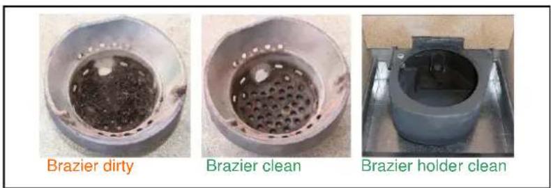
5.1 Cleaning the brazier - brazier holder
Remove the brazier and the ash deposited in the combustion chamber and brazier holder. A suitable vacuum cleaner may be used for this purpose. This operation must be carried out daily, especially in case of accumulated unburnt matter, to ensure perfect combustion conditions, since the brazier holes allow the flow of combustion air.
Also make sure the secondary air holes in the side pipes of the brazier holder are free of any combustion residuals and ash.
When necessary, clean the fire door glass for visually checking the flame inside the combustion chamber.

The brazier must rest on the brazier holder and precisely on the entire ring band without air gaps.
5.2 Cleaning the ash container
The ash container is located directly under the brazier - brazier holder. To clean it, open the ash door and remove the ash and any combustion residuals using a suitable vacuum cleaner.
The door must be closed after cleaning. The ash container can be cleaned every 2-3 days depending on boiler use.
5.3 Cleaning the fume extractor and combustion chamber
The combustion chamber must be cleaned at least once a year, removing all combustion residuals from the internal fume pipes and flueways. To carry out this operation, it is necessary to remove the boiler top cover, the heating chamber cover and the bottom inspection door, undoing the respective fixing screws, then clean the turbulators and internal fume pipes.
Also, make sure to clean the fume extractor located at the back of the bottom fume manifold accessed through the inspection door opening behind the ash box.
Every 3-4 months clean the inside walls of the combustion chamber and top fume manifold using suitable equipment (brushes) and replace the vermiculite walls if necessary.
Every 1800 hours of operation by means of a message 'SERVICE DUE', the boiler signals the need for extraordinary maintenance (not under warranty) to be performed by qualified personnel who will carry out complete cleaning and reset the message.

Any knocking or forcing can damage the fume extractor, making it noisy during operation; therefore it is advisable to have this operation carried out by qualified personnel.
5.4 Cleaning the air flow meter
The air flow meter (it measures the flow of combustion air) installed inside the inlet pipe requires periodical internal cleaning every 3-4 months, using suitable equipment (blowing compressed air or suitable brushes).
5.5 Cleaning the flue - flue connection
The flue connection must be cleaned at least once a year or whenever necessary.
Cleaning requires the suction and removal of the residuals in all the vertical and horizontal sections as well as the bends from the unit to the flue.
It is advisable to also clean the flue every year, to ensure correct and safe evacuation of fumes.
5.6 Cleaning the exchanger with turbulator-shaker device
The fume ducts inside the heating chamber must be cleaned at least once every 2-3 days by operating the two knobs repeatedly with an upward and downward movement.

- Do this with the boiler off and cold.
- At the end of the operation make sure the turbulators are in the rest position on the lowest level.
RH-LH control knobs of the turbulatorshaker device in boiler operation low position.
6 MAINTENANCE
6.1 Introduction
Operations on the internal parts of the boiler must be carried out by qualified personnel. Contact the nearest authorised service centre.

Make sure the boiler is unplugged and cold before carrying out any work on it.
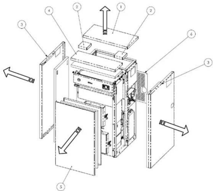
6.2 Removing the boiler cladding
Key:
1-Pellet hopper door
2- Central middle covers
3- Side panel
4-Front cover
5- Insulated outer door
6-Rear panel
6.3 Boiler internal parts
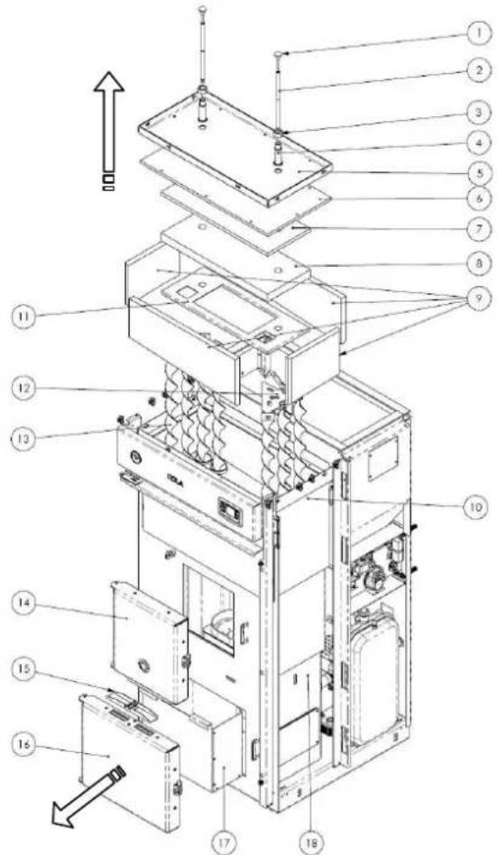
Key:
1-Knob with threaded rod
2-Turbulator-shaker device extension pin
3-Bush locking nut
4- Pin sliding bush
5- Outer cover
6- Upper thermal protection
7- Middle protection
8-Vermiculite upper protection
9-Vermiculite side protection
10-Chamber outer thermal protection
11-Protection support cover
12-Turbulator support
13-Turbulators
14-Fire door
15-Safety valve
16-Ash door
17-Ash box
18-Heating chamber
Exploded views of:
1-Brazier assembly
2-Fume extractor assembly
3-Auger assembly
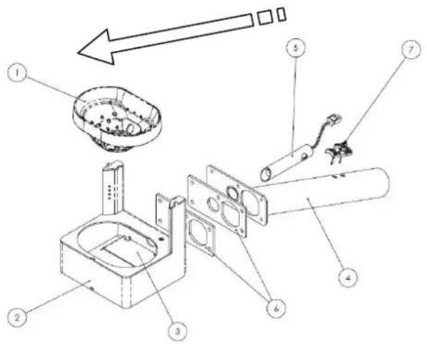
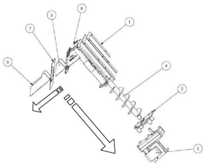
Key:
1-Brazier
2-Brazier holder
3- Internal baffle
4-Air inlet pipe
5- Heater
6-Seals
7-Air flow meter
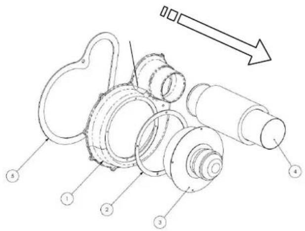
Key:
1-Fume extractor coil
2- Thermal seal
3-Fume extractor motor
4-Fume exhaust pipe
5- Seal
Key:
1- Conveyor - hopper seal
2-Gearmotor support flange
3 - Gearmotor
4-Auger
5- Seal for chute
6-Pellet chute
7- Conveyor-chamber seal
8-Pellet conveyor
6.4 Electrical components
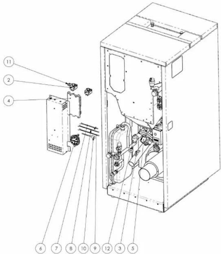
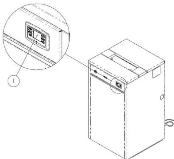
Key:
1- Control panel EVO model
2-Temperature safety thermostats
3-Air flow meter
4-Electronic board
5-Gearmotor
6-Vacuum switch
7-Fume probe
8- Heating chamber water probe
9 - Puffer-storage tank water probe
10-Level probe on pellet hopper
11-Serial connection
12-Pressure transducer
6.5 Standard hydraulic components
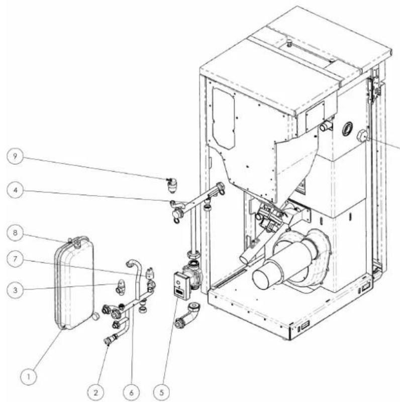
Key:
1-Membrane expansion tank
2- System drain cock 12
3- Pressure relief valve
4- Delivery pipe with connections 1"
5-Hight efficiency circulating pump
6- Return pipe with connection 1"
7-Pressure transducer
8- System filling connection 12
9- Boiler system air venting valve
10- Cap for thermal safety OPT
7 TROUBLESHOOTING
7.1 Alarm management
Alarms are indicated by an acoustic signal (if activated) and a message on the control panel.
In case of an alarm, shut down the boiler, eliminate the cause and restart the boiler according to the normal procedure described in this manual.
Every alarm status causes immediate boiler shutdown.
The alarms, with causes and cures, which can appear on the control panel are listed below:
| ALARMS - MESSAGES | |||
| Signalling Fault Possible causes Cures | |||
| AL 1 POWER FAILURE | -The boiler does not start. | -No power during the lighting stage. | -Turn the boiler OFF by pressing the button P4 and repeat the lighting procedure.-Other reinstatement operations must be carried out by a service centre. |
| AL 2 FUME PROBE | -Occurs in case of a fume temperature probe fault.-The shutdown procedure is activated. | -Probe fault.-The probe is disconnected from the board. | -Reinstatement operations must be carried out by a service centre. |
| AL 3 HOT FUMES | -Occurs if the fume probe detects a fume temperature above 280°C.-The shutdown procedure is activated. | -Too many pellets.-Reduced heat exchange in the system. | -Adjust the pellet flow.-Other reinstatement operations must be carried out by a service centre. |
| AL 4 FAN FAIL | -Occurs when the fume extraction fan is faulty.-The shutdown procedure is activated. | -The fume fan is blocked.-Faulty speed control sensor.-No power to fume fan. | -Reinstatement operations must be carried out by a service centre. |
| AL 5 NO IGNITION | -No flame in ignition stage.-The shutdown procedure is activated. | -The pellet hopper is empty.-The heater is faulty, dirty or not correctly positioned.-Pellet load setting incorrect. | -Check pellets in hopper.-Check the lighting procedures.-Other reinstatement operations must be carried out by a service centre. |
| AL 6 NO PELLETS | -Brazier not fed with pellets. | -The pellet hopper is empty.-The pellet loading gearmotor has to adjust.-The gearmotor does not load pellets. | -Check pellets in hopper.-Adjust the pellet flow.-Other reinstatement operations must be carried out by a service centre. |
| AL 7 THERMAL SAF | -Occurs in case of cutting in of the auger duct temperature safety thermostat.-The system is stopped. | -The safety thermostat has detected a temperature above the setting threshold due to overheating of the bottom part of the hopper blocking gearmotor operation. | -Check the cause of excessive overheating.-Reset the relevant safety thermostat by pressing the reset button. |
| Signalling Fault Possible causes Cures | |||
| AL 8NO NEG PRESS | -In the work stage the boiler detects a pressure below the vacuum switch setting threshold.-The system is stopped. | -The combustion chamber is dirty.-The fume duct is obstructed.-The fire door is not closed.-The overpressure valves are open-stuck.-Faulty vacuum switch. | -Check cleanness of the fume duct and combustion chamber.-Check hermetic closing of the door.-Check closing of the overpressure valves.-Other reinstatement operations must be carried out by a service centre. |
| AL 9INSUFFDRAUGHT | -Appears when the combustion air flow is below a certain threshold. | -The combustion chamber is dirty.-The fume duct is obstructed.-The fire door is not closed.-The overpressure valves are open-stuck.-Faulty air flow meter. | -Check cleanness of the fume duct and combustion chamber.-Check hermetic closing of the door.-Check closing of the overpressure valves.-Other reinstatement operations must be carried out by a service centre. |
| AL E WATER PRESSURE | -Occurs when the water pressure does not come within the values for correct operation.-The system is stopped. | -Occurs when the pressure transducer on the water circuit detects a pressure below or above the fixed limits. | -Check the cause of the problem, restoring the circuit pressure by bringing it to the normal operating value. |
| AL A SAFETY H2O | -Occurs in case of cutting in heating chamber water temperature safety thermostat.-The system is stopped. | -The safety thermostat has detected a temperature above the setting threshold due to overheating of the heating chamber water blocking gearmotor operation. | -Check the cause of excessive overheating.-Reset the relevant safety thermostat by pressing the reset button. |
| AL B AUG TRIACERROR | -Occurs when the gearmotor works continuously and for more than 60 sec.-The system is stopped. | -The controller detects a faulty gearmotor control relay (contacts stuck). | -Reinstatement operations must be carried out by a service centre. |
| AI C WATER PROBE S1 | -Occurs in case of water T detection probe fault, displaying T H2O = 0 °C.- The shutdown procedure | -Faulty probe.-The probe is disconnected from the board. | -Reinstatement operations must be carried out by a service centre. |
| AL F HOT WATER S1 | -Occurs when the water temperature has exceeded the fixed limits.-The system is stopped. | -Occurs when the temperature probe in the heating chamber detects a value above 92°C. | -Check the cause of the problem, restoring the temperature by bringing it to the normal operating value. |
| AI G WATER PROBE S2 | -Occurs in case of water T detection probe fault, displaying T H2O = 0 °C.- The shutdown procedure is activated. | -Faulty probe.-The probe is disconnected from the board. | -Reinstatement operations must be carried out by a service centre. |
| AL I HOT WATER S2 | -Occurs when the water temperature has exceeded the fixed limits.-The system is stopped. | -Occurs when the temperature probe in the heating chamber detects a value above 92°C. | -Check the cause of the problem, restoring the temperature by bringing it to the normal operating value. |
| AI H WATER PROBE S3 | -Occurs in case of water T detection probe fault, displaying T H2O = 0 °C.- The shutdown procedure is activated. | -Faulty probe.-The probe is disconnected from the board. | -Reinstatement operations must be carried out by a service centre. |
| AL d HOT WATER S3 | -Occurs when the water temperature has exceeded the fixed limits.-The system is stopped. | -Occurs when the temperature probe in the heating chamber detects a value above 92°C. | -Check the cause of the problem, restoring the temperature by bringing it to the normal operating value. |
| AWAITING COOL | -Occurs on relighting the boiler immediately after having shut it down. | -Reset attempt in shutdown stage with boiler hot in cooling stage. | -Alarm reset is possible only after shutdown. |
| AIRFLOW METER FAILURE | -Occurs when the air flow meter is disconnected. | -The controller does not detect the amount of combustion air and does not shut down the boiler; it only excludes the air flow meter functions. | -Reinstatement operations must be carried out by a service centre. |
| FROST RISK | -Occurs when the water temperature falls below a certain value. | -The boiler controller detects the water temperature below 6°C and displays a message. | -The pump starts in order to move the water inside the heating circuit.- Monitor the water temperature so that it does not fall below 0°C. |
| SERVICE DUE | -Occurs when the boiler has exceeded 1800 hours of operation since the previous servicing. | -Extraordinary maintenance notice. | -Cleaning - extraordinary maintenance and reinstatement operations must be carried out by an authorised service centre. |
The Manufacturer reserves the right to make technical or aesthetic changes to the products at any time without notice. The drawings, measurements, diagrams and any other configurations are given only by way of example.
8 INSTALLER
8.1 Menu installer settings
The following instructions are intended only for technical personnel specialised in heating units manufactured by COLA.

Changing the parameters in a non-appropriate way can cause serious damage to people, the units and the environment. In this case, Cola s.r.l. declines any liability.
To access the INSTALLER SETTINGS menu, press button P3 - MENU and use the scroll buttons to display the item INSTALLER SETTINGS and then press button P3 - MENU. Use the scroll buttons to display access key 10 and press button P3 - MENU.again.
The various parameters can be displayed with the scroll buttons; access with button P3 - MENU, edit them with the scroll buttons and exit with ESC.
It contains the adjustment parameters given below.
| Parameter code | Default Description | |
| M-6-1 0 | For increasing | or decreasing auger OFF duration for all powers. |
| M-6-2 0 | For increasing or decreasing fume extractor speed for all powers, by a value of 5% for each unit. | |
| M-6-3 OFF Enable key lock. | ||
| M-6-4 | 2°C | Adjustment probe temperature setting ON/OFF delta (see parameter M-6-7) |
| M-6-5 | 2 min. | Stove shutdown delay. Valid only in case of Standby set to ON. |
| M-6-6 OFF For enabling self-calibration. | ||
| M-6-7 | S-ACQUA | Allows the choice of sensor for setting boiler adjustment (heating branch) O045: Remote graphic display with incorporated room sensor T-AMBIEN: 'normally open' type external room thermostat T-PUFFER: 'normally open' type external thermostat on the hot water storage tank (puffer) S-ACQUA (S2): External probe on the delivery (default) or puffer and connected to the main board |
| M-6-8 OFF | Allows the choice of sensor for setting boiler adjustment (DHW branch) OFF : DHW control deactivated FLUSSOST: Flow switch on the DHW line of the rapid heat exchanger and connected to the main board (active only with boiler on in work phase) T-BOILER: 'Normally open' type external thermostat on the hot water storage tank (puffer) (SUMMER control activatable by the user) S-BOILER (S3): External probe on the hot water storage tank (puffer) and connected to the main board. (SUMMER control activatable by the user) | |
| M-6-9 | HEATING | Allows setting of post-circulation (dissipation of residual heat in the boiler) in summer mode RISC: heating branch SANI: DHW branch |
| M-6-A | OFF Enables or disables the additional tank | |
| M-6-B | OFF | Enables or disables activation of the external boiler when the pellet-fired boiler goes in alarm status |