
Mecablitz M400 - Flash METZ - Free user manual and instructions
Find the device manual for free Mecablitz M400 METZ in PDF.

| Product type | Cobra flash |
| Brand | Metz |
| Model | Mecablitz M400 |
| Dimensions (H x W x D) | Approx. 65 x 94.1 x 86.8 mm |
| Weight (without batteries) | Approx. 220 g |
| Power supply | 4 AA batteries (NiMH, alkaline or lithium) |
| Max. guide number (ISO 100/21°, zoom 105 mm) | 40 m (131 ft) |
| Flash modes | AUTO, TTL, TTL HSS, M, M HSS, LED, Master/slave remote, Servo |
| Synchronization | 1st/2nd curtain, high-speed HSS |
| Exposure compensation | -3 to +3 EV in 1/3 steps |
| Head tilt/swivel | Vertical: -9° to 90°; Horizontal: 60° to 180° (left/right) |
| Motorized zoom | 24-105 mm (12 mm with wide-angle diffuser) |
| LED video light | 100 lx at 1 m, intensity 1/1 to 1/32 |
| Color temperature (flash) | Approx. 5600 K |
| Display | OLED screen |
| Wireless functions | Master/slave, 4 channels, 2 groups (RMT, RMT2) |
| Firmware update | Via USB (micro) port |
| Care and cleaning | Soft dry or slightly damp cloth; do not spray liquid |
| Safety | Do not use near flammable gases; avoid direct flashes in eyes |
| Optional accessories | Mecabounce MBM-04, S60 stand, Easy Softbox ESB 60-60 |
Frequently Asked Questions - Mecablitz M400 METZ
User questions about Mecablitz M400 METZ
0 question about this device. Answer the ones you know or ask your own.
Ask a new question about this device
Download the instructions for your Flash in PDF format for free! Find your manual Mecablitz M400 - METZ and take your electronic device back in hand. On this page are published all the documents necessary for the use of your device. Mecablitz M400 by METZ.
USER MANUAL Mecablitz M400 METZ
natural_image
Black M400 camera flash unit with visible lens and control buttons (no text or symbols on body)www.metz-mecatech.de
Vorwort 4
9.3 mecabounce Diffuser MBM-04....21
flowchart
graph TD
    A["Directional Icon"] --> B["> Gear Icon"]
    B --> C{Opt.}
    C --> D["ZOOM STANDBY"]
    D --> E{Zoom Level}
    E --> F["ZOOM"]
    F --> G["28mm 35mm 50mm"]
    G --> H{Zoom Level}
Abmaße in mm (B x H x T):
- Easy Softbox ESB 40-40
(Bestellnr. 009014047)
REMOTE MASTER, chap. 10.1
REMOTE SLAVE, chap. 10.2
SERVO, chap. 10.3
F1 / F2, chap. 7.6
3.5 Le menu OPTIONEN
Réglage du mode
- Easy Softbox ESB 40-40
12.1 Indirect flitsen
Afmetingen ong. in mm (B x H x D):
Ca. 65 x 94,1 x 86,8
Gewicht :
- Easy Softbox ESB 40-40
(Bestelnr. 009014047)
Afmetingen: 40 × 40 cm
1 Safety instructions....136
2 Dedicated flash functions ..... 138
3 Preparing the flash unit for use....139
3.1 Power supply 139
3.2 Mounting the flash unit 140
3.3 Switching the flash unit on and off 140
3.4 The selection menu....140
3.5 The OPTIONS Menu 141
3.6 INFO 141
3.7 Auto OFF for the flash unit 141
4 OLED displays on the flash unit ..... 142
4.1 Flash readiness indication ..... 142
4.2 Correct exposure indication 142
5 Information in Display 143
5.1 Display of the flash mode.....143
5.2 Range display 143
5.2.1 Range display in TTL- and TTL HSS flash modes.....143
5.2.2 Range display in manual flash mode ..... 144
5.2.3 Exceeding the display range 144
6 Displays in the camera viewfinder ..... 144
7 Flash modes....145
7.1 AUTO Flash Mode 145
7.2 Preflash TTL and ADI metering 145
7.3 Manual flash mode 146
7.4 Automatic high-speed synchronisation (HSS) ..... 147
7.5 LED Video Light 148
7.6 Favorite programme....149
8 Manual flash exposure correction....150
9 Special functions ..... 151
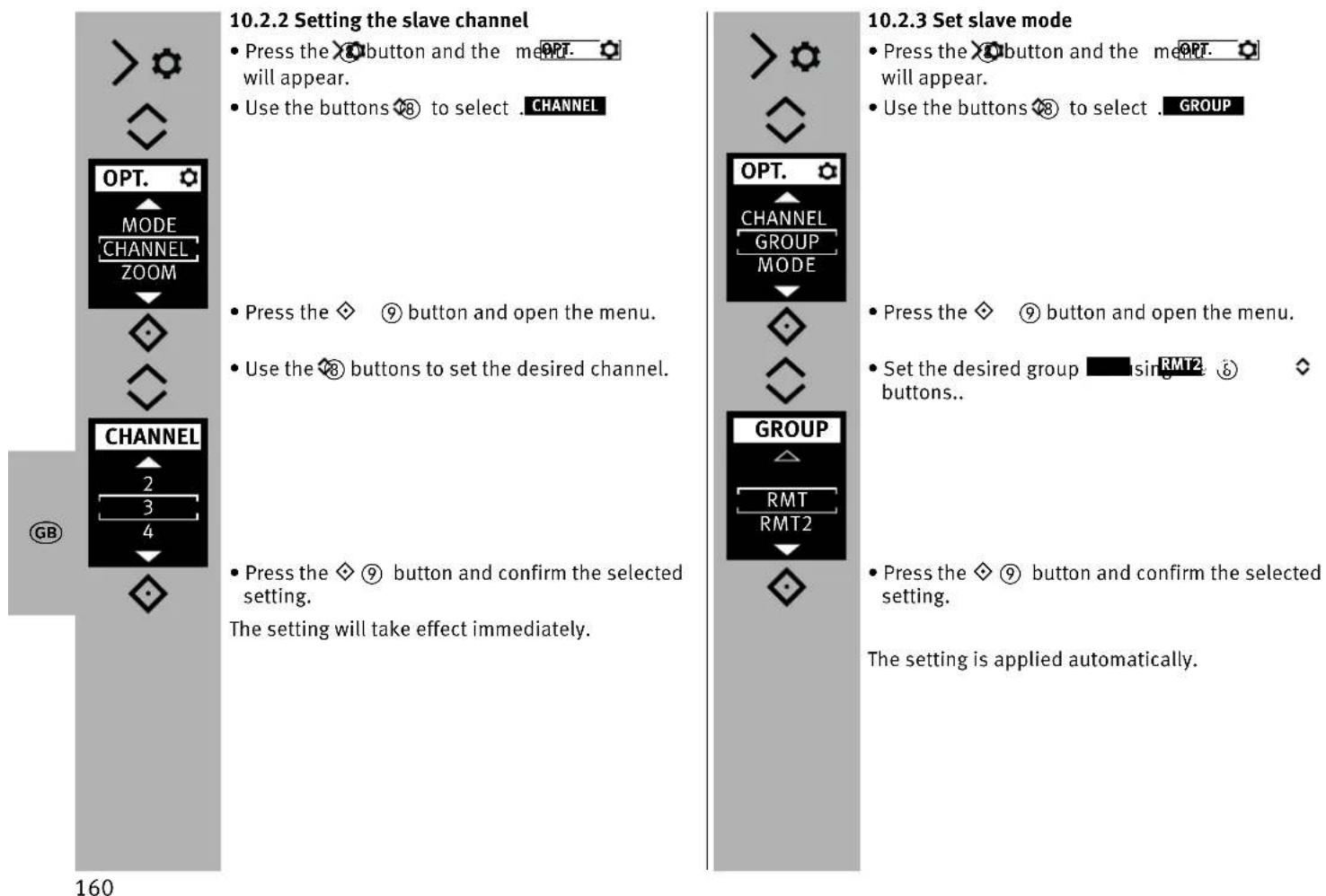
10.2.2 Setting the slave channel 160
10.2.3 Set slave mode ..... 160
10.2.4 Setting partial light output correction ..... 161
10.2.5 Setting partial light output/exposure correction.....161
10.3 SERVO mode 162
10.3.1 Setting SERVO flash mode ..... 162
10.3.2 Pre-flash suppression or synchronisation settings ..... 163
10.3.3 Servo mode partial light output settings ..... 163
10.3.4 Learn function 163
11 OPTION menu....164
11.1 Automatic Zoom Operation (A-ZOOM) 164
11.2 Manual Zoom Operation.... 164
11.3 AF auxiliary light (AF-BEAM) 165
12 Flash techniques .... 166
12.1 Bounce flash 166
12.2 Bounce flash with a reflector card 166
13 Flash synchronisation .... 167
13.1 Automatic flash sync speed control....167
13.2 Normal synchronisation 167
13.3 Slow synchronisation (SLOW) 167
13.4 Second curtain synchronisation (2nd curtain, SLOW2) .... 168
14 Display settings....169
14.1 Brightness....169
14.2 Range display in m or ft (UNIT)....169
15 Care and maintenance....170
15.1 Firmware updates....170
15.2 Conditioning the flash capacitor....170
15.3 Factory settings (RESET) 170
16 Troubleshooting....171
17 Technical data....173
18 Optional accessories....174
Table 1: Guide numbers at maximum light output (P 1/1) ..... 266
Table 2: Flash durations at the individual partial light output levels . 267
Table 3: Maximum guide numbers at HSS/FP-Mode ..... 267
Table 4: Recycling times and number of flashes with different battery types....268
Introduction
Thank you for choosing a Metz product.
We are delighted to welcome you as a customer. You will of course be impatient to start using the flash unit.
However, it is worthwhile reading the operating instructions and learning how to use the unit correctly.
This flash unit is suited for:
- Digital Sony cameras with TTL preflash and ADI metering.
This flash unit is not suited for other brands of cameras.
Take a look at the diagrams at the end of the manual.
Declaration
Tip, note
Attention - Extremely important safety information!
Proper Use
This flash unit is intended solely for taking pictures of motifs in the photographic field. It may be operated only with the accessories described in this instruction manual or the accessories approved by Metz.
The flash unit may not be used for any purpose other than that described above.
1 Safety instructions
The flash unit may in no event be activated in the vicinity of inflammable gases or liquids (petroleum, solvents etc.). RISK OF EXPLOSIONS!
Do not flash directly into eyes from a close distance! Direct flashing into the eyes of persons or animals can cause damage to the retina and severe disruption of the vision – up to and including permanent blindness!
⚠️ Never use a flash unit to photograph car, bus, bicycle, motorbike or train drivers while they are driving. Blinding the driver can lead to an accident!
If the housing has been damaged in such a way that internal components are exposed, the flash unit may no longer be used. Remove the batteries! Do not touch any internal components.
HIGH VOLTAGE!
After repeated flashing, do not touch the diffuser. Risk of burns!
Do not dismantle the flash unit!
HIGH VOLTAGE!
Repairs should only be performed by authorised service personnel.
- The flash unit is exclusively designed and authorised for use in photographic applications.
- Only use the power sources designated and autho-rised in the operating manual!
- Do not open the batteries or short them!
- In no event the batteries be exposed to high temperatures like direct sunlight, fire or similar!
- Never throw flat/dead batteries onto a fire!
- Do not use any toxic batteries or rechargeable batteries!
- Remove the used batteries immediately from the device! Chemicals can escape from used batteries (so-called “leaks”) resulting in damage to the device!
- Batteries may not be recharged!
- Do not expose the flash unit to water drops and splashes!
- Protect your flash unit from heat and high air humidity! Do not keep it in the glove compartment of your car!
- Rapid changes in temperature may lead to condensation. If this occurs, allow time for the unit to become acclimatized!
- When you activate the flash, there should be no opaque material directly in front of or on the reflector cover (flash window). The intense energy emissions can otherwise lead to scorching or spotting of the material and/or the reflector cover.
- After a series of flashes with full power and short intervals, a pause of at least 3 minutes must be observed after each series of 20 flashes!!
- When taking a series of flash shots at full light output and with rapid recycling times, and with zoom positions of 35mm and less, the diffuser heats up, due to the high level of thermal energy.
- This flash unit may be used in combination with a camera-integrated flash only if the flash can be folded out completely.
2 Dedicated flash functions
Dedicated flash functions are flash functions that have been specially adapted to a given camera system. Depending on the type of camera, different flash functions are supported.
- Flash-ready indication in camera viewfinder/camera display
• Automatic flash sync speed control - Preflash TTL and ADI metering
- Manual flash mode
- Manual flash TTL exposure correction
- 1st or 2nd curtain synchronisation (REAR).
• Automatic high speed synchronisation (HSS) for TTL and M
• Automatic motor zoom control
• AF measuring beam control
• Automatic flash range indication - Wireless remote flash mode
- Servo mode
- Wake-up function for the flash unit
- Programmed auto flash mode

It is impossible to describe all camera types and their individual dedicated flash functions within the scope of these instructions.
Therefore, please refer to the flash mode description in your camera's operating instructions to find out which functions are supported and which ones have to be set manually on the camera.
Using lenses not equipped with a CPU (i.e., lenses without auto focus mode), results in certain functional limitations!
3 Preparing the flash unit for use
3.1 Power supply
Suitable batteries/rechargeable batteries
The flash unit can be operated with any of the following batteries:
- 4 nickel-metal-hydride batteries 1.2V, type IEC HR6 (size AA). They have a significantly higher capacity than NiCad batteries and are less harmful to the environment, since they have no cadmium.
- 4 alkaline-manganese dry cell batteries 1.5V, type IEC LR6 (size AA). Maintenance-free power source for moderate power requirements.
- 4 lithium batteries 1.5V, type IEC FR6 (size AA). Maintenance-free high-capacity power source with a low self-discharge rate.


Please only use the power sources given above. If other power sources are used, there is a risk of damaging the flash unit.
If your flash unit is not going to be used for an extended period of time, remove the batteries.
Replacing batteries
The disposable/rechargeable batteries are empty or used up if the recycling time (time from the triggering of a full-power flash, e.g. in the M mode, to the moment the flash-ready indicator lights up again) exceeds 60 seconds. In addition, the battery warning appears on the display.
- Switch off the flash unit. To do this, press the Ⓐ⑦ button until all displays turn off.
- Remove flash unit from the camera, push battery cover downwards and open.
- Insert batteries lengthwise according to the battery symbol indicated.
- Close battery cover and push upwards.
When inserting batteries, ensure that the polarity is correct and matches the symbols in the battery compartment. Inserting the batteries in the wrong direction can destroy the flash unit! Always replace all batteries simultaneously, and make sure that batteries are the same brand and have the same capacity.
Flat or dead batteries should not be disposed of with ordinary household waste. Help protect the environment, and dispose of flat/dead batteries at the appropriate collection points.

3.2 Mounting the flash unit
Mounting the flash unit on the camera
Turn off the camera and flash before mounting or removing.
- Remove the protective cap from the unit base.
- Turn the knurled nut ⑪ towards the flash unit housing as far as it will go. The locking pin in the adapter shoe is now fully retracted into the case.
- Slide the flash unit foot completely into the camera accessory shoe.
- Turn the knurled nut ⑪ towards the camera housing as far as it will go, clamping the flash unit in place. If the camera does not have a locking hole, the spring-loaded locking pin retracts into the adapter case so as not to damage the surface.
Removing the flash unit from the camera
Turn off the camera and flash before mounting or dismounting.
- Turn the knurled nut ⑪ towards the flash unit housing as far as it will go.
- Remove the flash unit from the camera's accessory shoe.

3.3 Switching the flash unit on and off
- Switch on the flash unit with the ⏻⑦ button. The start screen appears.
The flash unit always switches on afterwards with the mode of operation that was used last.
The ⏻ ⑦ button flashes red in stand-by mode. To switch off the flash unit, press the ⏻ ⑦ button until all displays turn off.
If the flash unit will not be used for an extended period of time, we recommend that you switch off the flash unit with the ⏻⑦ button and remove the power source (disposable/rechargeable batteries).
3.4 The selection menu
- Press the ⏻ button and the drop-down menu will appear.
The ⑧ buttons can be used to select the operating mode.
AUTO, chap. 7.1
TTL, chap. 7.2
TTL HSS, chap. 7.4
M, chap. 7.3
M HSS, chap. 7.4
LED, chap. 7.5
REMOTE MASTER, chap. 10.1
REMOTE SLAVE, chap. 10.2
SERVO, chap. 10.3
F1 / F2, chap. 7.6
3.5 The OPTIONS Menu
- Press the ⚫ button and the will appear.

With the ⑧ buttons, the options; can be chosen independently of the operating mode.
ZOOM (reflector setting), chap. 9.1
STANDBY (autom., unit switch-off), chap. 3.7
AF BEAM (AF auxiliary light), chap. 11.3
DISPLAY, chap. 14.1
UNIT (metres / feet), chap. 14.2
RESET, chap. 15.3
MODE ^2) 3), chap. 10.1.2
RATIO ^2) (lighting conditions), chap. 10.1.4
CTRL+ (Remote), chap. 10.1
CHANNEL ^2)3) (Channel), chap. 10.2.2
GROUP ^3) (slave group), chap 10.2.3.
SYNC ^4) , chap. 10.4.2
2) only in MASTER mode
3) only in SLAVE mode
4) only in SERVO mode.
The displayed flash parameters are dependent on the selected flash mode.
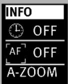
3.6 INFO
The current settings of the flash unit can be displayed during operation.
- Press and hold the ◇ ⑨ button.
The will appear.
What is displayed will depend on the operating mode and the selected options.
3.7 Auto OFF for the flash unit
The flash unit is factory-set to automatically switch to standby mode (Auto OFF) 3 minutes after
- being switched on,
- a flash is fired,
• the shutter release is actuated, - the camera's exposure metering system is switched off...
... switched to stand-by mode, (Auto-OFF) to save energy and to protect the power source from unintentional discharging.
The active automatic unit switch-off is shown in the INFO display.
The flash ready indicator ⑦ and the indicators on the LC display disappear.
The ⏻⑦ button flashes red in stand-by mode.
The most recently used operating setting is retained after automatic shutdown and is immediately restored when the camera is switched on.
The flash unit can be turned on again by pressing the ◇ ⑨ button, or by tapping on the shutter release (wake-up function).
In SLAVE/SERVO mode, the automatic cut-off is not activated.
The flash unit should always be turned off using the main switch ⏻ ⑦ if it is not going to be used for an extended period!
The flash unit switches off completely about 1 hour after its last use.


flowchart
graph TD
    A["OPT."] --> B["ZOOM / STANDBY / AF-BEAM"]
    B --> C["STANDBY"]
    C --> D["OFF / ON"]
    D --> E["OK"]
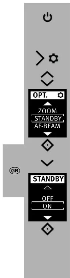
Setting the automatic unit switch-off
- Switch on the flash unit with the ⏻⑦ button. The start screen appears. The flash unit always switches on afterwards with the mode of operation that was used last.
- Press the ⚙ button and the me OPT. will appear.
-
Use the ⑧ buttons to select the menu option STANDBY.
-
Press the ◇ ⑨ button and open the menu.
- Use the ⚙8 button to select the menu option ON
- Press the ◇ ⑨ button and confirm the selected setting.
The ⏻⑦ button flashes red in stand-by mode.
4 OLED displays on the flash unit
4.1 Flash readiness indication
When the flash capacitor on the flash unit is charged, the ⏻⑦ button lights up in green, thus indicating that the flash unit is ready.
This means that flash light can be used for the next shot. Flash readiness is also transmitted to the camera and indicated accordingly in the camera's viewfinder.
If a photograph is taken before flash readiness appears, then the flash unit will not be triggered. If the camera has already switched to flash sync speed, the shot may have the wrong exposure (see 13.1).
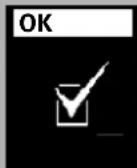
4.2 Correct exposure indication
With proper exposure, the OK symbol will light up on the display for about 3 seconds if the recording in flash modes. pTL flash TTL, ADI flash metering and automatic mode (sAUTO.1) were properly exposed!!
If there is no exposure control indication after the shot, then the photograph was underexposed. In that case, you must:
- set the next smaller f-stop (e.g. use f-stop 8 instead of 11), or
- reduce the distance to the subject or to the reflection surface (e.g. for indirect flashes), or
- set a higher ISO value on the camera.
Note the maximum flash range indicated on the display of the flash unit (see 5.2).
5 Information in Display
The cameras transmit the settings for ISO, lens focal length (mm) and aperture to the flash unit. It calculates the maximum flash range from the settings and their guide number.
Flash mode and range are shown on the flash unit's display.
If the flash unit is operated without receiving data from the camera, then the values set on the flash unit will be shown.
5.1 Display of the flash mode
The current flash mode is shown in the display. Depending on the type of camera, different displays are available for the selected TTL flash mode (e.g. and) and the mHSS HSS flash mode (seM 7.4).
5.2 Range display
When using cameras and a lens with CPU, the range is indicated in the display.
For this a data exchange must have occurred between the camera and flash unit, for example by tapping the shutter release. The range can be displayed either in metres (m) or feet (ft) - see 14.2).

The flash range is not displayed when . . .
- when the reflector head is tilted out of its normal position (upwards or sideways).
- if the flash unit is working in REMOTE MASTER, REMOTE SLAVE, SERVO or AUTO mode.
5.2.1 Range display in TTL- and TTL HSS flash modes
In the TTL flash modes and ; TTLTTL HSS see 7.2) the value for the maximum range of the flash unit is displayed.
The value indicated relates to subjects with a reflection factor of 25%, which applies to most photographic situations.
Strong deviations from this reflection factor, as in the case of highly reflective or poorly reflective subjects, may affect the flash range of the flash unit.
The subject should be in the range of 40% to 70% of the maximum range. This will give the electronics sufficient scope for compensation.
To avoid overexposure, at least 10% of the maximum range should be maintained as the minimum distance from the subject of the photo.
Adjustment to the photographic situation at hand can be achieved by, for example, changing the aperture of the setting on the lens.
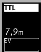
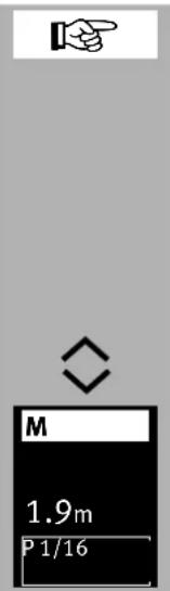
5.2.2 Range display in manual flash mode
In manual flash mode, the distance that must be maintained from the subject for correct flash exposure is indicated. Adjustment to the photographic situation at hand can be achieved by, for example, changing the aperture setting on the lens or selecting a manual partial light output level (see 7.3).
5.2.3 Exceeding the display range
Flash ranges of up to 99 m or 99 ft can be shown in the display.
This display range can be exceeded in the case of high ISO values and large aperture openings.
An arrow or triangle after the distance value indicates that the display range has been exceeded.
6 Displays in the camera viewfinder
Examples for the camera viewfinder display:
Flash symbol is illuminated:
The flash unit is ready for use (by some cameras).
Flash symbol flashes slowly:
Switch on the flash unit.
Incorrect exposure guidelines:
• overexposure: do not use the flash!
- underexposure: switch the flash on or use a tripod and a longer exposure time.
Reasons for incorrect exposure can lay in the various exposure and automatic programmes.
For information applicable to the displays in the viewfinder of your camera model, refer to the camera's operating instructions.
7 Flash modes
Depending on the camera model, the following flash modes are available:
• Automatic flash mode ( ), AUTOp. 7.1
- Preflash TTL( ), dTMap. 7.2
- Manual flash mode ( ), cMap.7.3
• Automatic high-speed synchronisation (HSS), chap. 7.4
• rMASTER Settings , chap. 10.1
- flSLAVE mode, chap. 10.2
• SERVO mode, chap. 10.4.
A data transfer between flash unit and camera is necessary before setting flash mode TTL HSS and e.gMby a HSS ting the shutter release.
7.1 AUTO Flash Mode
With the AUTO flash mode, the flash unit can be used easily for flash photography. It is not necessary to select particular settings on the flash unit.
The AUTO flash mode is a simplified flash mode for digital cameras without settings choices and/or the camera mode "P mode" and the fully automatic mode.
7.2 Preflash TTL and ADI metering
Preflash TTL and ADI metering are digital TTL flash operating modes and refined versions of the TTL flash operation found in analogue cameras. When taking a shot, an almost imperceptible measurement preflash is triggered by the camera prior to the actual exposure process. The reflected light of the measurement preflash is evaluated by the camera. Depending on the result of the evaluation, the subsequent flash exposure is adapted by the camera to suit the given shot situation (see camera operating instructions for further details). In the case of ADI metering, additional distance data from the lens is incorporated into the flash exposure process. The selection and/or setting of the preflash TTL and ADI metering operating modes are carried out on the camera (see camera operating instructions).
The flash unit must be set to the or TTL AUTO flash operating mode.

flowchart
graph TD
    A["MODE"] --> B["AUTO"]
    B --> C["TTL"]
    C --> D["TTL HSS"]
    D --> E["7.9m EV"]
Setting the mode of operation
- Switch on the flash unit with the ⏻ ⑦ button.
The start screen appears. Thereafter, the flash unit always switches on with the mode of operation that was used last. - Press the Ⓤ button and the drop-down menu will appear.
- Use the ⏻ buttons to select the d, TTL ting mode.
- Press the ◇ ⑨ button and confirm the selected operating mode.
- Set a suitable mode of operation on the camera, e.g. P, S, A etc.
- Tap the shutter release to transfer data between the flash unit and the camera.
7.3 Manual flash mode
In the manual flash mode M, the flash unit emits the full uncontrolled amount of light if no partial light output has been selected. The specific photographic situation can be taken into account by adjusting the aperture setting or by selecting a suitable manual partial light setting.

The setting area ranges from P 1/1 to P1/256 in mode and P1/1 - P1/32 in nHDSSM The display shows the distance at which the subject is correctly lit (see 5.2).
Setting the mode of operation
- Switch on the flash unit with the ⏻⑦ button.
The start screen appears.
Thereafter, the flash unit always switches on with the mode of operation that was used last.
- Press the ⏻ button and the drop-down menu will appear.
- Use the Ⓤ8 buttons to select the operating mode.
- Press the ◇ ⑨ button and confirm the selected operating mode.
- Tap the shutter release to transfer data between the flash unit and the camera.

Various cameras support manual flash mode M only in the camera's M mode (manual). In other camera models, an error message appears in the display and the release is locked.
Manual partial light output levels
Partial light output can be set in manual flash mode.
Setting procedure
- Use the ⏻ buttons to set the desired partial light output (P). The distance information is adjusted according to how the partial light output is set.
The setting is immediately effective and automatically saved.
The distance display is adjusted to the partial light output automatically (see 5.2).
7.4 Automatic high-speed synchronisation (HSS)
Various cameras support automatic high-speed synchronisation (see the camera's operating instructions). This flash mode makes it possible to use a flash unit even with shutter speeds that are faster than the flash sync speed.
Interesting results may be achieved in this mode when, for example, a wide open aperture (e.g., f/2.0) is used to limit the depth of field in portrait shots taken in very bright ambient light. The flash unit supports high-speed synchronisation in TTL and flash mode.
For physical reasons, however, high-speed synchronisation significantly reduces the number and the maximum flash range.
Be sure to note, therefore, the flash range on the display of the flash unit.
High-speed synchronisation is activated automatically if a shutter speed faster than the flash sync speed is set on the camera, whether manually or automatically by the exposure program.
Note that in the case of high speed synchronisation the guide number of the flash unit also depends on the shutter speed.
The faster the shutter speed, the lower the guide number!
High-speed synchronisation is activated automatically if a shutter speed faster than the flash sync speed is set on the camera, whether manually or automatically by the exposure program.
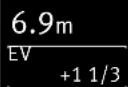
| Setting the mode of operation • Switch on the flash unit with the ⑦ button. The start screen appears. Thereafter, the flash unit always switches on with the mode of operation that was used last. • Tap the shutter release to transfer data between the flash unit and the camera. • Press the ⑧ button and the drop-down menu will appear. • Use the ⑨ buttons to select the TTL HSS MHSS operating mode.. MODE TTL TTL HSS M ⑧ TTL HSS 6.9m EV +1 1/3 Second curtain synchronisation (REAR) is automatically deactivated when the flash unit is set to high-speed synchronisation HSS! | 7.5 LED Video Light With the LED and video light modes, you can examine recordings of moving pictures at close range. Setting the mode of operation • Switch on the flash unit with the ⑦ button. The start screen appears. Thereafter, the flash unit always switches on with the mode of operation that was used last. • Press the ⑧ button and the drop-down menu will appear. • Use the ⑨ buttons to select the LED ting mode. • Press the ⑨ button and confirm the selected operating mode. • Use the ⑧ buttons to select the desired brightness. The setting will take effect immediately. | |

flowchart
graph TD
    A["≡"] --> B["MODE"]
    B --> C["SERVO"]
    C --> D["F1"]
    C --> E["F2"]
    D --> F["↓"]
    E --> G["↓"]
    F --> H["F1"]
    H --> I["LOAD"]
    I --> J["SAVE"]
    J --> K["↓"]
7.6 Favorite programme
In flash photography there are always recurring standard situations (e.g. birthday celebrations at home, etc.). The ecablitz permits the settings for such standard situations to be stored as a favorite programme so that the selected flash parameters can be instantly reset.
The flash unit has 2 memory locations for saving the settings made on the flash unit.
Procedure for saving a favourite programme
- Set the flash unit parameters as desired. Set the desired operating mode. Set the options for the desired operating mode.
- Press the Ⓤ button and the drop-down menu will appear.
-
Use the Ⓤ8 buttons to select the dthe storage locations.
-
Press the ◇ ⑨ button to confirm the selected storage location.
-
Use the buttons ⏻ to select. SAVE
-
Press the ◇ ⑨ button to confirm the selected storage location.
• The o.k sign appears on the display. - Press the ◇ ⑨ button to confirm the selected storage location.
• The o.k sign appears on the display.

flowchart
graph TD
    A["≡"] --> B["MODE"]
    B --> C["SERVO"]
    C --> D["F1"]
    D --> E["F2"]
    E --> F["◇"]
    F --> G["◇"]
    G --> H["F1"]
    H --> I["LOAD"]
    I --> J["SAVE"]
    J --> K["◇"]
Procedure for loading a favourite programme
- Press the ⏻ button and the drop-down menu will appear.
-
Use the Ⓤ8 buttons to select the dne storage locations.
-
Press the ◇ ⑨ button to confirm the selected storage location.
-
Use the buttons ⑧ to select . LOAD
-
Use the ◇ ⑨ button to confirm loading of the favourite mode.
- Use the ◇ ⑨ button to confirm loading of the favourite mode.
• The o.k sign appears on the display.
8 Manual flash exposure correction
The auto flash exposure mode of most cameras is adjusted to a reflection factor of 25% (the average reflection factor of flash subjects).
A dark background that absorbs much of the light or a highly reflective bright background (backlit shots, for example) may result in, respectively, underexposure or overexposure of the subject.
To offset these effects, the flash exposure can be adjusted manually for the shot with a correction value. The extent of the correction depends on the contrast between the subject and background! In TTL flash modes, manual flash exposure correction factors of from -3 EV (f-stops) to +3 EV (f-stops) can be adjusted on the flash unit in one-third increments.
Tip:
Dark subject against light background: positive correction factor.
Light subject against dark background: negative correction factor.
Exposure correction by means of alteration of the lens aperture setting is impossible, since the camera's automatic exposure program regards the altered aperture setting as the normal working aperture setting.
When setting the correction factor, the distance shown in the display can change and be adjusted to the correction factor (depending on the camera model)!


Setting procedure
- Press the ⏻ buttons repeatedly and set an exposure value (EV).
The setting will take effect immediately.
Manual flash exposure correction is only possible in TTL flash mode if the camera supports this function (consult the camera's operating instructions)!
If the camera does not support this function, the adjusted correction will have no effect.
For some camera models, the manual flash exposure corrections must be adjusted on the camera. If this is the case, no correction value will appear on the flash unit display.
After the shot, remember to cancel the manual flash exposure correction in the camera!
Strongly reflecting objects in the motif can have a negative impact on the camera's automatic exposure. The photograph will be underexposed. Remove reflecting objects or set a positive correction value.
9 Special functions
Depending on the camera model or camera group, various special functions are available.
For this purpose, data exchange must first occur between the flash unit and camera to access and set the special functions, for example by tapping the shutter release.
The setting must occur immediately after accessing the special functions since otherwise the flash unit automatically switches back to normal flash operation after a few seconds!
The motor zoom reflector of the flash unit can illuminate lens angles from 24 mm (35 mm format).
Thanks to the use of the integrated wide-angle diffuser ⑨, the illumination widens to 12 mm.
9.1.1 Auto zoom
The zoom position of the reflector is automatically adjusted to the lens focal length when the flash unit is used with a camera that transmits the data related to the lens focal length.
Automatic adjustment occurs for lens focal lengths from 24 mm.
The automatic adjustment will not be activated if the reflector is swivelled, if the wide-angle diffuser ② is pulled out, or a Mecabounce (accessory) is mounted.
If so desired, the position of the reflector can be manually adjusted in order to achieve particular lighting effects (such as spot effect etc.).
flowchart
graph TD
    A["Start"] --> B{Opt.}
    B --> C["ZOOM STANDBY"]
    C --> D{Zoom Level}
    D --> E["ZOOM"]
    E --> F["28mm"]
    E --> G["35mm"]
    E --> H["50mm"]
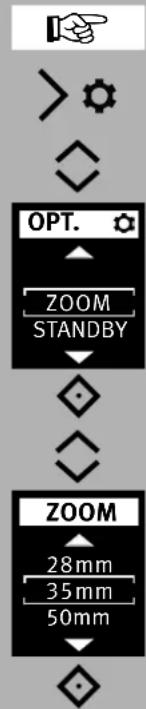
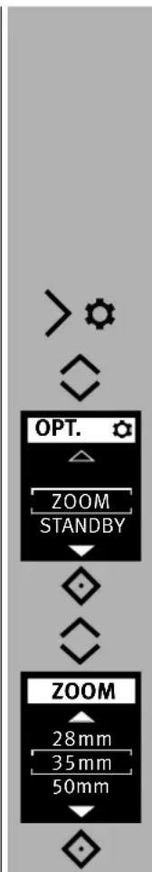
9.1.2 Manual zoom mode
The zoom position of the reflector must be adjusted manually to the lens focal length when used with a camera that doesn't transmit the data related to the lens focal length.
In this case auto-zoom mode is not possible!
Setting procedure
- Press the ⚫ button and the menu. will appear.
-
Use the buttons ⑧ to select . ZOOM
-
Press the ◇ ⑨ button and open the menu.
- Use the Ⓧ buttons to select a zoom level.
- Press the ◇ ⑨ button and confirm the selected setting.
The setting will take effect immediately.
The following zoom positions are possible for the reflector: 24-28-35-50-70-85-105 mm (35 mm format).
Tip:
If you do not necessarily need the full guide number and maximum flash range of the flash unit, you can leave the zoom reflector at the position for the shortest focal length of the zoom lens.
This will provide full light coverage of the picture and eliminate the need to continually adjust it to the focal length of the lens.
Example:
You use a zoom lens with a focal length range of 35 mm to 105 mm. In this case, you set the position of the reflector of the flash unit to 35 mm.

flowchart
graph TD
    A["> gear"] --> B["OPT."]
    B --> C["ZOOM AF-BEAM"]
    C --> D["◇"]
    D --> E["ZOOM"]
    E --> F["A-ZOOM 24 mm"]
    F --> G["◇"]
Resetting to auto-zoom
- Touch the shutter release to begin a data transfer between the flash unit and the camera.
- Press the ⏻ button and the menu. will appear.
-
Use the buttons ⑧ to select . ZOOM
-
Press the ◇ ⑨ button and open the menu.
- Use the buttons Ⓧ to select . A-Zoom
- Press the ◇ ⑨ button and confirm the selected setting.


9.2 Wide-angle diffuser
With the wide angle diffuser ②, focal lengths of 12mm or more can be illuminated (35 mm format). Pull the wide-angle diffuser ② out from the reflector as far as it will go, and then release it.
The wide-angle diffuser ② automatically folds downwards. The reflector automatically moves to the required position.
The automatic adjustment of the motor-zoom reflector ② is not activated if the wide-angle diffuser is in use.
To insert the wide-angle diffuser ②, turn it upwards 90° and push it all the way in.
9.3 mecabounce Diffuser MBM-04
If the mecabounce (optional accessories, see 18) is fitted to the reflector of the flash unit, the reflector is automatically guided to the position required. The distance data and zoom factor are corrected to 16 mm.
The automatic adjustment of the motor-zoom reflector is not activated if the mecabounce is in use.
The simultaneous use of the wide-angle diffuser and the mecabounce is not possible.

10 Cordless flash mode
The flash unit supports the wireless Sony remote system "CTRL+".
The remote system consists of a master flash unit on the camera and one or more slave flash units. The slave flash unit(s) are controlled via wireless technology by the reflector of the master flash unit. There are four independent remote channels to use so that multiple remote systems in the same room do not interfere with one another. Master and Slave flash units belonging to the same remote system must be set to the same remote channel.
The slave flash units must be able to receive the light from the master flash unit with the integrated sensor for remote mode ⑫.
In remote flash mode, the maximum flash range is not indicated on the flash unit's display panel.
10.1 Remote master mode settings
Remote master mode on the camera is set. For this, mount the M400 in the hot shoes of the camera and set wireless flash mode WL on the camera.
After that, the master mode CTRL+ is automatically activated on the M400.
Remote master mode can only be used and can only be set if the camera actually supports that mode.

If the camera does not support remote master mode, it cannot be set and is automatically deleted. When operating cameras not supporting remote master mode, the remote slave mode is automatically activated for the M400. The remote channel between camera and flash unit is automatically adjusted.
In remote master mode CTRL+, two separate slave groups RMT and RMTR2 can be triggered and wirelessly controlled in the light output by the master CTRL. The fully automatic wireless TTL flash mode and the manual flash mode M with 25 unregulated manual partial light output levels are available as operating modes.
The type of flash mode for the master and slave flash units must be selected or set on each flash unit individually.
In wireless TTL flash mode as well as in wireless manual flash mode M, the master CTRL and the slave groups RMT and RMT2 can be used with or without ration control (RATIO OFF).
flowchart
graph TD
    A["> サーフェ"] --> B["OPT. MODE CHANNEL ZOOM"]
    B --> C["◇"]
    C --> D["◇"]
    D --> E["CHANNEL 2 3 4 ◇"]
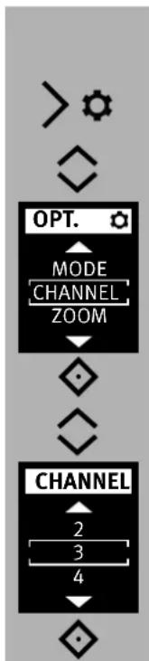
10.1.1 Setting the remote channel
- On the camera, set the wireless flash mode WL.
- Press the ⚙ button and the me OPT. will appear.
- Use the buttons ⑧ to select . CHANNEL
- Press the ◇ ⑨ button and open the menu.
- Use the Ⓤ8 buttons to set the desired channel.
- Press the ◇ ⑨ button and confirm the selected setting.
In the example, the remote channel CHANNEL 3 was selected.
The setting will take effect immediately.

The master CTRL and the slave groups RMT and RMT2 must all be set to the same remote channel!
The channel setting, in the example CHANNEL 3 (CH. 3), can be checked by pressing the information key ◇ ⑨.

flowchart
graph TD
    A["> gear"] --> B["OPT."]
    B --> C["RATIO"]
    C --> D["MODE"]
    D --> E["CHANNEL"]
    E --> F["◇"]
    F --> G["指向"]
    G --> H["GB"]
10.1.2 Setting the flash mode type of the master
The flash mode type for the master CTRL is set as follows:
- Press the ⚙ button and the me QPT. will appear.
- Use the buttons ◎8 to select . MODE
- Press the ◇ ⑨ button and confirm the selected setting.
The type of flash mode for the slave flash units, must be selected or set on each salve flash unit individually.

flowchart
graph TD
    A["MODE"] --> B["TTL"]
    B --> C["M"]
    C --> D["•"]
    D --> E["CTRL+"]
    E --> F["TTL"]
    F --> G["RATIO OFF"]
    G --> H["EV"]
    H --> I["•"]
    I --> J["CTRL+"]
    J --> K["TTL"]
    K --> L["RATIO OFF"]
    L --> M["EV"]
    M --> N["-1 2/3"]
10.1.2.1 Setting the flash unit type Remote TTL
- Use the Ⓧ keys to select the mode . TTL
- Press the ◇ ⑨ button and confirm the selected setting.
The remote flash mode has been set. In the example, ratio control is deactivated (RATIO OFF).
If so desired, ratio control RATIO can be activated. To do so, see Section 10.1.3 Ratio
If needed, manual flash exposure correction (EV) ranging from -3 to +3 f-stops can be set in steps of 3 in TTL flash mode using the Ⓧ keys. The setting is effective immediately and automatically saved.
In the example, a manual correction value of -1 2/3 EV is displayed..
flowchart
graph TD
    A["MODE"] --> B["TTL"]
    B --> C["M"]
    C --> D["CTRL+"]
    D --> E["M"]
    E --> F["CTRL 1"]
    E --> G["RMT 1"]
    E --> H["RMT2 1"]
    H --> I["P 1/1"]
    J["CTRL+"] --> K["M"]
    K --> L["CTRL 1"]
    K --> M["RMT 1"]
    K --> N["RMT2 1"]
    N --> O["P 1/4"]
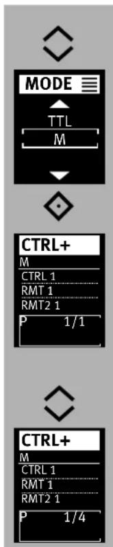
10.1.2.2 Setting the flash mode Remote M
- Use the 🔒 keys to select the mode . M
- Press the °i button and confirm the selected setting.
The remote flash mode has been set. In the example, ratio is activated. If so desired, ratio can be deactivated.
To do so, see Section on ratio control 10.1.3
If needed, manual partial light output P ranging from P 1/1 (max.) and P 1/256 (min.) can be set in steps of 3 in manual flash mode using the ⚡h keys.
The setting is effective immediately and automatically saved.
In the example, a manual partial light output level of P 1/4 is displayed.

flowchart
graph TD
    A["> gear"] --> B["✓"]
    B --> C["OPT. ⚙️"]
    C --> D["RATIO MODE"]
    D --> E["↓"]
    E --> F["RATIO"]
    F --> G["✓"]
    G --> H["OFF CTRL"]
    H --> I["↓"]
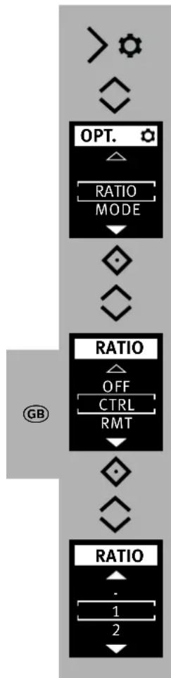
10.1.3 RATIO
If so desired, the RATIO can be set. This will assign a different weight to the master CTRL and the slave groups RMT and RMT2 for lighting purposes.
Activate / deactivate ratio
- Press the ⚙ button and the menu. will appear.
- Use the buttons ⑧ to select . RATIO
- Press the ◇ ⑨ button and confirm the selected setting.
In the OFF position, the ratio is deactivated.
GB
flowchart
graph TD
    A["> サーフ"] --> B["OPT."]
    B --> C["RATIO MODE"]
    C --> D{◇}
    D --> E{◇}
    E --> F["RATIO"]
    F --> G{OFF CTRL RMT}
    G --> H{◇}
    H --> I{◇}
    I --> J["RATIO"]
    J --> K["1 2"]
Activating ratio
- Press the ➕ button and the menu will appear.
- Use the buttons ⑧ to select . RATIO
- Press the ◇ ⑨ button and confirm the selected setting.
- Using the ⑧ keys, select master o CTRL ve group RMT RM have group .
- Press the ◇ ⑨ button and confirm the selected setting.
- Use the ⬇ keys to select the exposure share. When doing so, the settings - / 1 / 2 / 4 / 8 /16 are possible for the exposure share.
In the setting " – ", the corresponding device will not participate in the flash exposure of the photograph.
In the example, the exposure share 1 was selected for the previously selected master CTRL.
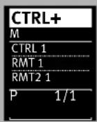
In the following are the settings for the slave groups RMT and RMT2 as well as for the master CTRL after this example.
In the adjacent example, the exposure share for the master CTRL and the two slave groups RMT and RMT2 was set to 1. Therefore, all devices with the same weighting take part in the flash exposure.
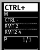
In this example, the master CTRL does not take part in the flash exposure.
The slave group RMT takes part in the flash exposure with 2 of a total of 6 shares (2 + 4 = 6).
The slave group RMT2 takes part in the flash exposure with 4 of a total of 6 shares.
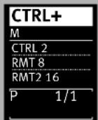
In this example, the master CTRL takes part in the flash exposure with 2 of a total of 26 shares (2 + 8 + 16 = 26).
The slave group RMT takes part in the flash exposure with 8 of a total of 26 shares.
The slave group RMT2 takes part in the flash exposure with 16 of a total of 26 shares.
10.2 Remote slave flash mode
The flash unit supports the wireless remote system in slave flash mode and is compatible with the Sony system.
At the same time, one or more slave flash units can be remotely controlled from one master flash unit on the camera (e.g. mecablitz M400).
A slave flash unit can be assigned to two of three possible slave groups (RMT, RMT2). The master flash unit can control all of these slave groups simultaneously and at the same time take the settings for each slave group into account.
So that multiple remote systems in the same room do not interfere with one another, there are four independent remote channels available (CH 1, 2, 3 or 4).
Master and slave flash units belonging to the same remote system must be set to the same remote channel.
The slave flash units must be able to receive the light from the master flash unit with the integrated sensor ⑫ for the remote mode.
Depending on the camera model, the camera's internal flash unit can also function as master flash unit.

In slave mode, there is no indication of reach and no automatic adjustment of the zoom position.

flowchart
graph TD
    A["≡"] --> B["MODE"]
    B --> C["MASTER"]
    C --> D["SLAVE"]
    D --> E["SERVO"]
    E --> F["SLAVE"]
    F --> G["RMT"]
    G --> H["CH. 3"]
    H --> I["EV"]
10.2.1 Remote slave flash mode settings
- Switch on the flash unit with the ⏻⑦ button. The start screen appears. Thereafter, the flash unit always switches on with the mode of operation that was used last.
- Press the ⏻ button and the drop-down menu will appear.
- Use the 78 buttons to select the operating rating mode.
- Press the ◇ ⑨ button and confirm the selected operating mode.
Remote slave mode is set.
In addition, the selected slave group (e.g. RMT) and the remote channel (e.g. CH 3) are displayed.
flowchart
graph TD
    A["10.2.2 Setting the slave channel"] --> B["OPT. MODE CHANNEL ZOOM"]
    B --> C["CHANNEL 2 3 4"]
    C --> D["160"]
    E["10.2.3 Set slave mode"] --> F["OPT. CHANNEL GROUP MODE"]
    F --> G["GROUP RMT RMT2"]
    G --> H["Press the ◇ ⑨ button and open the menu. Use the ◊8 buttons to set the desired channel. Press the ◇ ⑨ button and confirm the selected setting. The setting will take effect immediately."]
    I["The setting is applied automatically."] --> J["Press the ◇ ⑨ button and open the menu. Set the desired group using RMT2 buttons.."]
flowchart
graph TD
    A["> gear"] --> B["◇"]
    B --> C["OPT."]
    C --> D["GROUP\nMODE\nZOOM"]
    D --> E["◇"]
    E --> F["◇"]
    F --> G["MODE"]
    G --> H["TTL\nM"]
    H --> I["◇"]
    I --> J["SLAVE\nRMT2\nCH. 3\nEV"]
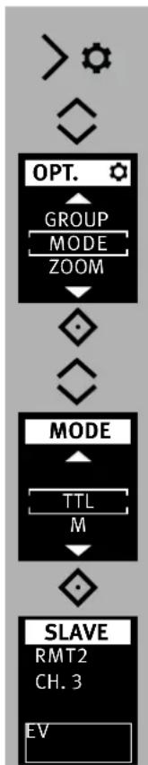
10.2.4 Setting partial light output correction
- Press the ⚫ button and the menu. will appear.
-
Use the buttons ⑧ to select . MODE
-
Press the ◇ ⑨ button and confirm the selected operating mode.
- Use the ⑧ buttons to choose either the TTL or the operating mode.
- Press the ◇ ⑨ button and confirm the selected setting.
The setting will take effect immediately.
10.2.5 Setting partial light output/exposure correction
- Press ⑱ buttons repeatedly and set the exposure compensation (EV) or a partial light output (P). The partial light output/exposure compensation value is applied.
Once the slave flash units have achieved flash-readiness, the AF measurement flash flashes.

10.3 SERVO mode
SERVO mode is a simple slave mode without or with complete pre-flash suppression in which the slave flash unit always triggers a flash as soon as the camera flash unit receives a light pulse.
In SERVO mode, only manual flash mode is possible. Manual flash mode is automatically activated after switching to SERVO mode.
When the flash of the camera AF illuminator emits the auto focus servo operation is not possible. Disable the AF measuring beam on the camera
Use a different AF mode of the camera or switch to manual focusing.

flowchart
graph TD
    A["MODE"] --> B["AUTO"]
    B --> C["TTL"]
    C --> D{ }
    D --> E["MODE"]
    E --> F["SLAVE"]
    F --> G["SERVO"]
    G --> H["F1"]
    H --> I{ }
    I --> J["SERVO"]
    J --> K["P 1/1"]
10.3.1 Setting SERVO flash mode
- Press the ⏻ button and the drop-down menu will appear.
- Use the ⑧ buttons to select the d SERVO rating mode.
- Press the ◇ ⑨ button and confirm the selected operating mode.
The mode of operation is adopted. If desired, partial light output can be set, see 10.3.3.
flowchart
graph TD
    A["> √"] --> B["OPT."]
    B --> C["SYNC ZOOM"]
    C --> D{ }
    D --> E{ }
    E --> F["SYNC"]
    F --> G["LEARN"]
    G --> H{ }
    H --> I["SERVO"]
    I --> J["P 1/1"]
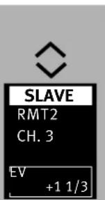
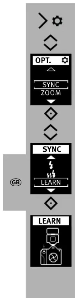
10.3.2 Pre-flash suppression or synchronisation settings
- Press the ⚙ button and the me OPT. will appear.
-
Use the buttons ⑧ to select . SYNC
-
Press the ◇ ⑨ button and open the menu.
- Use the ⑧ buttons to select the desired synchronisation mode.
Synchronisation without pre-flash
Synchronisation with pre-flash
- Press the ◇ ⑨ button and confirm the selected setting.
The mode of operation is adopted.
If the synchronisation set here does not work properly, then proceed as described in 10.3.4.

10.3.3 Servo mode partial light output settings
- Use the ⏻ buttons to set the desired partial light output (P).
The partial light output is adopted.
Once the slave flash units have achieved flash-readiness, the AF measurement flash flashes.
Remote channels cannot be set in SERVO mode. The camera flash unit may not work in the remote mode.
10.3.4 Learn function
The “Learn function” enables individual automatic adjustment of the slave flash unit to the flash technology of the camera’s flash unit.
In the process, one or more pre-flashes, e.g. to reduce the "red-eye effect" of the camera flash unit can be taken into account.
The slave flash unit is then fired to coincide with the main flash that illuminates the actual picture.
If the camera's own flash device provides for automatic focussing AF measuring flashes, then due to the system characteristics no learn operation is possible.
If possible, use another camera mode or change to manual focussing.
flowchart
graph TD
    A["> √"] --> B["OPT."]
    B --> C["SYNC ZOOM"]
    C --> D{ }
    D --> E{ }
    E --> F["SYNC"]
    F --> G["LEARN"]
    G --> H{ }
    H --> I["LEARN"]
Setting procedure for the learn function
The AF pre-flash function of the camera must be switched off.
- Press the ⚫ button and the will appear.

- Use the buttons Ⓧ to select

- Press the ◊
⑨ button and open the menu.
- Use the buttons ⑧ to select

- Press the ◇ ⑨ button and confirm the selected setting.
- "Learn Mode" is ready to learn.
- Press the release button on the camera so that the camera's own flash unit is activated.
If the SERVO flash unit has received a light pulse, then "LEARN OK" appears in the display as confirmation.
The macablitz has learned the flash of the camera flash unit.
flowchart
graph TD
    A["> サーフェ"] --> B["OPT."]
    B --> C["ZOOM STANDBY"]
    C --> D["◇"]
    D --> E["ZOOM"]
    E --> F["28mm"]
    E --> G["35mm"]
    E --> H["50mm"]
    H --> I["◇"]
11 OPTION menu
11.1 Automatic Zoom Operation (A-ZOOM)
With A-zoom operation, the zoom-head position of the reflector is adjusted to the focal length of the camera.
11.2 Manual Zoom Operation
With manual A-zoom operation, the zoom-head position of the reflector must be manually adjusted to the focal length of the camera.
Setting procedure
- Press the ⚫ button and the menu. will appear.
- Use the buttons ⑧ to select . ZOOM
- Press the ◇ ⑨ button and open the menu.
- Use the ⑧ buttons to set the desired zoom level, e.g. 35mm
- Press the ◇ ⑨ button and confirm the selected setting.
The setting is adopted immediately.
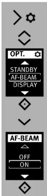
11.3 AF auxiliary light (AF-BEAM)
If the AF metering system of a digital AF reflex camera is unable to focus due to insufficient ambient lighting, the camera activates the AF auxiliary light ⑭ built into the flash unit.
With the "AF-BEAM" function, the AF auxiliary light can be switched on or off.
Parallax error between the lens and AF auxiliary light ⑭ limits the close-up range with the AF auxiliary light to approximately 0.7 m to 1 m.
If the automatic AF auxiliary light ⑭ is to be activated by the camera, the "Single-AF (S-AF)" autofocus mode must be set on the camera and the flash unit must indicate flash readiness.
Some camera models support only the camera's internal AF auxiliary light. In this case, the automatic AF auxiliary light of the flash unit is not activated (as in the case of compact cameras; see the camera's operating instructions).
Low-speed zoom lenses can significantly curtail the range of the AF auxiliary light!
flowchart
graph TD
    A["> ショウ"] --> B["◇"]
    B --> C["OPT."]
    C --> D["STANDBY"]
    D --> E["AF-BEAM DISPLAY"]
    E --> F["◇"]
    F --> G["✓"]
    G --> H["AF-BEAM"]
    H --> I["OFF ON"]
    I --> J["◇"]
Setting procedure
- Press the ⚙ button and the me OPT. will appear.
- Use the buttons ⑧ to select . AF-BEAM
- Press the ◇ ⑨ button and open the menu.
- Use the buttons ⑧ to select ON OFF.
- Press the ◇ ⑨ button and confirm the selected setting.
The setting is adopted immediately.
12 Flash techniques
12.1 Bounce flash
Bounce flash illuminates the subject more softly and reduces dense shadows. It also reduces the drop in light from foreground to background that occurs for physical reasons.
The reflector of the flash unit can be swivelled horizontally and tilted vertically for bounce flash.
To avoid colour cast in your shots, the reflective surface should be colour-neutral or white.
When tilting the reflector vertically, make sure that it is turned through an angle that is wide enough to prevent direct light from falling on the subject. For this reason the reflector should be tilted at least as far as the 60^ lock-in position.
When the reflector head is tilted, the reflector is moved to a position of 70 mm in order to prevent the subject from being additionally illuminated by dispersed light.
When the reflector head is given, there is no indication of reach and no automatic adjustment of the reflector position.
12.2 Bounce flash with a reflector card
The use of bounce flash with the integrated reflector card ① can bring out highlights in the eyes of human subjects:
- Tilt the reflector head upwards by 90^ .
- Pull the reflector card ① together with the wide-angle diffuser ② from above out of the reflector head and forwards.
- Hold the reflector card ① and push the wide-angle diffuser ② back into the reflector head.
13 Flash synchronisation
13.1 Automatic flash sync speed control
Depending on the camera model and camera mode, the shutter speed is switched to flash sync speed when flash readiness is reached (see the camera's operating instructions).
Shutter speeds cannot be set faster than the flash sync speed, or they are switched automatically to the flash sync speed.
Various cameras have a sync speed range, for example from 1/60 sec to 1/250 sec (see the camera's operating instructions).
The sync speed set by the camera depends on the camera mode, the ambient light, and the focal length of the lens used.
Shutter speeds slower than the flash sync speed can be set according to the camera mode and the selected flash synchronisation.
If a camera with a between-the-lens shutter and high-speed synchronisation (see 7.4) is used, flash sync speed is not controlled automatically.
As a result, the flash can be used at all shutter speeds.
13.2 Normal synchronisation
In normal synchronisation the flash unit is triggered at the beginning of the shutter time (first curtain synchronisation). Normal synchronisation is the standard mode on all cameras. It is suitable for most flash shots. The camera, depending on the mode being used, is switched to the flash sync speed.
Speeds between 1/30 sec. and 1/125 sec. are customary (see the camera's operating instructions).
No settings are necessary on the flash unit, nor is there any display for this mode.
13.3 Slow synchronisation (SLOW)
A slow exposure (SLOW) gives added prominence to the image background at lower ambient light levels.
This is achieved by adjusting the shutter speed to the ambient light.
Accordingly, shutter speeds that are slower than the flash sync speed (e.g., shutter speeds up to 30 sec.) are automatically adjusted by the camera.
Slow synchronisation is activated automatically on some camera models in connection with certain camera programs (e.g., a night shot program, etc.), or it can be set on the camera (see the camera's operating instructions). No settings are necessary on the flash unit, nor is there any display for this mode.
Slow synchronisation SLOW is set on the camera (see camera's operating instructions)! Use a tripod when shooting with slow shutter speeds to avoid blurred images!
13.4 Second curtain synchronisation (2nd curtain, SLOW2)
Some cameras offer the option of second-curtain synchronisation (2nd curtain mode), in which the flash unit is not triggered until the end of the exposure time.
This is particularly advantageous when used with slow shutter speeds (slower than 1/30 sec.) and moving subjects that have their own source of light.
With second-curtain synchronisation, a moving light source will trail a light streak instead of building one up ahead of itself, as it does when the flash is synchronised with the first shutter curtain. Second-curtain synchronisation thus produces a more „natural“ image of the photographic situation when there are moving light sources. Depending on its operating mode, the camera sets shutter speeds slower than its sync speed.
The synchronisation of the 2nd shutter curtain is set on the camera (see the camera's operating manual)!
Use a tripod to avoid camera shake with slow shutter speeds!

flowchart
graph TD
    A["> サ"] --> B["◇"]
    B --> C["OPT. ◇"]
    C --> D["AF-BEAM DISPLAY UNIT"]
    D --> E{◇}
    E --> F["▽"]
    F --> G["DISPLAY"]
    G --> H["LOW HIGH"]
    H --> I{◇}
14 Display settings
14.1 Brightness
The screen brightness can be changed in 2 levels.
Setting procedure
- Press the ⚙ button and the menu. will appear.
- Use the buttons ⑧ to select . DISPLAY
- Press the ◇ ⑨ button and open the menu.
- Use the Ⓧ buttons to select the d LOW HIGH settings.
- Press the ◇ ⑨ button and confirm the selected setting.
The setting is adopted immediately.

flowchart
graph TD
    A["> √"] --> B["OPT."]
    B --> C["DISPLAY UNIT RESET"]
    C --> D["◇"]
    D --> E["UNIT"]
    E --> F["m ft"]
    E --> G["◇"]
14.2 Range display in m or ft (UNIT)
The range indication in the display can either be shown in metres (m) or feet (ft).
Setting procedure
- Press the ⚙ button and the men OPT. will appear.
- Use the buttons 78 to select . UNIT
- Press the ◇ ⑨ button and open the menu.
- Use the Ⓧ buttons to select the d m ft settings.
- Press the ◇ ⑨ button and confirm the selected setting.
The setting is adopted immediately.

15 Care and maintenance
- The screen surface should only be cleaned with a soft, dry cleaning cloth (e.g. microfibre cloth).
- If significant soiling nevertheless occurs, the screen surface can be cleaned with a slightly moist soft cloth.
⚠️ Never spray cleaning fluid on the surface of the screen! If cleaning fluid penetrates into the frame of the screen, the components there will be damaged beyond repair.
15.1 Firmware updates
The firmware version (V.10 in the example) of the flash unit is shown in the start screen after switching on.
The flash unit's firmware can be updated through the USB port ⑪ and adjusted to the technical requirements of future cameras (Firmware Update).
For more information, visit the Metz homepage at www.metz-mecatech.de.
15.2 Conditioning the flash capacitor
The flash capacitor built into the flash unit undergoes a physical change when the device has not been used for a long time.
For this reason it is necessary to switch the device every three months for approx. 10 mins. The power supplies must deliver enough power so that flash standby lights up no later than 1 min after switching on.

flowchart
graph TD
    A["> サーキ"] --> B["OPT."]
    B --> C["UNIT"]
    C --> D["RESET"]
    D --> E["MANUAL"]
    E --> F["◇"]
    F --> G["↓"]
    G --> H["RESET"]
    H --> I["NO"]
    I --> J["YES"]
    J --> K["◇"]
15.3 Factory settings (RESET)
The flash unit can be reset to the factory settings when delivered.
Setting procedure
- Press the ⏻ button and the men. OPT. will appear.
-
Use the buttons 78 to select . RESET
-
Press the ◇ ⑨ button and open the menu.
- Use the buttons ⑧ to select . YES
- Press the ◇ ⑨ button and confirm the selected setting.
All settings are adopted immediately and the flash unit is reset to its factory settings.
This will not affect the firmware updates for the flash unit!
16 Troubleshooting
Should the flash unit fail to function properly or meaningless content appear on the flash unit display panel, switch the flash unit off with the main switch ⑦ for approximately 10 seconds. Check the camera settings and make sure the foot of the flash unit is mounted correctly in the camera's accessory shoe.
Replace the batteries with new or freshly charged batteries.
The flash unit should function normally again once it is switched back on. If this is not the case, contact your local dealer.
Below is a list of some of the problems that may occur when the flash unit is used. For each item, possible causes and remedies for the problem are listed.
No maximum flash range indication appears on the display panel.
- There has been no exchange of data between the flash unit and the camera.
Tap the camera's shutter release. - The reflector is not in normal position.
- The flash unit has been set to remote operation.
- The flash unit operates in AUTO flash mode.
The AF measuring beam of the flash unit is not activated.
- The flash unit is not ready for firing.
- The camera is not in „AF-S“ mode.
- The camera supports only its own internal AF measuring beam.
- The "AF BEAM" is switched off. Switch on "AF BEAM", see 11.3
The reflector position is not automatically adjusted to the current zoom position of the lens.
- The camera does not transfer data to the flash unit
- There is no exchange of data between the flash unit and the camera. Tap the camera's shutter release.
- The camera is equipped with a lens without CPU.
- The reflector is swivelled out of its locked normal position.
- The wide-angle diffuser folds out from the reflector.
- A Mecabounce is mounted in front of the reflector.
- The flash unit has been set to remote operation.
The TTL flash mode cannot be set.
- Data transfer has not occurred between the flash unit and the camera.
Actuate shutter release. - The camera does not support TTL flash mode.
Automatic switching to the flash sync speed fails to occur.
- The camera has a between-the-lens shutter (as do most compact cameras), Switching to sync speed is therefore unnecessary.
- The camera operates with high-speed synchronisation HSS (camera settings). Switching to sync speed does not occur in the process.
- The camera operates with shutter speeds that are slower than the flash sync speed. Depending on the camera mode, there is no switch to flash sync speed (see the camera's operating instructions).
The shots are too dark.
- The subject is beyond the range of the flash unit.
Note: Using bounce flash reduces the range of the flash unit. - The subject contains very bright or highly reflective areas. The metering system of the camera or flash unit is deceived as a result. Set a positive manual flash exposure correction, e.g., +1 EV.
The shots are too bright.
- In close-up shots, overexposure (shots that are too bright) may result if the shutter speed is faster than the flash sync speed.
- The minimum distance (10% of maximum range) has not been reached.
- The subject contains very dark or low reflectance areas of the image.
Through this circumstance, the measurement system of the camera or flash unit is deceived.
Set a negative manual flash exposure, for example, -1 EV.
The setting for manual TTL flash exposure correction has no effect.
- The camera does not support manual TTL flash exposure correction on the flash unit.
17 Technical data
Max. guide numbers at ISO 100/21°, zoom 105 mm:
In the metric system: 40
In the imperial system: 131
Flash modes:
AUTO, preflash TTL, LED-Videolicht, ADI metering, manual M, high-speed synchronisation HSS, Remote Master, Remote slave, Servo.
Manual partial light output levels:
P1/1 ... P1/256 in one-third increments.
P1/1 ... P1/256 light output, in automatic high-speed synchronisation (HSS)
Flash durations: see table 2, page (Page 267)
Colour temperature: Ca. 5600 K
Sensitivity to light: ISO 6 to ISO 51200
Synchronisation:
low-voltage ignition
Number of flashes see table 4 (page 268)
Recycling times see table 4 (page 268)
Light coverage:
Reflector from 24 mm (35 mm format)
Reflector with wide-angle diffuser from 12 mm (35 mm format)
Swivelling ranges and locking positions of the reflector:
upwards: -9^ 45^ 60^ 75^ 90^
counter-clockwise:
60^ 90^ 120^ 150^ 180^
60^90^120^150^180^
| Video light:
- Illumination: 100 lx at a distance of 1M
- Dimming range: 1/1, 1/2, 1/4, 1/8, 1/16, 1/32
- Colour temperature: min. 5000 K
- Illumination:
54° corresponds to 35 mm focal length with regard to 35mm format 24 x 36
- Illumination duration:
Around 4 hours with NiMH rechargeable (2100 mAh) batteries and full light output.
Dimensions, approx., in mm (W x H x D):
Ca. 65 x 94,1 x 86,8
Weight :
Flash unit without batteries approx. 220 g
Included:
Flash unit with integrated wide-angle diffuser, operating instructions, Flash unit mounting foot, Belt pouch, operating instructions.
18 Optional accessories
We accept no liability for malfunctions of or damage to the flash unit caused by the use of accessories of other manufacturers!
• mecabounce Diffuser MBM-04
(Order No. 00000490A)
With this diffuser, soft lighting can be achieved in a very simple manner. It gives your pictures a marvellous soft appearance. Skin tones are captured more faithfully.
The maximum working range is reduced by about half in conformity with the loss of light.
- Flash unit mounting foot S60
(Order No. 000000607)
Flash unit mounting foot for slave mode.
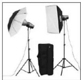
- Easy Softbox ESB 60-60
(Order No. 009016076)
Dimensions: 60 × 60 cm
Including front and background diffusers, carrying case and Bowens-compatible adapter to connect to a Metz TL or BL studio flash device.
- Easy Softbox ESB 40-40
(Order No. 009014047)
Dimensions: 40 × 40 cm
Including front and background diffusers, carrying case and Bowens-compatible adapter to connect to a Metz TL or BL studio flash device.
• Flash device holder FGH 40-60
(Order No. 009094065)
Adapter for compact flash devices and Easy Softboxes
Adjustable flash foot height
Connects to Metz lighting tripods LS-247 and LS-200
Disposal of batteries
Do not dispose of spent batteries with domestic rubbish.
Please return spent batteries to collecting points should they exist in your country!
Please return only fully discharged batteries.
Normally, batteries are fully discharged if:
- the device they powered switches itself off and indicates "Spent Batteries".
- they no longer function properly after prolonged use.
To ensure short-circuit safety please cover the battery poles with adhesive tape.
Errors excepted. Subject to changes!

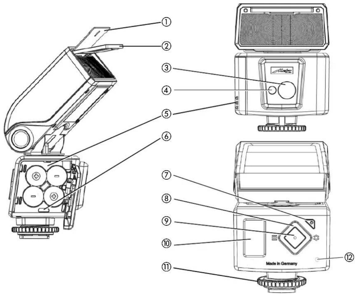
① Reflector card (recessed)
② Wide angle diffuser disk (recessed)
③ LED video light
④ AF auxiliary light
⑤ Battery compartment (4x AA – see safety information)
⑥ USB socket (micro)
⑦ ON / OFF button
lights up green when reaching the flash readiness
lights red in standby
⑧ Cursor keys:
◇ Selection of menu items and value adjustment
≡< Flash modes
◇ Options menu
⑨ Confirmation/info key
⑩ OLED display
⑪ Knurled nut
⑫ Integrated sensors for the remote mode
Premessa....180
REMOTE MASTER, cap. 10.1
REMOTE SLAVE, cap. 10.2
SERVO, cap. 10.3
F1 / F2, cap. 7.6
3.5 Il menu OPZIONI
- Press the ◇ ⑨ button and confirm the selected setting.
7.5 Luce video a LED
flowchart
graph TD
    A[">◇"] --> B["RATIO"]
    B --> C["MODE CHANNEL"]
    C --> D["◇"]
    D --> E["Hand pointing to the decision point"]
10.3 Modo SERVO
natural_image
Simple diagram with a pointing hand and a numbered label (①), no text or symbols present.Dimensioni approssimative in (L x H x P):
Ca. 65 x 94,1 x 86,8
Peso:
- Easy Softbox ESB 40-40
(art. no. 009014047)
① Misure: 40 × 40 cm
natural_image
Two identical hand icons pointing to the right, no text or symbols present
TTL HSS, consultar 7.4
M, consultar 7.3
M HSS, consultar 7.4
LED, consultar 7.5
REMOTE MASTER, consultar 10.1
REMOTE SLAVE, consultar 10.2
SERVO, consultar 10.3
F1 / F2, consultar 7.6
UNIT (metros/pies), consultar 14.2
RESET, consultar 15.3
MODE ^2) 3), consultar 10.1.2
natural_image
Simple diagram with two pointing hand icons and a label 'E' at the bottom (no text or symbols on the icons themselves)
flowchart
graph TD
    A["> サーフェ"] --> B["OPT. MODE CHANNEL ZOOM"]
    B --> C["◇"]
    C --> D["◇"]
    D --> E["CHANNEL 2 3 4 ◇"]
10.1.1 Ajustar modo maestro remoto
- Easy Softbox ESB 40-40
(N° ref. 009014047)
Dimensiones: 40 × 40 cm

Table 1: Guide numbers at maximum light output (P 1/1)
Tabel 1: Richsgetallen bid vol vermogen (P 1/1)
Your Metz product was developed and manufactured with high-quality materials and components which can be recycled and/or re-used.
GB
This symbol indicates that electrical and electronic equipment must be disposed of separately from normal garbage at the end of its operational lifetime.
Please dispose of this product by bringing it to your local collection point or recycling centre for such equipment.
This will help to protect the environment in which we all live.

Within the framework of the CE approval symbol, correct exposure was evaluated in the course of the electromagnetic compatibility test.
Do not touch the SCA contacts! In exceptional cases the unit can be damaged if these contacts are touched.
CE Avvertenza:
①
natural_image
Aerial view of an industrial complex with multiple factory buildings and adjacent water bodies (no visible text or signage)Metz mecatech GmbH • Ohmstraße 55 • 90513 Zirndorf / GERMANY • www.metz-mecatech.de • info@metz-mecatech.de

natural_image
Close-up of a metallic circular mechanical component with mounting base (no visible text or symbols)mecablitz
natural_image
Photography setup with two studio lighting equipment and a black box on tripod (no text or symbols visible)mecastudio
natural_image
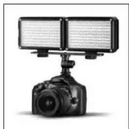
Black-and-white photo of a DSLR camera setup with dual-mounted screens mounted on a stand (no visible text or symbols)mecalight
Metz - always first class.

CE
716 47 0168.A1
D F NL GB I E


- - Easy Softbox ESB 40-40
- Le menu OPTIONEN
- Réglage du mode
- Indirect flitsen
- Gewicht :
- Manual flash exposure correction....150
- Introduction
- Proper Use
- Safety instructions
- Dedicated flash functions
- Preparing the flash unit for use
- Power supply
- Suitable batteries/rechargeable batteries
- Replacing batteries
- Mounting the flash unit
- Mounting the flash unit on the camera
- Removing the flash unit from the camera
- Switching the flash unit on and off
- The selection menu
- The OPTIONS Menu
- INFO
- Auto OFF for the flash unit
- Setting the automatic unit switch-off
- OLED displays on the flash unit
- Flash readiness indication
- Correct exposure indication
- Information in Display
- Display of the flash mode
- Range display
- Range display in TTL- and TTL HSS flash modes
- Range display in manual flash mode
- Exceeding the display range
- Displays in the camera viewfinder
- Flash symbol is illuminated:
- Flash symbol flashes slowly:
- Incorrect exposure guidelines:
- Flash modes
- AUTO Flash Mode
- Preflash TTL and ADI metering
- Setting the mode of operation
- Manual flash mode
- Manual partial light output levels
- Setting procedure
- Automatic high-speed synchronisation (HSS)
- Favorite programme
- Procedure for saving a favourite programme
- Procedure for loading a favourite programme
- Manual flash exposure correction
- Tip:
- Special functions
- Auto zoom
- Manual zoom mode
- In this case auto-zoom mode is not possible!
- Resetting to auto-zoom
- Wide-angle diffuser
- mecabounce Diffuser MBM-04
- Cordless flash mode
- Remote master mode settings
- Setting the remote channel
- Setting the flash mode type of the master
- Setting the flash unit type Remote TTL
- Setting the flash mode Remote M
- RATIO
- Activate / deactivate ratio
- Activating ratio
- Remote slave flash mode
- Remote slave flash mode settings
- Setting partial light output correction
- Setting partial light output/exposure correction
- SERVO mode
- Setting SERVO flash mode
- Pre-flash suppression or synchronisation settings
- Servo mode partial light output settings
- Remote channels cannot be set in SERVO mode. The camera flash unit may not work in the remote mode.
- Learn function
- Setting procedure for the learn function
- OPTION menu
- Automatic Zoom Operation (A-ZOOM)
- Manual Zoom Operation
- AF auxiliary light (AF-BEAM)
- Flash techniques
- Bounce flash
- Bounce flash with a reflector card
- Flash synchronisation
- Automatic flash sync speed control
- Normal synchronisation
- Slow synchronisation (SLOW)
- Second curtain synchronisation (2nd curtain, SLOW2)
- Display settings
- Brightness
- Range display in m or ft (UNIT)
- Care and maintenance
- Firmware updates
- Conditioning the flash capacitor
- Factory settings (RESET)
- Troubleshooting
- No maximum flash range indication appears on the display panel.
- The AF measuring beam of the flash unit is not activated.
- The reflector position is not automatically adjusted to the current zoom position of the lens.
- The TTL flash mode cannot be set.
- Automatic switching to the flash sync speed fails to occur.
- The shots are too dark.
- The shots are too bright.
- The setting for manual TTL flash exposure correction has no effect.
- Technical data
- Flash modes:
- Manual partial light output levels:
- Synchronisation:
- Light coverage:
- Swivelling ranges and locking positions of the reflector:
- | Video light:
- Weight :
- Included:
- Optional accessories
- • mecabounce Diffuser MBM-04
- - Flash unit mounting foot S60
- - Easy Softbox ESB 60-60
- • Flash device holder FGH 40-60
- Disposal of batteries
- Il menu OPZIONI
- Luce video a LED
- Modo SERVO
- Ajustar modo maestro remoto
- CE Avvertenza:
Brand : METZ
Model : Mecablitz M400
Category : Flash