FG 12SB - Grinder HITACHI - Free user manual and instructions
Find the device manual for free FG 12SB HITACHI in PDF.
| Technical Features | Not specified |
|---|---|
| Usage | Not specified |
| Maintenance and Repair | Not specified |
| Safety | Not specified |
| General Information | Not specified |
Frequently Asked Questions - FG 12SB HITACHI
User questions about FG 12SB HITACHI
0 question about this device. Answer the ones you know or ask your own.
Ask a new question about this device
Download the instructions for your Grinder in PDF format for free! Find your manual FG 12SB - HITACHI and take your electronic device back in hand. On this page are published all the documents necessary for the use of your device. FG 12SB by HITACHI.
USER MANUAL FG 12SB HITACHI
natural_image
Line drawing of a mechanical power tool with angular and radial components (no text or symbols)Read through carefully and understand these instructions before use. Diese Anleitung vor Benutzung des Werkzeugs sorgfältig durchlesen und verstehen. Lire soigneusement et bien assimiler ces instructions avant usage. Prima dell'uso leggere attentamente e comprendere queste istruzioni. Deze gebruiksaanwijzing s.v.p. voor gebruik zorgvuldig doorlezen. Leer cuidadosamente y comprender estas instrucciones antes del uso.

Handling instructions Bedienungsanleitung Mode d'emploi Istruzioni per l'uso Gebruiksaanwijzing Instrucciones de manejo
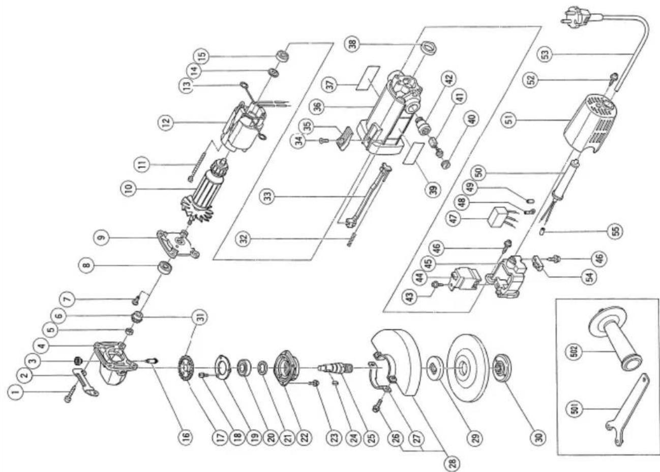
The exploded assembly drawing should be used only for authorized service center.
| Item No. | Part Name |
| 1 Tapping Screw D5 × 25 | |
| 2 Guard Plate | |
| 3 Pushing Button | |
| 4 Gear Cover Ass'y | |
| 5 Special Nut M7 | |
| 6 Pinion | |
| 7 Stotted Hd. Screw (Seal Lock)M4 × 10 | |
| 8 Ball Bearing (608VVMC2EPS2L) | |
| 9 Inner Cover | |
| 10 Armature | |
| 11 Hex. Hd. Tapping Screw D4 × 70 | |
| 12 Stator | |
| 13 Brush Terminal | |
| 14 Washer (A) | |
| 15 Ball Bearing (626VVMC2ERPS2S) | |
| 16 Lock Pin | |
| 17 Gear | |
| 18 Seal Lock Screw (W/Sp. Washer)M4 × 10 | |
| 19 Bearing Cover (B) | |
| 20 Ball Bearing (6001VVCMS2L) | |
| 21 Felt Packing | |
| 22 Packing Gland | |
| 23 Seal Lock Screw (W/Sp. Washer)M4 × 12 | |
| 24 Woodruff Key 2.5 × 8 | |
| 25 Spindle | |
| 26 Machine Screw (W/Sp. Washer)M5 × 16 | |
| 27 Set Plate | |
| 28 Wheel Guard Ass'y | |
| 29 Wheel Washer | |
| 30 Wheel Nut M14 | |
| 31 Gear Pinion Ass'y | |
| 32 Spring | |
| 33 Slide Bar | |
text_image
Exploded view diagram of a mechanical assembly with numbered parts for identification1
text_image
15° ~30° A B3
text_image
21 5 mm 12 mm ⑧ ⑨2
text_image
Exploded view diagram of a mechanical device with numbered parts for identification| English Deutsch Français | |||
| 1 | Wrench | Schlüssel | Clef |
| 2 | Wheel nut | Mutter für Schleifscheibe | Ecrou de la meule |
| 3 | Depressed center wheel | Schleifscheibe | Meule |
| 4 | Wheel washer | Unterlegscheibe | Rondelle de la meule |
| 5 | Wheel guard | Schutzhaube | Couvre-meule |
| 6 | Spindle | Spindel | Arbre |
| 7 | Lock pin | Sperrstift | Goupille de blocage |
| 8 | Wear limit | Verschleißgrenze | Limite d’usure |
| 9 | No. of carbon brush | Nr. der Kohlebürste | No. du balai en carbone |
| Italiano Nederlands Español | |||
| 1 | Chiave | Sleutel | Llave para tuercas |
| 2 | Dado ad anello | Moer voor de schuurschijf | Contratuerca molar |
| 3 | Mola | Schuurschijf | Muela de alisado |
| 4 | Rondella “grover” | Onderlegschijf | Arandela molar |
| 5 | Carter della mola | Beschermkap | Cubierta protector de muela |
| 6 | Asse | As | Eje |
| 7 | Spina di bloccaggio | Blokkeerstift | Pasador de cierre |
| 8 | Límite di usura | Slijtagegrens | Límite de uso |
| 9 | N. della spazzola di carbone | Nr. van de koolborstel | No. de carbón de contacto |
GENERAL OPERATIONAL PRECAUTIONS
WARNING! When using electric tools, basic safety precautions should always be followed to reduce the risk of fire, electric shock and personal injury, including the following.
Read all these instructions before operating this product and save these instructions.
For safe operations:
- Keep work area clean. Cluttered areas and benches invite injuries.
- Consider work area environment. Do not expose power tools to rain. Do not use power tools in damp or wet locations. Keep work area well lit. Do not use power tools where there is risk to cause fire or explosion.
- Guard against electric shock. Avoid body contact with earthed or grounded surfaces. (e.g. pipes, radiators, ranges, refrigerators).
- Keep children away. Do not let visitors touch the tool or extension cord. All visitors should be kept away from work area.
- Store idle tools. When not in use, tools should be stored in a dry, high or locked up place, out of reach of children.
- Do not force the tool. It will do the job better and safer at the rate for which it was intended.
- Use the right tool. Do not force small tools or attachments to do the job of a heavy duty tool. Do not use tools for purposes not intended; for example, do not use circular saw to cut tree limbs or logs.
- Dress properly. Do not wear loose clothing or jewellery, they can be caught in moving parts. Rubber gloves and non-skid footwear are recommended when working outdoors. Wear protecting hair covering to contain long hair.
- Use eye protection. Also use face or dust mask if the cutting operation is dusty.
- Connect dust extraction equipment. If devices are provided for the connection of dust extraction and collection facilities ensure these are connected and properly used.
- Do not abuse the cord. Never carry the tool by the cord or yank it to disconnect it from the receptacle. Keep the cord away from heat, oil and sharp edges.
- Secure work. Use clamps or a vice to hold the work. It is safer than using your hand and it frees both hands to operate tool.
- Do not overreach. Keep proper footing and balance at all times.
- Maintain tools with care. Keep cutting tools sharp and clean for better and safer performance. Follow instructions for lubrication and changing accessories. Inspect tool cords periodically and if damaged, have it repaired by authorized service center. Inspect extension cords periodically and replace, if damaged. Keep handles dry, clean, and free from oil and grease.
-
Disconnect tools. When not in use, before servicing, and when changing accessories such as blades, bits and cutters.
-
Remove adjusting keys and wrenches. Form the habit of checking to see that keys and adjusting wrenches are removed from the tool before turning it on.
- Avoid unintentional starting. Do not carry a plugged-in tool with a finger on the switch. Ensure switch is off when plugging in.
- Use outdoor extension leads. When tool is used outdoors, use only extension cords intended for outdoor use.
- Stay alert. Watch what you are doing. Use common sense. Do not operate tool when you are tired.
-
Check damaged parts. Before further use of the tool, a guard or other part that is damaged should be carefully checked to determine that it will operate properly and perform its intended function. Check for alignment of moving parts, free running of moving parts, breakage of parts, mounting and any other conditions that may affect its operation. A guard or other part that is damaged should be properly repaired or replaced by an authorized service center unless otherwise indicated in this handling instructions. Have defective switches replaced by an authorized service center. Do not use the tool if the switch does not turn it on and off.
-
Warning The use of any accessory or attachment, other than those recommended in this handling instructions, may present a risk of personal injury.
-
Have your tool repaired by a qualified person. This electric tool is in accordance with the relevant safety requirements. Repairs should only be carried out by qualified persons using original spare parts. Otherwise this may result in considerable danger to the user.
PRECAUTIONS ON USING DISC GRINDER
- Never operate these power tools without Wheel Guards.
- Use only a depressed center wheel with a "Safe Speed" of at least as high as the "No-Load RPM" indicated on the power tool nameplate.
- Always hold the body handle and side handle of the power tool firmly. Otherwise the counterforce produced may result in inaccurate and even dangerous operation.
- Do not work near welding equipment. If you work near welding equipment, rotation may become unstable.
- Ensure that blotters are used when they are provided with the bonded abrasive product and when they are required.
- Ensure that sparks resulting from use do not create a hazard e.g. do not hit persons, or ignite flammable substances.
- Do not use separate reducing bushings or adaptors to adapt large hole abrasive wheels.
SPECIFICATIONS
| Voltage (by areas)* | (110V, 115V, 120V, 127V, 220V, 230V, 240V) ∪ | |
| Power Input* | 550 W / 600 W | |
| No-load speed* | 11000/min | |
| Wheel | outer dia. × hole dia. | 115 × 22 mm |
| peripheral speed | 4800 m/min | |
| Weight (only main body) | 1.6 kg | |
*Be sure to check the nameplate on product as it is subject to change by areas.
STANDARD ACCESSORIES
(1) Wrench .... 1
(2) Side handle .... 1
Standard accessories are subject to change without notice.
APPLICATIONS
○Removal of casting fin and finishing of various types of steel, bronze and aluminum materials and castings.
○Grinding of welded sections or sections cut by means of a cutting torch.
○Grinding of synthetic resins, slate, brick, marble, etc.
PRIOR TO OPERATION
1. Power source
Ensure that the power source to be utilized conforms to the power requirements specified on the product nameplate.
2. Power switch
Ensure that the power switch is in the OFF position. If the plug is connected to a receptacle while the power switch is in the ON position, the power tool will start operating immediately, which could cause a serious accident.
3. Extension cord
When the work area is removed from the power source, use an extension cord of sufficient thickness and rated capacity. The extension cord should be kept as short as practicable.
4. Fitting and adjusting the wheel guard
The wheel guard is a protective device to prevent injury should the depressed center wheel shatter during operation. Ensure that the guard is properly fitted and fastened before commencing grinding operation. By slightly loosening the setting screw, the wheel guard can be turned and set at any desired angle for maximum operational effectiveness. Ensure that the setting screw is thoroughly tightened after adjusting the wheel guard.
- Ensure that the depressed center wheel to be utilized is the correct type and free of cracks or surface defects. Also ensure that the depressed center wheel is properly mounted and the wheel nut is securely tightened, Refer to the section on "Depressed Center Wheel Assembly"
6. Conducting a trial run
Before commencing grinding operation, the machine should be given a trial run in a safe area to ensure that it is properly assembled and that the depressed center wheel is free from obvious defects.
Recommended trial runs'duration are as follows: After replacing depressed center wheel .... 3 minutes or more
Prior to starting routine work 1 minute or more
7. Confirm the lock pin.
Confirm that the lock pin is disengaged by pushing lock pin two or three times before switching the power tool on (See Fig. 2).
3. Fixing the side handle.
Screw the side handle into the gear cover.
PRACTICAL GRINDER APPLICATION
1. Pressure
To prolong the life of the machine and ensure a first class finish, it is important that the machine should not be overloaded by applying too much pressure. In most applications, the weight of the machine alone is sufficient for effective grinding. Too much pressure will result in reduced rotational speed, inferior surface finish, and overloading which could reduce the life of the machine.
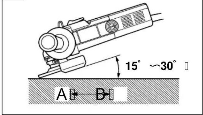
2. Grinding angle
Do not apply the entire surface of the depressed center wheel to the material to be ground. As shown in Fig. 1, the machine should be held at an angle of 15^-30^ so that the external edge of the depressed center wheel contacts the material at an optimum angle.
- To prevent a new depressed center wheel from digging into the workpiece, initial grinding should be performed by drawing the grinder across the workpiece toward the operator (Fig. 1 direction B). Once the leading edge of the depressed center wheel is properly abraded, grinding may be conducted in either direction.
4. Precautions immediately after finishing operation After switching off the machine, do not put it down until the depressed center wheel has come to a complete stop. Apart from avoiding serious accidents, this precaution will reduce the amount of dust and swarf sucked into the machine.
CAUTION
When the machine is not in use, the power source should be disconnected.
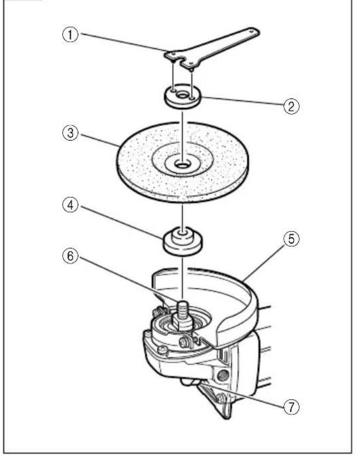
ASSEMBLING AND DISASSEMBLING THE DEPRESSED CENTER WHEEL (Fig. 2)
CAUTION: Be sure to switch OFF and disconnect the attachment plug from the receptacle to avoid a serious accident.
1. Assembling (Fig. 2)
(1) Turn the equipment upsidedown so that the spindle will be facing up.
(2) Mount the wheel washer onto the spindle.
(3) Fit the protuberance of the depressed center wheel onto the wheel washer.
(4) Screw from above the wheel nut onto the spindle.
(5) As shown in Fig. 2, push in the lock pin to prevent rotation of the spindle. Then, secure the depressed center wheel by tightening the wheel nut with the wrench.
2. Disassembling
Follow the above procedures in reverse.
CAUTIONS:
○Comfirm that the depressed center wheel is mounted firmly.
○Confirm that the lock pin is disengaged by pushing lock pin two or three times before switching the power tool on.
MAINTENANCE AND INSPECTION
1. Inspecting the depressed center wheel
Ensure that the depressed center wheel is free of cracks and surface defects.
2. Inspecting the mounting screws:
Regularly inspect all mounting screws and ensure that they are properly tightened. Should any of the screws be loose, retighten them immediately. Failure to do so could result in serious hazard.
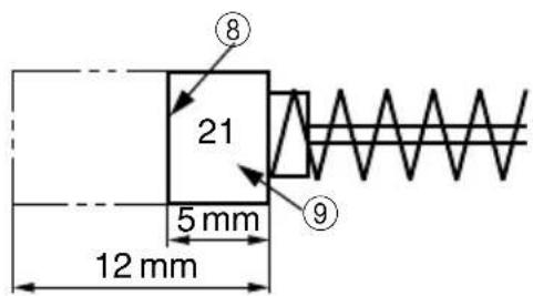
3. Inspecting the carbon brushes (Fig. 3)
The motor employs carbon brushes which are consumable parts. Since an excessively worn carbon brush can result in motor trouble, replace the carbon brush with a new one having the same carbon brush No. shown in the figure when it becomes worn to or near the "wear limit". In addition, always keep carbon brushes clean and ensure that they slide freely within the brush holders.
4. Replacing carbon brushes:
Disassemble the brush caps with a slotted-head screwdriver. The carbon brushes can then be easily removed.
5. Maintenance of the motor
The motor unit winding is the very "heart" of the power tool. Exercise due care to ensure the winding does not become damaged and/or wet with oil or water.
NOTE
Due to HITACHI's continuing program of research and development, the specifications herein are subject to change without prior notice.
IMPORTANT
Correct connection of the plug
The wires of the main lead are coloured in accordance with the following code:
Blue: -Neutral
Brown: -Live
As the colours of the wires in the main lead of this tool may not correspond with the coloured markings identifying the terminals in your plug proceed as follows:
The wire coloured blue must be connected to the terminal marked with the letter N or coloured black. The wire coloured brown must be connected to the terminal marked with the letter L or coloured red. Neither core must be connected to the earth terminal.
NOTE
This requirement is provided according to BRITISH STANDARD 2769: 1984.
Therefore, the letter code and colour code may not be applicable to other markets except The United Kingdom.
Information concerning airborne noise and vibration The measured values were determined according to EN50144.
The typical A-weighted sound pressure level: 90 dB (A).
The typical A-weighted sound power level: 103 dB (A).
Wear ear protection.
The typical weighted root mean square acceleration value does not exceed 2.5 m/s^2 .