CTDI K 940C NE - Cooker BAUKNECHT - Free user manual and instructions
Find the device manual for free CTDI K 940C NE BAUKNECHT in PDF.

User questions about CTDI K 940C NE BAUKNECHT
0 question about this device. Answer the ones you know or ask your own.
Ask a new question about this device
Download the instructions for your Cooker in PDF format for free! Find your manual CTDI K 940C NE - BAUKNECHT and take your electronic device back in hand. On this page are published all the documents necessary for the use of your device. CTDI K 940C NE by BAUKNECHT.
USER MANUAL CTDI K 940C NE BAUKNECHT
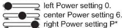
Module (Powermanagement)
4.23 Verriegelung
4.25 Powermanagement
1 Safety instructions and warnings 29
2 Instructions for assembly 32
2.1 Safety instructions for kitchen unit fi tters 32
2.2 Ventilation 32
2.3 Installation 32
2.4 Variable installation possibilities: Overlying installation 33
2.5 Variable installation possibilities: Flush installation 33
2.6 Illustrations kitchen cupboard.. 34
2.7 Making the worktop recess 35
2.8 Gluing in the hob 35
2.9 Extraction air system assembly 37
2.10 Important notes for fitting 38
2.11 7-pole fan plug connector 39
2.12 4-pole plasma filter plug connector (optional) ....39
2.13 Technical Data 40
2.14 Putting the appliance into operation 40
3 Appliance description 41
3.1 Operating the hob with the sensor keys 42
3.2 Worth knowing about the slider (sensorfi eld) 42
4 Operation 43
4.1 The induction hob 43
4.2 Pan recognition 43
4.3 Operation time limit 43
4.4 Other functions 43
4.5 Protection against overheating (induction) 43
4.6 Cookware for induction hobs 44
4.7 How to cut power consumption 44
4.8 Power settings 44
4.9 Residual heat display 44
4.10 Switching the appliance into the standby mode..45
4.11 Operating the keys 45
4.12 Switching on the hob and cooking zones 45
4.13 Switching off a cooking zone 45
4.14 Switching off the hob 45
4.15 Stop function 46
4.16 Recall function 46
4.17 Control panel lock 47
4.18 Bridging function 47
4.19 Automatic switch-off (timer) 48
4.20 Minute minder (egg timer) 48
4.21 Automatic boost function 49
4.22 Keep-warm function 49
4.23 Locking 50
4.24 Power boost 50
4.25 Power management 50
4.26 Using the fan 51
4.26.1 Switching the fan on and off 51
4.26.2 Fan time lag 51
4.26.3 Stop delay time 51
5 Cleaning and care 52
5.1 Glass ceramic hob 52
5.2 Specific soiling 52
5.3 Hob fan 52
5.4 Energy saving tips 52
6 What to do if trouble occurs? 53
7 Customer Service 53
THANK YOU FOR BUYING A BAUKNECHT PRODUCT
In order to receive a more complete assistance, please register your product on www.bauknecht.eu/ register
Before using the appliance carefully read the Safety Instruction.
1 Safety instructions and warnings
IMPORTANT TO BE READ AND OBSERVED
Download the complete instruction manual on docs.bauknecht.eu or call the phone number shown on the warranty booklet.
Before using the appliance, read these safety instructions. Keep them nearby for future reference.
These instructions and the appliance itself provide important safety warnings, to be observed at all times. The manufacturer declines any liability for failure to observe these safety instructions, for inappropriate use of the appliance or incorrect setting of controls.
Very young children (0-3 years) should be kept away from the appliance. Young children (3-8 years) should be kept away from the appliance unless continuously supervised. Children from 8 years old and above and persons with reduced physical, sensory or mental capabilities or lack of experience and knowledge can use this appliance only if they are supervised or have been given instructions on safe use and understand the hazards involved. Children must not play with the appliance. Cleaning and user maintenance must not be carried out by children without supervision.
WARNING: The appliance and its accessible parts become hot during use. Care shoul be taken to avoid touching heating elements. Children less than 8 years of age must be kept away unless continuously supervised.
CAUTION: Accessible parts of the hood may become hot when used with cooking appliances.
WARNING: If the hob surface is cracked, don't use the appliance - risk of electrical shock.
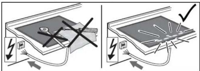
WARNING: Danger of fire: Do not store items on the cooking surfaces.
CAUTION: The cooking process has to be supervised. A short cooking process has to be supervised continuously.
WARNING: Unattended cooking on a hob with or oil can be dangerous - risk of fire. NEVER try to extinguish a fire with water, but switch off the appliance and then cover fl ame e.g. with a lid or a fire blanket.
Do not leave frying pans unattended when frying, as the frying oil may catch fire.
Do not use the hob as a work surface or support. Keep clothes or other flammable materials away from the appliance, unitl all the components have cooled down completely - risk of fire.
Metallic objects such as knives, forks, spoons and lids should not be placed on the hob surface since they can get hot.
After use, switch off the hob element by its control and do not rely on the pan detector.
PERMITTED USE
CAUTION: the appliance is not intended to be operated by means of an external switching device, such as a timer, or separate remote controlled system.
This appliance is intended to be used in household and similar applications such as: staff kitchen areas in shops, offices and other working environments; farm houses; by clients in hotels, motels, bed & breakfast and other residential environments.
This appliance is not for professional use. Do not use the appliance outdoors.
INSTALLATION
The appliance must be handled and installed by two or more persons - risk of injury. Use protective gloves to unpack and install - risk of cuts.
Installation, including water supply (if any) and electrical connections, and repairs must be carried out by a qualified technician. Do not repair or replace any part of the appliance unless specifically stated in the user manual.
- Keep children away from the installation site. After unpacking the appliance, make sure that it has not been damaged during transport. In the event of problems, contact the dealer or your nearest After-sales Service. Once installed, packaging waste (plastic, styrofoam parts etc.) must be stored out of reach of children - risk of suffocation. The appliance must be disconnected from the power supply before any installation operation - risk of electrical shock. During installation, make sure the appliance does not damage the power cable - risk of fire or electrical shock. Only activate the appliance when the installation has been completed.
Carry out all cabinet cutting works before fitting the appliance in the furniture and remove all wood chips and sawdust.
If the appliance is Not installed above an oven, a separator panel (not included) must be installed in the compartment under the appliance.
The premises where the appliance is installed must be sufficiently ventilated, when the kitchen hood is used together with other gas combustion devices or other fuels.
Exhaust air must not be vented through a flue used for removal of fumes produced by appliances burning gas or other fuels, but must have a separate outlet. All national regulations governing extraction of fumes must be observed.
ELECTRICALWARNINGS
It must be possible to disconnect the appliance from the power supply by unplugging it if plug is accessible, or by a multi-pole switch installed upstream of the socket in accordance with the wiring rules and the appliance must be earthed in conformity with national electrical safety standards.
Do not use extension leads, multiple sockets or adapters. The electrical components must not be accessible to the user after installation. Do not use the appliance when you are wet or barefoot. Do not operate this appliance if it has a damaged power cable or plug, if it is not working properly, or if it has been damaged or dropped.
If the supply cord is damaged, it must be replaced with an identical one by the manufacturer, its service agent or similarly qualified persons in order to avoid a hazard - risk of electrical shock.
WARNING! Failure to install the screws or fixing device in accordance with these instructions may result in electrical hazards.
Earthing of the appliance is compulsory. (Not necessary for class II hoods identified by the symbol (^*) on the specifi cations label).
CLEANING AND MAINTENANCE
WARNING: Ensure that the appliance is switched off and disconnected from the power supply before performing any maintenance operation; never use steam cleaning equipment - risk of electric shock.
Do not use abrasive or corrosive products, chlorine-based cleaners or pan scourers.
The hood must be regularly cleaned on both the inside and outside (AT LEAST ONCE A MONTH). This must be completed in accordance with the maintenance instructions provided in this manual.
Failure to observe the instructions for cleaning the hood and replacing the fi Iters may result in a fire.
DISPOSAL OF PACKAGING MATERIALS
- The packaging material is 100% recyclable and is marked with the recycle symbol
The various parts of the packaging must therefore be disposed of responsibly and in full compliance with local authority regulations governing waste disposal.
DISPOSAL OF HOUSEHOLD APPLIANCES
- This appliance is manufactured with recyclable or reusable materials. Dispose of it in accordance with local waste disposal regulations.
- For further information on the treatment, recovery and recycling of household electrical appliances, contact your local authority, the collection service for household waste or the store where you purchased the appliance. This appliance is marked in compliance with European Directive 2012/19/EU, Waste Electrical and Electronic Equipment (WEEE). By ensuring this product is disposed of correctly, you will help prevent negative consequences for the environment and human health.
- The symbol on the product or on the accompanying documentation indicates that it should not be treated as domestic waste but must be taken to an appropriate collection center for the recycling of electrical and electronic equipment.
ENERGY SAVING TIPS
- Switch ON the hood at minimum speed when you start cooking and kept it running for few minutes after cooking is finished.
- Increase the speed only in case of large amount of smoke and vapour and use boost speed(s) only in extreme situations.
- Replace the charcoal fiiter(s) when necessary to maintain a good odour reduction efficiency.
- Clean the grease fi iter(s) when necessary to maintain a good grease fi iter efficiency.
- Use the maximum diameter of the ducting system indicated in this manual to optimize efficiency and minimize noise.
DECLARATIONS OF CONFORMITY
- This appliance meets the Ecodesign requirements of European Regulations:- n.65/2014 and n.
- 66/2014 in conformity to the European standard EN 61591 and EN 60704-2-13.
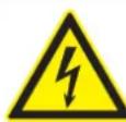
WARNING OF ELECTRICAL ENERGY RISK OF FATAL INJURY!
Live components have been installed near this symbol. Covers bearing this sign may only be removed by a certifi ed skilled electrician.
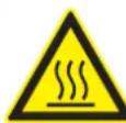
CAUTION! HOT SURFACES!
This symbol has been applied to surfaces which get hot. There is a risk of serious burning or scalding.
The surfaces may also be hot after the appliance has been switched off.

PLEASE NOTE
Note to be observed in order to make handling the appliance easier.
2 Instructions for assembly
2.1 Safety instructions for kitchen unit fitters
- The appliance must be handled and installed by two or more persons - risk of injury. Use protective gloves to unpack and install - risk of cuts.
- Veneers, adhesives and plastic surfaces of surrounding furniture must be temperature resistant (at least 75^ ). If the veneers and surfaces are not sufficiently heat resistant they may become deformed.
- Ensure that all live connections are safely insulated when installing the hob.
- Cover strips between the wall and the worktop behind the hob which are made of solid wood are permissible as long as minimum clearances in accordance with the installation diagrams are maintained.
- Minimum clearances of the hob cut-out towards the rear are to be maintained in accordance with the installation diagram.
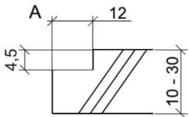
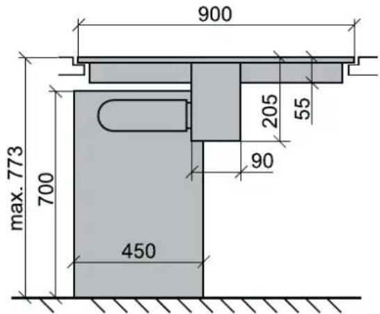
- For installation directly next to a tall cupboard, a safety distance of at least 50mm must be ensured. The side surface of the tall cupboard should be fitted with heat resistant material. Due to working requirements, however, the distance should be at least 300mm .
- The clearance between the hob and an extraction hood must be at least as large as that stipulated in the assembly instructions for the cooker hood.
- The packaging materials (plastic foil, polystyrene, nails etc.) must be kept out of reach of children as these parts are potentially dangerous. Small parts can be swallowed and there is a danger of plastic sheeting causing suffocation.
2.2 Ventilation
- The induction hob is fi tted with a fan that switches on and off automatically. The fan starts slowly when the electronic system temperatures exceed a specific limit. When the induction hob is used intensively, the fan will switch to a greater velocity. Once the electronic system has cooled down sufficiently, the fan will reduce its velocity and switch off again automatically.
- Clearance between the induction hob and kitchen furniture or built-in units must provide for sufficient ventilation of the induction hob.
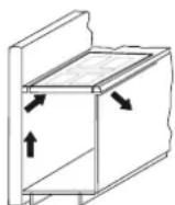
- If the power level of a cooking zone is automatically raised or lowered (see section on thermal cut-off device) it is likely that the cooling system does not cool sufficiently. In this case we recommend that the back wall of the bottom kitchen unit in the area of the worktop cut-out be opened and that the front transverse strip of the unit be removed over the entire width of the appliance in order to promote the circulation of air.
In order to better ventilate the hob, an air gap of 5mm should be left at the front.
2.3 Installation
Important information
- Avoid excessive thermal development from below e.g. from a baking oven without a cross flow cooling device.
- The induction hob may not be used when pyrolysis operation is taking place in a built-in oven.
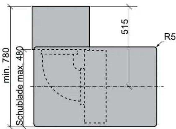
- When installing the appliance on top of a drawer it is essential to ensure that no sharp items are stored in the drawer since these could become bent on the underside of the hob and prevent the drawer from being opened and closed.
- If a shelf has been inserted underneath the hob, there must be a clearance of at least 20mm to the underside of the hob in order to ensure that the hob is sufficiently ventilated.
- The hob may not be installed above refrigerators, freezers, dishwashers, washing machines or dryers.
- To avoid danger of fire, make sure that no combustible objects which could easily catch fire or become deformed on exposure to heat are directly next to or under the surface.
Sealing of the hob
Before installation, correctly insert the sealing unit delivered with the hob.
- No liquids may penetrate between the edge of the hob and the worktop or between the hob and the wall and come into contact with any electrical appliances.
- When installing a hob into an uneven worktop, e.g. with a ceramic or similar covering (tiles etc.), the seal on the hob is to be removed and the seal between the hob and worktop made with plastic sealing materials (putty).
- The hob must under no circumstances be sealed with silicone sealant! This would make it impossible to remove the hob at a later date without damaging it.
Working surface cut-out
Cut out the worktop recess accurately with a good, straight saw blade or recessing machine. The cut edges should then be sealed so that no moisture can penetrate.
The area is cut out as illustrated. The glass ceramic hob must have a level and flush bearing. Any distortion may lead to fracture of the glass panel. Make sure that the sealing of the hob is properly seated.
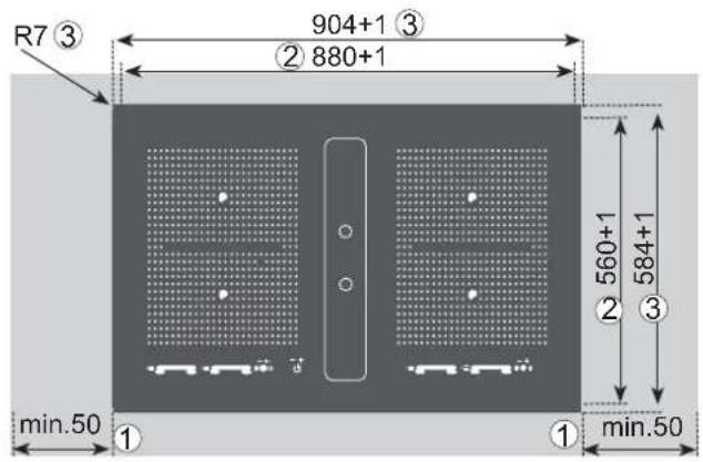
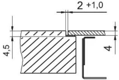
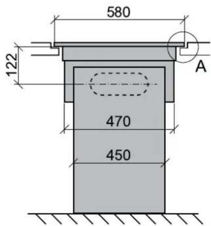
2.4 Variable installation possibilities: Overlying installation
Dimensions in mm
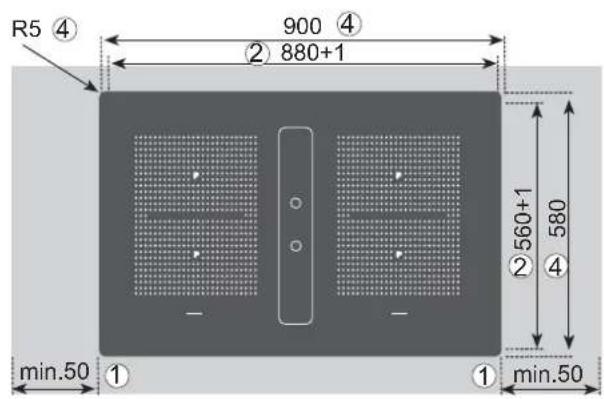
① Minimum distance to adjacent walls
② Opening dimensions
3 Cutout dimensions
Outer dimensions of the hob
Important:
There is a risk of breakage if the hob is canted or subjected to stress during installation!
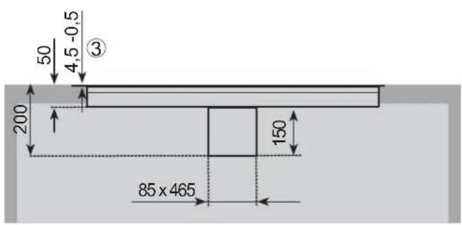
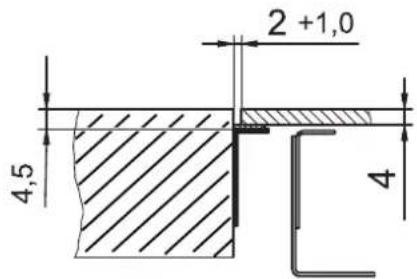
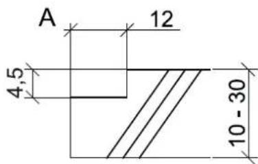
2.5 Variable installation possibilities: Flush installation
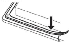
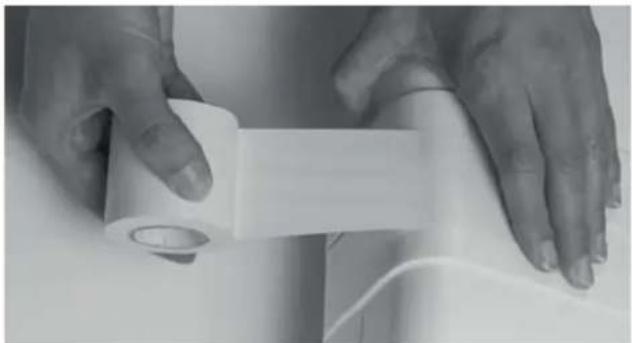
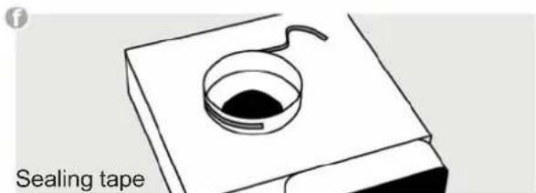
Glue the sealing tape onto the corner of the supporting edge of the worktop so that no silicone adhesive can be pressed under the hob.
Place the hob into the worktop cut-out without any adhesive and align it. Use shims if necessary
Fill the gap between the hob and the worktop with heat-resistant silicone adhesive.
Important
Silicone adhesive must not get under the support surface. If this occurs it will not be possible to remove the hob again at a later stage. No liability will be assumed in the case of failure to observe these instructions.
2.6 Illustrations kitchen cupboard.
2.7 Making the worktop recess
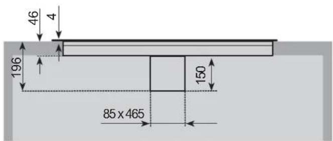
The cut-out is produced in two work steps.
- Making the opening for the base trough.
- Making the recess for the support of the glass ceramic hob.
(For this recess at least one recessing machine with guide strip is required.)
The outside dimension of the recess should always be about 6mm longer than the outside dimension of the glass ceramic hob so that a seal can be provided (see: Gluing in the hob).
Alternatively, instead of carrying out the second stage, the support of the glass ceramic hob can be cut out completely and then glued in again with the height adjusted.
It is also possible to install strips of wood or stone as well as steel angles.
- Make the opening for the hob.
- Fix the strip of wood or stone or the supporting angle onto the worktop.
Please note
In order to ensure that it is exactly fl ush with the stone worktop, the recess may have to be modifi ed accordingly.
2.8 Gluing in the hob
Notes
- In order to avoid damage to the worktop and the hob, it is necessary to glue the system worktop/hob with a permanent seal so that it is water-proof.
- The parts to be glued together must be dry and free from grease.
To glue the hob, you require the water-proof wash primer and the heat and moisture-resistant silicone adhesive (150^)
It is absolutely necessary to observe the remarks concerning these two products.
There you will also find a calculation formula for the hardening of the silicone adhesive. Do not operate the cooking zone before the hardening process is over as otherwise the silicone adhesive can be damaged.
Only glue the hob on its outer edges!
- Never place the hob with the glass ceramic surface unprotected on the worktop or the floor. Dirt (metal chips, small pieces of stone etc.) can cause scratches in the surface of the glass ceramic hob. Please always place it on cardboard or a wool rug.
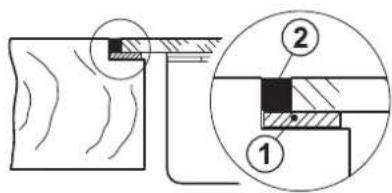
Procedure
- Glue the sealing tape ⑥ to the corner of the supporting edge of the worktop so that no silicone adhesive ② can be pressed under the hob.
Important: Only use the sealing tape that is supplied with the hob! Should you use any other sealing there is no guarantee that the hob will not sink down after installation. - Insert the hob without adhesive into the worktop opening and check the height If necessary, place the shims provided on the support edge for the hob at equal distances to adjust the height.
- Remove the hob again.
- Use the wash primer to pre-treat the outer edges of the hob and the side cut surfaces of the worktop where they have been glued.
Apply a thick coat of the primer with a brush on highly absorbent surfaces (e.g. chipboard). With less absorbent surfaces (e.g. marble or granite) it is suffi cient to apply the primer with a felt cloth.
Important: After application, the primer must be left for about 30 minutes.
- Now insert the hob and align.
- Finally, fill the gap between the hob and the worktop with silicone adhesive ②
- Smooth the joint with a spatula and water containing a little washing-up liquid.
Attention: Use sealing tape Silicone adhesive must not get under the support surface. If this occurs it will not be possible to remove the hob again at a later stage. No liability will be assumed in the case of failure to observe these instructions.


Island installation
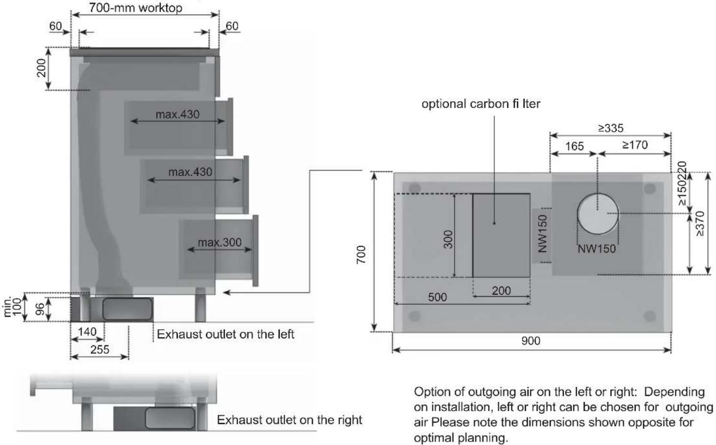
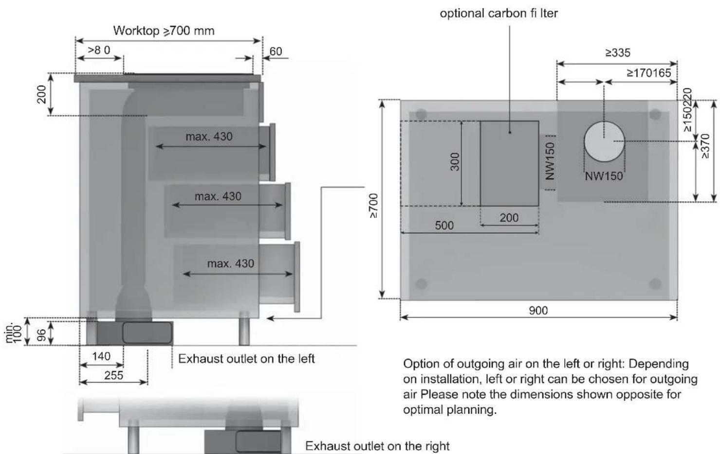
2.9 Extraction air system assembly
The hob and the fan can be connected with a fl exible hose or a fl at duct.
Shorten the fl at duct with a fi ne saw if necessary.
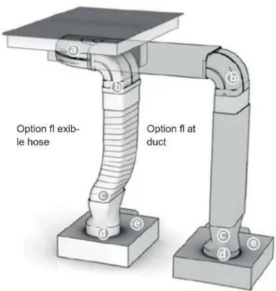
On point c
The fl exible connection piece is used for a worktop thickness of 600~mm . Please make sure that installation is as taut and crease-free as possible by shortening excess material.
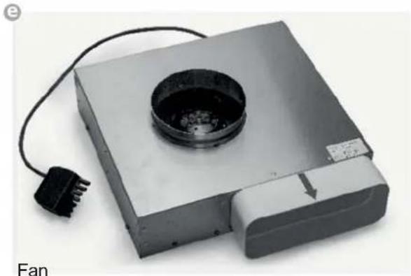
On point f
Apply sealing tape to the plinth fan connecting pieces (f) before attaching the adapter piece (d) to the plinth fan (e).
Important:
The components must all be firmly fastened as shown with the adhesive tape enclosed after they have been attached.
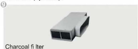
Exhaust air duct components (optional):
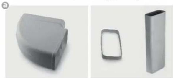
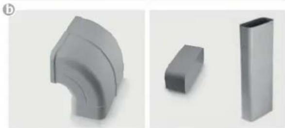
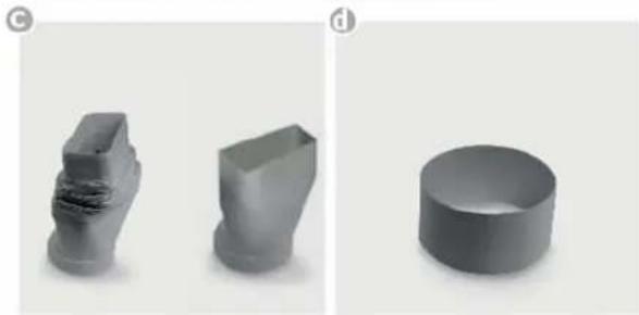
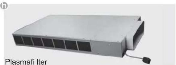
Plinth fi Iter (optional):
2.10 Important notes for fitting
- The appliance must be handled and installed by two or more persons - risk of injury. Use protective gloves to unpack and install - risk of cuts.
- Keep children away from the installation site.
- After unpacking the appliance, make sure that it has not been damaged during transport. In the event of problems, contact the dealer or your nearest After-sales Service.
- Once installed, packaging waste (plastic, styrofoam parts etc.) must be stored out of reach of children - risk of suffocation.
- The appliance must be disconnected from the power supply before any installation operation - risk of electrical shock. During installation, make sure the appliance does not damage the power cable - risk of fire or electrical shock. Only activate the appliance when the installation has been completed.
- Carry out all cabinet cutting works before ftting the appliance in the furniture and remove all wood chips and sawdust.
- If the appliance is Not installed above an oven, a separator panel (not included) must be installed in the compartment under the appliance.
- The cross-section of wall vents and the cut-out in the base panel should should at least correspond to the exhaust air pipe. The outflow opening must be at least 500~cm^2 . Reduce the height of the skirting boards or make corresponding openings.
- When installing the appliance make sure that the convection air unit is still accessible when the kitchen has been completely installed. If necessary levelling feet for the kitchen units must be moved.
- The hob fan can be operated in the extraction air and recirculation air mode.
- Lead the outgoing air outside through a ventilation shaft intended for this purpose or through the wall of the building.
- Outgoing air may not be led into a smoke or exhaust gas flue which is in operation. Contact the district master chimney sweep if you are in any doubt.
- A suffi cient supply of inlet air must be provided if a wood, coal, gas or oil heater requiring a chimney is operated in the environment of the hob fan, since an insufficient supply of air results in a risk of poisoning. The safe operation of the hob fan is guaranteed when the negative pressure resulting from the hob fan does not exceed 0.04 mbar (4 Pa) and a suffi cient supply of inlet air can flow into the room.
- Exhaust air pipes must comply with fire class B 1 DIN 4102. Please make sure that the minimum nominal width of the appliance connecting pieces is not reduced.
-
The Naber Compair Flow 150 system recommended for the airflow and compatible with the hob extractor should always be used.
The nominal width of the recirculation air pipe should not be less than 150~mm -
Exhaust air pipes should be as short as possible. They should not have a 90-degree angle; instead they should have soft bends and no reductions in their cross-section.
- Never use pipes with a diameter of less than 150~mm . No bends/ angles may be laid 50~cm before the fan module.
Always insert a straight piece of approx. 50~cm between two angles/bends.
Assembly
- Please observe the generally valid power plant and fire authority requirements.
- Installation/connection by qualifi ed staff members
- No claims for damage caused by failure to observe this document and/or the documents enclosed with the appliance may be enforced against the manufacturer.
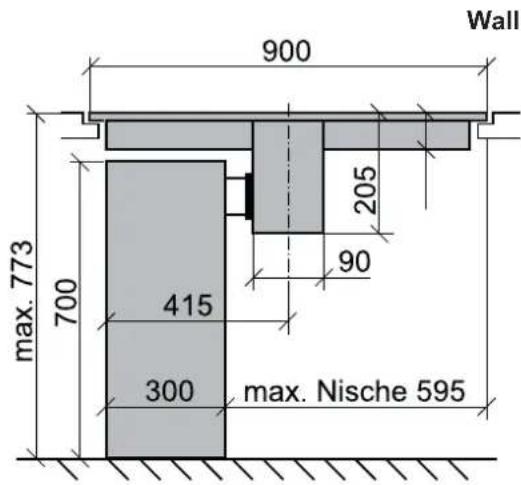
- Observe minimum clearances to walls: on the side at least 100mm and at the back at least 50mm .
Preparing the table cut-out
- Mill around the cut-out or produce it with strips of wood.
- Cut-outs accurate to dimension and right-angled.
- Ensure the correct height, so that the hob and the fi liter unit fit exactly.
Take recess ventilation of at least 400cm^2 into account on the side. - Units and covers must be temperature-resistant (< 75°C).
- Only plan for the fi iter set to be on the left.
- Place the unit (charcoal or plasma) into the niche.
- Align the air vents, faster.
- Establish an electrical connection.
- Insert the hob, align.
- Do not operate the hob while the silicone is hardening.
Test the primer/adhesive for usability before gluing. - Do not screw the hob tight as it weighs 18kg (fi liter not included).
- Combustible walls/ceilings above hobs must be fitted with fire-resistant cladding according to the relevant fire department organs.
Connecting to the electric power supply
- Only switch the safety fuses/main switch on once the hob has been installed/wired.
- Mount the enclosed sign in a clearly visible position since this will no longer be accessible after installation.
- Combustible walls/ceilings above hobs must be fitted with fire-resistant cladding according to the relevant fire department organs.
- Install the hob properly to ensure its protection against accidental contact.
- The charcoal or plasma fiiter must be installed so that it is always conveniently and easily accessible for servicing purposes.

PLEASE NOTE
When the convection air mode is in operation, ventilation must be suffi cient in order for the air humidity to be removed.
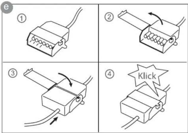
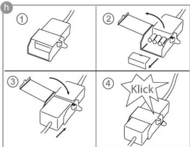
2.11 7-pole fan plug connector
Procedure
Connect the two 7-pole plus for the fan connection.
Open the plug retainer on the 7-pole plug (fan) of the hob and attach the 7-pole fan mating connector (e) until it is securely engaged. Then close the plug retainer again.
After installation, fit the connectors on the rear panel or in the shelf unit.
2.12 4-pole plasma fiiter plug connector (optional)
Procedure
Open the plug connections on the 4-pole plug (plasma) of the hob and remove the protective covers. Attach the plug to the 4-pole mating plug of the plasma filter (g) until it has firmly engaged.
Then close the plug retainer again.
After installation, fit the connectors on the rear panel or in the shelf unit.
WARNING OF ELECTRICAL ENERGY! RISK OF FATAL INJURY!
Live components have been installed near this symbol. Covers bearing this sign may only be removed by a certifi ed skilled electrician.
The electrical connection must be carried out by a qualifi ed electrician who is authorised to carry out such work!
Statutory regulations and the connection specific cations issued by the local power supply company must be strictly observed.
- When connecting the appliance it must be ensured that there is a device which makes it possible to universally disconnect it from the mains with a contact opening width of at least 3mm . Line-protecting switches, fuses or contactors are suitable cut-out devices. When connecting and repairing the appliance disconnect it from the electricity supply with one of these devices.
- The earth wire must be sufficiently long so that if the strain relief fails, the live wires of the connecting cable are subjected to tension before the earth wire.
- Any superfluous cable must be removed from the installation area beneath the appliance.
- Make sure that the local mains voltage is the same as the voltage on the rating label.
Full protection against accidental contact must be ensured on installation.
- Attention: Incorrect connection may result in the power electronics unit being destroyed.
- The appliance is only authorised for permanent connection. It may not be connected with a shock-proof plug.
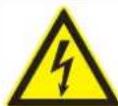
Power supply
Mains voltage: 380-415V 3N~, 50/60Hz
Component rated voltage: 220-240V
Mains cable available in the factory
- The hob has been fitted with a temperature-resistant connection cable in the factory.
- Connection to the mains is carried out in accordance with the circuit diagram, unless the connection cable is already fitted with a plug.
- If the mains cable of this appliance is damaged it will need to be replaced with a special connection cable. In order to avoid any risks, this must be carried out by the manufacturer or his Customer Service.
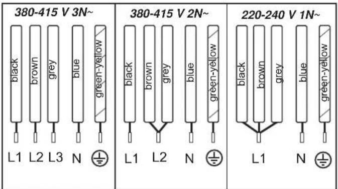
Electrical connections
2.13 Technical Data
| Hob dimensions height/ width/ depth ...mm 20 | 0 x 900 x 580 |
| Cooking zones all zones ............cm / kW 19 | x22/ 2,2 (3,7)* |
| Hob .....................kW Fan .....................kW Plasma .....................kW | 7.4 0.115 0.01 |
- Power when the power boost function is activated
2.14 Putting the appliance into operation
Once the hob has been installed and the power supply has been provided (mains connected) an automatic test of the controls will be carried out and information for Customer Service will be indicated.
Important: No items may be on the touch control sensor keys when the appliance is being connected!
Briefly wipe over the surface of the hob with a sponge and soapy water and then dry with a clean cloth.
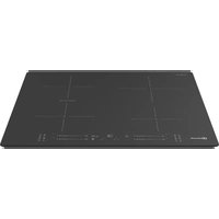
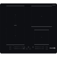
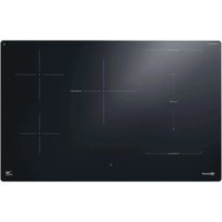
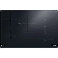
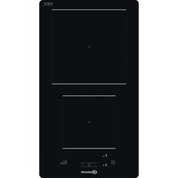
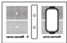
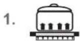
3 Appliance description
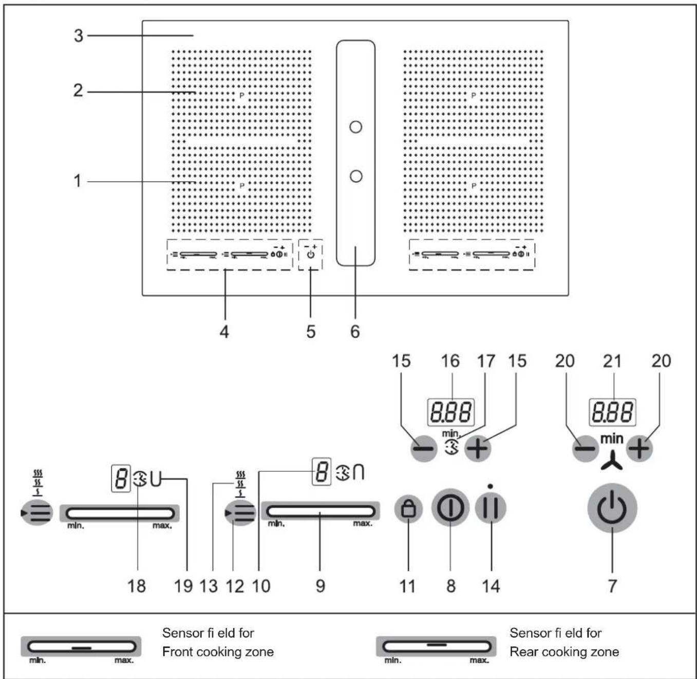
The decorative design may deviate from the illustrations.
- Front induction cooking zone
- Rear induction cooking zone
- Glass ceramic hob
- Touch-Control panel
- Standby key and fan controls
- Fan
- Standby key
- ON/OFF key (hob)
-
Sensor field
-
Power setting display
- Lock key
- Warming key
- Display of keep-warm function (3 levels)
- Stop key (pause)
- Minus key /Plus key Timer
- Timer indication
- Symbol egg timer
- Display cooking zone timer
- Bridging function
- Minus key /Plus key Ventilation
- Fan indicator
3.1 Operating the hob with the sensor keys
The glass ceramic hob is operated with touch control sensor keys. The sensor keys are operated as follows: lightly touch a symbol on the surface of the ceramic glass plate. A buzzer will indicate when the controls have been operated correctly.
The touch control sensor key will then be indicated as "key".
Standby key (7)
This key is used to switch the entire hob operational. It is, as it were, the main switch. When the hob has been switched off with this key, it will remain on standby for approx. another 120 min.
Attention! The residual heat indicator will no longer operate when the appliance has completely switched off.
ON/OFF key 8) Cooking zones left or right
This key is used to switch the respective cooking hob side left or right on and off.
Power setting display B10)
The power setting indicator shows the power setting which has been selected, or:
H Residual heat
P .........Power boost
Pan recognition
Automatic boost function
11.....Stop function
U....Keep-warm function
Control panel lock
Symbols
5 55 555 .........Keep-warm levels 42^ / 70^ / 94^
Timer function, automatic switch-off device
3 .Minute minder
UN........Bridging function
Lock key (11)
The lock key can be used to lock all of the keys.
Keepwarmkey·12)
For melting, holding and simmering
Power boost in the sensor fi eld
The power boost setting makes additional power available for induction cooking zones.
Stop key | (14)
The STOP function can be used to briefly stop the cooking process.
Recall function | (14) (recovery function)
The most recent setting can be recovered if the hob is switched off unintentionally.
Minus key +Plus key Ventilation (20)
With this keys the power levels of the fan are selected and the fan run is set.
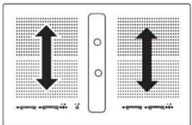
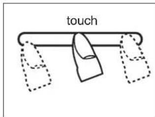
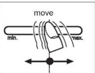
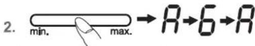
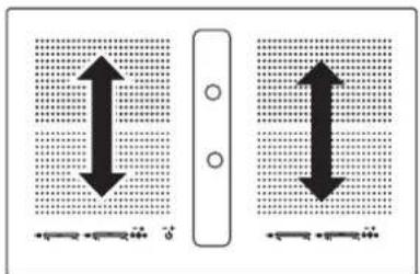
3.2 Worth knowing about the slider (sensorfi eld)
In principle, the slider functions the same as the touch controls; the only difference is that you can put your finger on the glass ceramic surface and then move it around. The sensor fi eld recognises this movement and raises or lowers the display setting (power level) in accordance with the movement.
The term sensor fi eld is used to mean slider from now on.

Sensor fi eld
What must be observed when operating sensor fields?
Your finger should not be placed flat onto the glass ceramic surface in order to avoid adjacent keys/sensor fi elds from reacting by mistake.
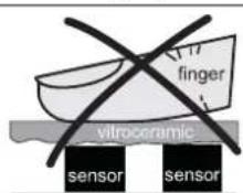
unsuitable
right
Press the sensor fi eld lightly or move your finger around
You can press the sensor fi eld very lightly with your finger; when this is done the setting on the display (power level) will gradually change.
When you put your finger on the sensor fi eld and then move it to the left or right, the display setting will change progressively.
The faster the movement, the faster the change in the display.
4 Operation
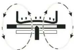
4.1 The induction hob
The hob is equipped with an induction cooking mode. An induction coil underneath the glass ceramic hob generates an electromagnetic alternating fi eld which penetrates the glass ceramic and induces the heat-generating current in the pot base.
With an induction cooking zone the heat is no longer transferred from a heating element through the cooking pot into the food being cooked; instead the necessary heat is generated directly in the container by means of induction currents.
Advantages of the induction hob
- Energy-saving cooking through the direct transfer of energy to the pot (suitable pots/pans made of magnetisable material are required).
- Increased safety as the energy is only transferred when a pot is placed on the hob.
- Highly effective energy transfer between an induction cooking zone and the base of a pot.
Rapid heat-up. - The risk of burns is low as the cooking area is only heated through the pan base; food which boils over does not stick to the surface.
Rapid, sensitive control of the energy supply.
4.2 Pan recognition U
If a cooking zone is switched on and there is no pan on the zone or if the pan is too small, there will be no transmission of power. A blinking in the power level indicator points this out.
If a suitable pot or pan is placed on the cooking zone, the power setting will switch on and the power setting indicator will light up. The power supply will be cut off when the pan is removed and the power setting indicator will indicate a blinking
If the pots and pans placed on the cooking zone are of smaller dimension, and the pan recognition still switches on, less power will be supplied.
Pan recognition limits
| Cooking zone diameter (mm) | Recommended minimal diameter pan base (mm) |
| 220 x 190 115 |
The base of pots and pans must be of a certain diameter; if it is not, the induction heat will not be switched on. Always place pots and pans in the middle of a cooking zone in order to achieve the best efficiency.
Important: The minimum diameter required to activate the pan recognition device may vary according to the type of pot or pan used!
4.3 Operation time limit
The induction hob has an automatic time limit function. The duration of continuous use of each cooking zone o pends on the cooking level selected (see chart).
This requires that the setting of a respective cooking zone is not adjusted during use.
If the operation time limit has been activated, the cooking zone will switch off, a short signal will sound and an H will appear in the display.
The automatic switch-off function overrules the operation time limit, i.e. the cooking zone is only switched off when the period of time of the automatic switch-off device has expired (e.g. automatic switch-off after 99 minutes and cooking level 9 is possible).
Operation time limit
| Selected cooking level | Operation time limit in minutes |
| 5555 | 120 |
| 1 | 520 |
| 2 | 402 |
| 3 | 318 |
| 4 | 260 |
| 5 | 212 |
| 6 | 170 |
| 7 | 139 |
| 8 | 113 |
| 9 | 90 |
| P | 10 |
4.4 Other functions
If two or more sensor keys are pressed at the same time (e.g. when a pan is mistakenly put onto a sensor key) no function will be activated.
The symbol will blink and a time-limited continuous signal will sound. After a few seconds the appliance will switch off. Please remove the item located in front of the sensor keys.
To delete the symbol, press the same key or switch the hob off and on.
4.5 Protection against overheating (induction)
If the hob is used at full power for a longer period, it will not be possible to cool down the electronics system as required at a high room temperature.
In order to ensure that no excessive temperatures occur in the electronics system the power of the cooking zones may be reduced automatically. Should E2 be displayed frequently during normal use of the hob and at normal room temperature, it is likely that cooling is not suffi cient.
This may occur if kitchen units have no openings. The installation may have to be checked (see the section on Ventilation).
4.6 Cookware for induction hobs
Cookware for induction cooking zones must be made of metal and have magnetic properties. The base must be sufficiently large.
Only use pots with a base suitable for induction.
| Suitable cookware Unsuitable cookware |
| Enamelled steel pots with a thick base |
| Cast iron pots with an enamelled base |
| Pots made of multi-layer stainless steel, stainless ferrite steel and aluminium with special base |
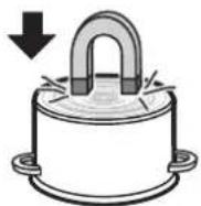
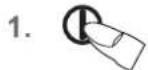
This is how to establish the suitability of a pot:
Conduct the magnet test described below or make sure that the pot bears the symbol for suitability for cooking with induction current.
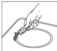
Magnet test:
Move the magnet towards the base of your cookware. If it is attracted, you can use the cookware on the induction hob.
Please note:
When using pans suitable for induction from certain manufacturers, noises may occur which are attributable to the design of these pans.
Wrong: the base of the pan is curved. The electronic unit cannot determine the temperature correctly.
4.7 How to cut power consumption
The following are a few useful hints to help you cut your consumption of energy and use your new induction hob and the cookware effi ciently.
- The base of your cooking pots should be the same size as the cooking zone.
- When buying cooking pots, note that it is frequently the diameter of the top of the pot that it indicated. This is usually larger than the base of a pot.
- Pressure cookers are particularly low on energy and time required thanks to the pressure and the fact that they are tightly closed. Short cooking times mean that vitamins are preserved.
Always make sure that there is sufficient fluid in your pressure cooker since the cooking zone and the cooker may be damaged as a result of overheating if the pressure cooker boils dry. - Always close cooking pots with a suitable lid.
- Use the right pot for the quantity of food you are cooking. A large pot which is hardly filled will use up a lot of energy.
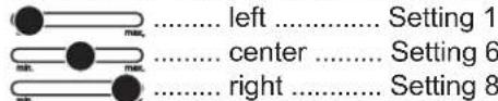
4.8 Power settings
The heating power of the cooking zones can be set at various power levels. In the chart you will find examples of how to use each setting.
| Setting Suitable for | |
| 0 | Off, using residual heat |
| U | Melting 42°C |
| U | Keeping warm 570°C |
| U | Cooking 594°C |
| 1-2 | Simmering small portions |
| 3 | Simmering level |
| 4-5 | Simmering larger quantities or roasting larger pieces of meat until they are cook-ed through |
| 6 | Roasting, getting juices |
| 7-8 | Roasting |
| 9 | Bringing to the boil, browning, roasting |
| P | Power boost (highest power output) |
A higher power level may need to be selected for cooking pots without a lid.
4.9 Residual heat display
The glass ceramic hob is equipped with an H as a residual heat indicator.
As long as the H lights up after the cooking zone has been switched off, the residual heat can be used for melting food or for keeping food warm.
The cooking zone may still be hot when the letter H no longer lights up. Risk of burns!
The glass ceramic is not directly heated in the case of an induction cooking zone; it is only heated up by heat reflected by the pan.
Suitable for induction cooking
4.10 Switching the appliance into the standby mode
This standby key is used to switch the entire hob operational. It is, as it were, the main switch. An automatic test of the controls will be carried out first of all, and the displays will light up briefly.
When the hob has been switched off with this key, it will remain on standby for approx. another 120 min.
Attention! The residual heat indicator will no longer operate when the appliance has completely switched off.
4.11 Operating the keys
The controls described here expect the pressing of a (selection) key to be followed by the pressing of a subsequent key.
The next key will need to be pressed within 10 seconds, otherwise the selection will be deleted.
4.12 Switching on the hob and cooking zones
- Press the ON/OFF key (approx. 1 sec.) until the power setting 0 appears and a short signal will sound. The controls are ready for operation.
- The sensor field of a cooling zone must be activated immediately afterwards. A power setting will be switched on.
See the section on Worth knowing about the slider (sensor fi eld)
Press the respective sensor fi eld to change a power setting or to switch on an additional cooking zone.
- Immediately put cookware suitable for induction cooking onto the cooking zone. The pan recognition device will activate the induction coil. The pot or pan will be heated up.
As long as no cooking pot is placed onto the cooking zone, the display will alternate between the power level set and the symbol r . If no pot is placed on the cooking zone it will switch off after 10 minutes for reasons of safety. Please refer to the Section on pan recognition.
4.13 Switching off a cooking zone
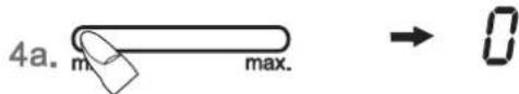
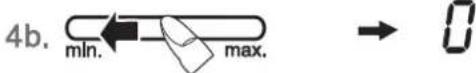
- a) Press the touch control (the fap left or b) drag your finger to the left across the touch control to reduce the power setting to 0
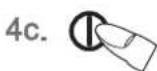
c) press the ON/OFF key of the cooking zones left or right. All the cooking zones are switched off.
4.14 Switching off the hob
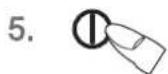
- Press the ON/Off key of the hob①The hob will be switched off, irrespective of any settings.
Please note:
The hob will switch off automatically after 10 seconds when all the cooking zones are switched of manually (power setting 0) and no key/sensor fi eld is pressed afterwards.
-
The Power boost function is activated immediately. See the section on Power setting.
- 1
4.15 Stop function
The cooking process can be briefly interrupted with the STOP function, e.g. if the doorbell rings. The STOP function must be released in order to continue cooking at the same power level. If a timer has been set it will pause and will then continue.
This function is only available for 10 minutes for reasons of safety. The hob will then be switched off.
- Pots and pans are on the cooking zones and the required power levels have been set.
- Press the Stop key I. Instead of the selected power settings, the interval sign will light up.
- The interruption is ended by firstly pressing the STOP key and then the fl ashing sensor fi elld left of the STOP key I.I
When operating the sensor fi eld slide over the complete sensor fi eld.
The second key must be pressed within 10 seconds, otherwise the stop function will be maintained.
4.16 Recall function
(recovery function)
The most recent setting can be recovered if the hob is switched off unintentionally.
The recall function only works if at least one cooking zone is switched on.
- The hob is inadvertently turned off by the ON/OFF key of the hob ①
- Within 6 seconds after turning it off, press the ON/OFF key of the hob again. The stop key LED will blink. The STOP key I must be pressed immediately afterwards.
The original cooking levels are restored. The cooking process continues.
What can be restored:
- Cooking levels of all cooking zones
- Minutes and seconds of programmed timer functions
Automatic boost function
Power boost
Not to be restored:
Operation time limit (it is counted from 0)
4.17 Control panel lock
The control panel lock serves the purpose of preventing children from switching on the induction hob either accidentally or intentionally. The controls are blocked here.
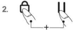
Switching on the control panel lock
- Press the ON/OFF key of the hob (approx. 1 sec.) in order to switch the entire hob on.
- Immediately afterwards press the Lock key and the STOP key | simultaneously.
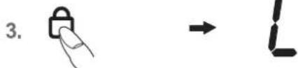
- Then press the Lock key in order to activate the control panel lock. The power setting indicators will show an L for control panel lock, the controls will be disabled and the hob will switch off.
Switching off the control panel lock
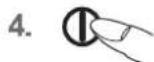
- Press the ON/Off key of the hob①
- Immediately afterwards press the Lock key and the STOP key simultaneously.
- Then press the Stop key | In order to deactivate the control panel lock. The L will go off.
De-activating the control panel lock for one cooking procedure only
This is only possible if the control panel lock has been switched on according to points 1-3.
- Press the ON/Off key of the hob ①
- Immediately afterwards press the Lock key and the STOP key simultaneously. Now the user will be able to switch on a cooking zone. When the hob is switched off the control panel lock will be activated again (switched on).
Notes
- In the event of a power cut the control panel lock will be cancelled, i.e. deactivated.
4.18 Bridging function
The front and the rear cooking zones may be activated together for a cooking process (bridging function). This enables larger cookware to be used.
- Switch on the hob.
- Press the sensor fi eld of the rear and front cooking zones simultaneously to activate the bridging function. The bridging function is activated, the symbol UN appears. Operation is carried out with the sensor fi eld of the front cooking zone.
- To deactivate the two sensor fields, press them simultaneously again or switch off the hob.
Please note
The roaster or the pot will need to cover at least half of the cooking zones used in order to be recognised by the pan recognition device!
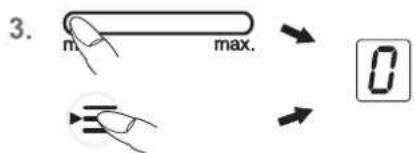
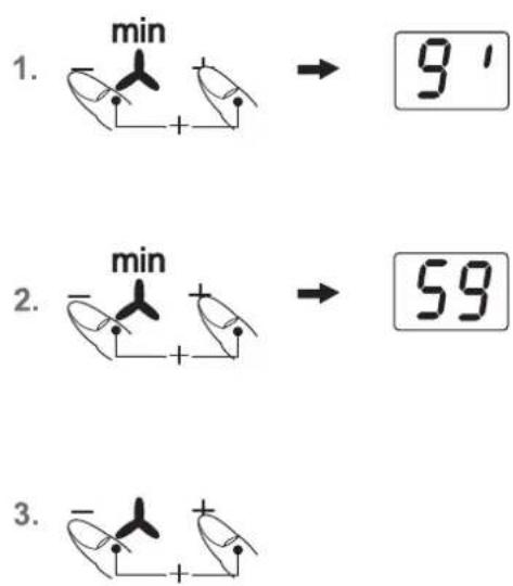
4.19 Automatic switch-off (timer)
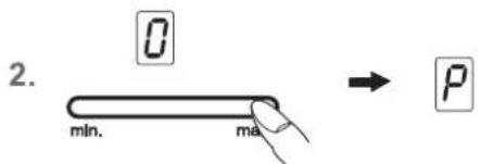
The automatic switch-off device is used to automatically switch off any cooking zone after an adjustable period of time. Cooking times ranging from 10 seconds (0.10) to 1 hour and 59 minutes (1.59) can be set.
- 1x,2x,3x.. mIn. max.
- 一
-
一 +
-
Switch on the hob. Switch on one or more cooking zones and select the required power settings.
- Press the Plus + and Minus-key -simultaneously until the symbol for the desired cooking zone lights up.
- To set the time press the Plus-+or Minus-key . After a few seconds your input will be assumed and the procedure will have commenced. The decimal point will blink.
- The cooking zone will be switched off when the time has lapsed. A buzzer will sound temporarily and can be switched off by pressing the Plus key.+and the Minus key -
Notes
- Repeat steps 2 to 3 to program the automatic switch-off device for another cooking zone.
- To check the time that has lapsed (automatic switch-off) push the Plus- and Minus-key simultaneously until the symbol for the desired cooking zone lights up. The setting displayed can be read and changed.
Terminating the function of the timer: select the cooking zone by pressing the Plus- and Minus-key simultaneously and press the Minus-key to delete the time (0). - If several cooking zones have been programmed with the automatic switch-off function, the timer display will always show the cooking zone with the shortest time.
4.20 Minute minder (egg timer)
The cooking zones are switched off.
- Switch on the hob.
- Press the Plus- and Minus-key simultaneously until the symbol under the timer display lights up.
- To set the time press the Plus-For Minus-key .After a few seconds your input will be assumed and the procedure will have commenced. The decimal point will blink.
- A buzzer will sound temporarily and can be switched off by pressing the Plus +or the Minus key . -
Setting timer if cooking zones are in operation
- Press the Plus- and Minus-key simultaneously until the symbol under the timer display lights up.
To set the time press the Plus- or Minus-key - A buzzer will sound temporarily and can be switched off by pressing the Plus +or the Minus key . -
Please note:
The minute minder will also remain in operation when the right or left side of the hob is switched off. Switch the left or right side of the hob on to adjust the time.
Press and keep pressed (for approx.
3 seconds)

| Cooking level Setting | Automatic boost function Time (min:sec) |
| 1 | 0:40 |
| 2 | 01:12 |
| 3 | 02:00 |
| 4 | 02:56 |
| 5 | 04:16 |
| 6 | 07:12 |
| 7 | 02:00 |
| 8 | 03:12 |
| 9 | - |
4.21 Automatic boost function
Food is parboiled at power setting 9 with the automatic boost function. After a certain time, the power level will switch down automatically to a lower simmering setting (1 to 8).
When using the automatic boost function only the simmering setting with which the food is to be cooked through needs to be selected since the electronic unit switches down automatically.
The automatic boost function is suitable for dishes which are cold initially and are then heated up at high power. These dishes do not need to be constantly monitored when simmering (e.g. boiling meat for soups).
- Switch on the hob.
- Press the sensor fi eld and keep it pressed (for approx. 3 seconds) to activate the function and immediately select a specific simmering setting:
A and the selected simmering setting will blink alternately.
- The automatic boost function will operate as programmed. After a certain time (see chart) the cooking process will be continued with the simmering setting. The A symbol will go off.
Notes
- The simmering setting can be raised while the automatic boost function is in operation. A reduction in the simmering setting will switch off the automatic boost function.
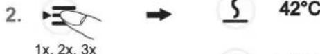
4.22 Keep-warm function
With the keep-warm function you can use one of the cooking zones to keep food warm. The respective cooking zone is operated at a low power level.
- Cookware is placed on a cooking zone and a power level (e.g. 3) is selected.
- By repeatedly pressing the Warming key select the setting:
corresponds to about 42^
corresponds to about 70^
corresponds to about 94^
- To switch off the function press the sensor fi eld on the far left or press the Warming key*
The keep-warm function is available for 120 minutes, after which the cooking zone will be switched off.

Modules (power management)
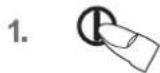
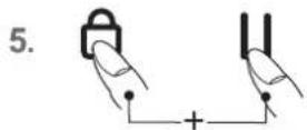
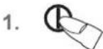
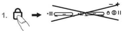
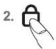
4.23 Locking
The lock can be used to lock key operation and cooking level settings. Only the ON/OFF key can be used to switch the hob off.
Activating the lock
- Press the lock key The control lamp above the Lock key will light up.
Switching off the lock
- Press the lock key . The control lamp above the Lock key will light up.
Notes
An activated lock will remain activated even if the hob is switched off. It must therefore be de-activated when cooking is re-commenced.
In the event of a power cut the lock will be cancelled, i.e. deactivated.
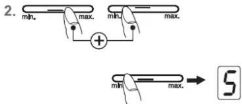
4.24 Power boost P
The power boost setting makes additional power available for induction cooking zones. A large quantity of water can be brought to the boil very quickly.
- Switch on the hob.
- Press the respective sensor fi eld on the far right on MAX of the respective cooking zone. The power setting display shows PThe power boost will now be activated.
- After 10 minutes the power boost setting will switch off automatically. The will go off and the power level will switch down to 9.
Please note:
Press the respective sensor fi eld to prematurely switch off the power boost setting.
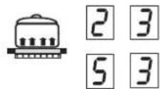
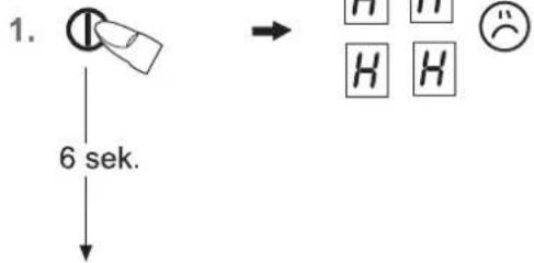
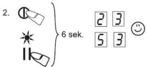
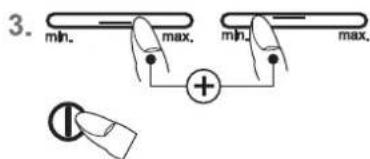
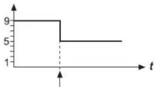
4.25 Power management
For technical reasons two cooking zones always comprise a module and have a maximum power level.
If this power range is exceeded when a higher power setting level or the power boost function is switched on the power management system will reduce the power setting of the corresponding cooking zone of the module.
The display for this cooking zone will initially blink, after which the highest-possible power setting will be consistently displayed.
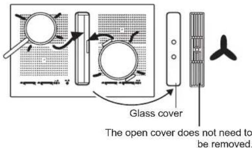

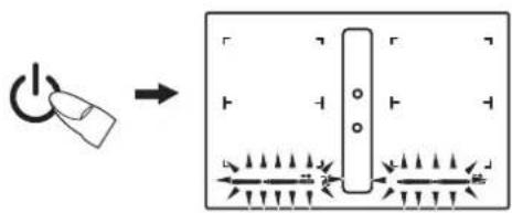
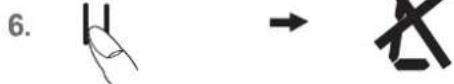
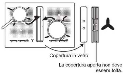
4.26 Using the fan
The fan is located in the middle of the hob with the extractor facing downwards.
Remove the glass cover before initial operation of the fan. The cover does not need to be removed from models with an open cover.
Important:
Do not put the cover onto the induction hob! Risk of burning!
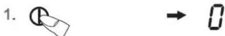
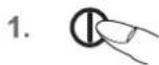
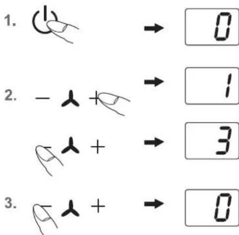
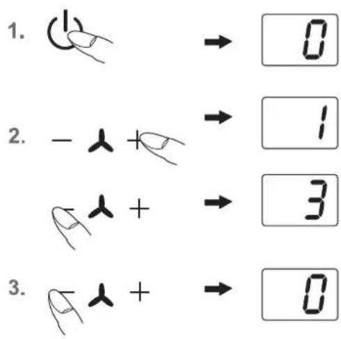
4.26.1 Switching the fan on and off
- Press the standby key (1) (approx. 1 s.).
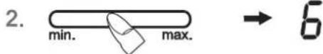
- Press the fan Plus key +1 s.). You will then be able to select a power setting, 1,2,3 or 4, by using the Plus +or Minus key . The symbol for the fan will light up. The intensive power setting 4 operates for 10 minutes, after which the power level is automatically reduced to power setting 3.
- Press the fan Minus key until 0 is shown in order to switch fan off.
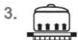
Hint
In order to ensure that extraction functions well with tall cooking pots (e.g. pots used for cooking asparagus), you can place a wooden spoon under the lid of the pot.
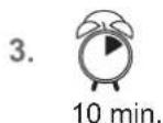
4.26.2 Fan time lag
The fan time lag is used after cooker in order to remove cooking odours. The filter is also dried in the fan.
- Press simultaneously the fan Plus key and Minus key . The fan time lag of 10 minutes will be activated. The symbol for the fan time lag will light up min.
- Pressing simultaneously again the Plus- and Minus key will set 60 minutes.
- The time lag function is deactivated by pressing the two keys simultaneously again.
The fan setting can be freely adjusted or changed when the fan time lag is switched on.
4.26.3 Stop delay time
The fan motor should continue operating for another 10-20 minutes every time the hob has been used for cooking. When the fan is switched off after having been in operation for at least 15 minutes, an automatic time lag at a low setting will follow for around 15 minutes.
This guarantees optimal functioning and the removal of remaining cooking steam.
When using a recirculating air filter, please always allow for a stop delay time of 10 - 60 minutes in order to optimally remove cooking odours.
When the fan is switched on again, in rare cases the odour molecules present in the fi liter may be combined with steam so that they are detected again. These remaining odours will disappear when the fan continues to operate.
Important
When the convection air mode is in operation, ventilation must be sufficient in order for the air humidity to be removed.
5 Cleaning and care
- Switch the hob off and let it cool down before you clean it.
- Never clean the glass ceramic hob with a steam cleaner or similar appliance!
- When cleaning make sure that you only wipe lightly over the ON/OFF key. The hob may otherwise be accidentally switched on!
5.1 Glass ceramic hob
Important! Never use aggressive cleaning agents such as rough scouring agent, abrasive saucepan cleaners, rust and stain removers etc.
Cleaning after use
- Always clean the entire hob when it has become soiled. It is recommended that you do so every time the hob is used. Use a damp cloth and a little washing up liquid for cleaning. Then dry the hob with a clean dry cloth to ensure that there is no detergent left on the surface of the hob.
Weekly cleaning
- Clean the entire hob thoroughly once a week with commercial glass ceramic cleaning agents. Please follow the manufacturer's instructions carefully. When applied, the cleaning agent will coat the hob in a protective fi lm which is resistant to water and dirt. All the dirt will remain on the fi lm and can then easily be removed. Then rub the hob dry with a clean cloth. Make sure that no cleaning agent remains on the surface of the hob since this will react aggressively when the hob is heated up and will change the surface.
5.2 Specific soiling
Heavy soiling and stains (limescaling and shiny, mo
ther-of-pearl-type stains) can best be removed when the hob is still slightly warm. Use commercial cleaning agents to clean the hob. Proceed as outlined under Item 2.
First soak food which has boiled over with a wet cloth and then remove remaining soiling with a special glass
scraper for glass ceramic hobs. Then clean the hob again as described under Item 2.
Burnt sugar and melted plastic must be removed immediately, when they are still hot, with a glass scraper. Then clean the hob again as described under Item 2.
Grains of sand which may get onto the hob when you peel potatoes or clean lettuce may scratch the surface of the hob when you move pots around. Make sure that no grains of sand are left on the hob.
Changes in the colour of the hob will not affect the function and the stability of the glass ceramic material. These colour changes are not changes in the material but food residues which were not removed and which have burnt into the surface.
Shiny spots result when the base of the cookware rubs on the surface of the hob, particularly when cookware with an aluminium base or unsuitable cleaning agents are used. They are difficult to remove with standard cleaning
agents. You may need to repeat the cleaning process several times. In time, the decoration will wear off and dark stains will appear as a result of using aggressive cleaning agents and faulty pan bases.
5.3 Hob fan
Cleaning the metal grease fi Iters
Clean the metal grease filters in the dishwasher or in mild soapy water at least once a month or in the event of excessive grease deposits and/or intensive use.
To remove the fi liter, lift up the fan cover and lift the U-shaped stainless steel ventilation plate in the suction intake opening upwards to remove it from the fan. Now remove the fi liter. To do so, press the lock in the recessed handle downwards and remove the fi liter.
The fi liter can be rinsed in a dishwasher. Stand the fi liter upright in the dishwasher. Please use only rinse aid that is suitable for use with aluminium in order to avoid damaging and discolouring the fi lters.
Never rinse right next to glasses or light-coloured porcelain.
Do not operate the fan without grease fi iters!
After rinsing the filiter, dry it and replace it in the fan. Please make sure that the recessed handle is visible after you have replaced the filiter. If possible, wipe the easily accessible inside of the fan with a cloth dampened with detergent every time you replace a filter, while at the same time paying attention to protruding parts in the inside of the fan.
Fan cleaning and care
The fan is best cleaned every time you clean the fi iters.
Condensation water may collect under the fiiter after water has boiled rapidly with the lid of the pot removed. This is quite normal. The water should, however, be removed and the inside of the fan cleaned.
The ventilation openings in the cover ensure that residual moisture resulting from cooking and cleaning can escape if necessary when the fan is not in operation and the cover is on.
Please clean the fi tter and the inside of the fan if unpleasant remaining odours escape.
The fan is best cleaned with a soft damp cloth and mild soapy water.
Service
The fi ler must remain accessible. Replace the charcoal fi ler mats of a charcoal fi ler every 5 to 24 months.
Replace the charcoal filter mats of plasma filters at least every 5 years. To do so, open the cover of the casing and replace the charcoal filter mats.
5.4 Energy saving tips
Switch ON the hood at minimum speed when you start cooking and kept it running for few minutes after cooking is fi nished. Increase the speed only in case of large amount of smoke and vapour and use boost speed(s) only in extreme situations.
Replace the charcoal fil ter(s) when necessary to maintain a good odour reduction effi ciency. Clean the grease fil ter(s) when necessary to maintain a good grease fil ter effi ciency
6 What to do if trouble occurs?
Interference with and repairs to the appliance by unqualified persons are dangerous as they can result in an electric shock or a short circuit. Do not interfere with or try to repair the appliance; this could cause injury to persons and damage to the appliance. Always have such work done by an expert, e.g. a Customer Service technician.
Please note
If your appliance is faulty, please check whether you can rectify the problem yourself by consulting these instructions for use.
You may be able to rectify some problems yourself. They are described below.
The fuses blow regularly?
Contact a technical customer service or an electrician!
You can't switch your induction hob on?
- Has the wiring system (fuse box) in the house blown a fuse?
- Has the hob been connected to the mains?
Is the control panel lock activated, i.e. does the display show an "L"? - Are the sensor keys partly covered by a damp cloth, fluid or a metallic object? Please rectify.
- Are you using unsuitable cookware? See the section on Cookware for induction hobs.
The symbol will blink and a time-limited continuous signal will sound.
Food which has boiled over, cookware or other items are causing the touch control sensor keys to be consistently operated.
Remedy: clean the surface or remove the item. To delete the symbol press the same key or switch the hob off and on.
Error code E2 is indicated?
The electronic unit is too hot. Check the installation of the hob. Make sure that there is sufficient ventilation.
See the section on "Protection against overheating". See the section on "Ventilation".
Error code E8 is indicated?
Fault on the left or right fan. The suction opening is blocked or covered or the fan is defect.
Check the installation of the hob. Make sure that there is sufficient ventilation.
See the section on "Protection against overheating". See the section on "Ventilation".
Error code U400 is indicated?
The hob has been incorrectly connected. The controls will switch off after 1s and a continuous signal will sound. Connect the appliance to the appropriate power supply.
An error code (ERxx or Ex) is indicated?
The appliance has developed a technical defect. Please call Customer Service.
The pot sign appears?
A cooking zone has been switched on and the hob is expecting a suitable pot or pan to be placed on the cooking zone (pan recognition). Only when a pot has been placed on the cooking zone will power be supplied.
The pot sign still appears, even though a pot or pan was placed on the hob?
The cookware is unsuitable for induction cooking or the pot or pan is too small.
Is the cookware you are using making noises?
This is due to technical reasons; the induction hob and the pot are not at risk.
Does the cooling fan still operate after it has been switched off?
This is normal since the electronic unit is being cooled down.
Is the hob making noises (clicking or cracking sounds)?
This is for technical reasons and cannot be avoided.
Does the hob have tears or cracks?
There is a risk of electric shocks if the glass ceramic hob develops fractures, cracks, tears or damage of any other kind. Immediately switch off the appliance. Disconnect the fuse immediately and call Customer Service.
7 Customer Service
Before you phone Customer Service:
- Try to rectify the problem yourself (see "What to do if trouble occurs?").
- Switch your appliance off and on again to find out whether the problem occurs again.
Please phone Customer Service if the problem continues or occurs again after you have carried out the checks described above.
Always state the following:
- Short type of fault/fault description
- Appliance and model number
Service number (i.e. the number following the word SERVICE on the nameplate) on the bottom of the hob or on the sheet with the product specifi cation.
The service number is also shown on the warranty certifi cate.
- Your full address and telephone number, including your area code

Table des matieres
Module (Powermanagement)
4.23 Verrouillage
4.25 Powermanagement
A Anything's done.
A thing's done.
A thing's done.
A thing's done.

Modules (powermanagement)