CPX958W - Projector HITACHI - Free user manual and instructions
Find the device manual for free CPX958W HITACHI in PDF.
User questions about CPX958W HITACHI
0 question about this device. Answer the ones you know or ask your own.
Ask a new question about this device
Download the instructions for your Projector in PDF format for free! Find your manual CPX958W - HITACHI and take your electronic device back in hand. On this page are published all the documents necessary for the use of your device. CPX958W by HITACHI.
USER MANUAL CPX958W HITACHI
Thank you for purchasing the Hitachi liquid crystal projector. Please read this user's manual thoroughly to ensure correct usage through understanding. After reading, store this instruction manual in a safe place for future reference.
natural_image
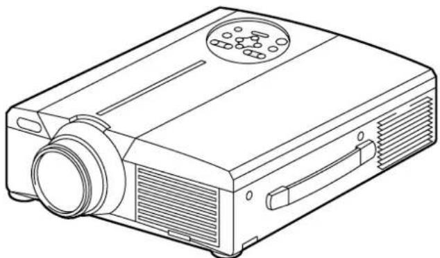
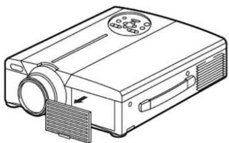
Line drawing of a projector with ventilation slots and a circular vent (no text or symbols)Outline
This liquid crystal projector is used to project various computer signals as well as NTSC/PAL/SECAM video signals onto a screen. Little space is required for installation and large images can easily be realized.
Features
(1) Outstanding brightness
The UHB lamp and high-efficiency optical system assure a high level of brightness.
(2) Partial magnification function
Interesting parts of images can be magnified for closer viewing.
(3) Distortion correction function
Distortion-free images are quickly available.
(4) Power zoom and power focus.
(5) P in P function
(6) USB jack
Contents Page
Before Use 3
Checking the package Contents 8
Names and functions of each part 8
Installation 12
Basic operations ......13
Adjustments and functions ......17
Connection to the video signal terminals 22
Connection to the RGB signal terminal 22
Connecting to the USB 25
Connection to the CONTROL signal terminal 26
Example of system setup 31
Cleaning the air filter 31
Lamp 32
Message table 32
When you think something wrong……33
Specifications 34
About the warranty and after-service 35

About Trademarks
• VGA and XGA are trademarks of IBM (International Business Machines Corporation).
• Macintosh is a registered trademark of Apple Computer Corporation of the U.S.
- VESA and SVGA are trademarks or registered trademarks of Video Electronics Standards association.
- Windows95 and Windows98 are registered trademarks of Microsoft Corporation in the U.S. and other countries. Carefully observe the trademarks and registered trademarks of all companies, even when not mentioned.

FOR THE CUSTOMERS IN U.K
THIS PRODUCT IS SUPPLIED WITH A TWO PIN MAINS PLUG FOR USE IN MAINLAND EUROPE. FOR THE U.K PLEASE REFER TO THE NOTES ON THIS PAGE.
IMPORTANT FOR UNITED KINGDOM
WORDING FOR CLASS I EQUIPMENT INSTRUCTION BOOKS AND LABELS
The mains lead on this equipment is supplied with a moulded plug incorporating a fuse, the value of which is indicated on the pin face of the plug. Shoud the fuse need to be replaced, an ASTA or BSI approved BS 1362 fuse must be used of the same rating. If the fuse cover is detachable never use the plug with the cover omitted. If a replacement fuse cover is required, ensure it is of the same colour as that visible on the pin face of the plug. Fuse covers are available from your dealer.
DO NOT cut off the mains plug from this equipment. If the plug fitted is not suitable for the power points in your home or the cable is too short to reach a power point, then obtain an appropriate safety approved extension lead or consult your dealer.
Shoud it be necessary to change the mains plugs, this must be carried out by a competent person, preferable a qualified electrician.
If there is no alternative to cutting off the mains plug, ensure that you dispose of it immediately, having first removed the fuse, to avoid a possible shock hazard by inadvertent connection to the mains supply.
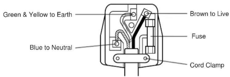
WARNING: THIS EQUIPMENT MUST BE EARTHED IMPORTANT:
The wires in the mains lead are coloured in accordance with the following code:
Green and Yellow = Earth, Blue = Neutral, Brown = Live.
text_image
Green & Yellow to Earth Blue to Neutral Brown to Live Fuse Cord ClampAs these colours may not correspond with the coloured makings identifying the terminals in your plug, proceed as follows:
The wire which is coloured Green and Yellow must be connected to the terminal in the plug which is marked with the letter E or by the earth symbol ① or coloured Green or Green and Yellow.
The wire coloured Blue must be connected to the terminal marked with the letter N or coloured BLUE or BLACK. The wire coloured BROWN must be connected to the terminal marked with the letter L or coloured BROWN or RED.
WARNING: This equipment has been tested and found to comply with the limits for a Class A digital device, pursuant to Part 15 of the FCC Rules. These limits are designed to provide reasonable protection against harmful interference when the equipment is operated in a commercial environment. This equipment generates, uses, and can radiate radio frequency energy and, if not installed and used in accordance with the instruction manual, may cause harmful interference to radio communications, Operation of this equipment in a residential area is likely to cause harmful interference in which case the user will be required to correct the interference at his own expense.
Instructions to Users:
This equipment complies with the requirements of FCC (Federal Communication Commission) Class A equipments provided that following conditions are met.
(1) Video signal cables:
Double shielded coaxial cables (so called FCC shield cable) must be used and the outer shield must be connected to the ground. Or, if normal coaxial cables are used, the cables must be enclosed in metal pipes or similar way to reduce the interference noise radiation.
(2) Power cord:
Shielded power cord must be used. The outer shield must be connected to the ground.
(3) Video inputs:
The input signal amplitude must no exceed the specified level.
Before Use
About the Symbols Various symbols are used in this instruction manual and on the product itself to ensure correct usage, to prevent danger to the user and others, and to prevent property damage. The meanings of these symbols are described below. It is important that you read these descriptions thoroughly and fully understand the contents.

Warning
This symbol indicates information that, if ignored, could possibly result in personal injury or even death due to incorrect handling.

Caution
This symbol indicates information that, if ignored, could result possibly in personal injury or physical damage due to incorrect handling.
Typical Symbols
This symbol indicates an additional warning (including cautions). An illustration is provided to clarify the contents (the illustration to the left indicates danger of electrical shock).

This symbol indicates a prohibited action. The contents will be clearly indicated in an illustration or nearby (the symbol to the left indicates that disassembly is prohibited).

This symbol indicates a compulsory action. The contents will be clearly indicated in an illustration or nearby (the symbol to the left indicates that the power plug should be disconnected from the power outlet).

Warning
■ If a problem should occur.
- If smoke or a strange odor arise, continued use could result in fire or electrical shock. In such case, immediately turn off the power switch and then disconnect the power plug from the power outlet. After making sure that the smoke or odor has stopped, contact your dealer for repairs. Never attempt to make repairs yourself because this is dangerous.
- Do not use this projector if there is no image or sound, or if the sound is distorted. Continued use could result in fire or electrical shock.


Disconnect the plug from the power outlet.
In such case, immediately turn off the power switch, disconnect the power plug from the power outlet and contact your dealer.
- If water should enter the inside of this projector, immediately turn off the power switch, disconnect the power plug from the power outlet and contact your dealer.
■ Do not install on an unstable surface.
- Do not install this projector on an unstable surface such as a wobbly stand or incline because this could result in the projector falling and causing injury.

■ Do not open the cabinet.
- Never open the cabinet. There is high voltage inside which can cause electrical shock.

Do not disassemble.
Electric shock hazard.
Contact your dealer for disassemb internal inspection, adjustment and repair.
■ Do not modify.
Do not modify this projector because this could result in fire or electrical shock.

Do not disassemble.
■ Do not use in the bathroom.
Do not use this projector in the bathroom because this could result in fire or electrical shock.

Do not use near water.
■ Do not insert foreign objects.
- Do not insert metal objects through the ventilation openings, etc., of this projector or drop such objects inside because this could result in fire or electrical shock.

- If a foreign object should enter this projector, immediately turn off the power switch, disconnect the power plug from the power outlet and contact your dealer.
Continued use could result in fire or electrical shock. Use special caution in households where children are present.
Disconnect the plug from the power outlet.
■ Do not look through the lens when the lamp is on.

Never look through the lens when the lamp is on. The powerful light could adversely affect vision. Use special caution in households where children are present.
■ Avoid shock or impact on the projector.
If the projector should fall, resulting in damage to the cabinet, immediately turn off the power switch, disconnect the power plug from the power outlet and contact your dealer. Continued use could result in fire or electrical shock.

Disconnect the plug from the power outlet.
■ Do not place this projector in a container containing liquid.

Do not place flower vases, flower pots, cups, cosmetics, liquids such as water, etc., on top of this projector. Spillage could result in fire or electrical shock.
■ Use only the indicated power supply.

Use only the indicated power supply. The use of any other power supply could result in fire or electrical shock.

Warning
■ Handle the power cord with care.
- Do not damage, cut, process or strongly twist the power cord. Placing heavy objects on the power cord, heating or strongly pulling the power cord can result in damage as well as fire or electrical shock.
- Pulling on the power cord
- Placing heavy objects on the power cord
- Damaging the cord
- Placing near heaters

- Do not position the power cord under the projector. This can damage the power cord and cause fire or electrical shock. Also, do not place a spread, cover, etc., over the power cord because this could result in the inadvertent placing of heavy objects on the concealed power cord.
- If the power cord is damaged (exposed or broken core wires, etc.), contact your dealer for replacement; otherwise, fire or electrical shock could result.
● Make sure there is no dust, etc., on the power plug and insert a knife blade to make sure that there is no looseness.

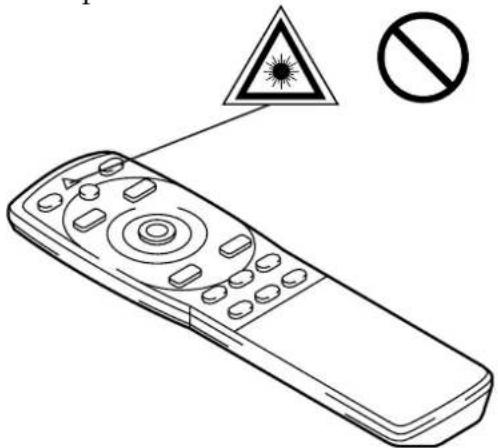
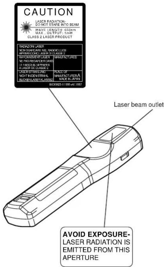
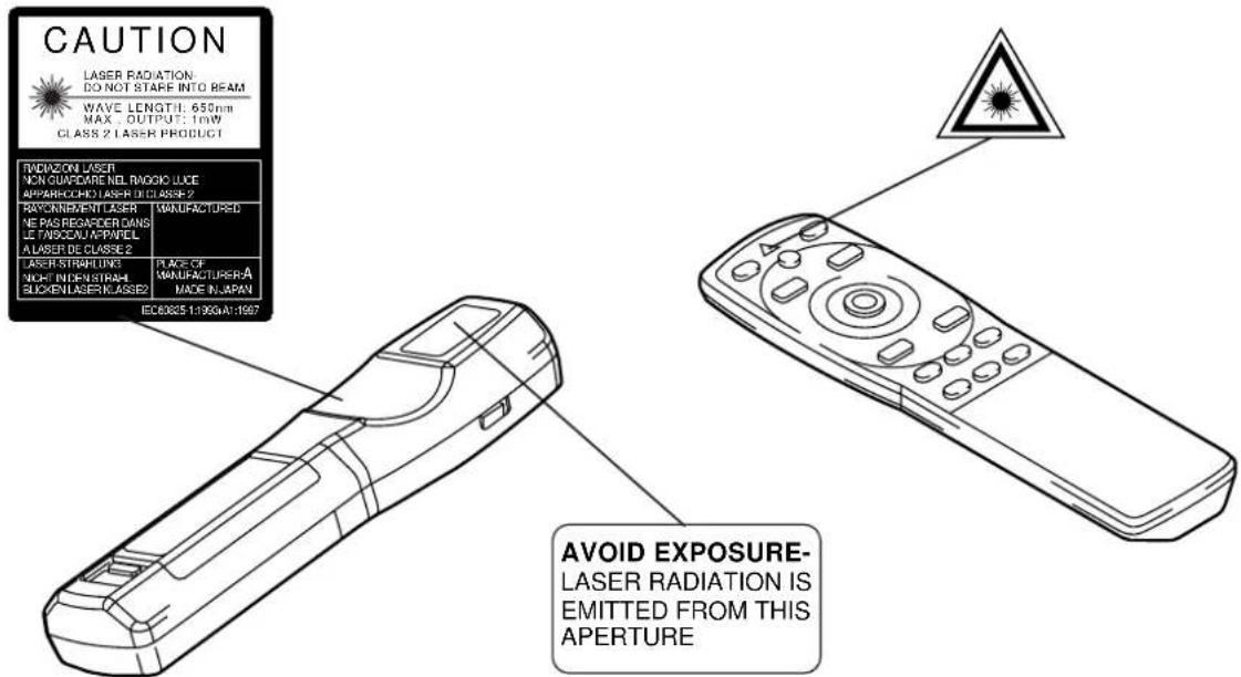
■ Do not allow the laser beam to enter the
eyes.
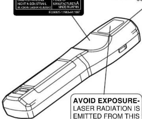
- This remote control is equipped with a laser pointer and a laser beam is emitted from the laser outlet. Do not look directly into the laser beam outlet or direct the laser beam at other people.
Vision can be impaired if the laser beam enters the eyes. Especially pay attention if children are present.
text_image
Diagram of a remote control with warning symbol and prohibition sign■ High temperatures are generated when the lamp is lit, so do not place objects in front of the lens.

text_image
CAUTION LASER RADIATION- DO NOT STARE INTO BEAM WAVE LENGTH: 650nm MAX . OUTPUT: 1mW CLASS 2 LASER PRODUCT RADIATION LASER NON-GARLICARE NEI RADGOLICE APPARECHOI LASER DI CLASS 2 RAYONREVENT LASER NE PAS REGARDER DANS LE FASSEAU APPAREL A LASER DE CLASSE 2 LASER STRATURS NIGHT INDEPENDENT EUXEVE LASER HD ASSE2 MANUFACTURED PLACE OF MANUFACTURER A MADE IN JAPAN ISO60825-1 1998 +A7 1997 Laser beam outlet AVOID EXPOSURE- LASER RADIATION IS EMITTED FROM THIS APERTURE
Caution
■ Do not sit or place heavy objects on this projector.
- Do not sit on this projector.
This could result in overturning, leading to damage or personal injury. Use special caution in households where children are present.

- Do not place heavy objects on this projector.
Placing heavy objects on this projector could result in loss of balance or falling and cause personal injury.
■ Do not block the ventilation openings. Do not block the ventilation openings of this projector. Blocking ventilation could lead to internal overheating which could result in
fire. Do not place this projector on its side during use or push it into a small, poorly ventilated location. Do not place this projector on a carpet or bedding or cover it with a table cloth,

etc. Also, when installing this projector, make sure the ventilation openings are at least 30cm from the wall.
■ Care and maintenance.
For safety purposes, disconnect the power plug from the power outlet before starting the care and maintenance of this projector.

Disconnect the plug from the power outlet.
■ Battery usage.
- Use only the specified batteries with this projector. Do not mix old and new batteries because this could result in fire or personal injury due to battery cracking or leakage.
- Make sure the plus and minus terminals are correctly aligned when loading the batteries.
Incorrect loading could result in personal injury or contamination of the surroundings due to battery cracking or leakage.
■ Clean the projector interior once every two years.
Request your dealer to clean the interior of the projector approximately every two years. Accumulations of dust inside the
projector can result in fire or malfunction if not cleaned for an extended period. This cleaning is more effective if performed before every humid periods such as rainy

season, etc. Ask your dealer for details about internal cleaning.
■ Avoid installation in humid or dusty locations.
- Do not install this projector in a humid or dusty location. This could result in fire or electrical shock.
- Avoid installation near the kitchen, a humidifier or other locations where there is oily smoke or humidity. This could result in fire or electrical shock.
■ Use the caster brakes.
When installing this projector on a stand with casters, use the caster brakes to prevent the stand moving or overturning and causing personal injury.

■ Do not handle the power cord roughly.
- Keep the power cord away from heaters because the heat could melt the power cord and cause fire or electrical shock.
- Do not touch the power plug with wet hands because this could result in electrical shock.

- When disconnecting the power plug, do not pull on the power cord. This could damage the power cord and cause fire or electrical shock. Always grip the plug when disconnecting.

Caution
■ When the projector is not to be used for an extended period.
For safety purposes when the projector is not to be used for an extended period because of travel, etc., always disconnect the power plug from the power outlet. Also close the lens cover to prevent the lens surface being scratched.

Disconnect the plug from the power outlet.
[General Cautions]
■ Avoid excessively hot locations.
Do not place this projector in direct sunlight or near a hot object such as a stove, etc., because the heat could have adverse influence on the cabinet and other parts.

■ Sound volume.
Set the volume at a suitable level to avoid bothering other people. It is also better to keep the volume level low and close the windows at night to protect the neighborhood environment.
■ Lens care
Use commercially available lens tissue to clean the lens (used to clean cameras, eyeglasses, etc.). Be careful not to scratch the lens with hard objects.

■ Moving the projector.
- When moving the projector, be sure to replace lens cap, disconnect the power plug from the power outlet and disconnect all external connections. Failure to do this could damage the power cord and cause fire or electrical shock.

Disconnect the plug from the power outlet.
Avoid any impact or shock to the projector because this could result in malfunction.
- When moving this projector outdoors, protect it from wetting due to rain, etc. If the projector should become wet, dry it thoroughly before further use. Continued use while wet could result in fire or electrical shock.

■ Cabinet care.
- The cabinet is made of plastic and discoloration or paint peeling can occur if wiped with a solvent such as benzine, thinner, etc.
- Before using chemical wipes, be sure to read and observe the instructions.
- Do not spray volatile substances such as insect repellent on the cabinet. Also, do not allow long-term close contact with rubber or vinyl products because this could result in discoloration, peeling paint, etc.
- Use a soft cloth to clean the cabinet and operation panel. When excessively soiled, dilute a neutral detergent in water, wet and wring out the cloth and afterward wipe with a dry cloth. Do not apply undiluted detergent directly to the projector.
■ Extended usage.
When using this projector for an extended period, stop periodically to rest the eyes to prevent eye fatigue.
Checking the package Contents
Make sure all of the following items are included in the package. If anything is missing, please contact your dealer.
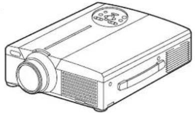
natural_image
Line drawing of a projector with ventilation slots and a circular vent (no text or symbols)Projector unit
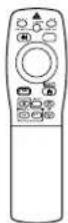
Remote control
Remote control
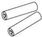
Batteries
text_image
HITACHI CD-X956W/E CD-X960W/E Lipidial Epoxyte Projetier magnosimo/Inse Progenarmal Projetier magnosimo/Inse Miogranular Composte Isped Inse 2017/2018 Prennis-1-concetar Injure ABOTC/INSE Prennis-2-pentia de 2017/2018 Inse 2017/2018 Vibenzammonium Projetier magnosimo/Inse Pyrene Imogen Projetier magnosimo/InseUser's Guide (this document)
CP-X958W
CP-X960W
Power Cord
110V-US
220-UK, Europe
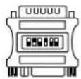
Mac adapter with dip switch
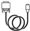
Mouse cable · 3
Names and functions of each part
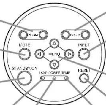
Main unit
ZOOM button
Used to adjust the size of the image. (Refer to page 13.)
MUTE button
This button turns the sound on and off. Press once to turn the sound off; then press again to turn the sound back on.
STANDBY / ON button
Press this button to turn the power on and off. When turned off, the projector enters standby status. Refer to page 13 - 14 for details.
LAMP indicator
Lights or flashes when the temperature inside the projector increases or the lamp does not light. Refer to page 33 for details.
POWER indicator
This indicator lights or blinks during standby and during operation. Refer to page 33 for details.
Remote control I/R receiver
Lens
Lens cap
text_image
ZOCM MUTE MENU INPUT STANDBY/ON LAMP POWER TEMP RESETFOCUS button
Used to adjust the focus of the image on the screen. (Refer to page 13.)
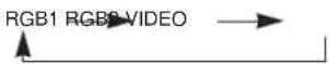
INPUT button
Press this button to switch the input. The input changes in the following sequence each time this button is pressed.
MENU button
Displays the image menu. Refer to page 17 - 21 for details.
RESET button
Used to reset the initial settings. Refer to page 10.17.25.26 for details.
TEMP indicator
Blinks when the fan malfunctions. Refer to page 33 for details.
natural_image
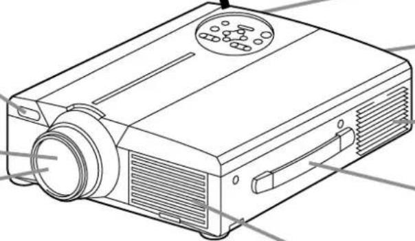
Line drawing of a projector with ventilation slots and a circular vent (no text or symbols)Speaker
Speaker
Cooling fan (exhaust side)
Carring handle
Cooling fan (intake side)
- Use the remote control in front of the remote control photoreceptor at a distance of about 5m or less and an angle of 30 degrees to the left or right of the center.
Names and functions of each part (continued)
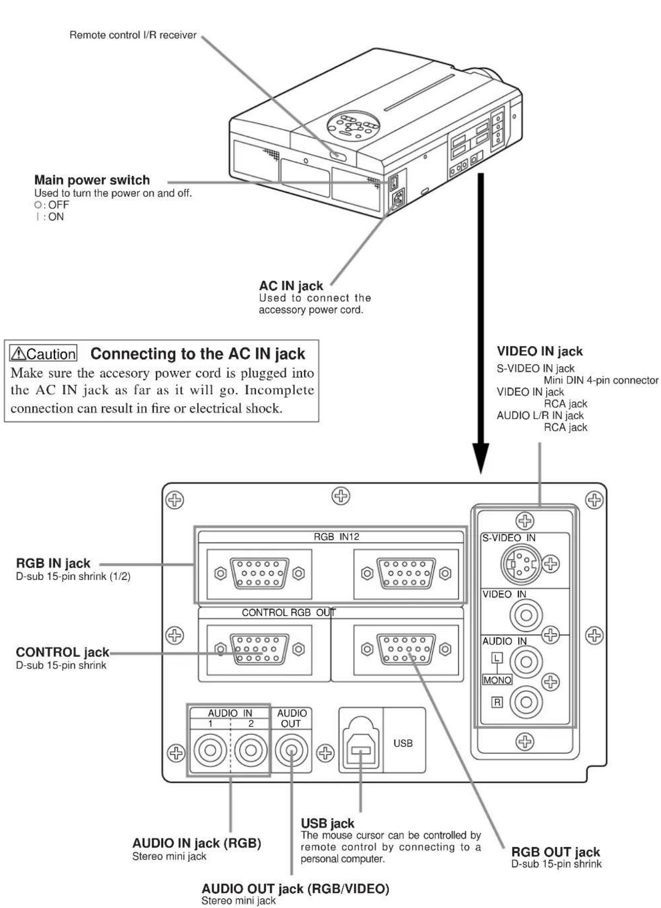
text_image
Remote control I/R receiver Main power switch Used to turn the power on and off. ○: OFF I : ON AC IN jack Used to connect the accessory power cord. Caution Connecting to the AC IN jack Make sure the accesory power cord is plugged into the AC IN jack as far as it will go. Incomplete connection can result in fire or electrical shock. VIDEO IN jack S-VIDEO IN jack Mini DIN 4-pin connector VIDEO IN jack RCA jack AUDIO L/R IN jack RCA jack RGB IN jack D-sub 15-pin shrink (1/2) CONTROL jack D-sub 15-pin shrink RGB IN12 CONTROL RGB OUT AUDIO IN 1 2 AUDIO OUT USB AUDIO IN jack (RGB) Stereo mini jack USB jack The mouse cursor can be controlled by remote control by connecting to a personal computer. AUDIO OUT jack (RGB/VIDEO) Stereo mini jack RGB OUT jack D-sub 15-pin shrinkNames and functions of each part (continued)
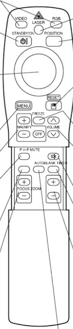
Remote control transmitter
VIDEO, RGB button
Press to switch the input. (Refer to page 13, 19.)
STANDBY / ON button
Used to turn the power on and off.
Press for 1 sec. or more to turn the power off (enter standby status).
(Refer to pages13 and 14.)
\* DISK PAD / MOUSE button \*4
(1) Used to select menu items when the menu screen is displayed (refer to page 16 - 18).
(2) When the menu is not displayed, the mouse shift function and left click function are active.
*1 (3) After the POSITION button has been pressed, the screen can be moved upward, downward and to the left and right.
\* MENU button
Used to turn the menu screen display on and off. (Refer to page 17 - 21.)
\* MAGNIFY button
Used to magnify the displayed image. (Refer to page 16.)
\* P in P button \*2
Used to turn P in P (Picture In Picture: displays sub video signal images in the RGB signal) on and off. Each time this button is pressed, operation will change in the following sequence:
(1) Reduce sub screen→(2) Magnify sub screen→(3)Off. (1) \~ (3)
(Refer to page 20.)
BLANK button
Used to turn blanking on and off. (Refer to page 20.)
FOCUS button
Used to adjust the focus of the image on the screen. (Refer to page 13.)
text_image
VIDEO LASER RGB STANDBYON POSITION MENU FREEZE MAGNIFY VOLUME OFF P in P MUTE AUTOBLANK TIMER FOCUS ZOOMLASER button
Turns the laser beam on and off. Refer to page 11 concerning usage and observe the cautions.
\* POSITION button
Press Position, then use the mouse Disk Pad to adjust the image position (RGB mode only). (Refer to page 16.)
\* RESET / MOUSE RIGHT button
(1) Operates as the RESET button when the menu is displayed. Press this button to return to the initial settings.
(2) Used to click the right mouse button when the menu is not displayed (refer to page 25,26).
*1 (3)Pressing this button after scrolling the screen with POSITION returns the screen to the original position.
\* FREEZE button
Used to turn the freeze (still) image display on and off. (Refer to page 15.)
VOLUME button
Adjusts the volume of the sound. Press [ ] to increase the volume and to decrease the volume. When there is no video signal input, operation is not possible when the input video signal is outside the sync range.
\* MUTE button
Applies Mute. (Press the Play button again to cancel.)
TIMER button
Turns the display of the time set with the Timer on the Menu screen on and off. The timer is not displayed when no input signal is detected or when SYNC is out of range or during blanking or during freezing. Refer to page 21 concerning the method used to set the timer.
ZOOM button
Used to adjust the size of the image. (Refer to page 13.)
\* AUTO button
Used to execute auto-adjust.*3
*These functions do not operate when initial screen message "NO INPUT IS DETECTED" or "SYNC IS OUT OF RANGE" is displayed.
\*1 POSITION icon
When the POSITION button is pressed, the moving display icon will appear at the bottom right of the screen.
While displaying the icon, you can operate POSITION.
\*2 P in P function
With the P in P function, signals are input to both RGB and VIDEO. This function operates only when the RGB signal has been selected. There is no display in the case of the no signal and when the RGB signal is outside the sync range.
When P in P is used, audio is automatically switched to video.
In P in P, audio input can be switched by pressing the VOL ∧ and VOL ∨ keys of the remote control, displaying the audio bar and moving DISK PAD left and right during the display.
\*3 Auto adjustment function
The projector automatically adjusts 4 items (V. POSIT, H. POSIT, H. PHASE, H. SIZE).
When you choose AUTO (move the cursor to the right from the manual operation position), the AUTO confirmation menu shown below is indicated.
\*4 Disk Pad method of operation
- Move and select by tilting Disk Pad in the required direction.
- Press Disk Pad in to realize the function of the mouse left button.
- A mouse cable is necessary if a mouse is to be used. (Refer to pages 26, 27.)
Names and functions of each part (continued)
Caution
• Auto adjust can take up to 30 seconds.
- Auto adjust may not operate correctly in some cases, depending on the computer connected and the signal.
- Be sure to expand images to full screen size when displaying low resolution images.
• After auto adjust, the image may be slightly dark in some cases due to automatic adjustment of the signal level. - Auto adjust can not execute when the initial display is "NO INPUT IS DETECTED" or "SYNC IS OUT OF RANGE" during FREEZE or MAGNIFY.
-
Auto Adjust is executed when the following operations are performed.
-
When the type of input source signal is changed.
- When the Auto Adjust (AUTO) button is pressed.
- The message AUTO IN PROGRESS will be displayed on the screen during automatic adjustment.
• The screen may be disrupted during automatic adjustment but this is not a malfunction. - RGB1 or RGB2 only can be used as the input signal.
- Auto Adjust can also be executed using the operation buttons of the main unit. Hold down the RESET button and press the input switch (INPUT) button.
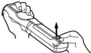
Loading the batteries Loading AA batteries into the remote control.

Remove the battery
cover.
Push the knob while lifting up the battery cover.
natural_image
Line drawing of a hand holding a tool or device with an arrow indicating direction (no text or symbols present)
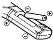
Loading the batteries.
Make sure the plus and minus poles are correctly oriented.

Close the battery cover.

Caution
Battery usage cautions
- Use only the specified batteries with this projector. Also, do not mix new and old batteries. This could cause in battery cracking or leakage, which could result in fire or personal injury.
- When loading the batteries, make sure the plus and minus poles are correctly oriented as indicated in the projector. Incorrect orientation could cause battery cracking or leakage, which could result in personal injury or pollution of the surrounding environment.
Caution
Remote control usage cautions
- Do not drop the remote control or apply impact.
- Do not wet the remote control or place it on any wet object. Such actions could result in malfunction.
- When not to be used for an extended period, remove the batteries from the remote control.
- Replace the batteries when remote control operation becomes difficult.
- Do not place the remote control close to the cooling fan of the projector.
- Do not disassemble the remote control in case of malfunction. please bring it to the service station.

Warning
The laser pointer of the remote control is used as a pointer.
Never look directly into the laser beam outlet or point the laser beam at other people.
The laser beam can cause vision problems.
text_image
CAUTION LASER RADIATION- DO NOT STARE INTO BEAM WAVE LENGTH: 650nm MAX. OUTPUT: 10kV CLASS 2 LASER PRODUCT RADIATION LASER NON GUARDWARE NEL RINGIO LUXE APPEARHOCH LASER D'CLASSE 2 RAYCINNEMENT LASER NE PAS REGARDER DANS LE FANSICAN APPAREL AL ASPER D'CLASSE 2 LASER STRAPTURE NICH INDEN STRAH BUCKEN LASER CLASSE 2 MANUFACTURED PLACE OF MANUFACTURERÄ MADE IN JAPAN IEC80825 1:1994/A1:1997 AVOID EXPOSURE- LASER RADIATION IS EMITTED FROM THIS APERTURETypical LCD Projector and Screen Installation
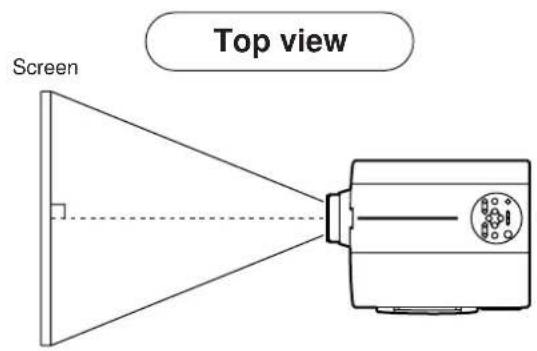
Use the diagram below as reference to determine the screen size and projection distance.
text_image
Screen Top view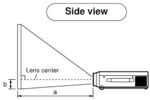
text_image
Side view Lens center b a| Screen size (inches) | a (inches) | b (inches) | |
| Minimum | Maximum | ||
| 40 55 73 1 | |||
| 60 85 114 2 | |||
| 80 114 151 2 | |||
| 100 144 191 3 | |||
| 120 176 231 3 | |||
| 150 220 282 4 | |||
| 200 291 386 6 | |||
a. Distance from the LCD projector to the screen
b. Distance from the lens center to the bottom of the screen (a,b: +/-10%).
Caution
The LCD projector should normally be used level (the legs can point upward).
Positioning the projector sideways, or with the lens pointing upward or downward can cause the internal temperature to rise, which could result in a malfunction.
The projection distances shown in the diagram to the left are for full size (1,024 x 768 dots).
Using the adjusters
Use the adjusters on the bottom to adjust the projection angle.
text_image
Front view Adjuster Side view Variable within the range of approximately 0° - 9°- Lift up the projector and release the adjuster lock.
- After adjusting the projection angle, firmly lock the adjusters.
- Rotate the adjusters for fine adjustment.
Caution
- Do not release the locks unless the projector is being held; otherwise, the projector could overturn or the fingers could get caught and cause personal injury.
- Do not force the adjusters to rotate. This could damage the adjusters or cause the lock to fail.
- Lock the adjusters firmly. If the lock is difficult to operate, change the angle slightly and try again.
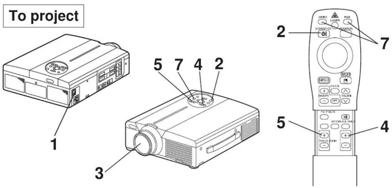
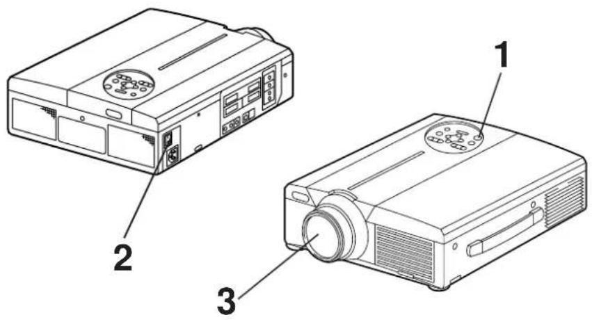
Basic operations
text_image
To project 1 2 3 4 5 7 2 5 4 VIDEO LASER RGB STANDARD POSITION REELED MENU FULLS MAGIFY VOLUME OFF PRE-PALATE AUTO-CRACK TIME POCUS ZOOM1 Turn on the main power switch of the projector [ I: ON].
• The Power indicator lights orange.
2 Press the STANDBY / ON button.
- The Power indicator will blink green and then light green. - The green blinking indicates warmup.
3 Remove the lens cap.
4 Use the ZOOM button to adjust the screen size.
5 Use the FOCUS button to adjust the focus.
(1) The display shown to the right will appear when the FOCUS button is pressed.
(2) Use the FOCUS button to adjust the focus until the image is sharp.
(3) The message "Focus" will disappear if any other button is pressed.
- (When there is no input signal, the Focus characters are not displayed when the input signal is outside the sync range.)
+++FOCUS+++
6 Turn on the power to the connected equipment.
Refer to page 31 concerning the connection of other equipment.
7 Press either the INPUT button of the projector or the VIDEO/RGB button of the remote control to select the signal to be projected on the screen.
Example on-screen display
RGB 1
The selected signal input channel will be displayed in the lower right part of the screen.
Basic operations (continued)
Turning off the power
text_image
Technical diagram of a projector with labeled parts including front, top, and side views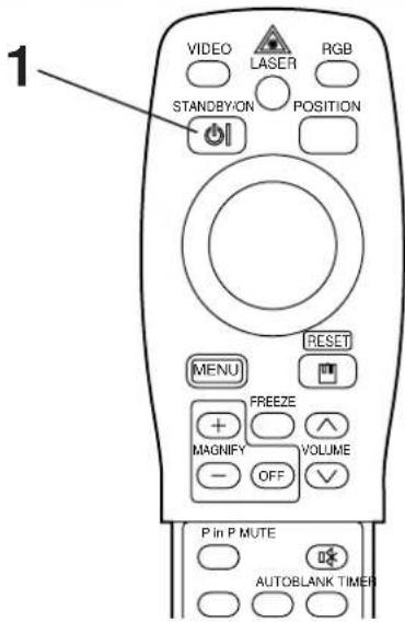
text_image
1 VIDEO LASER RGB STANDBY/ON POSITION MENU RESET FREEZE MAGNIFY VOLUME OFF P in P MUTE AUTOBLANK TIMER1 Press the STANDBY/ON button for approximately 1 sec.
- The Power indicator will blink orange, then the lamp will turn off. Approximately 1 sec. after that, the indicator will light orange.
- After the power is turned off, the lamp will be cooled for approximately 1 min. and the power cannot be turned off even by pressing the STANDBY/ON button.
- The standby status will not be entered if the time which the STANDBY/ON button is pressed is too short.
2 Turn off the main power switch of the projector [○ : OFF].
3 Attach the lens cap.
Caution
The fan will continue running for approximately 1 min. after the STANDBY/ON button is pressed. Do not turn off the main power switch while the lamp is on because this will shorten the service life of the lamp.
Plug & Play
This projector is VESA DDC 1/2B compatible. Plug & play is possible by connecting to a computer that is VESA DDC (Display Data Channel) compatible.
(Plug & play is a system configured with peripheral equipment including a computer and display, and an operating system.
Caution
- Use the RGB cable included with this projector when using plug & play. With other cables, pins (12) - (15) are sometimes not connected (effective only for RGB1).
- This device is recognized as a plug-and-play monitor. Use the standard Windows95/98 display drivers.
- This function may not operate, depending on the personal computer used.
- When the DDC function does not operate on a personal computer running Windows95/98, select the display type from Screen Priority. It is recommended that Super VGA 1024 x 768 (60-75Hz) be selected as the display type.
The DDC function will not operate when connected to a Macintosh.
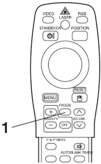
Freeze function
This function is used to freeze the image being displayed.
(refer to page 10)
text_image
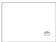
VIDEO LASER RGB STANDBY/ON POSITION MENU RESET FREEZE MAGN/FY VOLUME OFF P IN P MUTE AUTOBLANK TIMER 11 Press the FREEZE button.
- The image being displayed will freeze.
- The [ ] mark appears in the lower right corner of the screen when the Freeze function is on.
Cancelling the FREEZE function
1 Press the FREEZE button.
- The FREEZE function will be cancelled.
- The [▶] mark will be displayed for approximately 3 sec. when the FREEZE function is cancelled.
Caution
- When there is no input signal, the Freeze function is not effective when the input signal is outside the sync range.
- Pressing the FREEZE button alternately turns the freeze function on and off.
- The FREEZE function will be cancelled when the input select button is pressed or the display mode of the PC being used for display is changed.
- When a still image signal is input when the FREEZE function is on, make sure not to forget to cancel the FREEZE function.
- FREEZE function will be cancelled after the operations such as “FOCUS +, –”, “TIMER”, “P in P”, “AUTO”, “BLANK”, “VOLUME ∧ ∨”, “MENU”, “MUTE” and “POSITION”.
Basic operations (continued)
Magnify function
Part of an image can be displayed magnified.
(refer to page 10)
text_image
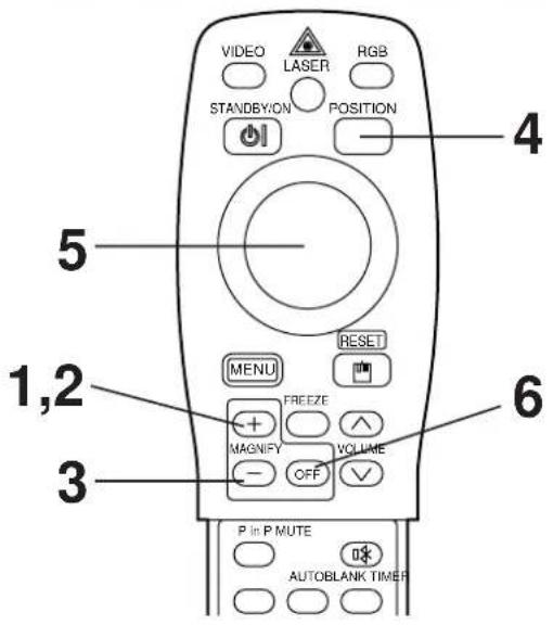
VIDEO LASER RGB STANDBYION POSITION - 4 5 1,2 3 RESET MENU FREEZE MAGNIFY VOLUME - OFF 6 P in P MUTE AUTOBLANK TIME1 Press the MAGNIFY + button.
- The center part of the image will be displayed magnified approximately 2x.
Changing the magnification ratio
2 Press the MAGNIFY + button.
- When this button is pressed, the image will be displayed even larger.
3 Press the MAGNIFY – button.
- When this button is pressed, the image will be displayed even smaller.
Moving the display area
4 Press the POSITION button.
5 Press the DISK PAD up, down, left and right buttons.
- The magnified area will move in accordance with the button pressed.
Returning to normal display
6 Press the MAGNIFY OFF button.
Caution
- When there is no video signal input, Magnify is not effective when the video signal input is outside the sync range.
- The magnify function will be cancelled when the input select button is pressed or the display mode of the PC being used for display is changed.
- The Magnify function will be cancelled after the operations such as "AUTO", "KEYSTONE".
Adjustments and functions
flowchart
graph TD
    A["1,2,3"] --> B["MENU"]
    C["1,3"] --> B
    D["1,2,3"] --> B
    E["1,3"] --> B
    F["1,2,3"] --> B
    G["1,3"] --> B
    H["1,2,3"] --> B
    I["1,3"] --> B
text_image
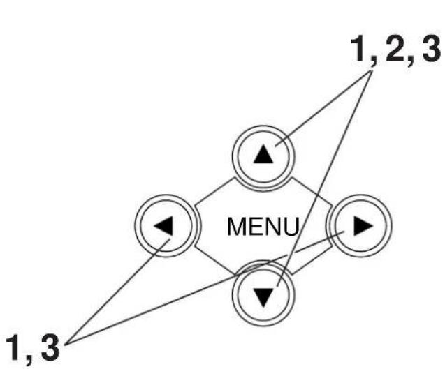
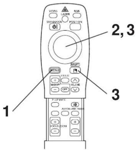
VIDEO LASER RGB STANDION POSITION MENU FREE MAGIP VOLUME OFF Pain/Punkte AUTOCOM/AMT TIMER FOCUS ZOOM 1 2,3 31 Press the MENU (▲▼◀▶) buttons of the projector or the MENU button of the remote control.
• The Menu screen will appear. (refer to page 18 - 21 for details.)
2 Press the MENU ( ▲▼◀▶ ) buttons of the projector or the DISK PAD button of the remote control to select the menu item to be adjusted. • The selected menu item will be displayed in orange.
3 Adjust the selected menu item with the MENU ( ▲▼◀▶ ) buttons of the projector or the DISK PAD button of the remote control.
- The selected menu item will be displayed in orange.
Returning to the initial settings
- Select the adjustment item to be returned to the initial settings.
- Press the RESET button.
Adjustments and functions (continued)
SET UP
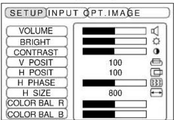
Images and display positions can be adjusted from the SETUP menu.
RGB signal input
text_image
SETUP INPUT OPT. IMAGE VOLUME BRIGHT CONTRAST V POSIT 100 H POSIT 100 H PHASE H SIZE 800 COLOR BAL R COLOR BAL BVideo signal input
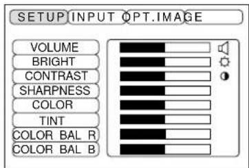
text_image
SETUP INPUT OPTIMAGE VOLUME BRIGHT CONTRAST SHARPNESS COLOR TINT COLOR BAL R COLOR BAL B| Adjustment item | Adjustment description |
| VOLUME | Volume decreases Volume increases |
| BRIGHT (BRIGHTNESS) | Darker Brighter |
| CONTRAST | Lower contrast Stronger contrast |
| SHARPNESS | Softer image Sharper image |
| COLOR | Less More ▶ |
| TINT | Redder Greener |
| V. POSIT (V. POSITION) | Moves the image up and down. |
| H. POSIT (H. POSITION) | Moves the image left and right. |
| H. PHASE | Eliminates blanking. |
| H. SIZE | Adjusts the horizontal size of the image. |
| COLOR BAL R (COLOR BALANCE Red) | Less red More ▶red |
| COLOR BAL B (COLOR BALANCE Blue) | Less blue More Blue |
Using the SETUP Menu
Move the cursor to the item to be adjusted and move the MENU button of the projector or the DISK PAD button of the remote control to change the length of the bar display.
Caution
- The menu cannot be displayed while the initial screen (“No input is detected.” or “Sync is out of range.”) is being displayed.
- Tint cannot be adjusted with N-PAL, M-PAL, PAL or SECAM video signal input.
- Tint, color and sharpness cannot be adjusted with RGB signal input.
• V. POSIT, H. POSIT, H. PHASE and H. SIZE cannot be adjusted with video signal input. - FREEZE function will be cancelled after the operation "Menu".
- Displaying the menu cancels freeze operations.
Adjustments and functions (continued)
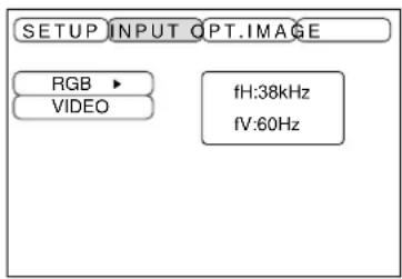
INPUT
The INPUT menu is used to select RGB signal sync signal frequency of the monitor and the VIDEO signal.
text_image
SETUP INPUT OPTIMAGE RGB VIDEO fH:38kHz fV:60Hz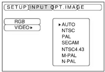
text_image
SETUP INPUT OPTIMAGE RGB VIDEO AUTO NTSC PAL SECAM NTSC4.43 M-PAL N-PAL| Adjustment item | Adjustment description |
| RGB | Displays the following RGB inputsfH: horizontal sync frequencyfV: vertical sync frequency |
| VIDEO | Sets the video signal system. When the screen is unstable (no color) or rolls, select the mode that matches the input signal. |
Adjustments and functions (continued)
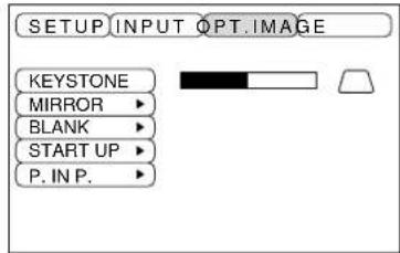
IMAGE
Projection image inversion, etc., can be selected from the IMAGE menu.
text_image
SETUP INPUT OPTIMAGE KEYSTONE MIRROR ▶ BLANK ▶ START UP ▶ P. IN P. ▶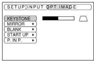
text_image
SETUP INPUT OPTIMAGE KEYSTONE MIRROR BLANK START UP P. IN P.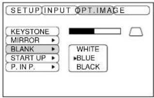
text_image
SETUP INPUT OPT. IMAGE KEYSTONE MIRROR ▶ BLANK ▶ START UP ▶ P. IN P. ▶ WHITE ▲BLUE BLACK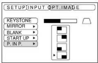
text_image
SETUP INPUT OPTIMAGE KEYSTONE MIRROR BLANK START UP P. IN P.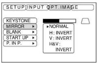
text_image
SETUP INPUT OPT IMAGE KEYSTONE MIRROR BLANK START UP P. IN P. NORMAL H: INVERT V: INVERT H&V: INVERT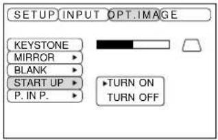
text_image
SETUP INPUT OPTIMAGE KEYSTONE MIRROR BLANK START UP P. IN P. TURN ON TURN OFF| Adjustment item | Adjustment description |
| KEYSTONE | Reduces keystone Reduces keystone distortion at the bottom distortion at the top |
| MIRROR | Sets vertical or horizontal inversion of the projected image.H: horizontal inversion onlyV: vertical inversion onlyH&V: both horizontal and vertical inversion. |
| BLANK | Sets the color to be used for blanking with BLANK ON or when there is no signal.Blanking is turned on, when there is no signal for approximately 5 min. |
| START UP | Opens and closes the initial settings screen during signal input at start up.When canceled, the background color will change to blue. |
| P in P | Selects the P in P sub screen display position. |
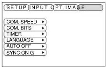
Adjustments and functions (continued)
OPT
Communication functions, etc., can be set from the OPT menu.
text_image
SETUP INPUT OPT.IMAGE COM. SPEED > COM. BITS > TIMER > LANGUAGE > AUTO OFF > SYNC ON G >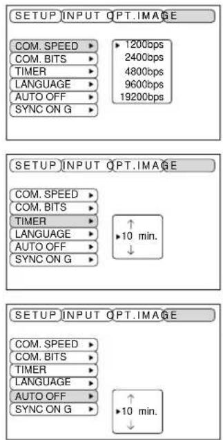
text_image
SETUP INPUT OPT.IMAGE COM. SPEED ▶ 1200bps COM. BITS ▶ 2400bps TIMER ▶ 4800bps LANGUAGE ▶ 9600bps AUTO OFF ▶ 19200bps SYNC ON G ▶ SETUP INPUT OPT.IMAGE COM. SPEED ▶ ↑ 10 min. COM. BITS ▶ TIMER ▶ LANGUAGE ▶ AUTO OFF ▶ SYNC ON G ▶ SETUP INPUT OPT.IMAGE COM. SPEED ▶ ↑ 10 min. COM. BITS ▶ TIMER ▶ LANGUAGE ▶ AUTO OFF ▶ SYNC ON G ▶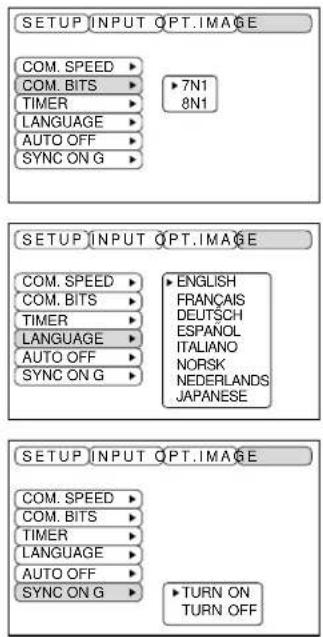
text_image
SETUP INPUT OPTIMAGE COM. SPEED ▶ 7N1 COM. BITS ▶ 8N1 TIMER ▶ LANGUAGE ▶ AUTO OFF ▶ SYNC ON G ▶ SETUP INPUT OPTIMAGE COM. SPEED ▶ ENGLISH COM. BITS ▶ FRANÇAIS TIMER ▶ DEUTSCH LANGUAGE ▶ ESPANOL AUTO OFF ▶ ITALIANO SYNC ON G ▶ NORSK NEDERLANDS JAPANESE SETUP INPUT OPTIMAGE COM. SPEED ▶ TURN ON COM. BITS ▶ TURN ON TIMER ▶ LANGUAGE ▶ AUTO OFF ▶ SYNC ON G ▶| Adjustment item | Adjustment description |
| COM. SPEED | Sets the communication speed (5 steps). |
| COM. BITS | Sets the bit configuration for the communication data.7N1...7 data bits, No parity, 1 stop bit.8N1...8 data bits, No parity, 1 stop bit. |
| TIMER | Sets the timer display time (0 - 99) min. |
| LANGUAGE | Selects the menu screen language(English, French, German, Spanish, Italian, Norwegian, Dutch, Japanese). |
| AUTO OFF | Sets the time after which the power will be turned off (standby status) when there is no input signal. The settings are 1 - 99 min, 0 and None. |
| SYNC ON G | Sets the SYNC ON G feature on/off. |
Connection to the video signal terminals
1. Input signals
| S-VIDEO signal | Brightness signal 1.0V p-p, 75 Ω terminatorColor signal 0.286V p-p (burst signal), 75 Ω terminator | |
| VIDEO signal | 1.0V p-p, 75 Ω terminator | |
| Audio signal | Input | 200mV rms, 20k Ω or less (max. 3.0V p-p) |
| Output | 0~200mVrms,1k Ω | |
2. Signal input jacks
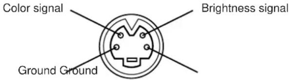
text_image
Color signal Brightness signal Ground GroundS-VIDEO input (mini DIN 4-pin)
Caution
The priority sequence of the video input jacks is as follows.
(1) S-VIDEO input jack (2) RCA jack input jack When video signals are being projected, the audio input by the video is output to the audio output jack (RGB/VIDEO).
Connection to the RGB signal terminal
1. Input signals
| Video signal Analog, 0.7V p-p, 75 Ω terminator (positive polarity) | |
| Horizontal sync signal TTL level (positive/negative polarity) | |
| Vertical sync signal TTL level (positive/negative polarity) | |
| Compound sync signal TTL level | |
| Audio signal | Input 200mV rms, 20k Ω or less (max. 3.0V p-p) |
| Output 0~200mVrms,1k Ω | |
2. Signal input jacks
| 1 Video input (red) 9 N.C | ||
| 2 Video input (green) 10 Ground | ||
| 3 Video input (blue) 11 N.C | ||
| 4 N.C 12 DDC jack (Display Data Channel) | ||
| 5 N.C 13 Horizontal sync signal/compound sync signal | ||
| 6 Ground (red) 14 Vertical sync signal | ||
| 7 Ground (green) 15 DDC jack (Display Data Channel) | ||
| 8 Ground (blue) |
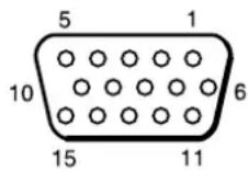
D-sub 15-pin shrink jack
3. Example of computer signal
| Resolution fH fV H · V (kHz) (Hz) | Rating Signal mode Display mode | Note 1 | ||||
| 640 · 400 24.8 | 56.4 NEC PC9800 | Zoom in | ||||
| 640 · 350 | 37.9 | 85.1 | VESA | VGA-1 | Zoom in | |
| 640 · 400 | 37.9 | 85.1 | VESA | VGA-2 | Zoom in | |
| 720 · 400 | 37.9 | 85.0 | VESA | TEXT | Zoom in | |
| 640 · 480 | 31.5 | 59.9 | VESA | VGA-3 | Zoom in | |
| 640 · 480 | 35.0 | 66.7 | Mac13"mode | Zoom in | SW 1 ON SW 2 ON | |
| 640 · 480 | 37.9 | 72.8 | VESA | VGA-3(72Hz) | Zoom in | |
| 640 · 480 | 37.5 | 75.0 | VESA | VGA-3(75Hz) | Zoom in | |
| 640 · 480 | 43.3 | 85.0 | VESA | VGA-3(85Hz) | Zoom in | |
| 800 · 600 | 35.2 | 56.3 | VESA | SVGA(56Hz) | Zoom in | |
| 800 · 600 | 37.9 | 60.3 | VESA | SVGA(60Hz) | Zoom in | |
| 800 · 600 | 48.1 | 72.2 | VESA | SVGA(72Hz) | Zoom in | |
| 800 · 600 | 46.9 | 75.0 | VESA | SVGA(75Hz) | Zoom in | |
| 800 · 600 | 53.7 | 85.1 | VESA | SVGA(85Hz) | Zoom in | |
| 832 · 624 | 49.7 | 74.5 | Mac16"mode | Zoom in | SW 2 ON SW 4 ON | |
| 1024 · 768 | 48.4 | 60.0 | VESA | XGA(60Hz) | ||
| 1024 · 768 | 56.5 | 70.1 | VESA | XGA(70Hz) | ||
| 1024 · 768 | 60.0 | 75.0 | VESA | XGA(75Hz) | ||
| 1152 · 864 | 67.5 | 75.0 | VESA | SXGA(75Hz) | Zoom out | |
| 1280 · 960 | 60.0 | 60.0 | VESA | SXGA(60Hz) | Zoom out | |
| 1280 · 1024 | 64.0 | 60.0 | VESA | SXGA(60Hz) | Zoom out | |
| 1280 · 1024 | 80.0 | 75.0 | VESA | SXGA(75Hz) | Zoom out | |
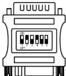
Note 1: Mac adapter is necessary to the resolution mode.
Projector is compatible with 13 inch mode and 16 inch mode.
Mac 13" mode=switch 1 and switch 2 are ON.
Mac 16" mode=switch 2 and switch 4 are ON.
text_image
ON 1 2 3 4 5 6 OFF(Example 16 inch mode)
Caution
- Some computers may have multiple display screen modes. Use of some of these modes will not be possible with this projector.
- Be sure to check jack type, signal level, timing and resolution before connecting this projector to a computer.
- Depending on the input signal, full-size display may not be possible in some cases.
Connection to the RGB signal terminal (continued)
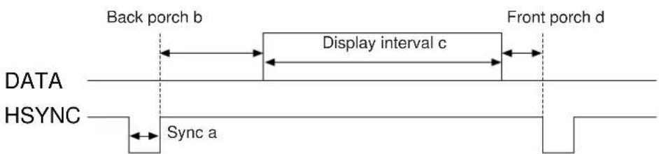
4. Initial set signals
The following signals are used for the initial settings.
The signal timing of some computer models may be different. In such case, refer to pages 17 and 18 and adjust the V.POSIT and H.POSIT of the menu.
text_image
Back porch b Front porch d Display interval c DATA HSYNC Sync a| Computer/Signal | Horizontal signal timing (μs) | |||
| a | b | c | d | |
| VGA-1(85Hz) 2.0 | 3.0 20.3 1.0 | |||
| VGA-2(85Hz) 2.0 | 3.0 20.3 1.0 | |||
| PC-9800 3.0 3.8 | 30.4 3.0 | |||
| TEXT 2.0 3.0 | 20.3 1.0 | |||
| VGA-3 3.8 1.9 | 25.4 0.6 | |||
| Mac 13"mode 2.1 | 3.2 21.2 2.1 | |||
| VGA-3(72Hz) 1.3 | 3.8 20.3 1.0 | |||
| VGA-3(75Hz) 2.0 | 3.8 20.3 0.5 | |||
| VGA-3(85Hz) 1.6 | 2.2 17.8 1.6 | |||
| SVGA(56Hz) 2.0 | 3.6 22.2 0.7 | |||
| SVGA(60Hz) 3.2 | 2.2 20.0 1.0 | |||
| Computer/Signal | Horizontal signal timing (μs) | |||
| a | b | c | d | |
| SVGA (72Hz) 2.4 | 1.3 16.0 1.1 | |||
| SVGA (75Hz) 1.6 | 3.2 16.2 0.3 | |||
| SVGA (85Hz) 1.1 | 2.7 14.2 0.6 | |||
| Mac 16"mode 1.1 | 3.9 14.5 0.6 | |||
| XGA (60Hz) 2.1 | 2.5 15.8 0.4 | |||
| XGA (70Hz) | 1.8 1.9 13.7 0.3 | |||
| XGA (75Hz) | 1.2 2.2 13.0 0.2 | |||
| SXGA (1152 X 864, 75Hz) | 1.2 2.4 10.7 0.6 | |||
| SXGA (1280 X 960, 60Hz) | 1.0 2.9 11.9 0.9 | |||
| SXGA (1280 X 1024, 60Hz) | 1.0 2.9 11.9 0.9 | |||
| SXGA (1280 X 1024, 75Hz) | 1.1 1.8 9.5 0.1 | |||
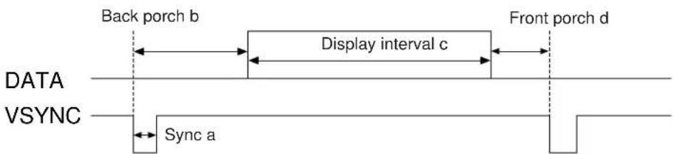
text_image
Back porch b Display interval c Front porch d DATA VSYNC Sync a| Computer/Signal | Vertical signal timimg (lines) | |||
| a | b | c | d | |
| VGA-1 (85Hz) | 3 60 | 350 32 | ||
| VGA-2 (85Hz) | 3 41 | 400 | 1 | |
| PC-9800 | 8 25 | 400 | 7 | |
| TEXT | 3 42 | 480 | 1 | |
| VGA-3 | 2 33 | 480 10 | ||
| Mac 13"mode | 3 39 | 480 | 3 | |
| VGA-3 (72Hz) | 3 28 | 480 | 9 | |
| VGA-3 (75Hz) | 3 16 | 480 | 1 | |
| VGA-3 (85Hz) | 3 25 | 480 | 1 | |
| SVGA (56Hz) | 2 22 | 600 | 1 | |
| SVGA (60Hz) | 4 23 | 600 | 1 | |
| Computer/Signal | Vertical signal timimg (lines) | |||
| a | b | c | d | |
| SVGA (72Hz) | 6 23 | 600 37 | ||
| SVGA (75Hz) | 3 21 | 600 | 1 | |
| SVGA (85Hz) | 3 27 | 600 | 1 | |
| Mac 16"mode | 3 39 | 624 | 1 | |
| XGA (60Hz) | 6 29 | 768 | 3 | |
| XGA (70Hz) | 6 29 | 768 | 3 | |
| XGA (75Hz) | 3 28 | 768 | 1 | |
| SXGA (1152 X 864, 75Hz) | 3 32 | 864 | 1 | |
| SXGA (1280 X 960, 60Hz) | 3 36 | 960 | 1 | |
| SXGA (1280 X 1024, 60Hz) | 3 38 | 1024 1 | ||
| SXGA (1280 X 1024, 75Hz) | 3 38 | 1024 1 | ||
- Connect the projector and computer with a suitable commercially available cable. Disconnect the mouse cable from the projector.
- Press the INPUT button of the projector or the RGB 1/2 button of the remote control and select the input where the computer is to be connected.
- Start the mouse function.
- Refer to page 10 concerning the remote control of mouse operations.
- Varying the force with which the DISK PAD button is pressed varies the speed of mouse operation.
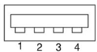
USB jack (B type)
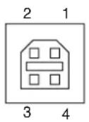
Projector
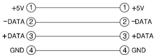
text_image
+5V ①—① +5V -DATA ②—② -DATA +DATA ③—③ +DATA GND ④—④ GNDUSB cable
Computer
USB jack (A type)
Caution
- Before making connections, read the instruction manual of the equipment to be connected.
- Use the optional USB cable to connect.
- Effective with USB only when the mouse is used.
- Do not use with any device other than a personal computer.
- When using with Windows 95, it is necessary to set so that USB can be used with version OSR 2.1 or higher. Depending on the kind or the vision of the host controller, operation may not be possible in some cases.
- In the case of notebook type computers with a built-in pointing device such as a track ball, in some cases the built-in pointing device will have priority even if a mouse is connected and the mouse may not be selected.
In such case, disable the built-in pointing device and change the BIOS setting (system setup) so that an external mouse can be selected.
After changing the BIOS setting, perform the operations described in 1 - 3 above.
Refer to the computer hardware manual concerning the BIOS setting.
Also, some computers may not have a utility program to operate a mouse. Refer to the computer hardware manual.
Connection to the control signal terminal
1. Mouse functions
(1) Turn off the main power switches of the projector and computer and connect the two units with the cable provided or an optional suitable commercially available cable. Disconnect the USB cable from the projector.
(2)Turn on the main switch of the projector (the POWER indicator lamp will light green).
(3) Press the INPUT button of the projector or the RGB button of the remote control and select the input where the computer is to be connected.
(4) Turn on the computer power supply.
(5) Start the mouse function.
If the mouse has not been started, reboot the computer (soft reboot or reboot buttons).
(6) Refer to page 10 concerning remote control operation.
(7) Varying the force with which the DISK PAD button is pressed varies the speed of mouse operation.
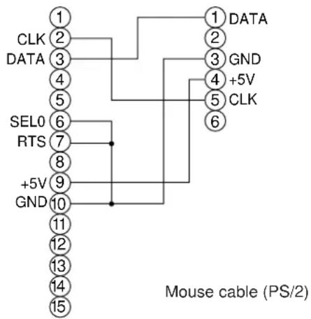
PS/2 Mouse
control jack D-sub 15-pin shrink jack
Projector Computer
flowchart
graph TD
    A["1"] --> B["CLK 2"]
    A --> C["DATA 3"]
    A --> D["4"]
    A --> E["5"]
    A --> F["6"]
    A --> G["7"]
    A --> H["8"]
    A --> I["9"]
    A --> J["GND 10"]
    A --> K["11"]
    A --> L["12"]
    A --> M["13"]
    A --> N["14"]
    A --> O["15"]
    P["1"] --> Q["DATA 2"]
    P --> R["GND 3"]
    P --> S["4 +5V"]
    P --> T["5 CLK"]
    P --> U["6"]
    V["SEL0"] --> W["6"]
    X["RTS"] --> Y["7"]
    Z["+5V"] --> AA["9"]
    AB["GND"] --> AC["10"]
    AD["Mouse cable (PS/2)"] --> AE["1"]
Mouse jack Mini
DIN 6-pin

Use the mouse cable provided or a PS/2 mouse cable (for IBM and compatibles).
Cables for ADB mouse (Apple), bus mouse (NEC) and serial mouse are available as options.
Caution
- Before making connections, read the instruction manual of the equipment to be connected.
- Turn off the projector and computer power supplies before connecting.
Connecting the mouse cable with the computer power on can result in a malfunction.
Use the mouse cable provided or an optional mouse cable to make the connection.
- In the case of notebook type computers with a built-in pointing device such as a track ball, in some cases the built-in pointing device will have priority even if a mouse is connected and the mouse may not be selected.
In such case, disable the built-in pointing device and change the BIOS setting (system setup) so that an external mouse can be selected.
After changing the BIOS setting, perform the operations described in (1) - (3) above.
Refer to the computer hardware manual concerning the BIOS setting.
Also, some computers may not have a utility program to operate a mouse. Refer to the computer hardware manual.
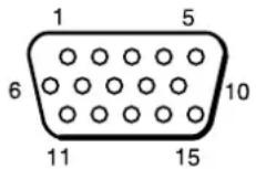
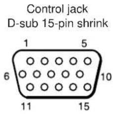
Connection to the control signal terminal (continued)
CONTROL signal jack
| Pin no. RS-232C | Mouse | |||
| PS/2 A | DB Serial | |||
| 1 | ||||
| 2 CLK | ||||
| 3 DATA DATA | ||||
| 4 | ||||
| 5 | ||||
| 6 SELO SELO SELO | ||||
| 7 RTS RTS RTS RTS | ||||
| 8 | ||||
| 9 +5V | +5V | |||
| 10 | GND | GND GND | GND | |
| 11 | ||||
| 12 | ||||
| 13 RD | ||||
| 14 | TD | TD | ||
| 15 | ||||
ADB (Mac) mouse
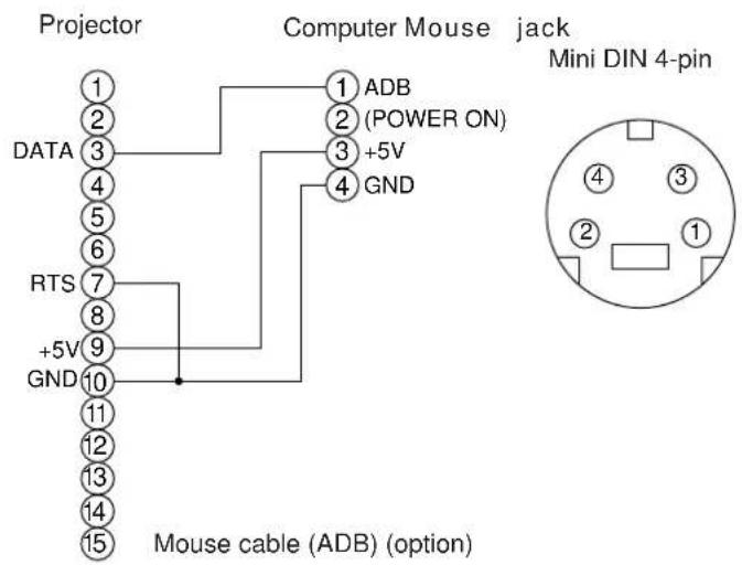
text_image
Projector 1 2 3 DATA 4 5 6 RTS 7 8 +5V 9 GND 10 11 12 13 14 15 Computer Mouse jack 1 ADB 2 (POWER ON) 3 +5V 4 GND Mouse cable (ADB) (option) Mini DIN 4-pinSerial mouse
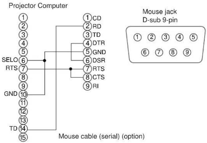
text_image
Projector Computer ① ② ③ ④ ⑤ SELO 6 RTS 7 GND 10 11 12 13 14 TD 15 ①CD ②RD ③TD ④DTR ⑤GND ⑥DSR ⑦RTS ⑧CTS ⑨RI Mouse jack D-sub 9-pin ①②③④⑤ ⑥⑦⑧⑨ Mouse cable (serial) (option)Connection to the control signal terminal (continued)
2. RS232C communication
(1) Turn off the projector and computer power supplies and connect with the RS232C cable.
(2) Turn on the computer power supply and, after the computer has started up, turn on the projector power supply.
(3) Refer to page 21 and set the communication speed and the number of communication bits.
(4) Start RS232C communication.
text_image
Control jack D-sub 15-pin shrink 1 5 6 10 11 15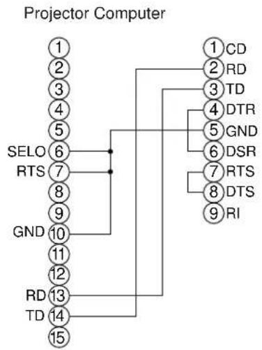
flowchart
graph TD
    A["1"] --> B["2"]
    B --> C["3"]
    C --> D["4"]
    D --> E["5"]
    E --> F["6"]
    F --> G["7"]
    G --> H["8"]
    H --> I["9"]
    I --> J["10"]
    J --> K["11"]
    K --> L["12"]
    L --> M["RD"]
    M --> N["TD"]
    N --> O["13"]
    O --> P["14"]
    P --> Q["15"]
    R["1"] --> S["2"]
    S --> T["3"]
    T --> U["4"]
    U --> V["DTR"]
    V --> W["5"]
    W --> X["GND"]
    X --> Y["6"]
    Y --> Z["DSR"]
    Z --> AA["7"]
    AA --> AB["RTS"]
    AB --> AC["8"]
    AC --> AD["DTS"]
    AD --> AE["9"]
    AE --> AF["RI"]
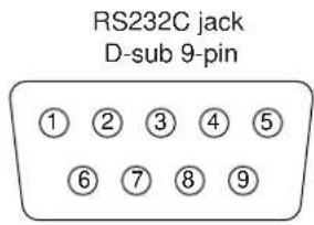
text_image
RS232C jack D-sub 9-pin ① ② ③ ④ ⑤ ⑥ ⑦ ⑧ ⑨RS232C cable
| Projector→computer Computer | →projector | ||||
| Command | Response code Inquiry code Setting code | Default setting code | |||
| 1st 2nd data 1st 2nd data 1st 2nd | |||||
| MOUSE 11h 05h +1 | 20h 05h 31h 05h +1 40h | 05h | |||
| COMMUNICATE 11h | 06h +1 20h 06h 31h 06h | +1 40h 06h | |||
| POWER 11h 11h +1 | 20h 11h 31h 11h +1 | — | |||
| ZOOM | 11h 12h +1 | — | 31h 12h +1 | — | |
| FOCUS | 11h 13h +1 | — | 31h 13h +1 | — | |
| MIRROR | 11h 14h +1 20h 14h 31h 14h +1 40h 14h | ||||
| INPUT 11h 21h +1 20h 21h 31h 21h +1 40h 21h | |||||
| (VIDEO)SYSTEM 12h | 22h +2 20h 22h | 32h 22h +2 40h 22h | |||
| VOLUME | 11h 23h +1 | 20h 23h | 31h 23h +1 | 40h 23h | |
| MUTE | 11h 24h +1 | 20h 24h | 31h 24h +1 | 40h 24h | |
| BRIGHT 13h 31h +3 | 20h 31h 33h | 31h +3 | 40h 31h | ||
| CONTRAST | 13h 32h +3 | 20h 32h | 33h 32h +3 | 40h 32h | |
| COLOR | 13h 33h +3 | 20h 33h | 33h 33h +3 | 40h 33h | |
| TINT | 13h 34h +3 | 20h 34h | 33h 34h +3 | 40h 34h | |
| SHARPNESS | 13h 35h +3 | 20h 35h | 33h 35h +3 | 40h 35h | |
| H.PHASE | 13h 37h +3 | 20h 37h | 33h 37h +3 | 40h 37h | |
| H.POSIT | 14h 38h +4 | — | 34h 38h +4 40h 38h | ||
| H.SIZE | 14h 36h +4 | — | 34h 36h +4 40h 36h | ||
| V.POSIT | 14h 3Ah +4 | — | 34h 3Ah +4 | 40h 3Ah | |
| COLOR BALANCE R | 13h 3Bh +3 | 20h 3Bh | 33h 3Bh +3 | 40h 3Bh | |
| COLOR BALANCE B | 13h 3Dh +3 | 20h 3Dh | 33h 3Dh +3 | 40h 3Dh | |
| AUTO ADJUST | 11h 3Ch +1 | 20h 3Ch | 31h 3Ch +1 | 40h 3Ch | |
| BLANK | 11h 41h +1 | 20h 41h | 31h 41h +1 | 40h 41h | |
| MAGNIFY | 11h 15h +1 | 20h 15h | 31h 15h +1 | 40h 15h | |
| FREEZE | 11h 16h +1 | 20h 16h | 31h 16h +1 | 40h 16h | |
Connection to the control signal terminal (continued)
Command data chart
| Item Data code | |
| MOUSE 00h=disable | mouse function, 01 ~ 7Fh=start mouse function |
| COMMUNICATE 0Xh | 8N1, 1Xh=7N1X0h=1200bps, X1h=2400bps, X2h=4800bps, X3h=9600bps, X4h=19200bps |
| POWER 3Eh=power off (standby status), 3Fh=power on | |
| ZOOM 01 ~ 3Fh=Zoom +, 41 ~ 7Fh=Zoom - | |
| FOCUS 01 ~ 3Fh=Focus +, 41 ~ 7Fh=Focus - | |
| MIRROR 00h=Normal, 01h=H : Invert, 02h=V : Invert, 03h=H & V : Invert | |
| INPUT 11h=VIDEO, 21h=RGB1, 22h=RGB2 | |
| SYSTEM (VIDEO) 00h 00h=Auto, 00h 01h=NTSC, 00h 04h=NTSC4. 4300h 02h=PAL, 00h 03h=SECAM, 00h 05h=M-PAL, 00h 06h=N-PAL | |
| VOLUME 00h (low volume) ~ 24h (high volume) | |
| MUTE 00h=mute off, | 01h=mute on |
| BRIGHT 00h 00h 00h (dark) ~ 00h 00h 24h (bright) | |
| CONTRAST | 00h 00h 00h (low) ~ 00h 00h 24h (strong) |
| COLOR | 00h 00h 00h (pale) ~ 00h 00h 24h (dense) |
| TINT | 00h 00h 00h (reddish) ~ 00h 00h 24h (greenish) |
| SHARPNESS | 00h 00h 00h (soft) ~ 00h 00h 24h (sharp) |
| H.PHASE | 00h 00h 00h ~ 00h 00h 24h |
| H.POSIT | 00h 00h 00h 01h (Right) moves one step00h 00h 00h 7Fh (Left) moves one step |
| H.SIZE | 00h 00h 00h 01h (Large) moves two step00h 00h 00h 7Fh (Small) moves two step |
| V.POSIT | 00h 00h 00h 01h (Up) moves one step00h 00h 00h 7Fh (Down) moves one step |
| COLOR BALANCE R | 00h 00h 00h (Light red) ~ 00h 00h 24h (Dark red) |
| COLOR BALANCE B | 00h 00h 00h (Light blue) ~ 00h 00h 24h (Dark blue) |
| AUTO ADJUST | 00h (AUTO ADJUST (Play)) |
| BLANK | 0Xh=blanking off, 1Xh=blanking onX=8 Black, X=9 Blue, X=F White |
| MAGNIFY | 00h=normal display, 01h=zoom Magnify display or Magnify ratio up.7Fh=zoom ratio down |
| FREEZE | 00h=normal display, 01h=still image display |
The command code configuration consists of a 2-byte command and the following data.
- The first byte of a command indicates the command type with 3 bits on the MSB side and the data length with 4 bits on the LSB side.
Projector - computer Computer - projector
‘0xH’: Error code ‘2xH’: inquiry code
'1xH': response code '3xH': setting code
‘70H’ : frame error code ‘4xH’ : default setting code
‘x’ indicates the data length (example: x=2 means a 2-byte command).
- The second byte of a command indicates the command contents.
Connection to the control signal terminal (continued)
Requesting projector status
(1) Send the request code ‘20H’ + ‘yyH’ from the computer to the projector.
(2) The projector returns the response code '1xH' + 'yyH' + data to the computer.
Changing the projector settings
(1) Send the setting code ‘3xH’ + ‘yyH’ + data from the computer to the projector.
(2) The projector changes the setting based on the above setting code.
(3) The projector returns the response code '1xH' + 'yyH' + data to the computer.
Caution
The response data in (3) above need not match the setting data in (1).
For example, when the projector cannot set the setting data in (1), the projector may set the closest value. That value will be used as the response data in (3). Or else the projector will return the error code '0xH' + 'yyH' + data.
Using the projector default settings
(1) The computer sends the default setting code '40H' + 'yyH' to the projector.
(2) The projector changes the specified setting to the default value.
(3) The projector returns the default value with the response code '1xH' + 'yyH' = data.
When a command sent by the projector cannot be understood by the computer
(1) The computer sends the command code '3xH', '4xH' or '4xH' + 'yyH' + data to the projector.
(2) When the command sent by the projector cannot be understood, the error command ‘00H’ + ‘yyH’ is returned by the computer.
When data sent by the projector cannot be understood
(1) The computer sends the command code '3xH', '4xH' or '4xH' + 'yyH' + data to the projector.
(2) When the command sent by the projector cannot be understood, the error code '0xH' + 'yyH' + data is returned.
When the data length is greater than indicated by the data length code, the projector will ignore the excess data code. Conversely, when the data length is shorter than indicated by the data length code, an error code will be returned to the projector.
When a frame error occurs
Repeats 10 times per second until there is some sort of response to the error code 70H + 70H.
When the interval between bytes in one command is 500ms or greater
When a command or data is not sent within 500ms after the command code ‘2xH’, ‘3xH’ or ‘4xH’ is sent by the computer, the error command ‘70H’ + ‘70H’ will be returned as soon as the 500ms elapses. After this, if there is no response within 1 sec., a frame error will occur.
Caution
- Operation cannot be guaranteed when the projector receives an undefined command or data.
- Provide an interval of at least 40ms between the response code and any other code.
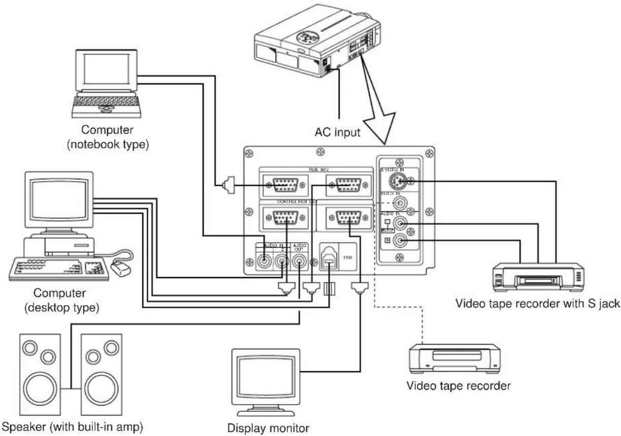
Example of system setup
flowchart
graph TD
    A["Computer (notebook type)"] --> B["AC input"]
    C["Computer (desktop type)"] --> B
    D["Speaker (with built-in amp)"] --> B
    E["Display monitor"] --> B
    F["Video tape recorder with S jack"] --> B
    G["Video tape recorder"] --> B
    H["PCB/USB"] --> B
    I["AC input"] --> B
    J["PCB/USB"] --> B
    K["AC input"] --> B
    L["PCB/USB"] --> B
    M["AC input"] --> B
    N["AC input"] --> B
    O["AC input"] --> B
    P["AC input"] --> B
Caution
Turn power off to all devices before connecting.
Refer to the instruction manual of each device before connecting.
Cleaning the Air filter
Clean the air filter about every 100 hours.
1 Turn off the MAIN POWER switch of the projector and pull out the power cord.
2 Remove the front air filter.
natural_image
Line drawing of a projector with a circular vent and ventilation slots (no text or symbols)| Filter Parts | Number |
| Air Filter MU0 | 0831 |
Cleaning the Air filter (continued)
3 Cleaning the air filter with a vacuum cleaner
4 Installing the air filter
Caution
When the air filter becomes clogged with dust, etc., the projector power may turn off to prevent the internal heat level rising. (The lamp indicator color changes to red.) Do not operate the projector with the air filter removed. (If used with the air filter removed, dust can enter the LCD panel and produce an adverse effect on image quality.)
Lamp
The light source lamp has a service life.
When used for an extended time, the images may become darker and the colors may deteriorate.
A malfunction could occur if the projector is used in this condition, so replace the lamp with a new one.
The following indicator or a message which appears when the power is turned on will indicate when the lamp should be replaced.
At such time, it is necessary to replace the lamp with a new one. For lamp replacement, please contact your dealer or service company.
Caution
Even when the lamp is at a high temperature, the power to the projector may cut off to prevent an excessive temperature increase inside the projector. (The POWER indicator turns off.) Turn off the MAIN POWER switch, wait for some 20 minutes and turn on the MAIN POWER switch again. If the projector is not recovered after turning on the MAIN POWER switch, please contact your dealer or service company.
Message table
Screen displays
The following messages are displayed on the screen.
| CHANGE THE LAMP“CALL A MAINTENANCE PERSON” | The total lamp usage time is nearing the service life of the lamp. Replace with a new lamp.The lamp will turn off automatically when the lamp replacement time has been exceeded. *1 |
| “CHANGE THE LAMP” “CALL A MAINTENANCE PERSON” “THE POWER WILL TURN OFF AFTER * hr.” | The total lamp time is nearing the lamp replacement time. After (*) hours, the lamp will turn off. Quickly replace with a new lamp. *1*Indicates the number of hours until the lamp turns off automatically. |
| Blinking of “CHANGE THE LAMP” | The total lamp time has exceeded the replacement time. The indicator will blink for approximately 10 min. and then turn off automatically. Replace with a new lamp. |
| NO INPUT IS DETECTED | There is no signal input (refer to pages 22, 23). |
| SYNC IS OUT OF RANGE | The current horizontal or vertical frequency cannot be used by this projector (refer to pages 23, 24). |
*1 This display will disappear after 3min. but will reappear when the power is turned on again.
Indicators
The POWER indicator, LAMP indicator and TEMP indicator light or blink in the following cases.
| POWER indicator | LAMP indicator | TEMP indicator | Status | Processing |
| Lights orange | Turns off | Turns off | Standby status | ____ |
| Flashes green | Turns off | Turns off | Warming up | ____ |
| Lights green | Turns off | Turns off | Operation status *1 | ____ |
| Flashes orange | Turns off | Turns off | Cool down | ____ |
| Lights red | Lights red | Turns off | The lamp does not light. *2 The interior is too hot. | Wait some time (approx. 20 min.) before turning the power on again. Clean the air filter before turning the power on. If the indicator still lights, contact your dealer. |
| Lights red | Flashes red | Turns off | A lamp has not been inserted or the lamp cover is missing. | Contact your dealer. |
| Lights red | Turns off | Flashes red | The cooling fan is not operating. | Contact your dealer. |
| Flashes red | Flashes red | Turns off | The total lamp time has exceeded the replacement time. | Contact your dealer. |
When the LAMP or TEMP indicator lights or flashes, turn off the MAIN POWER switch before proceeding. If the problem still persists, contact your dealer or service company.
*1: When the cooling fan is stopped and the interior becomes overheated, the power will turn off automatically to allow cooling (the indicator will turn off). In such cases, turn off the projector power, allow the set to cool and then turn the projector power on again. The lamp will then light. If the lamp does not light, contact your dealer or service company.
*2: In some cases, when the air holes becomes blocked and the interior temperature rises, the lamp will be turned off for protection and the LAMP indicator will flash red. In such cases, turn off the MAIN POWER switch, allow the set to cool (for approx. 20 min.) and then turn the power on again.
When you think something wrong
Before requesting repair, check in accordance with the following chart. If the situation cannot be corrected, then contact your dealer.
| Symptom | Possible cause | Remedy | Page |
| The power is not turned on. | •The main power switch is not turned on.•The power cord is disconnected. | •Turn on the main power switch.•Plug the power cord into an AC power outlet. | P.13P.9 |
| No video or audio. | •The input is not correctly set.•No signal input. | •Use the projector or remote control to set.•Connect correctly. | P.8,10,13,19P.9,31 |
| Video is present but no audio. | •The projector is not correctly connected.•The volume is set to minimum.•Mute is turned on.•Audio is switched to RGB when P in P is on. | •Connect correctly.•Press VOLUME + on the remote control or display the menu screen and adjust the volume.•Press the MUTE button.•Displays the Volume bar and switches the Audio input. | P.9,31P.10,18P.8,10P.10 |
| Audio is present but no video. | •The projector is not correctly connected.•The brightness adjustment knob is rotated fully clockwise.•The lens cap is still on. | •Connect correctly.•Select BRIGHT with the MENU button and then press the ( ▶ ) key.•Remove the lens cap. | P.9,31P.17P.13 |
| Colors are pale and color matching is poor. | Color density and color matching are not correctly adjusted. | Adjust the video. | P.18 |
| Images are dark. | •Brightness and contrast are not correctly adjusted.•The lamp is nearing the end of its service life. | •Adjust the video.•Replace with a new lamp. | P.18P.32 |
| Video is blurred. | Focus or H PHASE is out of adjustment. | Adjust the focus or H PHASE. | P.13,18 |
| The LAMP indicator lights red. | Lamp failure. | Wait approximately 20 min. and then turn the power on again. | P.33 |
| Internal overheating. | •Make sure the ventilation openings are not blocked.•Clean the air filter.•Lower the ambient temperature to 35 degrees C or less. | P.31,32 |
A bright dot may be seen in the picture. This is a phenomenon peculiar to the liquid crystal and is not a problem.
| Product name Liquid crystal projector | |
| Model CP-X958W/E CP-X960W/E | |
| Display method Three liquid crystal panels, three primary color system. | |
| Liquid crystal Panel size 3.3 cm (1.3 type)panel Drive system | TFT active matrix |
| Number of pixels 786,432 pixels (1,024 horizontal · 768 vertical) | |
| Lens Zoom lens F=1.7~2.3 f=49~64mm | |
| Lamp 190w UHB | |
| Speaker 1.2W + 1.2W (Stereo) | |
| Power supply AC100 ~ 120V, 3.7A / AC220 ~ 240V, 1.5A. | |
| Power consumption 320W | |
| Operating temperature range | 0 ~ 35°C |
| Size | 11" (W) · 5" (H) · 14" (D), 289mm(W) · 124mm(H) · 345mm(D) |
| Weight (mass) | 13 lbs, 5.9kg |
| VIDEO signal input jacks | S VIDEO: mini DIN 4-pin jackVIDEO: RCA jackAUDIO: RCA jack |
| RGB signal input/output jacks | RGB signals: D-sub 15-pin shrink jackAudio: stereo mini-jack |
| CONTROL signal jack | D-sub 15-pin shrink jack |
| USB jack | B type |
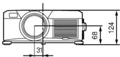
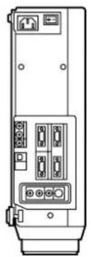
Dimensional Diagram
Unit: inches
natural_image
Technical line drawing of a device rear panel with ports and connectors (no text or symbols)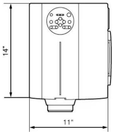
text_image
14" 11"
natural_image
Technical line drawing of a mechanical device with ventilation slots and a handle (no text or symbols)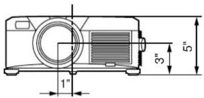
text_image
1" 3" 5"About the warranty and after-service
About the warranty
A warranty is provided for this product. Fill in the necessary items and store in a safe place.
About after-service
When a problem occurs, please check first using the Troubleshooting Chart provided in this instruction manual. If the problem still persists, contact your dealer or service company.
About repairs during the warranty period
Repairs will be made as described in the warranty.
For details, please read the warranty.
Repairs after the warranty period has elapsed
Paid repairs will be made if desired in the event that the function can be restored by such repairs.
Parts will be made available for a minimum period of 8 years.
HITACHI
natural_image
Line drawing of a projector with ventilation slots and a circular vent (no text or symbols)Kurzbeschreibung
text_image
Diagram of a remote control with warning symbols including a triangular symbol and a prohibition sign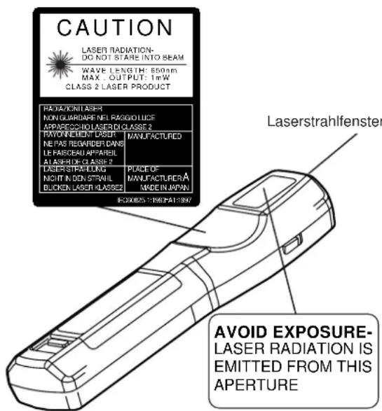
text_image
CAUTION LASER RADIATION- DO NOT STARE INTO BEAM WAVE LENGTH: 550nm MAX. OUTPUT: 1mW CLASS 2 LASER PRODUCT RADIATION LASER NON GUARDWARE NEI PAGGIOLICE APPARECCHOLASER DI CLASSE 2 PAYONNEMENT LASER NE PAS REGARDER DANS LE FASSEAU APPAREL AL ASERIOE CLASSE 2 LASER STRAFLING NOIT IN DEN STRAIL BLOCKEN LASER CLASSE 2 MANUFACTURED PLACE OF MANUFACTURER A MODE IN JAPAN EC204825-11963411997 Laserstrahlfenster AVOID EXPOSURE- LASER RADIATION IS EMITTED FROM THIS APERTURE
Vorsicht
natural_image
Line drawing of a projector with ventilation slots and a circular vent (no text or symbols)Projektor

Fernbedienungsteil
natural_image
Illustration of a hand holding a tool or device with an arrow indicating direction (no text or symbols present)
text_image
Technical diagram of a projector with labeled parts including front, top, and side views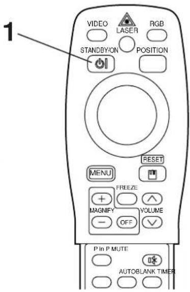
text_image
1 VIDEO LASER RGB STANDBYON POSITION MENU RESET FREEZE MAGNIFY VOLUME OFF P in P MUTE AUTOBLANK TIMERtext_image
EISTLEINGB QPT.ABBLD KOM-GSCHW ▶ KOM-BITS ▶ TIMER ▶ SPRACHE ▶ AUTOM-AUS ▶ SYNC EING ▶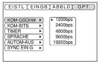
text_image
EISTL EINGB ABBLD OPT. KOM-GSCHW ▶ 1200bps KOM-BITS ▶ 2400bps TIMER ▶ 4800bps SPRACHE ▶ 9600bps AUTOM-AUS ▶ 19200bps SYNC EIN G ▶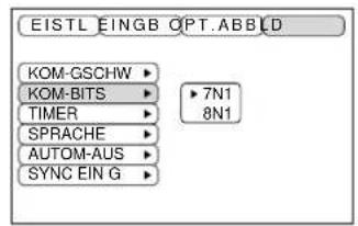
text_image
EISTL EINGB OPT.ABBLD KOM-GSCHW ▶ KOM-BITS ▶ TIMER ▶ SPRACHE ▶ AUTOM-AUS ▶ SYNC EIN G ▶ ▶ 7N1 8N1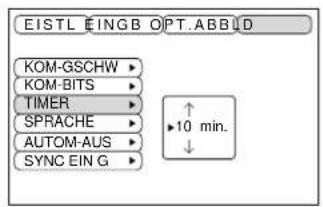
text_image
EISTL EINGB OPT.ABBID KOM-GSCHW ▶ KOM-BITS ▶ TIMER ▶ SPRACHE ▶ AUTOM-AUS ▶ SYNC EIN G ▶ ↑ 10 min. ↓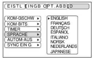
text_image
EISTL EINGB OPT.ABBID KOM-GSCHW > KOM BITS > TIMER > SPRACHE > AUTOM-AUS > SYNC EIN G > ENGLISH FRANÇAIS DEUTSCH ESPAÑOL ITALIANO NORSK NEDERLANDS JAPANESE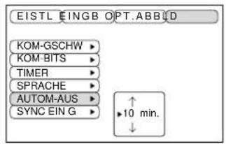
text_image
EISTL EINGB OPT.ABBID KOM-GSCHW ▶ KOM-BITS ▶ TIMER ▶ SPRACHE ▶ AUTOM-AUS ▶ SYNC EIN G ▶ 10 min.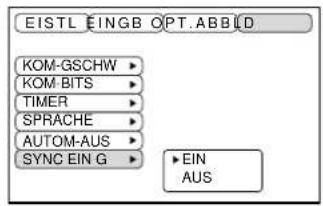
text_image
EISTL EINGB OPT.ABBID KOM-GSCHW ▶ KOM-BITS ▶ TIMER ▶ SPRACHE ▶ AUTOM-AUS ▶ SYNC EIN G ▶ ▶EIN AUSnatural_image
Line drawing of a projector with a circular vent and side panel, no text or symbols present| Filter Teilenummer | |
| Luftfilter MU00831 |
natural_image
Technical line drawing of a device rear panel with ports and connectors (no text or symbols)
text_image
345 289
natural_image
Technical line drawing of a mechanical device with no visible text or symbols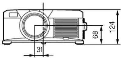
text_image
31 68 124Zur Garantie
natural_image
Line drawing of a projector with a circular vent and ventilation slots (no text or symbols)Données générales
text_image
Diagram of a remote control with warning symbol and prohibition signnatural_image
Line drawing of a projector with ventilation slots and a circular vent (no text or symbols)Projecteur

Télécommande
natural_image
Line drawing of a hand holding a cylindrical object with an arrow indicating upward motion (no text or symbols)text_image
Technical diagram of a projector with labeled parts including front, top, and side views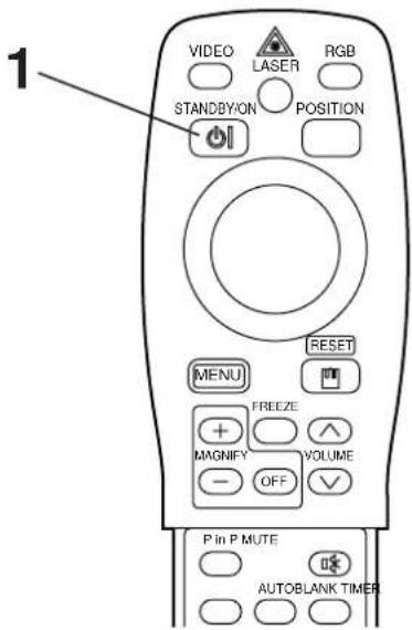
text_image
1 VIDEO LASER RGB STANDBYON POSITION MENU RESET FREEZE MAGNIFY VOLUME OFF P in P MUTE AUTOBLANK TIMERnatural_image
Line drawing of a projector with ventilation slots and a circular vent (no text or symbols)natural_image
Technical line drawing of a device rear panel with ports and connectors (no text or symbols)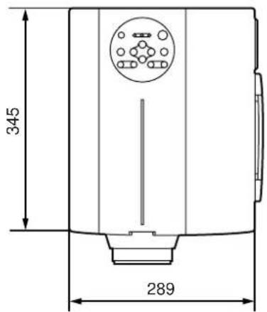
text_image
345 289
natural_image
Line drawing of a mechanical device with a central handle and side ports (no text or symbols)
text_image
31 68 124Garantie
natural_image
Line drawing of a projector with ventilation slots and a circular vent (no text or symbols)Profilo
Interesting parts of images can be magnified for closer viewing.
text_image
Diagram of a remote control with warning symbols including a triangular symbol and a prohibition sign
text_image
CAUTION LASER RADIATION- DO NOT STARE INTO BEAM WAVE LENGTH: 850mm MAX. OUTPUT: 1mW CLASS 2 LASER PRODUCT PANIONAL LASER MONGUARDAREN RACGOLICE APPEECCIO LASER CLASSE 2 FAVYINLESTER LASER NEVAS REMODEDANE LE FRADESCA APPEARL AL ASER DE CLASSE 2 LASER STRATLLIG NICHT IN DEN STRAIL BLOCK LASER CLASS 2 PLACE OF MANUFACTURERS A MADE IN JAPAN EDUING 11963411997Uscita raggio laser
text_image
NGITT IN DEN STRAWIL BLOCKEN LASER KLASSE MANUFACTURERA WIDE IN JAPAN EC00625 1:1963-41:1997 AVOID EXPOSURE- LASER RADIATION IS EMITTED FROM THISAVOID EXPOSURE- LASER RADIATION IS EMITTED FROM THIS APERTURE

Attenzione
natural_image
Line drawing of a projector with ventilation slots and a circular vent (no text or symbols)text_image
HITACHI CP-X956W/E CP-X960W/E Capital Crystal Projector influding parts Pliomagnetic-Projector anionine/ultronic acid Inorganic compound Ispole anionine/ultronic acid Protease-L contract ligand and 2D3/4/2018 Propion or phase in solid phase influding, non-influding Extralactation Projector anionine/ultronic acid Pyrene crystal projector unlabeled parts(1) Used to select menu items when the menu screen is displayed (refer to page 16–18).
natural_image
Line drawing of a hand holding a cylindrical object with an arrow indicating upward motion (no text or symbols)
text_image
Technical diagram of a projector with labeled parts including front, top, and side views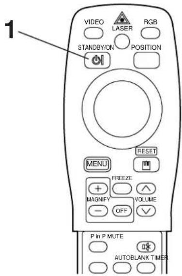
text_image
1 VIDEO LASER RGB STANDBY/ON POSITION MENU RESET FREEZE MAGNIFY VOLUME OFF P in P MUTE AUTOBLANK TIMERnatural_image
Line drawing of a projector with a circular vent and ventilation slots (no text or symbols)natural_image
Technical line drawing of a device rear panel with ports and connectors (no text or symbols)
text_image
345 289
natural_image
Technical line drawing of a mechanical device with no visible text or symbols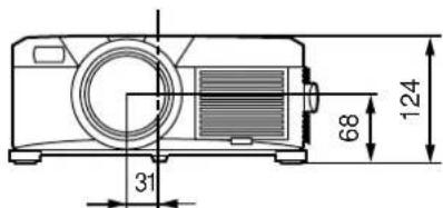
text_image
31 68 124Garanzia
natural_image
Line drawing of a projector with a circular vent and ventilation slots (no text or symbols)Generalidades
text_image
Diagram showing a remote control with a warning symbol (triangular) and no prohibition sign, indicating no danger or absence of the device.natural_image
Line drawing of a projector with a circular vent and ventilation slots (no text or symbols)natural_image
Illustration of a hand holding a tool with an arrow indicating direction (no text or symbols)
Instale las pilas.
text_image
Diagram of a projector with numbered parts labeled 1 through 7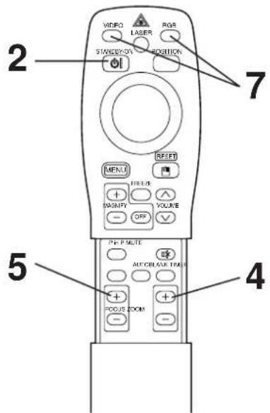
text_image
VIDEO LASER RGB STRAWSON POSITION 2 7 5 4 P/P SUTE AUTO/CLEAR ITEMS AUCRUM STARS POCKS ZOOMtext_image
Technical diagram of a projector with labeled parts including front, top, and side views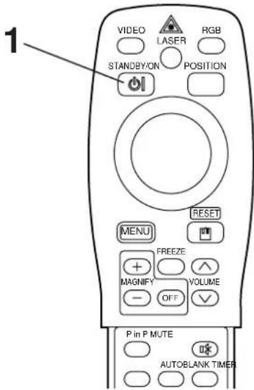
text_image
1 VIDEO LASER RGB STANDBY/ON POSITION MENU RESET FREEZE MAGNIFY VOLUME OFF Pin PMUTE AUTOBLANK TIMERnatural_image
Line drawing of a projector with a circular vent and ventilation slots (no text or symbols)When you think something wrong
natural_image
Technical line drawing of a device rear panel with ports and connectors (no text or symbols)
text_image
345 289
natural_image
Line drawing of a mechanical device with a central handle and side ports (no text or symbols)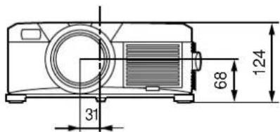
text_image
31 68 124natural_image
Line drawing of a projector with ventilation slots and a circular vent (no text or symbols)Overzicht
text_image
Diagram of a remote control with warning symbol and prohibition sign
text_image
CAUTION LASER RADIATION DO NOT STARE INTO BEAM WAVE LENGTH: 650nm MAX. OUTPUT: 1mW CLASS 2 LASER PRODUCT TADIATION LASER NON GUARDARE NET RAGRIC LUCE APPARECANT LASER CLASSE 2 PROMATOEN TINUSER (MANUFACTURED) NE PAS REGARDER DANS LE FAISCEAU APPAREL A LASER DE CLASSE 2 LASER STRAPFLOURS NCH INDIVSTRAL BUCKEN LASER CLASSE 2 PLACE OF MANUFACTURORA MADE IN JAPAN IEC0825-11J09 HA11007natural_image
Illustration of a hand holding a tool or device with an arrow indicating direction (no text or symbols present)
Leg de batterijen in de houder.
text_image
SETUP INPUT OPT.BEELD COM. SNELH ▶ COM. BITS ▶ TIMER ▶ TAAL ▶ AUTO UIT ▶ SYNC ON G ▶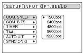
text_image
SETUP INPUT OPT.BEELD COM. SNELH ▶ 1200bps COM. BITS ▶ 2400bps TIMER ▶ 4800bps TAAL ▶ 9600bps AUTO UIT ▶ 19200bps SYNC ON G ▶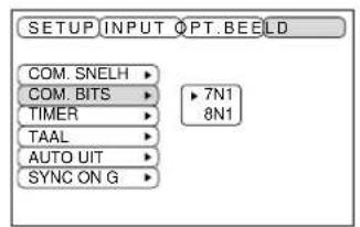
text_image
SETUP INPUT OPT.BEELD COM. SNELH ▶ COM. BITS ▶ TIMER ▶ TAAL ▶ AUTO UIT ▶ SYNC ON G ▶ 7N1 8N1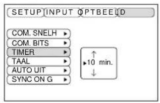
text_image
SETUP INPUT OPTBEEID COM. SNELH > COM. BITS > TIMER > TAAL > AUTO UIT > SYNC ON G > 10 min. ↓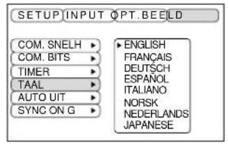
text_image
SETUP INPUT OPT.BEELD COM. SNELH ▶ COM. BITS ▶ TIMER ▶ TAAL ▶ AUTO UIT ▶ SYNC ON G ▶ ► ENGLISH FRANÇAIS DEUTSCH ESPAÑOL ITALIANO NORSK NEDERLANDS JAPANESE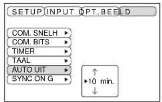
text_image
SETUP INPUT OPT.BEELD COM. SNELH > COM. BITS > TIMER > TAAL > AUTO UIT > SYNC ON G > 10 min.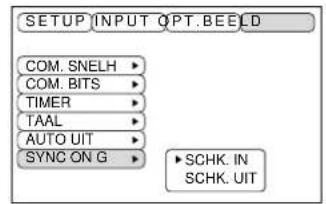
text_image
SETUP INPUT OPT.BEELD COM. SNELH > COM. BITS > TIMER > TAAL > AUTO UIT > SYNC ON G > SCHK. IN SCHK. UITProjector – computer Computer – projector
natural_image
Line drawing of a projector with a circular vent and side panel (no text or symbols)natural_image
Technical line drawing of a device rear panel with ports and connectors (no text or symbols)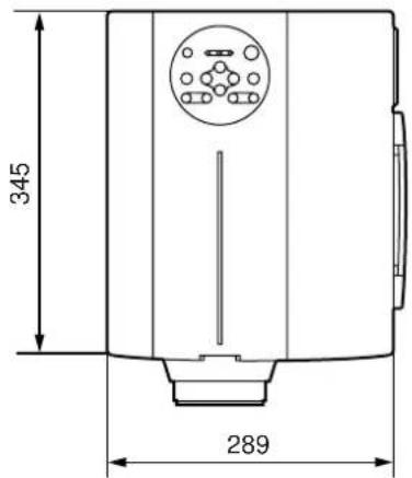
text_image
345 289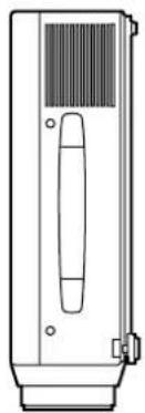
natural_image
Line drawing of a mechanical device with a central handle and ventilation grille (no text or symbols)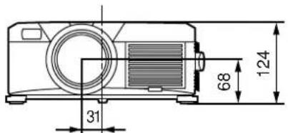
text_image
31 68 124Betreffende de garantie
natural_image
Line drawing of a projector with a circular vent and ventilation slots (no text or symbols)Oversikt
text_image
Diagram showing a remote control with warning symbol and prohibition sign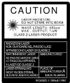
text_image
CAUTION LASER RADIATION DO NOT STARE INTO BEAM WAVE LENGTH: 650mm MAX. OUTPUT: 1mW CLASS 2 LASER PRODUCT RADIATION LASER NON GUITABLE NO. RADICOLUXE APPAROCH LASER BCLASSE 2 RAYONEVENT LASER NE PAS DESARDER DANS LE FASSEAU APPAREL ALASER DE CLASSE 2 LASER STRAFLUO NICHT IN DEN STRAFL BUCENT ASHER ASSET PLACE OF MANUFACTURER A MADE FLAPAN ISO:8825-11934-A1 1997Lasersender
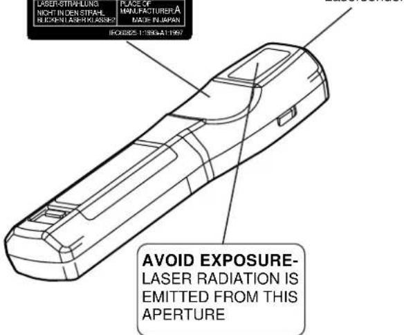
text_image
NOFT-INDEN STRAL HICKEN LASER KLASSE2 MANUFACTURER A MADE IN JAPAN IPD0025-1180A11997 AVOID EXPOSURE- LASER RADIATION IS EMITTED FROM THIS APERTURE
Forsiktig
natural_image
Line drawing of a projector with lens and control panel (no text or symbols)Prosjektør

Fjernkontroll
Batterier for fjernkontroll
text_image
HITACHI CP-X956W/E CP-X980W/E Capital Crystal Producter inforcing system Pilomagnadiol Producter inforcing system Vibogaster Limited System inforcing system Protezile L-conductor Insulator and ICS13 production Protezile on the steel rod inductor, or wire feedstock Enplanation Productor inforcing system Pyrene Enplanation Productor inforcing systemBruksanvisning (dette dokumentet)
CP-X958W
CP-X960W
CP-X958E
CP-X960E
Strømledning
110V-US
220-UK, Europa
220-UK, Europa
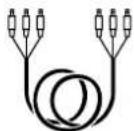
3-pluggs
audio/video
kabel R

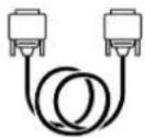
(15-15 pin M/M)
natural_image
Line drawing of a projector with ventilation slots and a circular button (no text or symbols)natural_image
Illustration of a hand holding a cylindrical object with an arrow indicating upward motion (no text or symbols)text_image
Technical diagram of a projector with labeled parts including front, top, and side views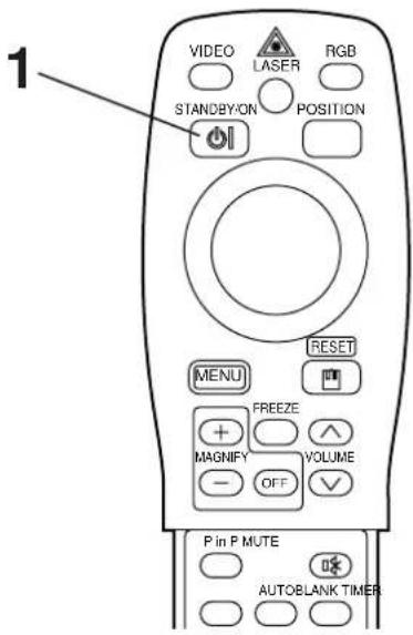
text_image
1 VIDEO LASER RGB STANDBYON POSITION MENU FREETE MAGNIFY VOLUME OFF P in P MUTE AUTOBLANK TIMERnatural_image
Line drawing of a projector with a circular vent and side panel, showing internal components (no text or symbols)| Filter Delnummer |
| Luftfilter MU00831 |
natural_image
Front view of a device chassis with labeled ports and connectors (no text or symbols visible)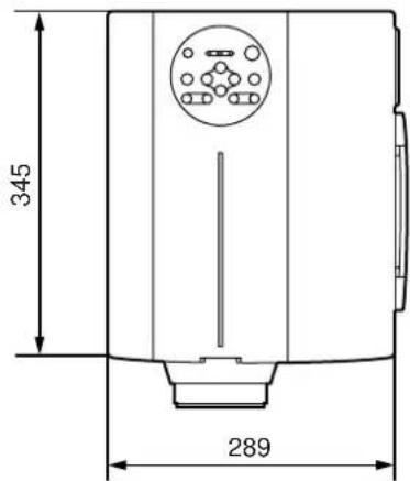
text_image
345 289
natural_image
Line drawing of a mechanical device with internal components and mounting bracket (no text or symbols)