
PIM 640 AS (BK) - Cooker INDESIT - Free user manual and instructions
Find the device manual for free PIM 640 AS (BK) INDESIT in PDF.
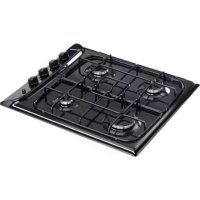



| Brand | Indesit |
| Model | PIM 640 AS (BK) |
| Product type | Built-in gas hob |
| Number of burners | 4 (1 rapid, 2 semi-rapid, 1 auxiliary) |
| Dimensions (W x D x H) | 60 x 52 x 6 cm |
| Weight | 10 kg |
| Power supply | Gas (butane/propane/natural) and 230 V for ignition |
| Total burner power | 7.8 kW |
| Ignition | Integrated electronic ignition with spark plug |
| Safety device | Thermocouple cutting off gas in case of flame failure |
| Materials | Stainless steel, cast iron grates |
| Cleaning and maintenance | Non-abrasive damp sponge; do not use steam cleaner |
| Safety | Hot surfaces indicated, child lock not present |
| Spare parts and repairability | Injectors, burners, grates available; repair by authorized technician |
| General information | Manual in 72 pages, multilingual; energy class not specified |
Frequently Asked Questions - PIM 640 AS (BK) INDESIT
User questions about PIM 640 AS (BK) INDESIT
0 question about this device. Answer the ones you know or ask your own.
Ask a new question about this device
Download the instructions for your Cooker in PDF format for free! Find your manual PIM 640 AS (BK) - INDESIT and take your electronic device back in hand. On this page are published all the documents necessary for the use of your device. PIM 640 AS (BK) by INDESIT.
USER MANUAL PIM 640 AS (BK) INDESIT
Operating Instructions HOB
Contents
Operating Instructions, 1
Warnings, 3
Assistance, 8
Description of the appliance, 10
Installation, 19
Start-up and use, 23
Precautions and tips, 23
Maintenance and care, 24
Troubleshooting, 24
PT
Portuguese
- 1,2,3,4,5,6,7,8,9,10
55.
RU
Russian
Operating Manual
VARIANT
Contents
Operating Manual,2
Precautions,6
Maintenance,9
Description,12
Installation,61
PaindaHny HycKayIbIfbl
NTNTA
Ma3MyHbI
TnndanaHyhckayyIbIfbl,2
Eckenptynep,7
Kemek,9
KpybJIbIcIINaTTamAcbl,12
Ophaty,67
Kocy kHe naDanany,71
CaKaTaHdbIpynap MeH KeHeceTp,71
Kehdey khekyim,72
AkynbkTapdbjxho,72
IT
Avvertenze
WARNING: The appliance and its accessible parts become hot during use. Care should be taken to avoid touching heating elements. Children less than 8 years of age shall be kept away unless continuously supervised. This appliance can be used by children aged from 8 years and above and persons with reduced physical, sensory or mental capabilities or lack of experience and knowledge if they have been given supervision or instruction concerning use of the appliance in a safe way and understand the hazards involved. Children shall not play with the appliance. Cleaning and user maintenance shall not be made by children without supervision.
WARNING: Unattended cooking on a hob with fat or oil can be dangerous and may result in fire. NEVER try to extinguish a fire with water, but switch off the appliance and then cover flame e.g. with a lid or a fire blanket.
WARNING: Danger of fire: do not store items on the cooking surfaces.
Never use steam cleaners or pressure cleaners on the appliance.
Remove any liquid from the lid before opening it. Do not close the glass cover (if present) when the gas burners or electric hotplates are still hot.
The appliance is not intended to be operated by means of an external timer or separate remote control system.
CAUTION: the use of inappropriate hob guards can cause accidents.
Warnings
- the type of problem encountered.
- appliance model (Mod.)
- serial number (S/N)
This information is found on the data plate located on the appliance and/or on the packaging.
Assistance
Provide them with:
(Mod.) of
(S / N)
∴ y/2 + z/2 = 1/2
RU
Maintenance service
To contact technical service:
In case of malfunction; Model (Mod.) Part number (serial number)
You will find this data on the nameplate located on the device.
KZ
Komek
Important information:
- If there is a problem with the device. Contact the manufacturer (Mod.).
- Serial number (S/N).
If the device is defective, contact the manufacturer using the nameplate data.
IT
Description of the appliance
Overall view
- Support Grid for COOKWARE
- GAS BURNERS
- Control Knobs for GAS BURNERS
- GAS BURNERS button
- Ignition for GAS BURNERS
- SAFETY DEVICES*
- GAS BURNERS differ in size and power. Use the diameter of the cookware to choose the most appropriate burner to cook with. Control Knobs for GAS BURNERS adjust the size of the flame.
- GAS BURNER IGNITION enables a specific burner to be lit automatically.
- SAFETY DEVICE* stops the gas flow if the flame is accidentally extinguished.
- Only available on certain models.
FR
BE
NL
! Before operating your new appliance please read this instruction booklet carefully. It contains important information for safe use, installation and care of the appliance.
Please keep these operating instructions for future reference. Pass them on to possible new owners of the appliance.
Positioning
Keep packaging material out of the reach of children. It can become a choking or suffocation hazard (see Precautions and tips).
! The appliance must be installed by a qualified professional according to the instructions provided. Incorrect installation may cause harm to people and animals or may damage property.
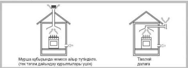
This unit may be installed and used only in permanently ventilated rooms in accordance with current national regulations. The following requirements must be observed: - The room must be equipped with an air extraction system that expels any combustion fumes. This may consist of a hood or an electric fan that automatically starts each time the appliance is switched on.
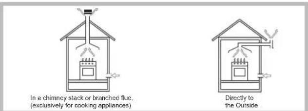
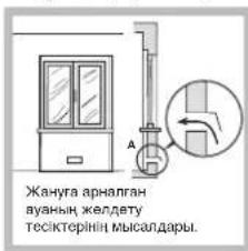
- The room must also allow proper air circulation, as air is needed for combustion to occur normally. The flow of air must not be less than 2 m³ per kW of installed power.
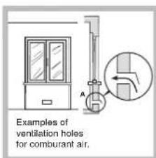
The air circulation system may take air directly from the outside by means of a pipe with an inner cross section of at least 100 cm²; the opening must not be vulnerable to any type of blockages.
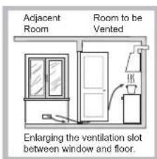
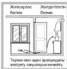
The system can also provide the air needed for combustion indirectly, i.e. from adjacent rooms fitted with air circulation tubes as described above. However, these rooms must not be communal rooms, bedrooms or rooms that may present a fire hazard.
- Liquid petroleum gas sinks to the floor as it is heavier than air. Therefore, rooms containing LPG cylinders must also be equipped with vents to allow gas to escape in the event of a leak. As a result LPG cylinders, whether partially or completely full, must not be installed or stored in rooms or storage areas that are below ground level (cellars, etc.). It is advisable to keep only the cylinder being used in the room, positioned so that it is not subject to heat produced by external sources (ovens, fireplaces, stoves, etc.) which could raise the temperature of the cylinder above 50°C.
Fitting the appliance
The following precautions must be taken when installing the hob:
- Kitchen cabinets adjacent to the appliance and taller than the top of the hob must be at least 200 mm from the edge of the hob.
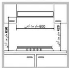
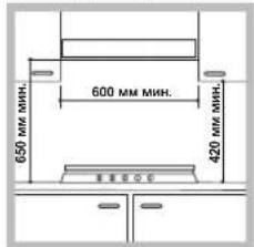
- Hoods must be installed according to their relative installation instruction manuals and at a minimum distance of 650 mm from the hob (see figure).
- Place the wall cabinets adjacent to the hood at a minimum height of 420 mm from the hob (see figure).
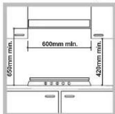
If the hob is installed beneath a wall cabinet, the latter must be situated at a minimum of 700 mm above the hob.
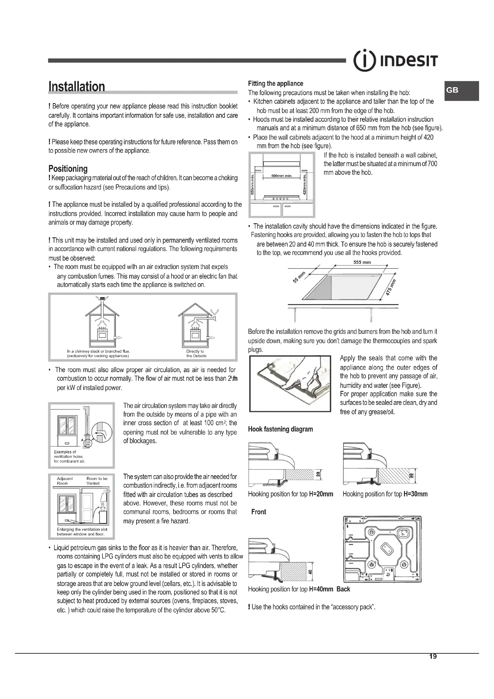
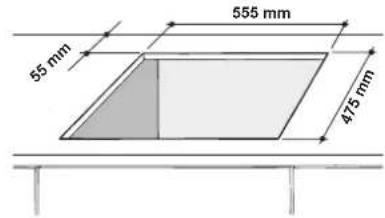
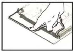
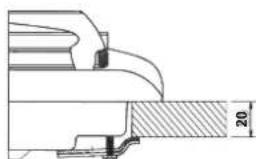
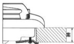
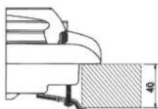
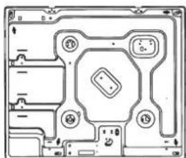
- The installation cavity should have the dimensions indicated in the figure. Fastening hooks are provided, allowing you to fasten the hob to tops that are between 20 and 40 mm thick. To ensure the hob is securely fastened to the top, we recommend you use all the hooks provided.
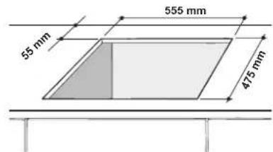
Before the installation remove the grids and burners from the hob and turn it upside down, making sure you don't damage the thermocouples and spark plugs.
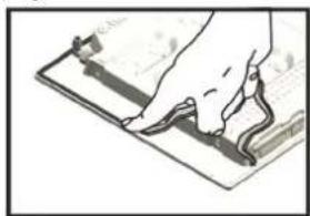
Apply the seals that come with the appliance along the outer edges of the hob to prevent any passage of air, humidity and water (see Figure). For proper application make sure the surfaces to be sealed are clean, dry and free of any grease/oil.
Hook fastening diagram
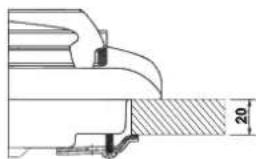
Hooking position for top H=20mm
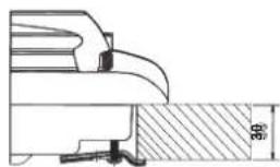
Hooking position for top H=30mm
Front
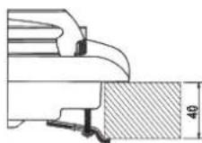
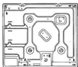
Hooking position for top H=40mm Back
! Use the hooks contained in the "accessory pack".
GB
- Where the hob is not installed over a built-in oven, a wooden panel must be installed as insulation. This must be placed at a minimum distance of 20 mm from the lower part of the hob.
Ventilation
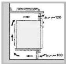
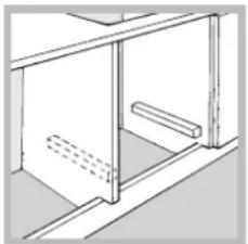
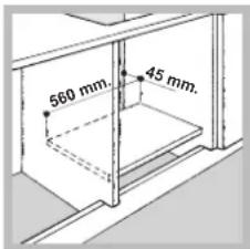
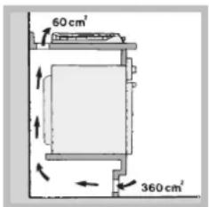
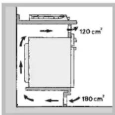
To ensure adequate ventilation, the back panel of the cabinet must be removed. It is advisable to install the oven so that it rests on two strips of wood, or on a completely flat surface with an opening of at least 45 x 560 mm (see diagrams).
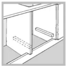
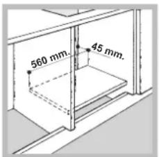
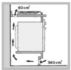
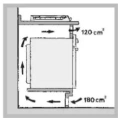
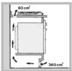
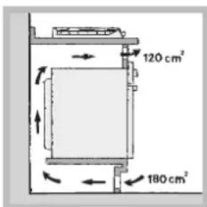
Where a hob is installed above an oven without a forced ventilation cooling system, adequate ventilation must be provided inside the cabinet by means of air holes through which air can pass (see figure).
Electrical connection
Hobs equipped with a three-pole power supply cable are designed to operate with alternating current at the voltage and frequency indicated on the data plate (this is located on the lower part of the appliance). The earth wire in the cable has a green and yellow cover. If the appliance is to be installed above a built-in electric oven, the electrical connection of the hob and the oven must be carried out separately, both for electrical safety purposes and to make extracting the oven easier.
Connecting the supply cable to the mains
Install a standardised plug corresponding to the load indicated on the data plate.
The appliance must be directly connected to the mains using an omnipolar circuit-breaker with a minimum contact opening of 3 mm installed between the appliance and the mains.
The circuit-breaker must be suitable for the charge indicated and must comply with current electrical regulations (the earthing wire must not be interrupted by the circuit-breaker). The supply cable must not come into contact with surfaces with temperatures higher than 50°C.
! The installer must ensure that the correct electrical connection has been made and that it is compliant with safety regulations.
Before connecting to the power supply, make sure that:
- the appliance is earthed and the plug is compliant with the law.
- the socket can withstand the maximum power of the appliance, which is indicated on the data plate.
- the voltage is in the range between the values indicated on the data plate.
- the socket is compatible with the plug of the appliance. If the socket is incompatible with the plug, ask an authorised technician to replace it. Do not use extension cords or multiple sockets.
! Once the appliance has been installed, the power supply cable and the electrical socket must be easily accessible. ! The cable must not be bent or compressed. ! The cable must be checked regularly and replaced by authorised technicians only (see Assistance). ! The manufacturer declines any liability should these safety measures not be observed.
Gas connection
The appliance should be connected to the main gas supply or to a gas cylinder in compliance with current national regulations. Before carrying out the connection, make sure the cooker is compatible with the gas supply you wish to use. If this is not the case, follow the instructions indicated in the paragraph "Adapting to different types of gas."
When using liquid gas from a cylinder, install a pressure regulator which complies with current national regulations.
! Check that the pressure of the gas supply is consistent with the values indicated in Table 1 ("Burner and nozzle specifications"). This will ensure the safe operation and longevity of your appliance while maintaining efficient energy consumption.
Connection with a rigid pipe (copper or steel)
! Connection to the gas system must be carried out in such a way as not to place any strain of any kind on the appliance.
There is an adjustable L-shaped pipe fitting on the appliance supply ramp and this is fitted with a seal in order to prevent leaks. The seal must always be replaced after rotating the pipe fitting (seal provided with appliance). The gas supply pipe fitting is a threaded 1/2 gas cylindrical male attachment.
Connecting a flexible jointless stainless steel pipe to a threaded attachment
The gas supply pipe fitting is a threaded 1/2 gas cylindrical male attachment. These pipes must be installed so that they are never longer than 2000mm when fully extended. Once connection has been carried out, make sure that the flexible metal pipe does not touch any moving parts and is not compressed.
Only use pipes and seals that comply with current national regulations.
Checking the tightness of the connection
! When the installation process is complete, check the pipe fittings for leaks using a soapy solution. Never use a flame.
Adapting to different types of gas
To adapt the hob to a different type of gas other than the default type (indicated on the rating plate at the base of the hob or on the packaging), the burner nozzles should be replaced as follows:
- Remove the hob grids and slide the burners off their seats.
- Unscrew the nozzles using a 7 mm socket spanner, and replace them with nozzles for the new type of gas (see table 1 "Burner and nozzle characteristics").
- Reassemble the parts following the above procedure in the reverse order.
- Once this procedure is finished, replace the old rating sticker with one indicating the new type of gas used. Stickers are available from any of our Service Centres.
- Adjusting the burners' primary air: Does not require adjusting.
- Setting the burners to minimum
- Turn the tap to the low flame position;
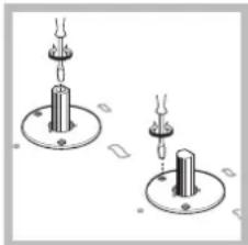
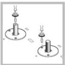
- Remove the knob and adjust the adjustment screw, which is positioned in or next to the tap pin, until the flame is small but steady.
- Having adjusted the flame to the required low setting, while the burner is alight, quickly change the position of the knob from minimum to maximum and vice versa several times, checking that the flame does not go out.
- Some appliances have a safety device (thermocouple) fitted. If the device fails to work when the burners are set to the low flame setting, increase this low flame setting using the adjusting screw.
- Once the adjustment has been made, replace the seals on the by-passes using sealing wax or a similar substance.
! If the appliance is connected to liquid gas, the regulation screw must be fastened as tightly as possible. ! Once this procedure is finished, replace the old rating sticker with one indicating the new type of gas used. Stickers are available from any of our Service Centres. ! Should the gas pressure used be different (or vary slightly) from the recommended pressure, a suitable pressure regulator must be fitted to the inlet pipe (in order to comply with current national regulations).
| DATA PLATE | |
| Electrical connections | see data plate |
| CE | This appliance conforms to the following European Economic Community directives: - 2006/95/EC dated 12/12/06 (Low Voltage) and subsequent amendments - 2004/108/EC dated 15/12/04 (Electromagnetic Compatibility) and subsequent amendments - 93/68/EEC dated 22/07/93 and subsequent amendments. - 2009/142/EC dated 30/11/06 (Gas) and subsequent amendments - 2012/19/EU and subsequent amendments. |
| ECODESIGN | EU Regulation no. 66/2014 implementing Directive 2009/125/EC. standard EN 30-2-1 |
Burner and nozzle specifications
| Table 1 | Liquid gas Natural gas | |||||||||
| Burner Diameter | (mm) | Thermal power kW (p.c.s.*) Reduced Nominal | By-pass 1/100 (mm) (1) | Nozzle 1/100 (mm) *** | Flow* (g/h) *** | Nozzle 1/100 (mm) Nozzle* (l/h) | ||||
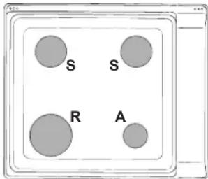
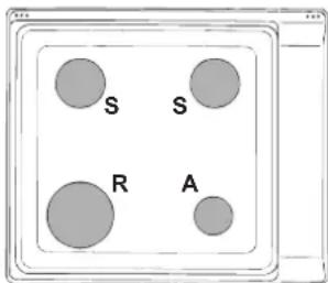
| Rapid (R) | 94 | 0,70 | 3,00 | 39 | 41 | 87 | 218 | 214 | 128 | 286 |
| Semi Rapid (S) | 69 | 0,40 | 1,90 | 28 | 30 | 70 | 138 | 136 | 104 | 181 |
| Auxiliary (A) | 46 | 0,40 | 1,00 | 28 | 30 | 52 | 73 | 71 | 76 | 95 |
| Supply pressures | Nominal (mbar) Minimum (mbar) Maximum (mbar) | 28-30 | 37 | 20 | ||||||
| 20 | 25 | 17 | ||||||||
| 35 | 45 | 25 | ||||||||
(1) Only for appliances with the security device.
- At 15°C and 1013.25 mbar - dry gas Propane P.C.S. = 50.37 MJ/Kg * Butane P.C.S. = 49.47 MJ/Kg
Natural P.C.S. = 37.78 MJ/m
PIM 640AS
PIM 640A
Start-up and use
! The position of the corresponding gas burner is shown on every knob.
Gas burners
Each burner can be adjusted to one of the following settings using the corresponding control knob:
- Off

Maximum

Minimum
To light one of the burners, hold a lit match or lighter near the burner and, at the same time, press down and turn the corresponding knob anti-clockwise to the maximum setting.
Since the burner is fitted with a safety device, the knob should be pressed for approximately 2-3 seconds to allow the automatic device keeping the flame alight to heat up.
When using models with an ignition button, light the desired burner by first pressing the gas burners button (identifiable by the symbol), then pressing down the corresponding knob as far as possible and turning it anticlockwise towards the maximum setting.
! If a flame is accidentally extinguished, turn off the control knob and wait for at least 1 minute before trying to relight it.
To switch off the burner, turn the knob in a clockwise direction until it stops (when reaches the "●" position).
Practical advice on using the burners
To ensure the burners operate efficiently:
- Use appropriate cookware for each burner (see table) so that the flames do not extend beyond the bottom of the cookware. Always use cookware with a flat base and a cover.
- When the contents of the pan reach boiling point, turn the knob to minimum.
| Burner | Ø Cookware Diameter (cm) |
| Rapid (R) | 24 - 26 |
| Semi Rapid (S) | 16 - 20 |
| Auxiliary (A) | 10 - 14 |
To identify the type of burner, refer to the designs in the section entitled, "Bumer and Nozzle Specifications".
Precautions and tips
! This appliance has been designed and manufactured in compliance with international safety standards. The following warnings are provided for safety reasons and must be read carefully.
General safety
This is a class 3 built-in appliance. - Gas appliances require regular air exchange to maintain efficient operation. When installing the hob, follow the instructions provided in the paragraph on "Positioning" the appliance. - These instructions are only valid for the countries whose symbols appear in the manual and on the serial number plate.
- The appliance was designed for domestic use inside the home and is not intended for commercial or industrial use.
- The appliance must not be installed outdoors, even in covered areas. It is extremely dangerous to leave the appliance exposed to rain and storms.
- Do not touch the appliance with bare feet or with wet or damp hands and feet.
- The appliance must be used by adults only for the preparation of food, in accordance with the instructions outlined in this booklet. Any other use of the appliance (e.g. for heating the room) constitutes improper use and is dangerous. The manufacturer may not be held liable for any damage resulting from improper, incorrect and unreasonable use of the appliance.
- The openings used for ventilation and dispersion of heat must never be covered. Always make sure the knobs are in the "●" position when the appliance is not in use.
- When unplugging the appliance always pull the plug from the mains socket, do not pull on the cable.
- Never carry out any cleaning or maintenance work without having detached the plug from the mains.
- In case of malfunction, under no circumstances should you attempt to repair the appliance yourself. Repairs carried out by inexperienced persons may cause injury or further malfunctioning of the appliance. Contact a Service Centre (see Assistance). Always make sure that pan handles are turned towards the centre of the hob in order to avoid accidental burns.
- Do not close the glass cover (if present) when the gas burners or electric hotplates are still hot.
- Do not use unstable or deformed pans.
- The appliance should not be operated by people (including children) with reduced physical, sensory or mental capacities, by inexperienced individuals or by anyone who is not familiar with the product. These individuals should, at the very least, be supervised by someone who assumes responsibility for their safety or receive preliminary instructions relating to the operation of the appliance.
- Do not let children play with the appliance.
- The appliance is not intended to be operated by means of an external timer or separate remote-control system.
Disposal
- When disposing of packaging material: observe local legislation so that the packaging may be reused.
- The European Directive 2012/19/EU on Waste Electrical and Electronic Equipment (WEEE), requires that old household electrical appliances must not be disposed of in the normal unsorted municipal waste stream. Old appliances must be collected separately in order to optimise the recovery and recycling of the materials they contain and reduce the impact on human health and the environment. The crossed out "wheeled bin" symbol on the product reminds you of your obligation, that when you dispose of the appliance it must be separately collected.
Consumers should contact their local authority or retailer for information concerning the correct disposal of their old appliance.
Respecting and conserving the environment
- Cook your food in closed pots or pans with well-fitting lids and use as little water as possible. Cooking with the lid off will greatly increase energy consumption.
- Use purely flat pots and pans.
- If you are cooking something that takes a long time, it's worth using a pressure cooker, which is twice as fast and saves a third of the energy.
Maintenance and care
Switching the appliance off
Disconnect your appliance from the electricity supply before carrying out any work on it.
Cleaning the appliance
! Do not use abrasive or corrosive detergents such as stain removers, anti-rust products, powder detergents or sponges with abrasive surfaces: these may scratch the surface beyond repair.
! Never use steam cleaners or pressure cleaners on the appliance.
- It is usually enough to wash the hob with a damp sponge and dry it with absorbent kitchen roll.
- The removable parts of the burners should be washed frequently with warm water and soap and any burnt-on substances removed.
- For hobs which light automatically, the terminal part of the electronic instant lighting devices should be cleaned frequently and the gas outlet holes should be checked for blockages.
- Stainless steel can be marked by hard water that has been left on the surface for a long time, or by aggressive detergents containing phosphorus. After cleaning, rinse and dry any remaining drops of water.
Gas tap maintenance
Over time, the taps may become jammed or difficult to turn. If this happens, the tap must be replaced.
! This procedure must be performed by a qualified technician authorised by the manufacturer.
Troubleshooting
It may happen that the appliance does not function properly or at all. Before calling the service centre for assistance, check if anything can be done. First, check to see that there are no interruptions in the gas and electrical supplies, and, in particular, that the gas valves for the mains are open.
The burner does not light or the flame is not even around the burner.
Check whether:
- The gas holes on the burner are clogged.
- All the movable parts that make up the burner are mounted correctly.
- There are draughts near the appliance.
The flame dies in models with a safety device.
Check to make sure that:
- You pressed the knob all the way in.
- You keep the knob pressed in long enough to activate the safety device.
- The gas holes are not blocked in the area corresponding to the safety device.
The burner does not remain lit when set to minimum.
Check to make sure that:
- The gas holes are not blocked.
- There are no draughts near the appliance.
- The minimum setting has been adjusted properly.
The cookware is unstable.
Check to make sure that:
- The bottom of the cookware is perfectly flat.
- The cookware is positioned correctly at the centre of the burner. The pan support grids have been positioned correctly.
Installation



aB.6891 B.S.6172/B.S.5440
IMPORTANT: Keep this manual for future reference. In case of sale, transfer, or moving to a new location, it is necessary to ensure that the manual remains with the appliance so that the new owner can familiarize themselves with the operating rules and the corresponding warnings.
IMPORTANT: Read the instructions carefully: they contain important information on installation, operation, and safety of the appliance.
Location
IMPORTANT: Do not let children play with the packaging materials. Packaging materials must be disposed of in accordance with the rules for proper waste collection (see precautions and recommendations).
IMPORTANT: Installation of the appliance must be carried out in accordance with these instructions by qualified technicians. Incorrect installation of the appliance may cause damage to property and harm to people or domestic animals.
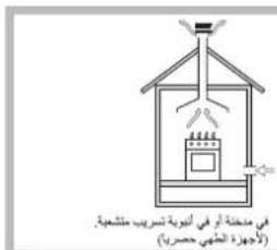
This appliance can be installed and used only in rooms with continuous ventilation in accordance with the applicable regulations. The following requirements must be observed:
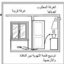
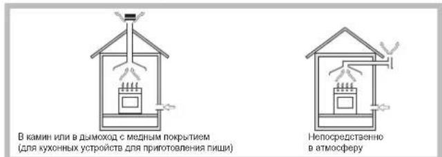
The room must be equipped with an air extraction system, made in the form of a ventilation hood or electric fan, which automatically turns on each time the appliance is switched on.
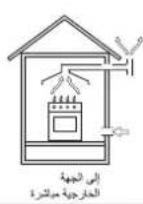
The room must be equipped with a system that ensures an adequate air supply for proper combustion. The air flow required for combustion must be no less than 2 m³/h per kW of installed power.
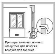
The air intake must be located directly outside, through an air duct with a cross-section of at least 100 cm² and a diameter that prevents accidental clogging.
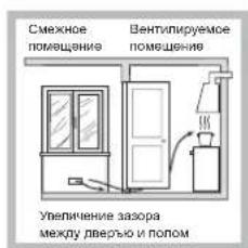
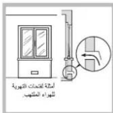
The air intake can be carried out from adjacent rooms equipped with ventilation openings communicating with the street, as described above, provided that these are not common areas of the building, fire-hazardous rooms, or bathrooms.
Liquefied gas propane-butane is heavier than air and therefore accumulates at the bottom. Therefore, in rooms where
cylinders with LPG (liquefied petroleum gas) are installed, ventilation openings must be provided at the bottom, communicating with the street, to allow the removal of possible gas leaks. Therefore, LPG cylinders must be emptied or remain hermetically sealed; they must not be placed or stored in underground rooms or storage areas (basements, etc.). Only one cylinder should be kept in the room, positioned so that it is not exposed to direct heat sources (stoves, fireplaces, etc.) that could heat the cylinder above 50°C.
Built-in installation
For built-in installation, the following precautions must be observed:
Kitchen elements placed next to the hob, whose height exceeds the level of the burner, must be at a distance of at least 200 mm from the edge of the burner. The hood must be installed in accordance with the hood's instruction manual and in any case at a height of at least 650 mm from the hob (see figure). Place wall cabinets adjacent to the hood at a height of at least 420 mm from the work surface of the kitchen (see figure).
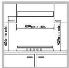
If the hob is installed under a wall cabinet, the latter must be at a height of at least 700 mm from the hob.
The dimensions of the kitchen element must correspond to the figure. The fixing kit includes fixing hooks for securing the hob to the kitchen work surface with a thickness of 20 to 40 mm. For reliable fixing of the hob, it is recommended to use all the supplied hooks.
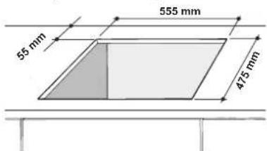
Before installation, remove the grilles and burner from the hob, turn it over, being careful not to damage the thermocouples and spark plugs.
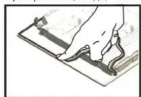
Install the supplied gasket around the outer perimeter of the hob to prevent air or water ingress (see diagram).
MOUNTING OF HOOK FOR SUPPORTING BARS H=20mm MOUNTING OF HOOK FOR SUPPORTING BARS H=30mm
RU
Front

Mounting of hook for supporting bars H=40mm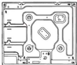
Install the hooks from the "Accessories" kit.
If the cooker hood is not installed above the built-in flue, it is necessary to install a deflector plate as insulation. This plate must be installed at a distance of no less than 20 mm from the lower part of the cooker hood.
Ventilation
To ensure proper ventilation, it is necessary to remove the panel or the hinged element. It is recommended to install the flue on two wooden blocks or on a solid base with an opening of at least 45 x 560 mm (see drawing).
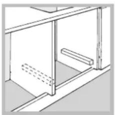
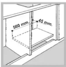
If the cooker hood is installed above the built-in flue, it is not equipped with additional ventilation devices. For proper ventilation inside the hinged element, it is necessary to make ventilation openings for air circulation (see drawing).
Electrical connection
Cooker hoods equipped with a three-phase power cable are designed to operate with alternating current with the voltage and frequency indicated on the rating plate (located at the bottom of the cooker hood). The ground wire of the power cable is yellow-green. In case of installing the cooker hood above the built-in flue, the electrical connection of the cooker hood and the flue must be done separately and in compliance with safety regulations, as well as for easy removal of the flue.
Connection to the power supply
Install a standardized plug on the power cable, designed for the load indicated on the rating plate. In case of
direct connection to the power supply, between the appliance and the network it is necessary to install a multi-pole switch with a minimum contact opening of 3 mm, designed for the given load and in accordance with current regulations (the switch must not break the ground wire). The power cable must be positioned in such a way that its temperature does not exceed the ambient temperature by more than 50°C.
The electrician is responsible for the correct connection and insulation of the electrical network and for compliance with safety regulations.
Before connecting the appliance to the power supply, check the following:
- The socket must be connected to the ground and comply with regulations;
- The power socket must be designed for the maximum power consumption of the appliance, as indicated in the technical data table;
- The frequency and voltage of the network must correspond to the electrical data of the appliance; the power socket must be compatible with the plug of the appliance. Otherwise, replace the socket or the plug; do not use extension cords or adapters.
The appliance must be installed in such a way that the electrical cable and the socket are easily accessible. The electrical cable must not be twisted or kinked. Regularly check the condition of the electrical cables and, if necessary, have them replaced only by authorized technicians (see Technical Service). The manufacturer is not responsible for the consequences of failure to comply with the above requirements.
Connection to the gas supply
This appliance may be installed and used only in rooms with permanent ventilation in accordance with current regulations, and only after checking that the appliance is suitable for the type of gas to which it will be connected. In case of mismatch, perform the operations described in the paragraph "Adjustment for different types of gas". If using liquefied gas from a cylinder, use pressure regulators that comply with current standards and the latest amendments.
For reliable operation, rational use of energy, and a longer service life of the electrical appliance, check that the gas supply pressure corresponds to the values indicated in Table 1 "Characteristics of gas burners and nozzles".
Connection using a rigid pipe (copper or steel). The connection to the gas supply must not exert any load on the appliance.
The gas supply pipe on the appliance has a rotating end "L" with a gasket. If necessary, turn the end; be sure to replace the gasket (supplied with the appliance). The gas supply pipe on the appliance has a cylindrical external thread 1/2 gas.
Connection using a flexible stainless steel pipe with thick walls and threaded connections.
The gas supply pipe on the appliance has a cylindrical external thread 1/2 gas.
Connection of such hoses must be done in such a way that their length or maximum extension does not exceed 2000 mm. After connection, check that the metal flexible hose does not touch moving parts and is not compressed.
Use exclusively pipes that comply with the standard, and sealing gaskets that comply with current state regulations.
Checking the seals
After completing the connection, check the tightness of all pipe connections using soapy water, but never with a flame.
Preparation for different types of gas
If the appliance is intended for a gas different from the one for which it was originally designed (indicated on the rating plate on the upper part of the appliance or on the packaging), it is necessary to replace the nozzles and burners as follows:
1. Remove the support grids from the burner and take out the burners from their seats. 2. Unscrew the nozzles using a 7 mm wrench and replace them with nozzles designed for the new type of gas (see Table 1 "Characteristics of burners and nozzles"). 3. Reassemble the parts in their places, performing the operations in reverse order. 4. After completing the operation, replace the old rating plate with a new one corresponding to the new type of gas used. The rating plate can be ordered from our Technical Service Centers.
Peylra nepBvHoro Bo3yxa KOnfopok
KoHcpKn He HyKaTcB KaKoI-Nb60peyIaIe IepBnuHoro Bo3dyxa.
HencnpaBHOCTN MeToDbI INX
yctpaHnna
Ecnn Baw xonodnBnHKe paobotaet. PpeJe yem o6paTntbCBAeHT CpBnCHOrO 06cIyKnBaHn, npOBepbTe, moXHO nYcTpaHnTB HeNCnPabHOCTb, nCIOJIb3yra peKOMeHaaun, npNBedeHHbE B CneIyHOeM nepeueHe.
KoHOpka He 3axraeTc, INI INaM rOpNT HepaBHomePHO.
BbipnoBepnJnI:
ΦOpCyHKn Ra3OBoK KOHΦopKn 3aOpPINcB. Bce cbeMHbIy aactn KOHOpKn DoXhBi 6blTb yCTaHOBJIeHbI npabmblHo. CKB03Hn pIaOM cra30BOB BapOHyo nAHeIbIO.
B MoDJIaX BapOuHoi NaHei, OChaUeHHbIX 3aUHTbIM yCTpoIcTBOM, KOHΦOPKa 3aropaeTcN cpa3y rachET.
Y6eDNTecbBTOM,HTO:
PykoTka KOHΦopKn HaxaTa He do ynopa. PykoTka 6bIa Haxata B TeueHne BpeMeHn, HeoctatoHoro dIy BKIOUeHn 3aunTHoro ycToCTBA. - 3acopehbl φopcyhkn razoboy KOHφopkn, pacnoIookeHHbIe HapotnB 3aunTHoro yCTPOINCTBa.
KoHΦopka rachET B NOJoxKeHH MaIoro PJIaMeHN.
Y6eNTecbBTOM,HTO:
3acopehbl OTBepTnna noaunra3b KoHdoppe. CKB03Hn pIaOM c rA3OBB BapOHO nAHeJIbIO. - HenpabunbHo OtperynnpoBaHo MHHMaIbHoe nIaM.
Hecta6nIbHbIe kAcTpOJI
- The pan must be perfectly flat. The pan must be installed in the center of the gas or electric burner.
- The support grates on the burner are installed incorrectly.
Oven
The oven door gasket is worn or damaged. If the oven door gasket is damaged, it must be replaced before using the appliance. Contact the service center for repair. The oven door must not be used if it is damaged.
Oven operation
Before using the oven, remove all packaging materials. Remove the protective film from the oven door and the oven interior (see "Cleaning and Maintenance"). Do not use the oven if the door gasket is damaged. If the oven door is damaged, contact the service center or a qualified technician for repair. Do not place heavy objects on the open oven door. The following precautions must be observed: - When opening the oven door, be careful not to touch the hot surfaces. The oven door may be hot when the oven is in use.
Before using the oven for the first time, it must be heated empty for at least 2 hours at a temperature of 200°C.
During the first use, some smoke and odor may be emitted; this is normal and will disappear after a few uses.
Therefore, if the oven is not used for a long time, it is recommended to heat it empty as described above. However, this should not be done too often, as it may damage the oven.
If the gas supply is interrupted, turn off the gas. If the gas supply is interrupted, the gas valves must be closed. If the gas supply is interrupted, do not attempt to light the burner. If the gas supply is interrupted, do not use the appliance. If the gas supply is interrupted, contact the gas company or a qualified technician. If the gas supply is interrupted, do not use the appliance until the gas supply is restored.
Oven operation
Safety instructions for using the oven
When installing the oven, the distance between the oven and the wall must be at least 200 mm. If the oven is installed near a wall, the distance must be at least 650 mm (see figure). The distance between the oven and the floor must be at least 420 mm (see figure).
If the oven is installed near a wall, the distance between the oven and the wall must be at least 700 mm (see figure).
Opahaty kybcI cypeTte KepcTeiReH anWeMdepre He 6Olyb Tmic.
YctIHIN KAIbIbIbIbI 20 MeH 40 MM apacbIdaI bI WkaTapra NmTaHbI opHAtyMaMkiHik 6epTeH 6ekit yImeKtepi kAmTacB3 etInre. PInIta WkaF yCtHeMbIKan 6ekitireHHe Ke3 JeKtkiyyin 6apbIK imMeKtepi naDanahyKepe.
OpHaTnac 6pybH nIITaDAn TOpnap MeH OTbIKTapdbI bIbIapBIn aBIn, OHbI aydapbIHbI. TePMoKyTpAmp HeY TaHDbIPbIbTApDbI 3akBIMdaI anImAhbI3.
Aya, binnan xhe cy etneiy yuin Kypblnfbimen 6ipre 6epinren Tbifbl3aflbwtapdbnnlntahbH cbptkbXneKTEpihe kondaHbHb3 (cyprrkapaHb3).Dpybcxxyuin TbIf3danaTbH6ETep Ta3a, kprak ekehHe xhe man xok ekenhe Ke3
Ketki3iHj3.
Imekri 6ekiry cb36acbl
Imek ophbl wkaq yctihin Imek ophbl wkaq yctih H KaBHdbfH 20mm Ywih KaBHdbfbH 30mm Ywih
Andbi
ImekOpHbI WkaFyCTHHApTbI KaJIbHdbIbH H=40MM yUH
!"Kepek-kaapakTap"opamacbIaIbIiIMMeKTePdi KOnIaHbIbI3.
-Пита eндірінг的新 yctihe ophaылmarан kafdяда, okшaynay yuH araa taktahbl ophaTy kaxet. Obl Питаын actbHfbl kafbHaH KEM dereHne 20 MM apa kaabkTBkTApO anactbIPy Kepek.
Xeneta
Tnicti kennetdyin ophTabnfahbH TeKcpey yuiu HkaftbH apTkbl Ka6bpFcbH anbIn TactayKaKet. NeuTI eki aafw TaTaNHa Hemece KEMHe 45 x 560 MM auBik typAH teric kepe opHaNactbipy CbHbnaDbl (cb36aHbKapaHb3).
Erepnicipy naHeni eKahdaincanbHdaTaTbHKeJeTeKiXJKoCbIMua 6epinre HdyoxOBka KafbHbYcTIe opHaNactbIpaIca iKi acy 3IeMeHTHHiTHnTiCTy KeJeDey yuH apHaBlyaaya aHaHbMbH pettey yuH Teickacay Kepek (Cb36aHbKapa).
3NeKtp KyaTbHa Kocy
Connect the device to the electrical network in accordance with the technical passport and the rules for the safe operation of electrical installations (the passport must be kept in a safe place).
The device must be grounded. If the paint coating is damaged at the grounding point, the grounding conductor and the paint must be cleaned and the grounding must be restored separately.
Connecting to the electrical network
Connect the device to the electrical network in accordance with the technical passport and the rules for the safe operation of electrical installations. If the device is connected to the network, the distance between the device and the wall must be at least 3 mm. The device must be connected to the network through a standard socket, and the grounding must be done in accordance with the regulations. The device must be installed in a place where the ambient temperature does not exceed 50°C.
Protect the device from direct contact with water and from accidental mechanical damage.
Before connecting the device, check the following:
- The socket must be grounded and comply with the regulations. The socket must be connected to the maximum allowable current according to the technical passport. The device must be connected to the electrical network through a standard socket;
- The socket must be grounded and comply with the regulations. If not, replace the socket or the plug; do not touch the current-carrying parts and the plug with wet hands. The device must be installed at a distance of at least 3 mm from the wall. The device must not be installed in a damp or dusty place. If the device is damaged, do not use it and contact a qualified technician for repair. The device must be disconnected from the power supply before any maintenance.
Connecting to the gas pipeline
The gas pipeline must be laid in accordance with the requirements of the regulatory documents in force in the Republic of Kazakhstan, and the possibility of connecting to the gas pipeline must be provided (see the section on connecting to the gas pipeline). The gas pipeline laid in the ground must be laid in accordance with the requirements of the regulatory documents in force in the Republic of Kazakhstan. If the gas pipeline is laid in the ground, the following must be done: the welded joints must be checked and the insulation must be checked.
The energy service must be performed in accordance with the requirements of the regulatory documents in force in the Republic of Kazakhstan, and the gas pipeline must be connected to the gas pipeline in accordance with the requirements of the regulatory documents in force in the Republic of Kazakhstan.
Laying the gas pipeline with a pipe (with a diameter of 100 mm)
The gas pipeline must be laid with a slope. When laying the gas pipeline, the slope must be at least 0.003. If the slope is not provided, the gas pipeline must be laid with a slope of at least 0.003 (see the section on laying the gas pipeline). The gas pipeline must be laid with a slope of at least 0.003.
The gas pipeline must be laid with a slope of at least 0.003.
The gas pipeline must be laid with a slope of at least 0.003.
When laying the gas pipeline, the maximum depth of the gas pipeline must be at least 2000 mm. After laying the gas pipeline, the gas pipeline must be tested for strength and tightness.
The gas pipeline must be laid in accordance with the requirements of the regulatory documents in force in the Republic of Kazakhstan.
Testing the gas pipeline
After laying the gas pipeline, all joints must be checked for tightness, and the gas pipeline must be tested for strength and tightness.
Connecting the gas pipeline to the gas pipeline
The gas pipeline must be connected to the gas pipeline in accordance with the requirements of the regulatory documents in force in the Republic of Kazakhstan. The connection must be made in accordance with the requirements of the regulatory documents in force in the Republic of Kazakhstan.
- The gas pipeline must be laid in accordance with the requirements of the regulatory documents in force in the Republic of Kazakhstan.
- The gas pipeline must be laid in accordance with the requirements of the regulatory documents in force in the Republic of Kazakhstan.
- Do not use other containers for storing these gases.
- After using the gas cylinder, close the valve tightly. Do not use the cylinder if the valve is damaged. Contact the manufacturer or service center for repairs. Do not attempt to repair the cylinder yourself. Minimum pressure 1. Do not expose the cylinder to temperatures above 50°C;
- Do not remove the cylinder valve, do not attempt to repair it yourself, or replace it with a valve from another cylinder.
- If the cylinder is not used for a long time, close the valve tightly and store it in a well-ventilated area, away from heat sources and direct sunlight.
- Some cylinders are equipped with a thermal fuse. If the cylinder is exposed to high temperatures, the fuse will activate and release the gas, so do not expose the cylinder to high temperatures.
- After repairing the cylinder, check the valves for leaks or replace them if necessary.
If the cylinder is damaged, do not use it and contact the manufacturer.
After this period, do not use the cylinder with the new gas type; replace it with a cylinder designed for the new gas type. Cylinders should be replaced at the manufacturer's service center.
If the gas pressure is too high or too low, adjust the pressure regulator accordingly (see instructions for adjustment).
| ДЕPEKTEP KECTECI | |
| 3нектР ОсьлбIMдары | Деректр КecTeciH KapaHbI3 |
| CE | Бул КрынгБу Eypona ЭкоНомпкалыКауыIMдасыТыньи Keleci HucKayларыHa сayKeledi: -2006 КрынгБу 12-cayipderi 2006/95/EC (ТеменКерney Тураны) ДерекТиВасы Көне Oдан Көнir TyэтУнр -2004 КрынгБу 15-жentOKсанданы 2004/108/EC(ЗдекТрмогинтik УлесимдінгТураны) ДерекТиВасы Көнe Oдан Көнir TyэтУнр -1993 КрынгБу 22-шindederi 93/68/EEC ДерекТиВасы Көнe Oдан Көнir TyэтУнр. -2009 Крыньн 30- karpaшасыТураны -2009/142/EC (ras Tураны) ДерекТиВасы Көнe Oдан Көнir TyэтУнр. -2012/19/EU Көнe Oдан Көнir TyэтУнр. |
Gas and cylinder specifications
| 1-keCTe | Сультынган ra3 | Табигу ra3 | |||||||
| Жанарсы Диаметр | Жыл实用性 м对人体有害性 KBТ (p.c.s.) Hom. Kaick. | Байпас 1/100 (MM) | Форсунka 1/100 (MM)(MM) | Шьгын* r/car. | Форсунka 1/100 | Шьгын* r/car. | |||
| Жылдам (R) | 94 | 3.00 | 0.70 | 39 | 87 | 218 | 214 | 128 | 286 |
| Жарсылай жылдам (S) | 69 | 1.90 | 0.40 | 28 | 70 | 138 | 136 | 104 | 181 |
| Косымба (A) | 46 | 1.00 | 0.40 | 28 | 52 | 73 | 71 | 76 | 95 |
| Өткizу кizсímыhomina DLbI | Mбap) | 28-30 | 37 | 20 | |||||
| 20 | 25 | 17 | |||||||
| 35 | 45 | 25 | |||||||
- At 15°C and 1013.25 mbar - Propane gas **Propane P.C.S. = 50.37 MJ/kg *** Butane P.C.S. = 49.47 MJ/kg
Table P.C.S. = 37.78 MJ/m³
PIM 640AS
PIM 640A
Kocy XəHe paɪdaɪaɪny
!Tnicti ras OTtbfbHbH OphbAp6ip TyTkana Kepcetireh.
Taa OTtbikTapbl
Op6ip OTbIKTb Tnicti Backapy TyKacbHbH Kemerineh TEmenderi napametprpeDih 6pihe peTeyre 50ana:
- Uwipyni

EHxofapbl

EH TEMEH
KaHApBnapDbH 6ipH XaHbIpy yuiH, XaHaPbHbH JxahbHa XaHbITypfAH cipihke He OTbIK anapbIn, dAn con yaKbTTA Tnicti TyTKaHbI 6acbl, MaKcImaIdbI petTreyre deHH 6paHbI3.
KaHApfkiayinc3ik KpybIfbcImeH Ka6blkTaHaftbKaTah,ABTomATBtI KpybIFraKb3dbpyyiwOTbXaHbInTypfAHyndeCaTayFMyMkhDikBepy yuH TTKaHbIwamamen2-3cekyHidiwHe6acbinTypyKepek.
Tytaty Tymeci 6ap moenbdepni naananaHraeKe3e, andbimeh ra3
OTbIKTapbIHb TYIcMecH (THaHbAcBImeH KepCetInreH) bacIn, oah KeHH TnictyTKaHbI aRbHa deHH BacIn, OHb carat tinihe KapcbiBaftTa eH XOFapfI npamETpre 6py apkblb KaKeTTI OTbIKTb JkaHdbIpblH3.
!KaJIbH6aIKayCbI3eUipince,6ackapy tyTKacBIn eUipin3 de,ohb KaITadaH KaKnac 6byh KEM dereHe 1MHHT KyTih3.
OTtbkTb ewipy yuih tykaHb cafat tini 6aftbHa da ToktaHa 6ypbHb3 ("" no3nncbHa JxetKeHue).
- OPERATING INSTRUCTIONS HOB
- OPERATING MANUAL
- VARIANT
- PAINDAHNY HYCKAYIBIFBL
- NTNTA
- IT
- AVVERTENZE
- WARNINGS
- ASSISTANCE
- PROVIDE THEM WITH
- RU
- MAINTENANCE SERVICE
- KZ
- KOMEK
- IMPORTANT INFORMATION
- DESCRIPTION OF THE APPLIANCE
- OVERALL VIEW
- FR
- BE
- NL
- POSITIONING
- FITTING THE APPLIANCE
- HOOK FASTENING DIAGRAM
- FRONT
- GB
- VENTILATION
- ELECTRICAL CONNECTION
- CONNECTING THE SUPPLY CABLE TO THE MAINS
- GAS CONNECTION
- CONNECTION WITH A RIGID PIPE (COPPER OR STEEL)
- CONNECTING A FLEXIBLE JOINTLESS STAINLESS STEEL PIPE TO A THREADED ATTACHMENT
- CHECKING THE TIGHTNESS OF THE CONNECTION
- ADAPTING TO DIFFERENT TYPES OF GAS
- BURNER AND NOZZLE SPECIFICATIONS
- START-UP AND USE
- GAS BURNERS
- PRACTICAL ADVICE ON USING THE BURNERS
- PRECAUTIONS AND TIPS
- GENERAL SAFETY
- DISPOSAL
- RESPECTING AND CONSERVING THE ENVIRONMENT
- MAINTENANCE AND CARE
- SWITCHING THE APPLIANCE OFF
- CLEANING THE APPLIANCE
- GAS TAP MAINTENANCE
- TROUBLESHOOTING
- THE BURNER DOES NOT LIGHT OR THE FLAME IS NOT EVEN AROUND THE BURNER
- THE FLAME DIES IN MODELS WITH A SAFETY DEVICE
- THE BURNER DOES NOT REMAIN LIT WHEN SET TO MINIMUM
- THE COOKWARE IS UNSTABLE
- INSTALLATION
- LOCATION
- BUILT-IN INSTALLATION
- CONNECTION TO THE POWER SUPPLY
- CONNECTION TO THE GAS SUPPLY
- CHECKING THE SEALS
- PREPARATION FOR DIFFERENT TYPES OF GAS
- HENCNPABHOCTN METODBI INX
- YCTPAHNNA
- KOHOPKA HE 3AXRAETC, INI INAM ROPNT HEPABHOMEPHO
- B MODJIAX BAPOUHOI NAHEI, OCHAUEHHBIX 3AUHTBIM YCTPOICTBOM, KOHΦOPKA 3AROPAETCN CPA3Y RACHET
- KOHΦOPKA RACHET B NOJOXKEHH MAIORO PJIAMEHN
- HECTA6NIBHBIE KACTPOJI
- OVEN
- OVEN OPERATION
- IMEKRI 6EKIRY CB36ACBL
- ANDBI
- XENETA
- NEKTP KYATBHA KOCY
- CONNECTING TO THE ELECTRICAL NETWORK
- CONNECTING TO THE GAS PIPELINE
- LAYING THE GAS PIPELINE WITH A PIPE (WITH A DIAMETER OF 100 MM)
- THE GAS PIPELINE MUST BE LAID WITH A SLOPE OF AT LEAST
- TESTING THE GAS PIPELINE
- CONNECTING THE GAS PIPELINE TO THE GAS PIPELINE
- GAS AND CYLINDER SPECIFICATIONS
- KOCY XƏHE PAꞮDAꞮAꞮNY
- TAA OTTBIKTAPBL
Brand : INDESIT
Model : PIM 640 AS (BK)
Category : Cooker