AN65AG2 - Wall mount SHARP - Free user manual and instructions
Find the device manual for free AN65AG2 SHARP in PDF.
| Product Type | Wall mount for LCD TV |
| Brand | Sharp |
| Model | AN65AG2 |
| Compatibility | Sharp TVs LC-65XS1, LC-65XS1U, LC-65XS1E, LC-65XS1RU, LC-65XS1X, LC-65XS1M, LCD-65XS1A |
| Maximum supported weight | 64.5 kg (TV + mount) |
| Material | Steel (sheet thickness: 1.6 to 2 mm depending on part) |
| Dimensions of base brackets (assembled) | 520 mm (width) x 340 mm (height) approx. |
| Dimensions of TV mounting bars | 52 mm x 621.5 mm |
| Number of wall mounting points | 20 screws (not included, M6 diameter recommended) |
| Screws provided | Screw A (M5x6mm) x2, Screw B (M8x14mm) x4, Screw C (M6x10mm) x6, Screw D (M4x6mm) x4, Washers E x2 |
| Installation | By a qualified installer only; two persons required |
| Wall mounting | Standard M6 screws (not included); wall must support >64.5 kg |
| Maintenance | Clean with a soft dry cloth; do not use abrasive products |
| Safety | Do not modify parts; follow instructions to prevent falls |
| Repairability | Spare parts available from manufacturer; no user repair |
| Warranty | Refer to manufacturer's terms |
| Downloadable manual | Yes (PDF format, 50 pages) |
Frequently Asked Questions - AN65AG2 SHARP
User questions about AN65AG2 SHARP
0 question about this device. Answer the ones you know or ask your own.
Ask a new question about this device
Download the instructions for your Wall mount in PDF format for free! Find your manual AN65AG2 - SHARP and take your electronic device back in hand. On this page are published all the documents necessary for the use of your device. AN65AG2 by SHARP.
USER MANUAL AN65AG2 SHARP
LCD Color TV Wall-Mount Bracket
natural_image
Line drawing of a flat-screen monitor with a grid layout and control panel (no text or symbols)取扱説明書
OPERATION MANUAL
MODE D'EMPLOI
BEDIENUNGSANLEITUNG
MANUAL DE MANEJO
使用说明书
CAUTION: This product (SHARP, AN-65AG2) is only to be used for the SHARP LCD TV as follows. Using the bracket for another product could cause an accident.
To Ensure Safe and Correct Use ......E-1
Outside Dimension Drawing ....E-2
Package Contents ......E-3
Attaching the Based Brackets to the Wall ......E-4
Attaching the Brackets to the LCD Color TV ......E-5
Installing the LCD Color TV on the Wall ......E-6
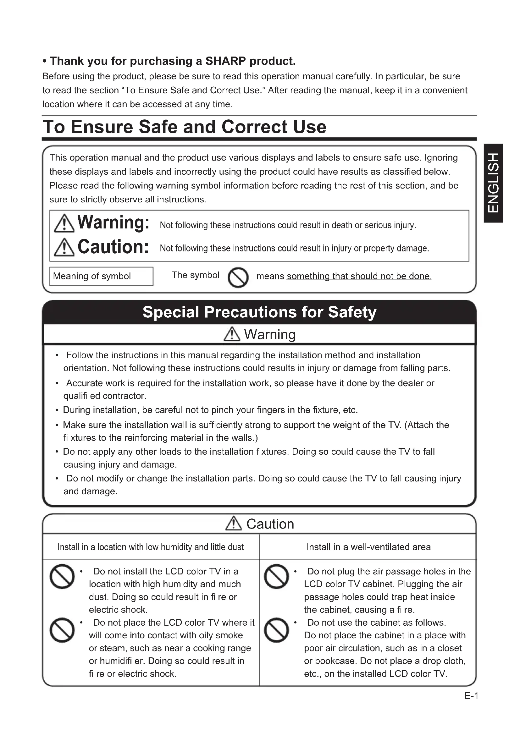
- Thank you for purchasing a SHARP product.
Before using the product, please be sure to read this operation manual carefully. In particular, be sure to read the section “To Ensure Safe and Correct Use.” After reading the manual, keep it in a convenient location where it can be accessed at any time.
To Ensure Safe and Correct Use
This operation manual and the product use various displays and labels to ensure safe use. Ignoring these displays and labels and incorrectly using the product could have results as classified below. Please read the following warning symbol information before reading the rest of this section, and be sure to strictly observe all instructions.

Warning:
Not following these instructions could result in death or serious injury.

Caution:
Not following these instructions could result in injury or property damage.
Meaning of symbol
The symbol

means something that should not be done.
Special Precautions for Safety

Warning
- Follow the instructions in this manual regarding the installation method and installation orientation. Not following these instructions could results in injury or damage from falling parts.
- Accurate work is required for the installation work, so please have it done by the dealer or qualified contractor.
- During installation, be careful not to pinch your fingers in the fixture, etc.
- Make sure the installation wall is sufficiently strong to support the weight of the TV. (Attach the fi xtures to the reinforcing material in the walls.)
- Do not apply any other loads to the installation fixtures. Doing so could cause the TV to fall causing injury and damage.
- Do not modify or change the installation parts. Doing so could cause the TV to fall causing injury and damage.

Caution
Install in a location with low humidity and little dust

- Do not install the LCD color TV in a location with high humidity and much dust. Doing so could result in fire or electric shock.

- Do not place the LCD color TV where it will come into contact with oily smoke or steam, such as near a cooking range or humidifi er. Doing so could result in fi re or electric shock.

- Do not plug the air passage holes in the LCD color TV cabinet. Plugging the air passage holes could trap heat inside the cabinet, causing a fire.

- Do not use the cabinet as follows. Do not place the cabinet in a place with poor air circulation, such as in a closet or bookcase. Do not place a drop cloth, etc., on the installed LCD color TV.
Please strictly observe the following.
Special skill is required to install the LCD color TV, so please have it installed by a contractor specializing in such installation. The customer should not attempt to install the TV. Sharp shall not be responsible for improper installation or any accidents, damage, or injury resulting from improper installation.
To the contractor
- To ensure the safety of the customer, conduct the design so that the strength of the installation location is sufficiently strong to support the weight of the LCD color TV and the wall-mount bracket.
- Be sure to use two or more people to conduct the work.
- The wall installation screws for the based brackets are not included with the fixtures. Select off-the-shelf screws that match the wall.
Outside Dimension Drawing
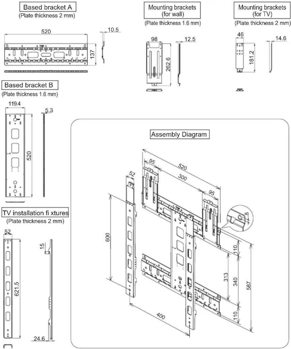
Units: mm
Package Contents
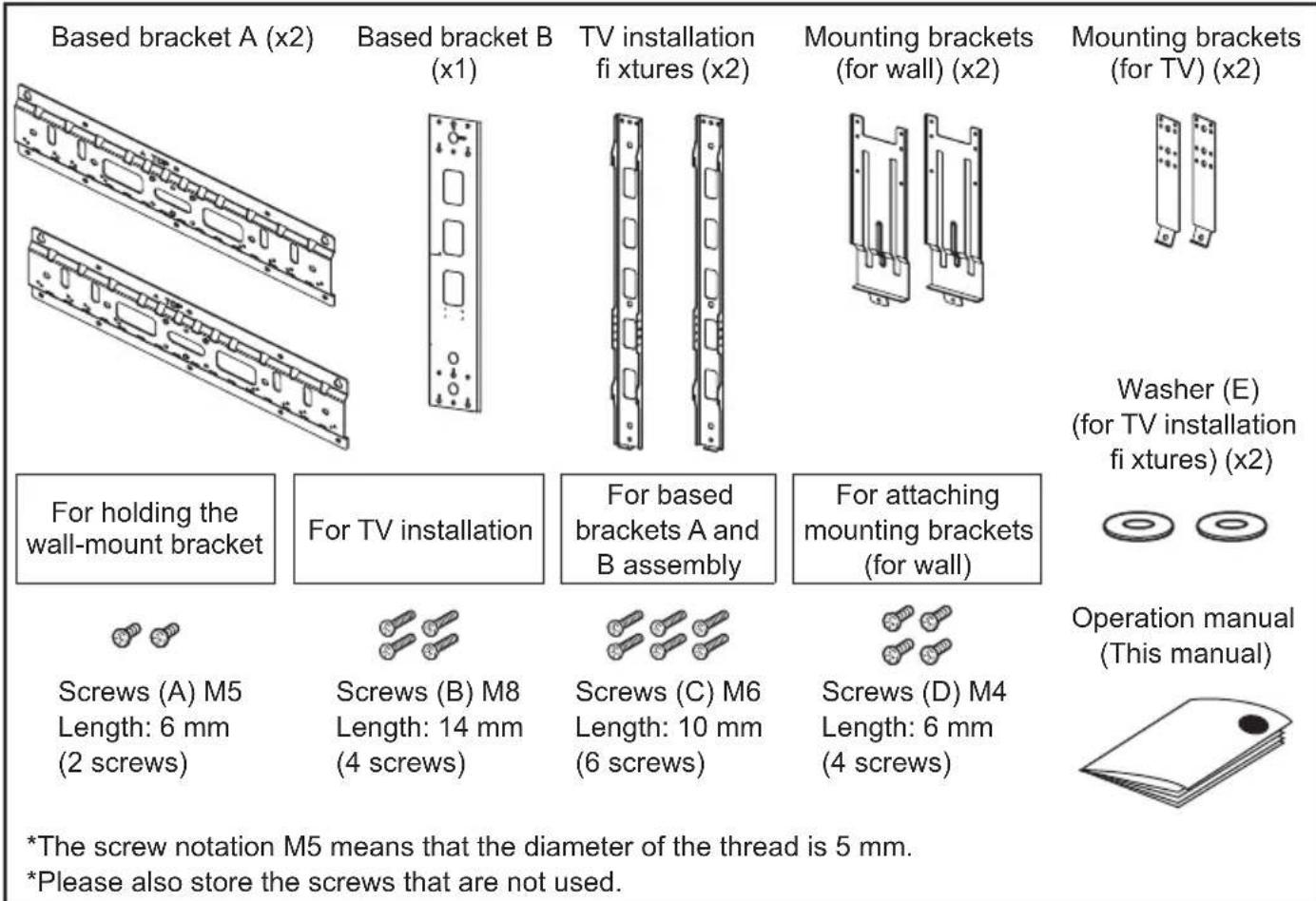
Please use the following
Installation location
• Wall installation screws (off-the-shelf screws, x20)
When installing the TV, be sure to consult with the dealer or qualified contractor.
- A plumb bob (or a washer on a string) - A pin, such as a thumbtack
- Cushion, soft cloths, etc. - Tools (Phillips head screw driver)
- LCD color TVs have a viewing angle (range in which the image can be viewed correctly). The best viewing position is from directly in front of the screen. Determine the TV installation location after taking into consideration the viewing posture, line of sight, and the visual and aural ranges.

- Sharp shall bear no responsibility for damages, etc., caused by the LCD color TV falling due to insufficient installation strength or improper installation.
Weight Table (Unit: kg. All values approximate.)
| Destination market | Model TV (without stand) Brackets Total | |||
| Japan LC-65 | XS1 59.5 5.0 64.5 | |||
| Except for Japan | LC-65XS1U 59.5 | 5.0 64.5 | ||
| LC-65XS1E 59.5 | 5.0 64.5 | |||
| LC-65XS1RU 59 | 5 5.0 64.5 | |||
| LC-65XS1X 59.5 | 5.0 64.5 | |||
| LC-65XS1M 59.5 | 5.0 64.5 | |||
| LCD-65XS1A 59 | 5 5.0 64.5 | |||
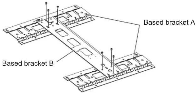
Attaching the Based Brackets to the Wall
1
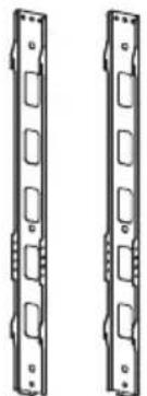
Assembling based brackets A and B
Assemble based brackets A and B as shown below, and use the 6 included screws (C) (M6, 10 mm) to fasten them together.
2
Determining a mounting location for the based brackets
Use the plumb bob (or washer on a string) prepared earlier to check that the based brackets are positioned vertically. Confirm vertical orientation using the vertical reference line on based bracket B, and use a pencil to mark the position of the two screw holes.
Adhesive tape
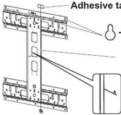
-shaped screw holes
Mark the wall using a pencil.
The edge of based bracket B is used as a reference line for determining horizontal and vertical orientation.
The letters and lines indicate the position of the center line of the screen for the LCD color TVs. Use them as guidelines for installation height.
A: LC-65XS1/LC-65XS1U/LC-65XS1E/ LC-65XS1RU/LC-65XS1X/LC-65XS1M/LCD-65XS1A
3
Temporarily attaching the screws
Remove the based brackets from the wall, and temporarily attach off-the-shelf screws (M6, 2 screws) in the screw hole locations marked on the wall. When doing so, ensure that the heads of the screws are at least 4 mm away from the wall to allow enough space for the based brackets to be attached. Hang the based brackets over the screws, and tighten the screws firmly after confirming that based brackets are not leaning to either side.
Use off-the-shelf screws (M6, 18 screws) to attach the remaining screw holes to the wall.
Attaching the Based Brackets to the Wall (Continued)
4
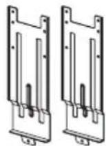
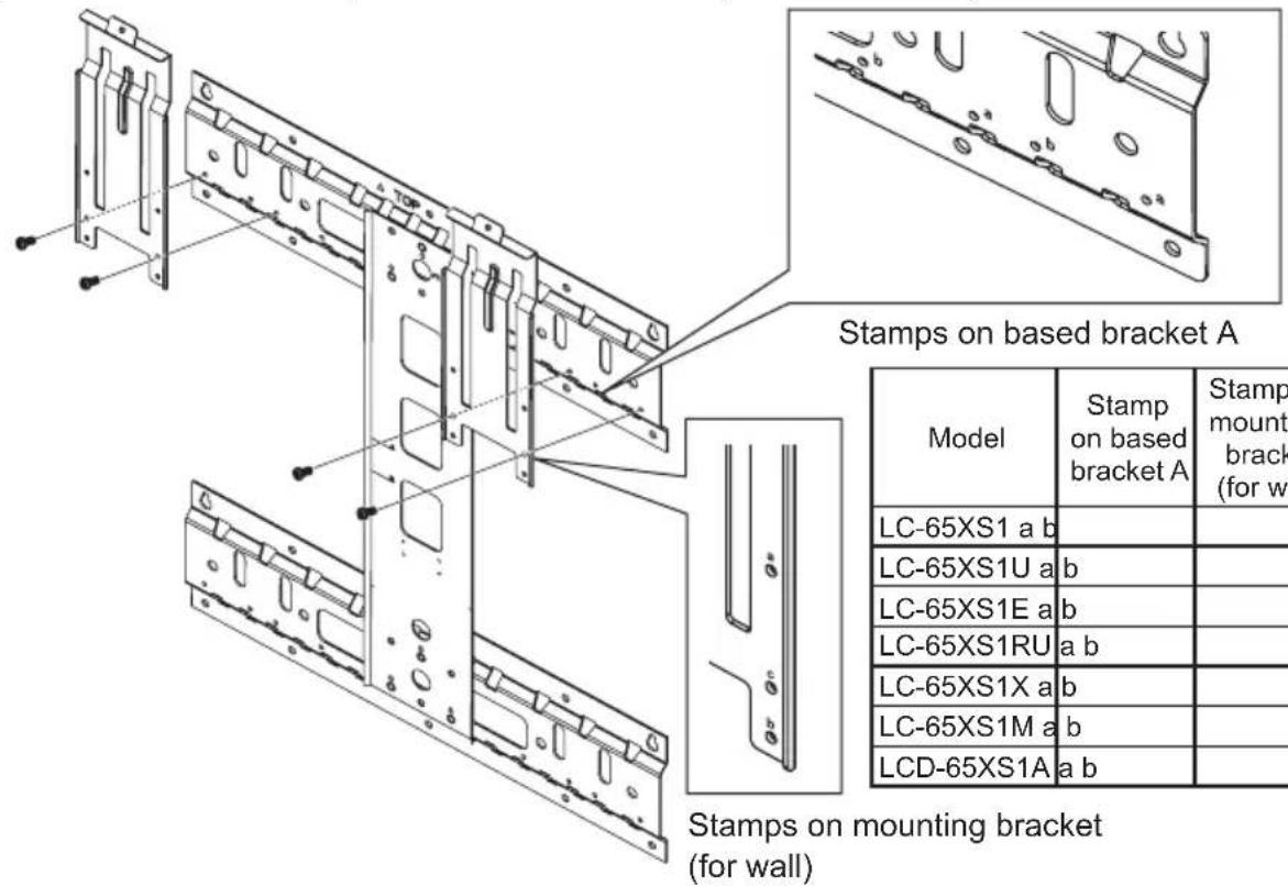
Attaching the mounting brackets (for wall) to the based brackets
Align the 4 attachment bracket screw holes on the based brackets and the mounting brackets (for wall) and attach them together using 4 screws (D) (M4, 6 mm). Bracket mounting positions differ according to LCD color TV model. (See table below.)
Attaching the Brackets to the LCD Color TV
1
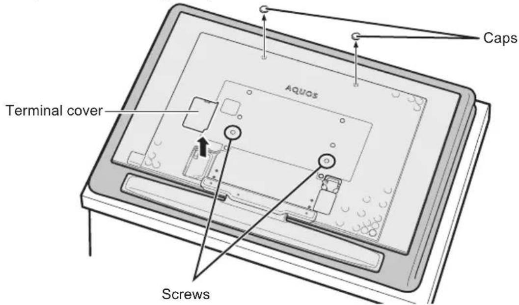
Remove the caps and the terminal cover from the back of the LCD color TV
Place the LCD color TV on a blanket or other thick, soft cloth, and remove the 2 caps indicated, 2 screws, and the terminal cover from the back. (Store the caps and screws in a safe place after removing them.)
2
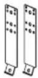
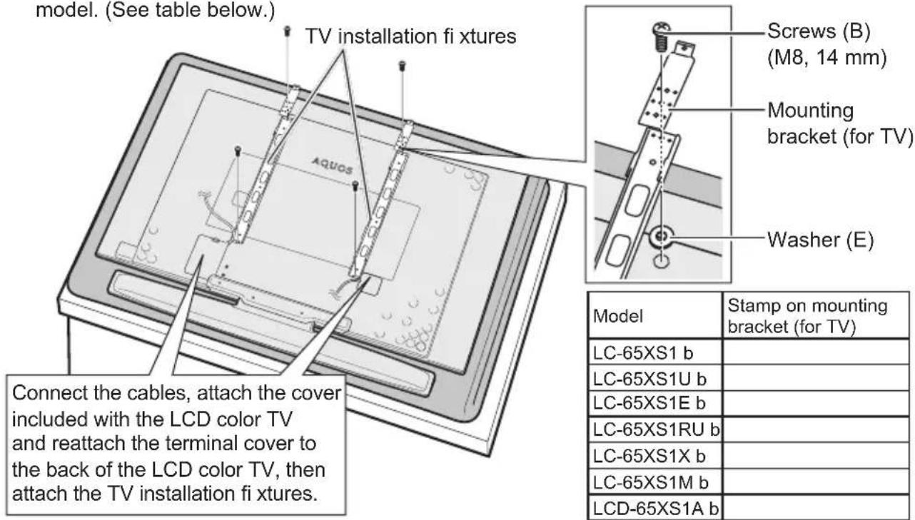
Tidying cables, and attaching the TV installation fi xtures and the mounting brackets (for TV) to the LCD color TV
Use 4 screws (B) (M8, 14 mm) to firmly attach the TV installation fixtures and the mounting brackets (for TV) to the back of the LCD color TV.
When doing so, be sure to attach the TV installation fixtures and the mounting brackets (for TV) in the configuration and direction indicated below.
The attachment position of the mounting brackets (for TV) differs according to LCD color TV model. (See table below.)
Installing the LCD Color TV on the Wall

- Be sure to use two or more people to mount the LCD color TV to the based brackets.
- Be sure to attach the TV to the brackets correctly. If you do not attach them correctly, the LCD color TV may fall and cause injury.
Mounting the LCD color TV on the wall and fastening screws
Insert the TV installation fixture hooks into the 4 triangular holes on based bracket A, and secure the top of the brackets using the 2 screws (A) (M5, 6 mm).
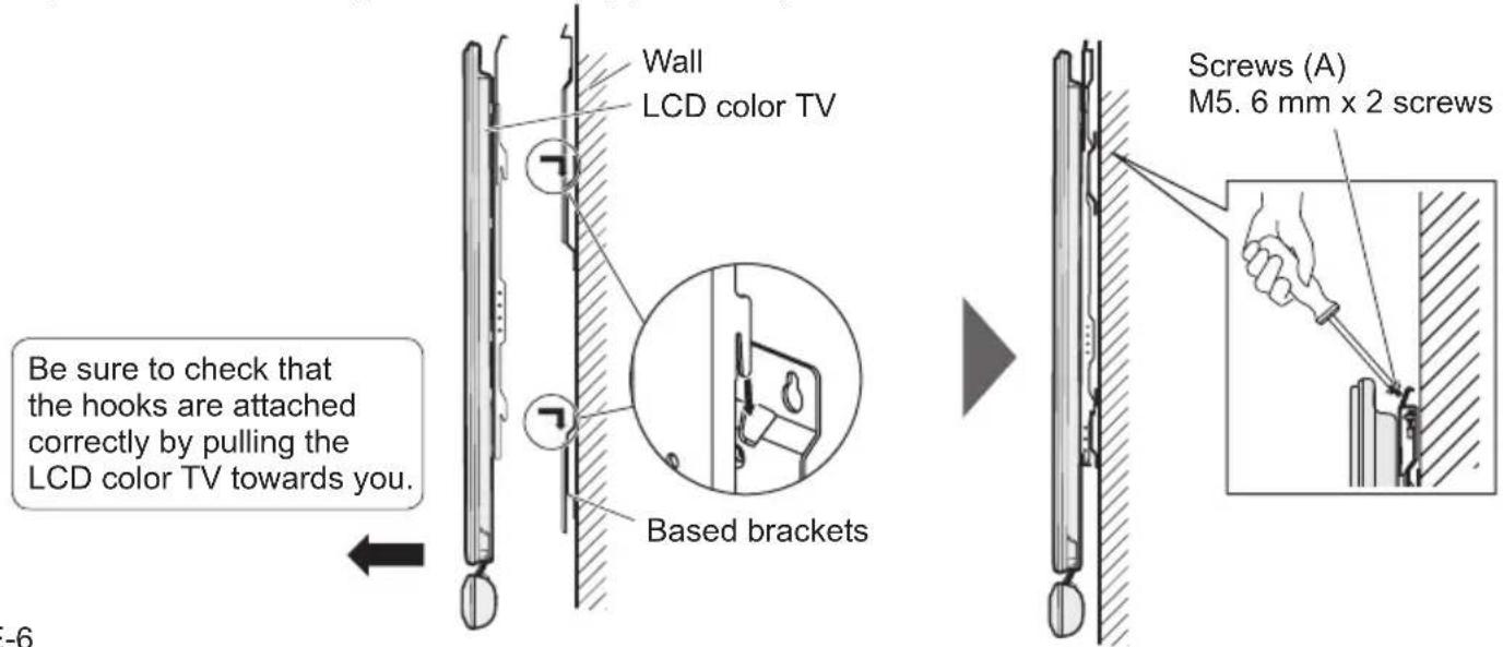
Table des matières
natural_image
Technical line drawing of two mechanical components with mounting holes and internal slots (no text or symbols)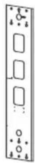
natural_image
Two identical mechanical component diagrams with rectangular cutouts and mounting holes (no text or symbols)