AN-65AG1 - Wall mount SHARP - Free user manual and instructions
Find the device manual for free AN-65AG1 SHARP in PDF.

| Product Type | Fixed TV Wall Mount |
| Brand | Sharp |
| Model | AN-65AG1 |
| Compatible Screen Size | 37 to 70 inches |
| Maximum Weight Capacity | 50 kg (110 lbs) |
| VESA Compatibility | 200x200 to 600x400 mm |
| Material | Cold rolled steel |
| Surface Finish | Powder coated matte black |
| Dimensions (W x H x D) | 730 x 420 x 50 mm |
| Product Weight | 3.2 kg |
| Tilt Range | 0 to 12 degrees forward |
| Level Adjustment | ±2 degrees after installation |
| Distance from Wall | 30 mm (minimum) |
| Installation | Professional installation recommended |
| Included Accessories | Mounting brackets, screws, anchors, level, manual |
| Warranty | 2 years limited |
| Cleaning Instructions | Wipe with dry or slightly damp cloth; no solvents |
| Safety Warning | Do not exceed weight limit; install on solid wall |
| Spare Parts Availability | Screws and anchors available as spare parts |
Frequently Asked Questions - AN-65AG1 SHARP
User questions about AN-65AG1 SHARP
0 question about this device. Answer the ones you know or ask your own.
Ask a new question about this device
Download the instructions for your Wall mount in PDF format for free! Find your manual AN-65AG1 - SHARP and take your electronic device back in hand. On this page are published all the documents necessary for the use of your device. AN-65AG1 by SHARP.
USER MANUAL AN-65AG1 SHARP
LCD Color TV Wall-Mount Bracket
natural_image
Illustration of a flat-screen monitor with a side clip, no text or symbols visible- 壁用金具取付ネジは同梱しておりませんので市販品をお求めください。
- The wall bracket mounting screws are not included with the product, so please separately purchase off-the-shelf screws.
- Les vis de fixation du support à base ne sont pas fournies avec le produit; veuillez donc acheter séparément des vis en vente dans le commerce.
• Die Wandhalter-Befestigungsschrauben sind nicht im Lieferumfang des Produkts enthalten. Besorgen Sie sich daher bitte im Handel erhältliche Schrauben. - Los tornillos de montaje de ménsula en la pared no vienen con el producto, compre los tornillos por separado en la tienda.
- 附属品中无墙用配件安装用螺丝,请另购市售品。
AN-65AG1
取扱説明書
OPERATION MANUAL
MODE D'EMPLOI
BEDIENUNGSANLEITUNG
MANUAL DE MANEJO
使用说明书
- Thank you for purchasing a SHARP product.
Before using the product, please be sure to read this operation manual carefully. In particular, be sure to read the section "To Ensure Safe and Correct Use." After reading the manual, keep it in a convenient location where it can be accessed at any time.
To Ensure Safe and Correct Use
This operation manual and the product use various displays and labels to ensure safe use. Ignoring these displays and labels and incorrectly using the product could have results as classified below. Please read the following warning symbol information before reading the rest of this section, and be sure to strictly observe all instructions.

Warning: Not following these instructions could result in death or serious injury.

Caution: Not following these instructions could result in injury or property damage.
Meaning of symbol
The symbol

means something that should not be done.
Special Precautions for Safety

Warning
- Follow the instructions in this manual regarding the installation method and installation orientation. Not following these instructions could results in injury or damage from falling parts.
- Accurate work is required for the installation work, so please have it done by the dealer or qualified contractor.
- During installation, be careful not to pinch your fingers in the fixture, etc.
- Make sure the installation wall is sufficiently strong to support the weight of the TV. (Attach the fixtures to the reinforcing material in the walls.)
- Do not apply any other loads to the installation fixtures. Doing so could cause the TV to fall causing injury and damage.
- Do not modify or change the installation parts. Doing so could cause the TV to fall causing injury and damage.

Caution
Install in a location with low humidity and little dust

- Do not install the LCD color TV in a location with high humidity and much dust. Doing so could result in fire or electric shock.

- Do not place the LCD color TV where it will come into contact with oily smoke or steam, such as near a cooking range or humidifier. Doing so could result in fire or electric shock.

- Do not plug the air passage holes in the LCD color TV cabinet. Plugging the air passage holes could trap heat inside the cabinet, causing a fire.

- Do not use the cabinet as follows. Do not place the cabinet in a place with poor air circulation, such as in a closet or bookcase. Do not place a drop cloth, etc., on the installed LCD color TV.
Please strictly observe the following.
Special skill is required to install the LCD color TV, so please have it installed by a contractor specializing in such installation. The customer should not attempt to install the TV. Sharp shall not be responsible for improper installation or any accidents, damage, or injury resulting from improper installation.
To the contractor
- To ensure the safety of the customer, conduct the design so that the strength of the installation location is sufficiently strong to support the weight of the LCD color TV and the wall-mount bracket.
- Be sure to use two or more people to conduct the work.
- The wall installation screws for the wall-mount brackets are not included with the fixtures. Select off-the-shelf screws that match the wall.
Outside dimension drawing
Base bracket
(Mark A: At a height at the center of the LC-65GE1 screen)
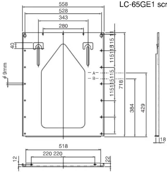
Wall-mount bracket
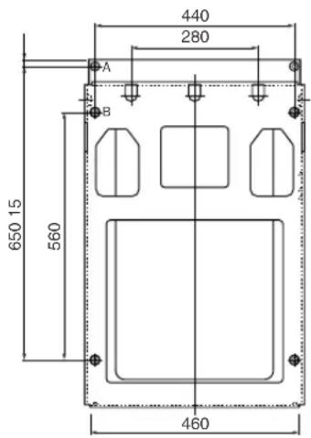
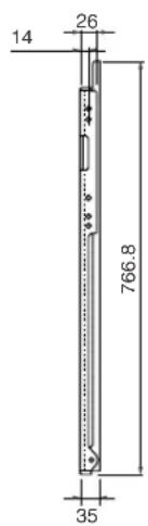
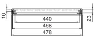
Unit: mm
Accessories packaged with the TV
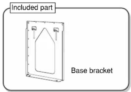
Base bracket: 1 Wall-mount bracket: 1
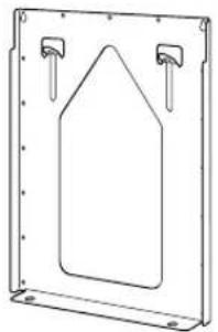
natural_image
Simple line drawing of a cabinet or rack frame with two hanging clips and a central triangular shape (no text or symbols)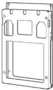
natural_image
Technical line drawing of a rectangular electronic device casing with mounting holes and internal compartments (no text or symbols)*Assembly completed for perpendicular installation.
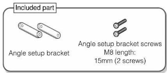
Angle setup bracket: 2
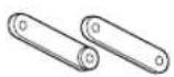
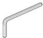
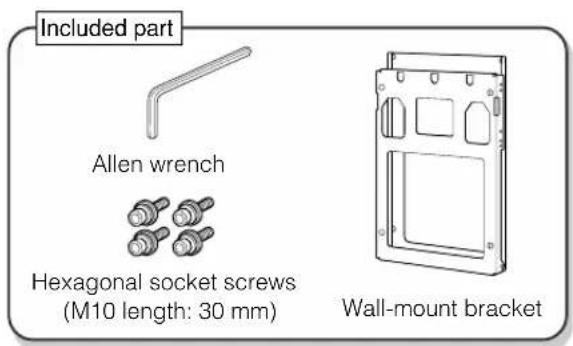
Allen wrench: 1
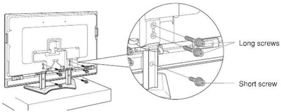
Screws
For fastening the wall-mount bracket

M6 length: 8mm (2 screws)
For the angle setup bracket

M8 length: 15mm (2 screws)
For installing the wall-mount bracket unit
M10 length: 30mm (4 screws) with hexagonal sockets
*The screw notation M6 means the diameter of the threaded part is 6 mm. *Please also store the screws that are not used.
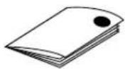
Operation manual (This manual)
Please use the following
• Wall installation screws (off-the-shelf) 17
Be sure to consult the dealership or a qualified contractor when installing the TV.
- Stand hole covers × 2 (Included with the LCD color TV)
- A plumb bob made by tying a coin with a hole in it to the end of a string.
• A pin, such as a thumbtack - Cushion, soft cloth, etc.
- Tool (Phillips head screwdriver)
Installation location
- LCD color TVs have a viewing angle (range in which the image can be viewed correctly). The best viewing position is from directly in front of the screen. Determine the TV installation location after taking into consideration the viewing posture, line of sight, and the visual and aural ranges.

- Sharp shall bear no responsibility for damages, etc., caused by the LCD color TV falling due to insufficient installation strength or improper installation.
Weight table (Unit: kg)
| Destination market | Appropriate Model | Model unit (no stand) | Fixture | Total Weight |
| Japan | LC-65GE1 | Approx. 65.5 | Approx. 10.5 | Approx. 76.0 |
1
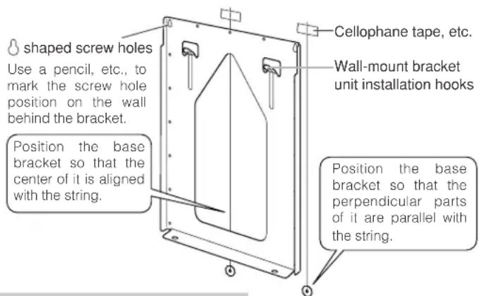
Determine the location where the base bracket will be installed.
(1) Use tape or other means to mark the measured positions on the wall where the display will be installed. The center of the "X" drawn from the four corners of the square marks the center of the panel.
(2) Take the coin with the string and align it perpendicular to the base bracket.
Use a pencil, etc., to mark the two screw hole locations.
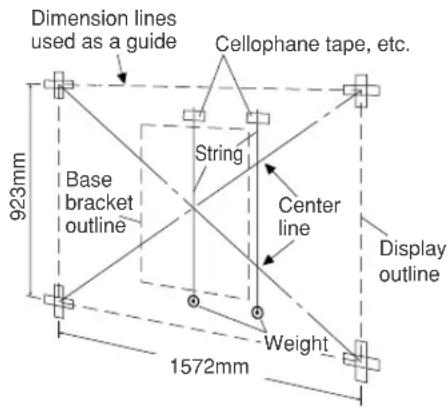
*When marking on the wall, use a material that will not leave a permanent mark on the wall and get the approval of the customer before beginning the work.
2
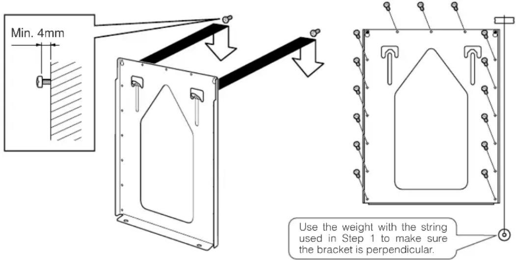
Tighten the screws
Temporarily remove the base bracket from the wall and loosely screw in off-the-shelf screws (8 mm dia. × 2 screws) in the screw hole positions marked on the wall. At this time, the screw heads should extend more than 4 mm above the wall so that the base bracket can be hung on the screw heads. Hang the base bracket on the installed screws, check to make sure the bracket is not sagging to the left or right, and then firmly tighten the screws. Use off-the-shelf screws to secure the remaining screw holes (15 screws). (The screw hole diameter is 9 mm.)
Installing the wall-mount bracket (For Model 65 inch Separate Type)

- Be sure to use at least two people to perform the wall-mount bracket installation work for the LCD color TV. - The installation work must be conducted while the LCD color TV is standing upright, so be careful that it does not fall over.
1
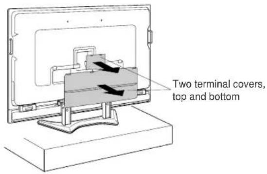
Place the LCD color TV on a strong stand about 20 to 30 cm high and remove the two back terminal covers.
Remove the terminal covers while the LCD color TV is standing upright. (2 covers top and bottom)
2
Remove the 3 fastening screws from both the left and right stands on the back of the LCD color TV.
Keep the removed screws (short × 2 screws, long × 4 screws).
3
(1) Remove the 2 screws from each of the stand edge covers (total of 4 screws from the left and right sides).
Use the removed screws (total of 4 screws) as shown in Step 2 on page 9.
(2) Remove the stand fastening screws (2 screws each on the left and right sides).
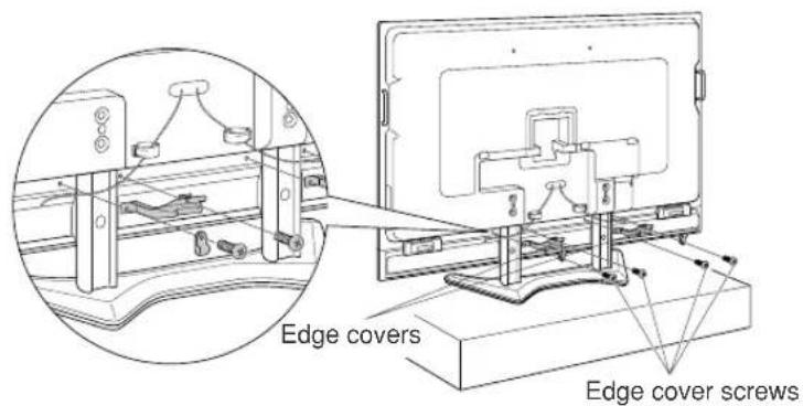
natural_image
Technical line drawing of a mechanical assembly with no visible text or symbolsRemoving the edge covers reveals the stand fastening screws in the center of the stands, so remove these screws.
Installing the wall-mount bracket (Continued)
4
Connect the system cables and power cord to the terminals on the back of the LCD color TV.
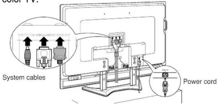
5
Use the cable holder at the center of the back of the LCD color TV and the cable holders holding the speaker cables to connect the system cables.
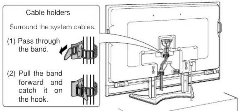
6
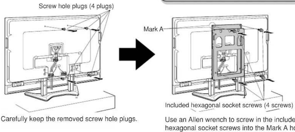
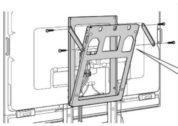
Remove the screw hole plugs (4 plugs) of the wall-mount bracket on the back of the TV and then screw in the 4 wall-mount bracket unit screws (hexagonal socket screws, M10 length: 30 mm) that are included with the wall-mount bracket unit.
Set the angle of the wall-mount bracket

- Please perform this work before mounting the LCD color TV on the wall.
- When setting the angle of the wall-mount bracket, be careful not to pinch your fingers, etc.
1
Remove the perpendicular positioning screws from the wall-mount bracket (2 screws each on the left and right sides).
These screws are used for the angle setup in Step 2.
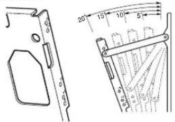
2
Assemble the included angle setup brackets as shown in the illustration and then use them to set the TV to the desired angle.
For the screws, use the included angle setup bracket screws (M8 length: 15 mm × 2 screws) and screws removed in Step 1.
First loosely tighten the 4 screws and then securely tighten them after the angle setup bracket is set to the desired position.
natural_image
Technical line drawing of a mechanical frame assembly with mounting brackets and structural supports (no text or symbols)The numbers 5, 10, 15, and 20 at the screw holes mean that the higher the number, the more the LCD color TV slants downward. The angle that can be set is limited depending on the TV model.
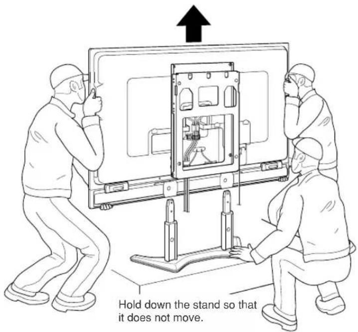
Remove the stands

- Be sure to use at least 3 people for the work from this point onward.
- Be very careful when holding the LCD color TV at a slant or when lifting it up.
1
Lift up the LCD color TV and remove the stand.
While the stand is being held down, lift up the LCD color TV to remove it from the stand.
*Remove the LCD color TV from the stand while tipping it backward slightly.
2
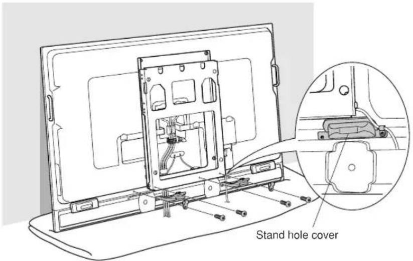
Temporarily place the LCD color TV on a cushion or soft material and install the stand hole covers that are included with the LCD color TV.
Hold the LCD color TV at a slant and align the stand hole covers (included with the LCD color TV) with the stand insertion locations.
Use the screws removed during Step 3 on page 6 to attach the stand hole covers and speaker cables.
E-8
Installing the LCD color TV on the wall

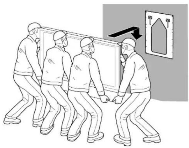
- Be sure to use at least 4 people when installing the LCD color TV to the base bracket.
- Be sure to perform Steps 1 and 2 below. Only performing Step 1 could result in the display falling and injuring someone.
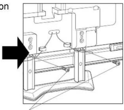
1
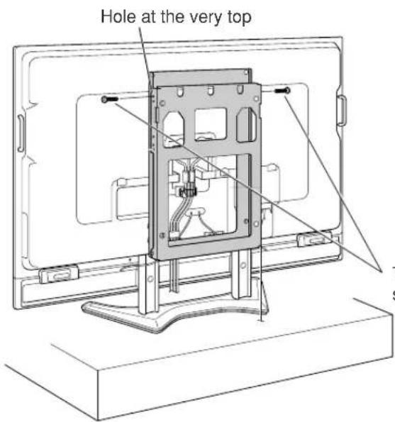
Install the wall-mount bracket attached to the LCD color TV to the base bracket.
Hang the square holes of the wall-mount bracket on the hooks (see page 5) of the base bracket unit.
Check to make sure the hooks are securely inserted into the notches at the top of the slanted side of the wall-mount bracket unit.
natural_image
Illustration of four workers pulling a wall-mounted device with an arrow pointing to a wall-mounted door (no text or symbols present)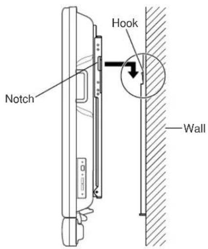
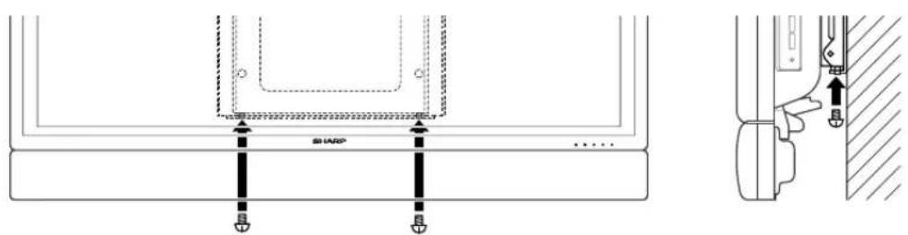
2
Fasten the screws in the wall-mount bracket unit and bottom of the base bracket (Be sure to do this).
Fasten using the included wall-mount bracket fastening screws (M6 length: 8 mm x2 screws).
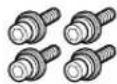
Included part

Wall-mount bracket fastening screws M6 length: 8mm (2 screws)
SHARP®
SHARP CORPORATION
Printed on 100% post-consumer recycled paper.