
SPH-DA120 - Car stereo PIONEER - Free user manual and instructions
Find the device manual for free SPH-DA120 PIONEER in PDF.
User questions about SPH-DA120 PIONEER
0 question about this device. Answer the ones you know or ask your own.
Ask a new question about this device
Download the instructions for your Car stereo in PDF format for free! Find your manual SPH-DA120 - PIONEER and take your electronic device back in hand. On this page are published all the documents necessary for the use of your device. SPH-DA120 by PIONEER.
USER MANUAL SPH-DA120 PIONEER
Your new product and this manual 3
Important safeguards 3
02 Connection
Precautions before connecting the system 4
Before installing this product 4
To prevent damage 5
- Notice for the blue/white lead 5
Parts supplied 6
Connecting the power cord (1) 8
Connecting the power cord (2) 10
Connecting the system 11
Connecting to separately sold power amp 12
Attaching identification labels to USB cables 13
Connecting an iPhone with Lightning connector 13
- Connecting via the USB port 13
- Connecting via the HDMI port 14
Connecting an iPhone with 30-pin connector 14
- Connecting via the AUX input 14
- Connecting via the RGB input 15
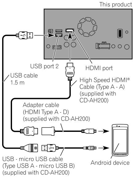
Connecting the Android ™ device 15
- Connecting an Android device with an HDMI port 15
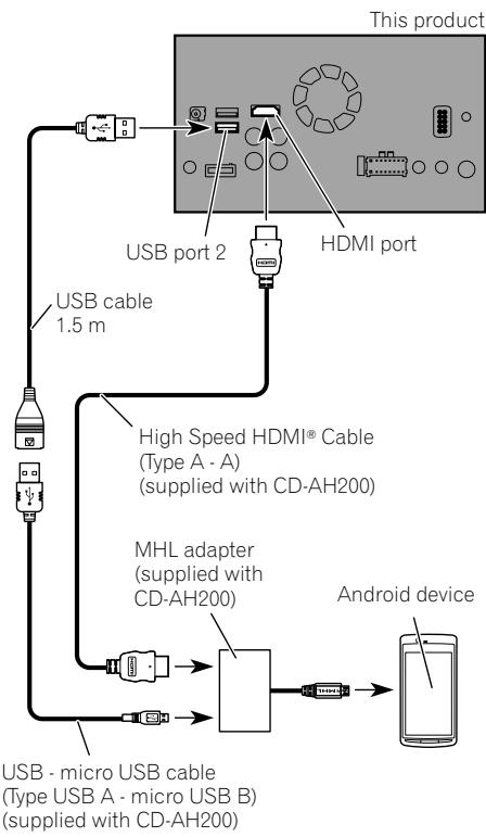
- Connecting an Android device with an MHL port 16
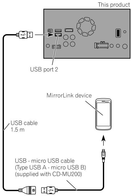
Connecting the MirrorLinkTM device 16
Securing the High Speed HDMI® Cable 17
Connecting a rear view camera 17
Connecting the external video component 18
Using AV input 18
-Using an AUX input 19
Connecting an HDMI device 20
Connecting the rear display 20
- When using a rear display connected to rear video output 20
03 Installation
Precautions before installation 21
To avoid electromagnetic interference 21
Before installing 21
Installing this product 22
Installation notes 22
- Parts supplied 22
- Before installing this product 23
- Installation with the holder 23
Installation using the screw holes on the side of this product 24
Installing the GPS aerial 26
- Installation notes 26
- Parts supplied 26
- When installing the aerial inside the vehicle (on the dashboard or rear shelf) 27
Installing the microphone 28
- Parts supplied 28
- Mounting on the sun visor 28
- Installation on the steering column 29
- Adjusting the microphone angle 29
04 After installation
After installing this product 30
Your new product and this manual
- Do not operate this product, any applications, or the rear view camera option (if purchased) if doing so will divert your attention in any way from the safe operation of your vehicle. Always observe safe driving rules and follow all existing traffic regulations. If you experience difficulty in operating this product or reading the display, park your vehicle in a safe location and apply the handbrake before making the necessary adjustments.
- This manual explains how to install this product in your vehicle. Operation of this product is explained in the separate manuals.
- Do not install this product where it may (i) obstruct the driver's vision, (ii) impair the performance of any of the vehicle's operating systems of safety features, including airbags, hazard lamp buttons, or (iii) impair the driver's ability to safely operate the vehicle. In some cases, it may not be possible to install this product because of the vehicle type or the shape of the vehicle interior.
Important safeguards
WARNING
Pioneer does not recommend that you install this product yourself. This product is designed for professional installation only. We recommend that only authorised Pioneer service personnel, who have special training and experience in mobile electronics, set up and install this product. NEVER SERVICE THIS PRODUCT YOURSELF. Installing or servicing this product and its connecting cables may expose you to the risk of electric shock or other hazards, and can cause damage to this product that is not covered by warranty.
- Read this manual fully and carefully before installing this product.
- Keep this manual handy for future reference.
- Pay close attention to all warnings in this manual and follow the instructions carefully.
- Traffic restrictions and advisories are always more important than guidance given by a third-party navigation/mapping iPhone application. Always obey current traffic restrictions, even if the application provides contrary advice.
- As with any accessory in your vehicle's interior, this product should not divert your attention from the safe operation of your vehicle as it may result in serious injury or death. If you experience difficulty in operating the system or reading the display, please make adjustments while safely parked.
- Please remember to wear your seat belt at all times while operating your vehicle. If you are in an accident, your injuries can be considerably more severe if your seat belt is not properly fastened.
- Certain country and government laws may prohibit or restrict the placement and use of this product in your vehicle. Please comply with all applicable laws and regulations regarding the use, installation and operation of this product.
Precautions before connecting the system

WARNING
Do not take any steps to tamper with or disable the handbrake interlock system which is in place for your protection. Tampering with or disabling the handbrake interlock system could result in serious injury or death.

CAUTION
- If you decide to perform the installation yourself, and have special training and experience in the mobile electronics installations, please carefully follow all of the steps in the installation manual.
- Secure all wiring with cable clamps or electrical tape. Do not allow any bare wiring to remain exposed.
- Do not directly connect the yellow lead of this product to the vehicle battery. If the lead is directly connected to the battery, engine vibration may eventually cause the insulation to fail at the point where the wire passes from the passenger compartment into the engine compartment. If the yellow lead's insulation tears as a result of contact with metal parts, short-circuiting can occur, resulting in considerable danger.
- It is extremely dangerous to allow cables to become wound around the steering column or gearstick. Be sure to install this product, its cables, and wiring away in such so that they will not obstruct or hinder driving.
- Make sure that the cables and wires will not interfere with or become caught in any of the vehicle's moving parts, especially the steering wheel, gearstick, handbrake, sliding seat tracks, doors, or any of the vehicle's controls.
- Do not route wires where they will be exposed to high temperatures. If the insulation heats up, wires may become
damaged, resulting in a short circuit or malfunction and permanent damage to the product.
- Do not cut the GPS aerial cable to shorten it or use an extension to make it longer. Altering the aerial cable could result in a short circuit or malfunction.
- Do not shorten any leads. If you do, the protection circuit (fuse holder, fuse resistor or filter, etc.) may fail to work properly.
- Never feed power to other electronic products by cutting the insulation of the power supply lead of this product and tapping into the lead. The current capacity of the lead will be exceeded, causing overheating.
Before installing this product
- Use this unit with a 12-volt battery and negative earthing only. Failure to do so may result in a fire or malfunction.
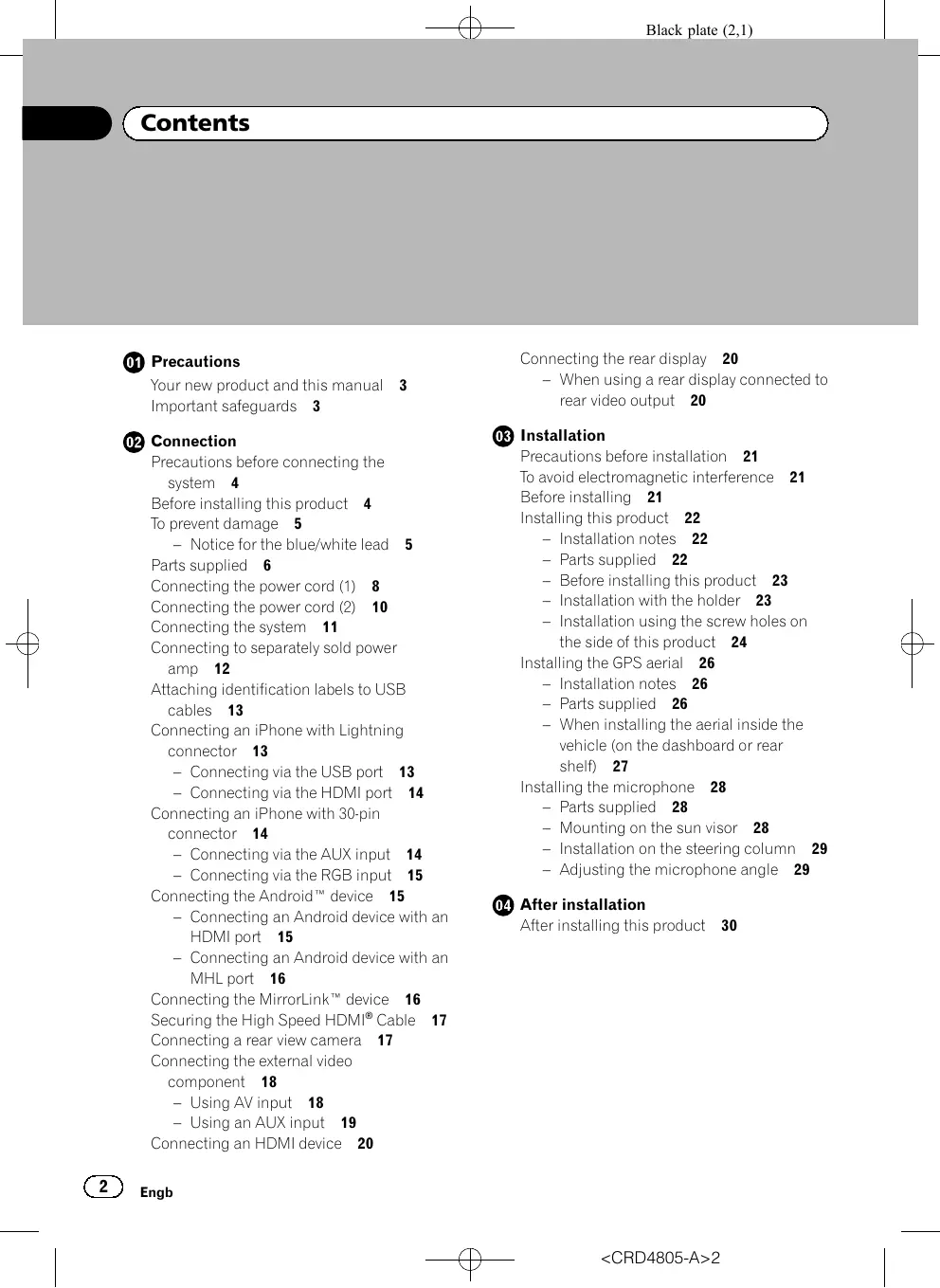
- To avoid shorts in the electrical system, be sure to disconnect the (-) battery cable before installation.

To prevent damage
WARNING
Use speakers over 50 W (output value) and between 4 to 8 (impedance value). Do not use 1 to 3 speakers for this unit.
- The black lead is earth. Please earth this lead separately from the earth of high-current products such as power amps. Do not earth more than one product together with the earth from another product. For example, you must separately earth any amp unit away from the earth of this product. Connecting earths together can cause a fire and/or damage the products if their earths became detached.
- When replacing the fuse, be sure to only use a fuse of the rating prescribed on this product.
- When disconnecting a connector, pull the connector itself. Do not pull the lead, as you may pull it out of the connector.
- This product cannot be installed in a vehicle without ACC (accessory) position on the ignition switch.

ACC position

No ACC position
- To avoid short-circuiting, cover the disconnected lead with insulating tape. It is especially important to insulate all unused speaker leads, which if left uncovered may cause a short circuit.
-
Attach the connectors of the same colour to the corresponding coloured port, i.e., blue connector to the blue port, black to black, etc.
Refer to the owner's manual for details on connecting the power amp and other units, then make connections accordingly. -
Since a unique BPTL circuit is employed, do not directly earth the side of the speaker lead or connect the side of another side of the speaker lead together. Be sure to connect the side of the speaker lead to the side of the speaker lead on this product.
Notice for the blue/white lead
- When the ignition switch is turned on (ACC ON), a control signal is output through the blue/white lead. Connect to an external power amp's system remote control terminal, the auto-aerial relay control terminal, or the aerial booster power control terminal (max. 300 mA 12 V DC). The control signal is output through the blue/white lead, even if the audio source is switched off.
- Be sure not to use this lead as the power supply lead for the external power amps. Such connection could cause excessive current drain and malfunction.
- Be sure not to use this lead as the power supply lead for the auto-aerial or aerial booster. Such connection could cause excessive current drain and malfunction.
Parts supplied
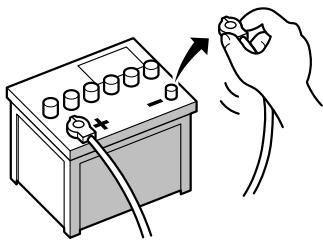
This product
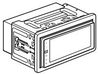
Power cord
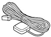
GPS aerial
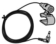
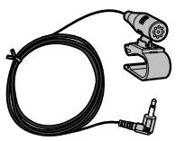
Microphone
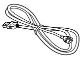
USB cable (2 pcs.)
USB cable identification labels
Lock tie

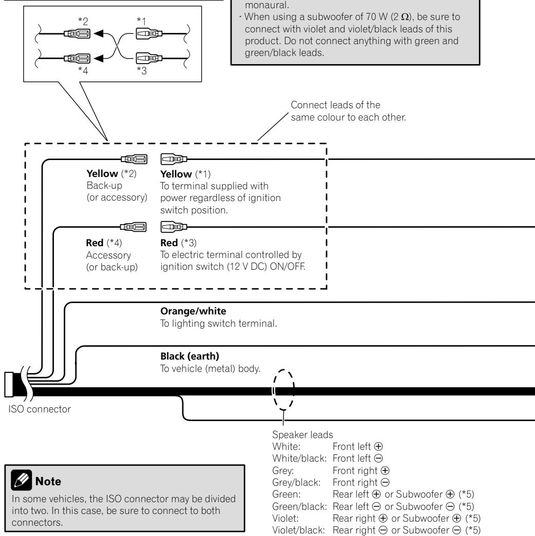
Connecting the power cord (1)

Note
Depending on the types of vehicles, the function of 2 and 4 may be different. In this case, be sure to connect 1 to 4 and 3 to 2 as shown in the figure.
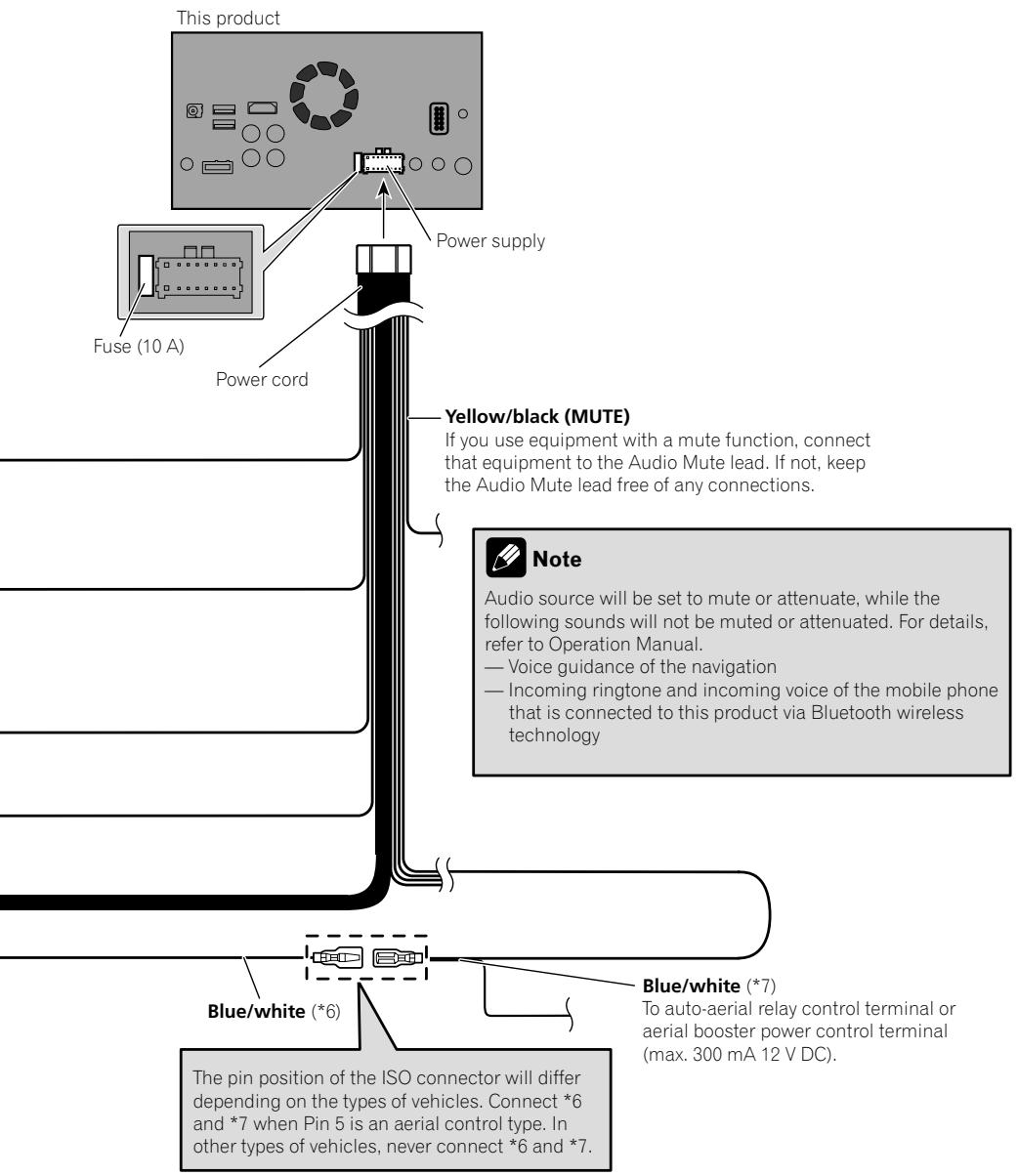

Connecting the power cord (2)


Connecting the system
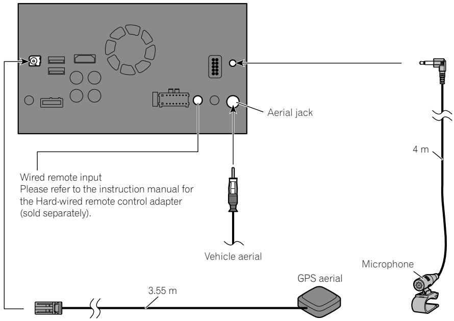
This product

WARNING
- To avoid the risk of accident and the potential violation of applicable laws, this product should never be used while the vehicle is being driven except for navigation purposes. And, also rear displays should not be in a location where it is a visible distraction to the driver.
- In some countries, the viewing of images on a display inside a vehicle even by persons other than the driver may be illegal. Where such regulations apply they must be obeyed and this product's video source should not be used.

Connecting to separately sold power amp
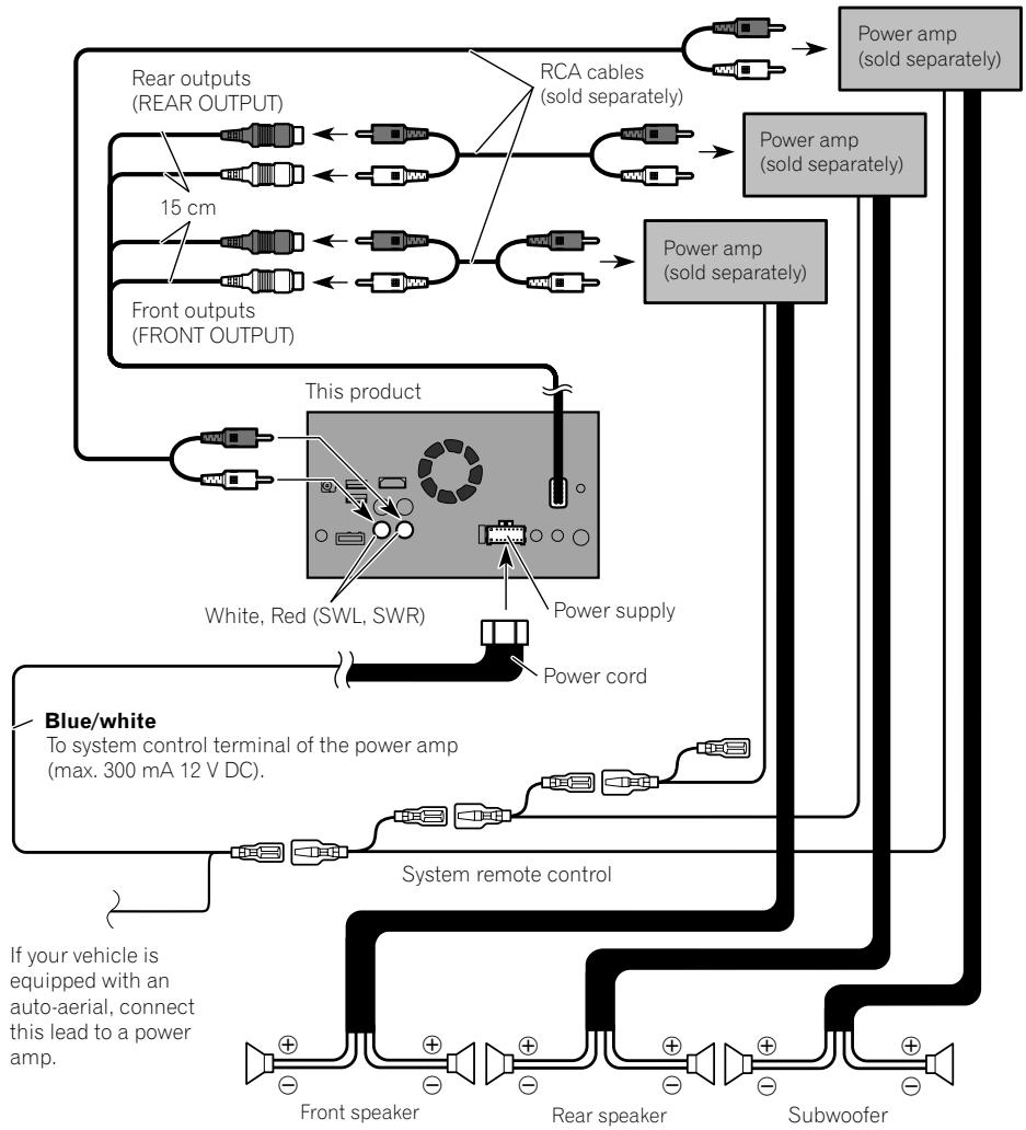

Notes
- You can change the RCA output of the subwoofer depending on your subwoofer system. (Refer to Operation Manual.)
- The subwoofer output of this product is monaural.

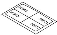
Attaching identification labels to USB cables
Attach identification labels to USB cables before installing this product in a vehicle.
1 Connect USB cables to the USB port 1 and 2 on the rear of this product.
2 Attach the identification labels corresponding to each port to the USB cables as illustrated below.

Attach the "PORT 1" label to the USB cable connected to the USB port 1.
Attach the "PORT 2" label to the USB cable connected to the USB port 2.
Connecting an iPhone with Lightning connector

Notes
- For details on how to connect an external device using a separately sold cable, refer to the manual for the cable.
- For details concerning the connection, operations and compatibility of iPhone, refer to Operation Manual.
Connecting via the USB port
The USB interface cable for iPod / iPhone (CD-IU52) (sold separately) is required for the connection.
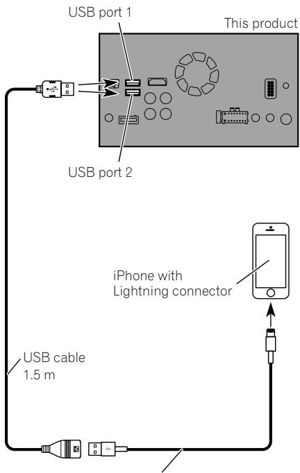
USB interface cable for iPod / iPhone (CD-IU52) (sold separately)

Note
Connect the USB cable to USB port 1 when using Apple CarPlay.
Connecting via the HDMI port
The following cables are required for the connection.
- HDMI interface cable for iPod / iPhone (CD-IH202) (sold separately)
- USB interface cable for iPod / iPhone (CD-IU52) (sold separately)
Lightning Digital AV Adapter (Apple Inc. products) (sold separately)
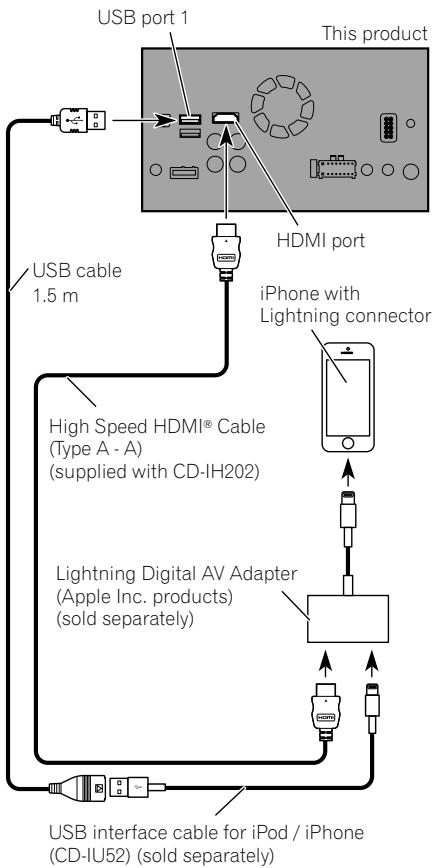

Note
- When you connect the High Speed HDMI® Cable, use the lock tie to fix it securely.
For details, refer to Securing the High Speed HDMI® Cable on page 17.
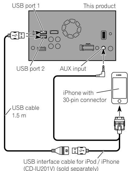
Connecting an iPhone with 30-pin connector

Notes
- For details on how to connect an external device using a separately sold cable, refer to the manual for the cable.
- For details concerning the connection, operations and compatibility of iPhone, refer to Operation Manual.
Connecting via the AUX input
The USB interface cable for iPod / iPhone (CD-IU201V) (sold separately) is required for the connection.
Connecting via the RGB input
The USB interface cable for iPod / iPhone (CD-IU201S) (sold separately) is required for the connection.
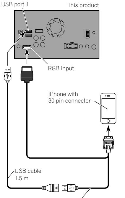
USB interface cable for iPod / iPhone (CD-IU201S) (sold separately)

Connecting the Android device
App Connectivity Kit (CD-AH200) (sold separately) is required for the connection.

Notes
- For details on how to connect an external device using a separately sold cable, refer to the manual for the cable.
- For details concerning the connection and operations of Android device, refer to Operation Manual.
- When you connect the High Speed HDMI® Cable, use the lock tie to fix it securely.
For details, refer to Securing the High Speed HDMI® Cable on page 17.
Connecting an Android device with an HDMI port
Connecting an Android device with an MHL port
Connecting the MirrorLink device
The USB interface cable for use with MirrorLink™ devices (CD-MU200) (sold separately) is required for the connection.


Note
For details on how to connect an external device using a separately sold cable, refer to the manual for the cable.
Securing the High Speed HDMI® Cable
Be sure to fix the High Speed HDMI® Cable with the lock tie, when you connect the external device with the High Speed HDMI® Cable.
1 Insert the High Speed HDMI® Cable into the HDMI port.
2 Wrap the lock tie around the hook above the HDMI port and the High Speed HDMI® Cable, and then tighten it to secure the High Speed HDMI® Cable.
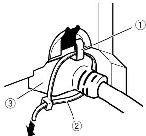
① Hook
② Lock tie
③ High Speed HDMI® Cable
- Do not tighten up the lock tie more than necessary.
Connecting a rear view camera
When this product is used with a rear view camera, it is possible to automatically switch from the video to rear view image when the gearstick is moved to REVERSE (R). Camera View mode also allows you to check what is behind you while driving.
WARNING
USE INPUT ONLY FOR REVERSE OR MIRROR IMAGE REAR VIEW CAMERA. OTHER USE MAY RESULT IN INJURY OR DAMAGE.
CAUTION
- The screen image may appear reversed.
- The rear view camera is used as an aid to keep an eye on trailers, or backing into a tight parking spot. Do not use this function for entertainment purposes.
- Objects in rear view may appear closer or more distant than in reality.
- Please note that the image area shown by the rear view camera may differ slightly when full-screen images are displayed when backing and when checking the rear of the vehicle while moving forward.
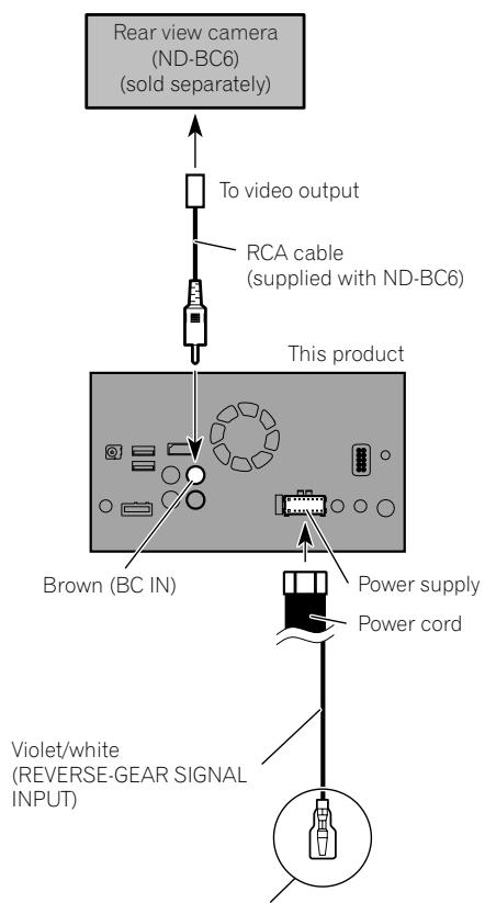
For more details about the wiring, refer to Connecting the power cord (2) on page 10.

Notes
- This mode is available when the rear view camera setting is set to "On". (For details, refer to Operation Manual.)
- Connect this product to the rear view camera only. Do not connect to any other equipment.
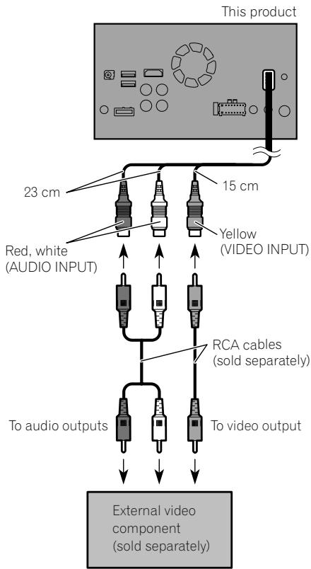
Connecting the external video component
Using AV input
You can connect an external video component to this product.

Note
This mode is available when the setting of AV input is set to "On". (For details, refer to Operation Manual.)
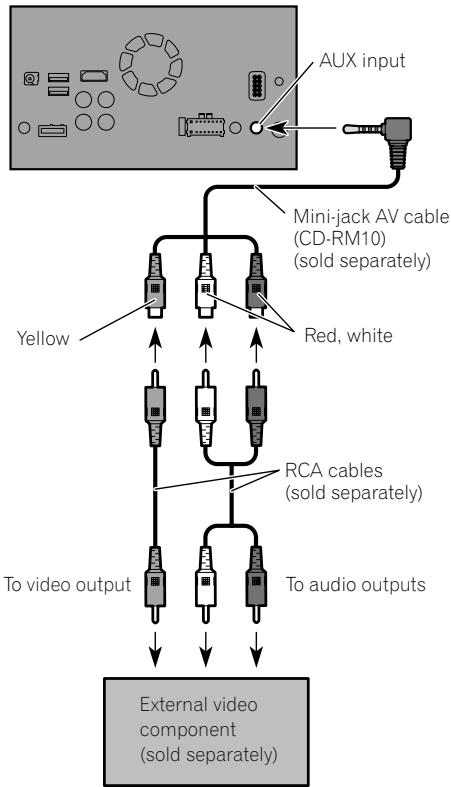
Using an AUX input
This product

Notes
- This mode is available when the setting of AUX input is set to "On". (For details, refer to Operation Manual.)
- When connecting an external video component using a mini-jack AV cable, use a separately sold AUX extension cable as necessary.

CAUTION
Be sure to use a mini-jack AV cable (CD-RM10) (sold separately) for wiring. If you use other cables, the wiring position might differ resulting in disturbed images and sounds.
| OK | ∅ |
| L V G R | L R G V |
L:Left audio (White)
R:Rightaudio(Red)
V : Video (Yellow)
G: Earth

Connecting an HDMI device
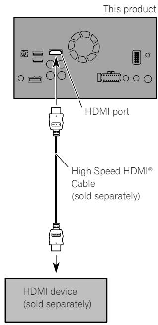

Notes
- For details concerning the operations of HDMI device, refer to Operation Manual.
- When you connect the High Speed HDMI® Cable, use the lock tie to fix it securely.
For details, refer to Securing the High Speed HDMI® Cable on page 17.
Connecting the rear display
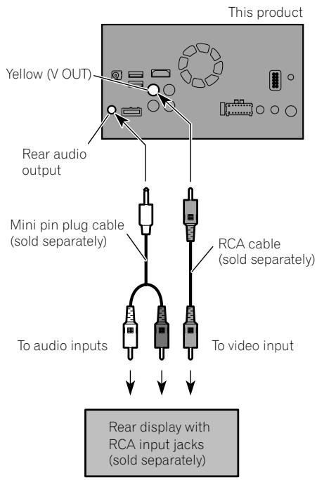
When using a rear display connected to rear video output

WARNING
NEVER install the rear display in a location that enables the driver to watch the video source while driving.
This product's rear video output is for connection of a display to enable passengers in the rear seats to watch the video source.
Precautions before installation
CAUTION
- Never install this product in places where, or in a manner that:
Could injure the driver or passengers if the vehicle stops suddenly.
May interfere with the driver's operation of the vehicle, such as on the floor in front of the driver's seat, or close to the steering wheel or gearstick.
- Make sure there is nothing behind the dashboard or panelling when drilling holes in them. Be careful not to damage fuel lines, brake lines, electronic components, communication wires or power cables.
- When using screws, do not allow them to come into contact with any electrical lead. Vibration may damage wires or insulation, leading to a short circuit or other damage to the vehicle.
- To ensure proper installation, be sure to use the supplied parts in the manner specified. If any parts are not supplied with this product, use compatible parts in the manner specified after you have the parts' compatibility checked by your dealer. If parts other than supplied or compatible ones are used, they may damage internal parts of this product or they may work loose and the product may become detached.
- It is extremely dangerous to allow cables to become wound around the steering column or gearstick. Be sure to install this product, its cables, and wiring away in such so that they will not obstruct or hinder driving.
Make sure that leads cannot get caught in a door or the sliding mechanism of a seat, resulting in a short circuit. -
Please confirm the proper function of your vehicle's other equipment after installation of this product.
-
Do not install this product where it may (i) obstruct the driver's vision, (ii) impair the performance of any of the vehicle's operating systems or safety features, including airbags, hazard lamp buttons or (iii) impair the driver's ability to safely operate the vehicle.
- Install this product between the driver's seat and front passenger seat so that it will not be hit by the driver or passenger if the vehicle stops quickly.
- Never install this product in front of or next to the place in the dashboard, door, or pillar from which one of your vehicle's airbags would deploy. Please refer to your vehicle's owner's manual for reference to the deployment area of the frontal airbags.
- Failure to follow all of these precautions may result in serious injury or death.
To avoid electromagnetic interference
In order to prevent interference, set the following items as far as possible from this product, other cables or leads:
FM, MW/LW aerial and its lead
GPS aerial and its lead
In addition, you should lay or route each aerial lead as far as possible from other aerial leads. Do not bind, lay or route them together, or cross them. Electromagnetic noise will increase the potential for errors in the vehicle's location display.
Before installing
- Consult with your nearest dealer if installation requires drilling holes or other modifications of the vehicle.
- Before making a final installation of this product, temporarily connect the wiring to confirm that the connections are correct and the system works properly.
Installing this product Installation notes
- Do not install this product in places subject to high temperatures or humidity, such as:
Places close to a heater, vent or air conditioner.
Places exposed to direct sunlight, such as on top of the dashboard.
Places that may be exposed to rain, such as close to the door or on the vehicle's floor.
- Install this product in an area strong enough to bear its weight. Choose a position where this product can be firmly installed, and install it securely. If this product is not securely installed, the current location of the vehicle cannot be displayed correctly.
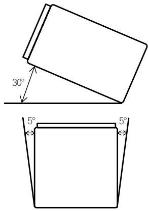
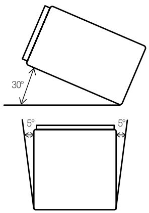
- Install this product horizontally on a surface within 0 to 30 degrees tolerance (within 5 degrees to the left or right). Improper installation of the unit with the surface tilted more than these tolerances increases the potential for errors in the vehicle's location display, and might otherwise cause reduced display performance.
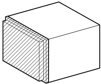
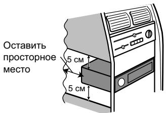
- When installing, to ensure proper heat dispersal when using this unit, make sure you leave ample space behind the rear panel and wrap any loose cables so they are not blocking the vents.
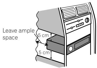
- The cords must not cover the area shown in the figure below. This is necessary to allow the amps to dissipate heat.
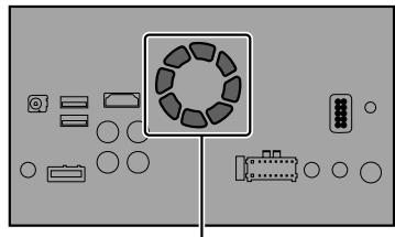
Do not cover this area.
Parts supplied
Parts marked (^*) are pre-installed.
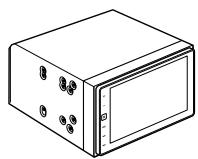
This product
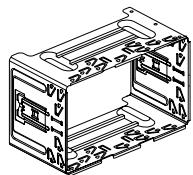
Holder*

Truss head screw
(5 mm × 8 mm)
(6 pcs.)

Flush surface screw
(5 mm × 9 mm)
(6 pcs.)
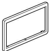
Trim ring*
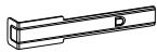
Extraction Key (2 pcs.)
Before installing this product
1 Remove the trim ring.
Extend top and bottom of the trim ring outwards to remove the trim ring.
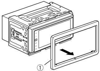
① Trim ring
2 Insert the supplied extraction keys into both sides of the unit until they click into place.
3 Pull the unit out of the holder.
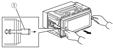
① Extraction key
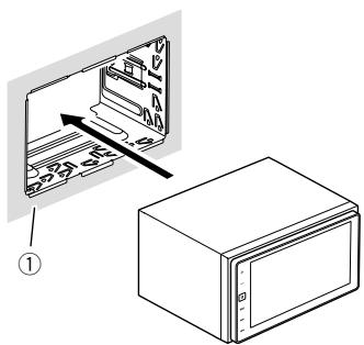
Installation with the holder
1 Install the holder into the dashboard.
2 Secure the mounting sleeve by using a screwdriver to bend the metal tabs (90^) into place.
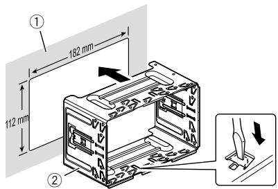
① Dashboard
② Holder
3 Install this product into the holder.

① Dashboard
- Do not squeeze this product into the holder. It may damage the front panel.
4 Attach the trim ring.
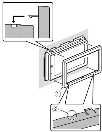
① Trim ring
② Groove
Attach the trim ring with the side with a groove facing downward.
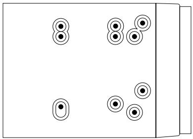
Installation using the screw holes on the side of this product
- Fastening this product to the factory radio-mounting bracket.
Position this product so that its screw holes are aligned with the screw holes of the bracket, and tighten the screws at three locations on each side.
Use either the truss head screws (5 mm × 8 mm) or flush surface screws (5 mm × 9 mm), depending on the shape of the bracket's screw holes.
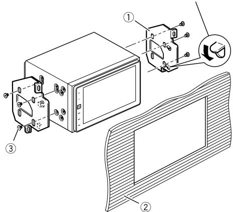
If the pawl interferes with installation, you may bend it down out of the way.
① Factory radio-mounting bracket
② Dashboard or console
③ Truss head screw or flush surface screw Be sure to use the screws supplied with this product.
Installing the GPS aerial

CAUTION
Do not cut the GPS aerial lead to shorten it or use an extension to make it longer. Altering the aerial cable could result in a short circuit or malfunction and permanent damage to this product.
Installation notes
- The aerial should be installed on a level surface where radio waves will be blocked as little as possible. Radio waves cannot be received by the aerial if reception from the satellite is blocked.
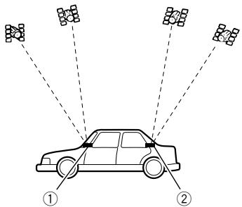
① Dashboard
② Rear shelf
- When installing the GPS aerial inside the vehicle, be sure to use the metal sheet provided with your system. If this is not used, the reception sensitivity will be poor.
- Do not cut the accessory metal sheet. This would reduce the sensitivity of the GPS aerial.
Take care not to pull the aerial lead when removing the GPS aerial. The lead may become detached. - Do not paint the GPS aerial, as this may affect its performance.
Parts supplied
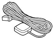
GPS aerial

Clamp (3 pcs.)


Metal sheet
Double-sided tape
When installing the aerial inside the vehicle (on the dashboard or rear shelf)

WARNING
Do not install the GPS aerial over any sensors or vents on the dashboard of the vehicle, as doing so may interfere with the proper functioning of such sensors or vents and may compromise the ability of the metal sheet under the GPS aerial to properly and securely affix to the dashboard.
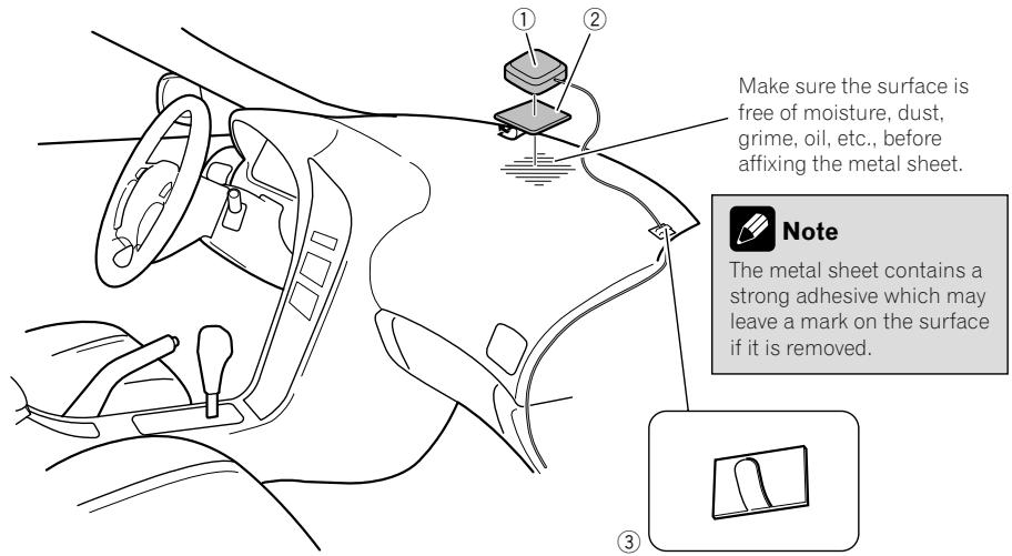
① GPS aerial
② Metal sheet
Peel off the protective sheet on the rear.
③ Clamps
Use clamps to secure the lead where necessary inside the vehicle.
Affix the metal sheet on the surface as level as possible where the GPS aerial faces the window. Affix the GPS aerial on the metal sheet using the double-sided tape.

Notes
- When attaching the metal sheet, do not cut it into small pieces.
- Some models use window glass that does not allow signals from GPS satellites to pass through. On such models, install the GPS aerial on the outside of the vehicle.

Installing the microphone
Install the microphone in a place where its direction and distance from the driver make it easiest to pick up the driver's voice.
- Be sure to turn off (ACC OFF) the product before connecting the microphone.
Parts supplied
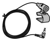
Microphone

Double-sided tape
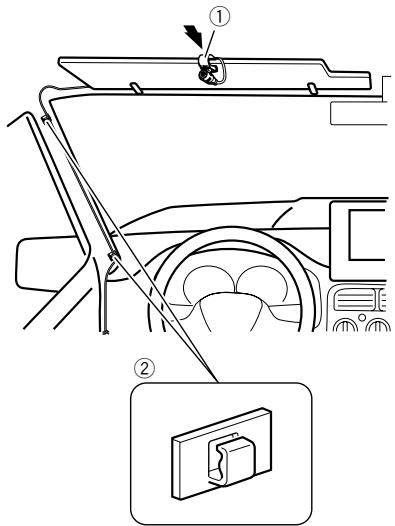
Mounting on the sun visor
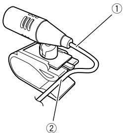
1 Fit the microphone lead into the groove.
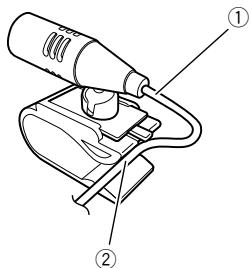
① Microphone lead
② Groove
2 Attach the microphone clip to the sun visor.
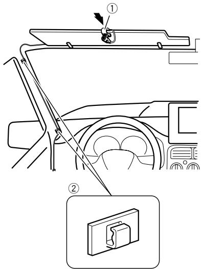
① Microphone clip
② Clamps
Use separately sold clamps to secure the lead where necessary inside the vehicle.
Install the microphone on the sun visor when it is in the up position. It cannot recognise the driver's voice if the sun visor is in the down position.
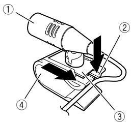
Installation on the steering column
1 Detach the microphone base from the microphone clip by sliding the microphone base while pressing the tab.
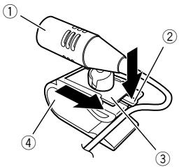
① Microphone
② Tab
③ Microphone base
④ Microphone clip
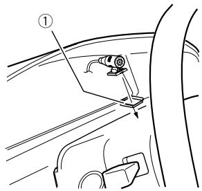
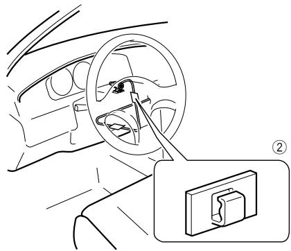
2 Mount the microphone on the steering column.
Install the microphone on the steering column, keeping it away from the steering wheel.
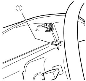
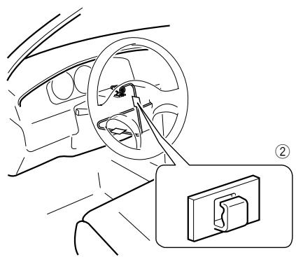
① Double-sided tape
② Clamps
Use separately sold clamps to secure the lead where necessary inside the vehicle.
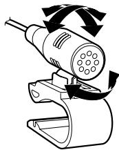
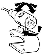
Adjusting the microphone angle
The microphone angle can be adjusted.

After installing this product
1 Reconnect the negative (-) terminal of the vehicle's battery.
First, double-check that all connections are correct and that this product is installed correctly. Reassemble all vehicle components that you previously removed. Then reconnect the negative (-) cable to the negative (-) terminal of the battery.
2 Start the engine.
3 Change the settings as desired.
For details concerning operations, refer to Operation Manual.
4 Drive down an unobstructed road until the GPS starts receiving the signal normally.

Note
After installing this product, be sure to check at a safe place that the vehicle is performing normally.
01 Précautions
| OK | ∅ |
| L V G R | L R G V |
Clamp firmly with needle-nosed pliers.

| OK | ∅ |
| L V G R | L R G V |
① Dashboard
② Houser
3 Installer dit product in de houder.
① Dashboard
Ipeed yctaHOBKO cnCTeMb1 184
YtO6bIu36eKaTbIOBpeXdEHH 185
-BHIMaHHe:CNHn/6eIbI npoBOd 186
B KOMNJIeK T BXOJNT 187
IopknloeHne cniloBoro shhpa (1) 188
IopKJIIOUeHHe CINOBORO UHypa (2) 190
IoiKJIIOUeHnE CNCTembl 191
POnkHoueHHe KOTdJIbHo npNo6peTeHHOMy yCINIHTeHMOuHOCtN 192
PnKpeHHe NdeHTnФkaUOnHHbIX HakJIeek K USB-ka6eIaM 193
IopKnIOUHe iPhone c pa3bEMOM Lightning 193
UCTaHObKa DaHHOrO u3dEInn 203
- Pekomehdaqun no yctahOBke 203
-BKOMnJIeKT BXoIuT 204 - IpepeyctahOBKOn CnCTeMbI 205
- YctaHOBKa C NOMOuBIO DePkaTeIa 205
- YCTaHOBKa C INCNoIb3OBAHHeM 60KOBbIX OTBepCTnIДЯ BHTOB DaHHOrO n3DeJIyra 206
YcTaHObKa GPS-aHTeHHbI 207
- Pekomehdaqun no yctahOBke 207
-BKOMnJIeKT BXOJNT 207 - YctaHOBka aHTeHHb BHyTpnaBTOMO6nIaHa npHOpHyIO paHeIbnn 3aHIO IOKy) 208
YcTaHOBKa MmKpOfoHa 209
-BKOMNJIeKTBXOJNT 209
- YcTaHOBKa Ha COJIHcE3aUHTHBiKo3bIpeK 209
- YctaHOBka Ha pyNeByIO KOIOHky 210
-PerynipoBka yrna MmKpOfoHa 210
04 NocJe yCTaHOBKn
Pocne yctahOBKn DaHHoro n3dennr 211
Baше Новoe Издени вданhoe руковозво
He nCnoJIb3yIte DaHHOe I3dJIeNE, JIObIeI npINIOXeHnI INI DOnOJIHInTeBHyU KAmepy 3aHrero BVda (B cnyae ee npNo6peTeHnI),ecNI 3TO MOKeT OTBNeUb BAsE BHNMaHne OT 63ONaChoro ynpabLeHnI ABTomoBnIe.M.BceJa c6bnIaJte npABnla 63ONaChoro BOxDeHnIu cyueCTByUOJIne npABnla dopoxHoro DBnIXeHn.EcN y Bac Bo3HKnI CToXHoCTn C ynpabLeHnEM DaHHbIM N3deJIeM INI C YTeHmE INHΦopMaIIN Ha DCnPJIee, npINpApKyuTE ABTomo6bIb B 63ONaChOM MeCTe IN NOCTaBbTE erO HA CTOrHOCHbI TopMO3 IpexKJe, Yem BBINOJIHHTb Heo6xoDImbIpe pErNJIpOBKn.
B DaHHom pyKOBOJCTBe OINcaH pIOcecc yCTaHOBKn DaHHoro IN3dEInn B aBTOMo- 6nIb. INCTpyKUnn PO 3KcNpyaTcuNn DaHHoro IN3dEInn PpeDCTaBNeHb I B OTdEINbHOM pyKOBOJCTBe.
He yctaHaBnBaIte daHnyo cnCTemy B TaKnx MecTax, rDe OHa MoXeT (i) 3atpydHЯTb 063Op BOInTeJIIO, (ii) yxUdUnTb pa6O-Ty IIO6bIX CNTEm ynpabJEnHn ABTOMO6NJEM nIN CNCTem 6e3OnacHOCTN, BKIIouyA NOdyuKKn 6e3OnacHOCTN, KHOPIKn ABapNIHOI CNHaJIIN3aCUN, INI (iii) npE- PNTBOBAtb BO3MOXHOCTN BOInTeJIa 6e3- ONACHO YnpaBnTb ABTOMO6NJEM. B HEKOTOPbIX CnyaXy UcTaHOBKa DaHHoI CNCTEmbl MOXeT 6bITb HeBO3MOXHa N3-3a Tnna ABTOMO6NJRA INI φOpMbI caIOna H aTOMO6NJIA.
Baxkhble Mepbl 6e30nacHOCTN
1 PPEyPExKdEHN
KomnaHn Pioneer He peKomeHnyet camoCTOaTeNbHO yCTaHaBnBaTb daHHeu3dEJIne.3To MOrYT BbINONHHTb TOnbKO cNeuaNtcbI NO yCTaHOBKe. YcTaHOBKa n Ha-CTPouKa CnCTeMbI DOJXHa npOn3BOAnTbCepBnCHbIM COtpyHnKamn Pioneer, mEIOUmm NoDrotOBky N oBt pa6Ot b C MObJIbHbIM 3JeKTPoHHbIM O6OpyDoBaHNem. HE OBCLNYKBAAITE CNCTEMY CAMOCTOaTEJIbHO. YcTaHOBKa nn ObScyXnBaHne u3-DeJInu N IOKJIIOHeHne IPOBOKn MOrYT 6bITb NODBerpyTb Bac pncyk nopaxhena3JeKTPnueckm TokOM n dpyrIm OnaCHOCTaM INn NOBpeNTb H3dEInne.B TaKOM cLyuea raPaANTNa CTaHOBITc HeedeCTBnTeHBHO.
- Пераустановковиделяьнмателноюпочтайдаанhoe ркobodctBO.
-ДерхиTe pyKOBODCTBOВdoCTynHOM MecTeДЯПONUyeHnHyxHoN INΦopMaL. - 06paTnte ocOboe BnHmAHne Ha BCE npEydnpExdEnna DaHHOro pyKOBoDCTBa, NTOUHO CNeDyIte BCem yKa3aHnM.
OrpaHnueHnnaBnKeHnnaI npEduynpeKJeHnBaCERda ImeoT 60nbUyIO BaxHoCTb, Yem yKa3aHnna IO dBNKeHnIO, KOtOpbie DaIoTc HABrAuaHOnHHbIM/KapTorpaHnCeCKm pnpJIoXeHnEM dJa iPhone, npedOCTabJIeHHbIM TpeTbe cToPOHO.H. Bcerda Co6IIoJaTe DeiCTByIOuNE B daHHbIM MoMeHT OrpaHnueHnna IO dBNKeHnIO, DaJe ECINn HactOraUee pnpJIoXeHne daet npOTNbONoJxHOe yKa3aHnE.
Kak n npytnye yctpoinCTBa B BaUeem ATOMo6nIe, daHHoe n3dEInne He DoJnxHO OTBLeKaTb BHIMaHHe BOINTeJI N CTaBNTb NOd yrpo3y 6eOtonacnoCTb DVBxKeHnN, NOCKoNBky 3TO MOKeT npNBecTN K cepBe3HbIM TpaBMam INI rNoBEn. EcNI BblNCbITbBAte CLOXHOCTn PpN IcONb3OBAHN CNCTeMbl INI YTEHN INHΦOpMaCmN Ha 3kpane, npnnapKyTeCb N BbINOJIHnTe Heo6xOdImbIe NaCTPOINKn.
Mepbl npedoctoPOXHOCTH
He 3a6bIbaIte IcIPOJIb3OBAIb peMHn 6e3-ONaCHOCTN BO BpeM yDINKHeHNABTOMo-6nJI. B cIyuae abapIn TpaBmbl MOryt OKa3aTbCra 6oJee cepBe3HbIM, eCNI peMeHb He 6bl npabINbHO npICTeRHyT.
B HeKoTOpbIX cTpaHax cyuEcTBuyOT 3aKOHOdaTeNbHbIe I npaBVteNcTBBeHHbIe 3a- npeTbI INI ORpaHnUeHnRA H NcNoJIb3OBAHnE 3TOrIO 3dEInra B BaIeM TpaHCnOPTHOM cpeIcTBe. O6ecneHbTe COOTBECTBnE DeIcTByIOUzIM 3aKOHaM IN HopMaM IO yCTaHOBKe I 3KcJIpyTaUzIN DaHHOrO 3dEInra.
Mepbl npedoctopoxHQCTn nepeid nodkloueHneM cnCTembl

PNEyPPEKDEHNE
He npednpinHmai Te kaknx-ln6o waor OTHOCHTeNbHO BMeaTeNbCTBa B pa60Tu nINOTKIIIOUeHn CnCTeMbI 6JOKnOBKn CTOHOuHoro TOpMO3a, KOtopa npedHa3NaYeHa dNBAwSe 3aunTb.I BMeaTeNbCTBO B pa60Tu nIN OTKJIIOUeHn CnCTeMbI 6JOKnOBKn CTOHOuHoro TOpMO3a MOKeT npNBecTu KcepBe3HbIM TpaBMam nIN rNoEIn.

BHIMAHNE
- EcIn Bbl peuHnIc amocToTeJIbHo yCTaHOBHTb CnCTeMy I NmEeTe OnbIT pa60TbICMObNlHBiM 3JIeKTPoHHbIM O6OpyOBAHNEM, B TOUHOCTN BblONHJrTe BCE INCHtpyKUnI, npINBeEHhIe B pyKOBoDCTBe NO yCTaHOBKe.
Kpenek npoBOKn DOnJXeH BbINONHtbcn c nOMOsIbKO Ka6eJIbHbIX XOMyTOB uNn 3OJauCIOHOH NJIeHTbl. He ocTabnTe orOJeHHbIe yuaCTKn npoBOKn.
3anpeaetc Hnpanmyo coeunHtB keIbI npOBOD cncTeMbI c akkymyIaTOPHO6bataeep. B npotNBHom cnyae Bv6paZuA DBnraTeMa MoKET Bb3BaTb NOBpeXdHn I3OJIaUN B MeCTe, rKe npOBOD npoxoIT OT naccxnpckoro caloHa K DBnraTeIO. B cnuyae pa3pbIbA I3OJIaUN KeJTOrO npOBoDA N KOHTaC mEtAnIIueCKIMN 3JeMeENTAMM MoKET npOn30iTN KOpOTKoe 3AmblKaHne, KOTOPoe pInBeDET K cepbe3HbIM NOBpeXdHnI M - Upe3BbIyauHOn opaCHO ocTaBnTb Ka6eHn HaMoTaHHbIMn Ha pyNeByIO KOONKU nII npbYar nepeKNIuOHeNnepeaU.ObraTeNbHO yCTaHaBnBaIte DaHHyO cNCTeMy, Ka6eHn InpoBoDky TaKIM o6pa3OM, QTo6bl OHn He npenrTcTBoBAJIn ynpabJIeHNIO aBTOMo6nIeM.
- Y6eDnTecb,чTo Ka6eJIn nIpoBoda He npenPCTByIOT n He 3aCenIIaIOTcra 3a
JIIObIe DvIXyUncEa DeTaN ABTOMO6nI, OOCoHNo pyJeBOe KOJECO, PbYar nepeKJIouChEnI nepeDaU, CToAHOuHbI TopMO3, HAnpaBIAJIOUcne BbIDBIXHOrO cINDeHbI, DBepi NII INIObIe qactN ynpabJIeHNr ABTOMO6NJEm.
- He npoklaabIbAte npoBOdky B 30hax BO3deiCTBnB BiCOKO TeMnepaTypbl.
PnHarpeBaHmN 3OJraCn NpOBoDa MOryt NOBpeDntbCyr, YTO npNBeTeK KOpOTKOMy 3aMbIkaHIO NIN dpyTm Henc- npaBHOCTa NOBpeXdEHIO npOdyKaT.
- He ykopaunBaIte npOBd Inna InoKnIOueHnra GPS-aHTeHHbI n He nCNoJIb3yIte yd-linHInTeH. YkopaUNBaHne nIu yDInHHeHne aHTeHHoro Ka6eJIa MoKet npBecTn K KOpOTKOMy 3aMbIkaHnIO nIi HeNCpPaBHOCTaM.
- He ykopaunBaIte dpyrHe npoBoa. B npoTnBHom clyuae 3TO BbI3OBet HenOnaAdKn B pa6ote 3auHTHOe (depXaTeJI pIaB-Koro npedeoxpaHITeJI, pe3ncToPA-ppeOxpaHITeJI, fNlbTpAr n.T.D.).
3anpeaetcnoabaTb nTaHne K 3eK- TPOHHbIMn3deJnM 3a CteYdaJeHnI N3OJIuIN CNIOBOr npOBoDAaHOrO n3- DeJN I NOkKnUChEnK Hemy.B 3ToM clyueae 6ydtnpBbIeHa npedeJbHO doNyctImaHarpy3ka nTO kTy dIra 3TOro npOBoA, yTO npBBeTeK ero nepe- rpeBy.
Ipeed yCTaHOBKOcNCTeMbI
IcnoJIb3yIte DaHHyo CnCTeMy ToJIbKO C 12-BoIbTHbIM aKkymyIaTOpOM n3a3EmNeHem OTPuCaTeMbHorO noJIouca. HeBbIIOJIHeHne 3TOrO ycNoBm MOKeT pInBecTn K BO3rOpaHnIO uIN HeNcPpabHOCTN.
-Bo n36eKaHne KopoTko 3aMbikaHnB 3NeKtpnuecko CnCTeMe O6ra3aTeJbHO OTcoEduHnTe Ka6eb(-) aKKymyIaTOpHoi 6batapeu nepeu yctaHOBkOi.


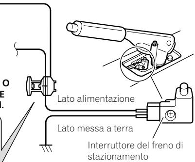
CBeTIO-3eJIeHbI (PARKING BRAKE)
IcnoIb3yeTcIyIOnpeJeHnIe
coTOrTHN BKJI/BbIKJpyHuHO TOpMO3a.
OT npBOoD Heo6XoIMNo IOcOeINHtB
K CTOPHe NpOauN 3Heprn BbIKIOuTeTn
pyHuHO TOpMO3a.
Pn HnepaBnHbOM CoeDHeHHNnn Iero TcYCTBnH NKeToOpBe yHKnUn daHOrO nIaDENn 6ydt Heoctynbl.

PpimmeaHne
Pionoxhenx CxmbIOpedeHnHnCKOcTNI BbIKHOATeRyPHOTORMO3aBapbHyETBa3ABNCMOCTOn OT MOeHN ABTOMBoNIOPO6HyUHΦOPMAUHO M0XHO y3HaTbYABOTNO3BOHANO DInepaKOMTAHnPione HneJIcNAJINCTOB NOyCTAHOB
Mepbl npedoctoPOXHOCTNIpeed yctaHOBkoI

BHIMAHNE
3anpeuho yctahabnBaTb cnCTemy TaM nn Takm o6pa30m, rke:
OHa MoKeT HaHeCTn TpaBMy BODInTeIHO nn naccaxKnpam B Cnyae pe3KoJ oc-TaHOBKn aBTOMO6NJ.
Moxet npenTCTBOBaTb ynpaBHeHIO BOINTEJIe m ABTOMO6NJIA, HAnpIMep, Ha NONY HAnpOTNB BOINTeJbCKORo cnDeHbA, B6JIu3n pyJeBoro KOleca nIpbYuara nepeKJIuOHeHnapeDaq.
- Ppi npocBepnBaanm OTBepCTn y6eNTecb, YTO nOJ nAHeJIbIO npIbOpOB IN dpyrnnn nnHeJIaMn OTCyTCTByOT DeTaN. HeNOBpeHte TOnIIINBhIE JInHN, TopMO3HbIe JInHN, 3JIeKTPOHHBe KOMNoHEHTbl, npBODa CBA3N INCINOBbIe Ka6eNl.
-ПинспользованибоNTOB He donny-ckaite nx KOHTaTc c 3neKtpuYeCKmnpoBoDAmN.ВибрацmaМожет NOBpeNTbnpoBOda nINn 3OJIaCnIO, npVBecTN K KOpOTKOMy 3ambIkaHnIO nIN dpyrIM NOBpeJxDeHnAM aBTOMO6nJIa.
Дяюобсесуеня npabunbhoи yctanobK nCledyet nCNoIb3ObaTb DeTaN, BXODa- une B KOMNJIeKT N COOTBeTCTBEHNO yka3aHHbIM npoceduypam. Ecn KaKe- IIN6o DeTaN He NoCTabJrHOTc C n3de- JInem, nCNoIb3yIte COBMeCTMlbE DeTaI IN COOTBeTCTBEHNO yka3aHHbIM npoceduypam nocLe npOBepKn DeTaN eINJePom Ha COBMeCTMocTb. Ecn nCnONb3yIOTc H OpuHNaHbIbe INn H COBMeCTMlbE DeTaN, 3TO MOxET npiVe- CTN K NOBpeJXeHnM BHyTpEHnX DeTaN DaHHoro n3DeJnN INn Ocna6tBu INx KpenNeHne, B pe3yIbTaTe Yero n3dEnne MOxET OTDeJIITbcrOT NaHeNn KpenNeHn. - Upe3BbIyauHOb onacho OocTabJIbKabeHnHaMoTaHHbIMn Ha pyuJeByU KOIOHky nII npbIar nepeKJIuOeHn pepeaU.ObraTeIbHO yCTaHaBnBaJte DaHHyo CnCTeMy, Ka6eHn InpOBdKy TAKM Obpa3OM,
TO6bI OHN He npenTCTBOBaN ynpabJIeHnO aBTOMo6NJem.
- 86eHNTecb, YTO npoBOda He HaxOJrTcB KOHTaKTe C DBePAMN NIN CdBnraIOUIMCM RexaHN3MOM CNDeHNI, YTO MOKeT pInBeCTN K KOPOTKOMY 3aMbIkaHNU.
- 6eintecb B haJlekaeem fYHKUHOHPOBaHHn dpyrOo obOpyOBaHnA BTOMo6nJI NocJe yCTaHOBKn DaHHoro n3deJIIn.
He yctaHabnBaIte daHoe n3deJIne B TaKnx MeCTax, rDe OHO MoKxET (i) 3aTpudHЯTb o63Op BOuNTeHIO, (ii) yUxDunTB pa-60Tu IIO6bIX CnCTem ynpaBnEnHaBTOMo6nIeM uIN CnCTem 6e3OnaNCHocTN, BKJIouyA NOdyuKN 6e3OnaNCHocTN, KHOKN abapnHOc nRHaIN3aUnn, uIN (iii) npEJaTCTBOBaTb BO3MOxHOCTHuBOuNTeIe 6e3OnaCHO ynpaBnTb ABTOMo6nIeM. - UctaHOBnte DaHHe O3DeJIne Mekdy BOIITbckIM N naccKnprCKIM CnDEHbeM TaK, YTO6bl pni pe3KOM TOpMOxEHn erO He CMOrJIN NOBpeDHTb BOIITeJIb IJI IN naccaxIp.
HnKorda He yctaHaBnBaIte DaHHoe n3- DeJIne HAnpOTNB IIN pRAOM C MeCTOM Ha npN6bOpHOI paHEJI, DBepu IIN cTOnKe, OTkyDa 6ydtocUyecTBJrTBcpa3BepbTaIBaHHe NOdywek 6e3OnaCHOCTn ABTOMO6NJIA. O6paNTeCb K pyKOBOdCTBy NOJIb3OBATeJIABTOMO6NJI dI NONYeHNI INΦOpMaUN OTHOCTBJHO MeCT pa3BepTBiBaHnIpepeHNX NOdywek 6e3ONaCHOCTN.
HeBbINOpHHeHne BcEx 3TuX MeP npEdoCToPOxHOCTn MOKeT pNBEcTn K cepbe3HbIM TpaBMam IIN rI6eJI.
3aunTa OT 3JIeKTpOMaHnTHbIX NOMex
ДязштбгOTэнктрмогнтьхnomex Cледуюшпve yctpoiCTBa Heo6xOДМо pa3me-цаТьHa MaKcMmaHbHompacCTOrHnOT daH-HoroИЗдени,дугnxKa6eNeипи npobODOB:
FM, MW/LW-aHTeHnHa n npoBOD
GPS-aHTeHHa n npoBOd
Kpome toro, cneyuET OcyuEcTBnTb npokla- dIbIaHne nIpa3BOkky npOBoDA kKaJDo aHTeHHbl KAK MOXHO daIbIe OT npOBOOB dpyrnx aHTeHH. He cBra3bIaIte, He npokna- dIbIaIte n He pa3BOdInTe INx BmecTe, IIN60 6bn3KO npyr Kdpyr. 3JeekTpomarHnTHble nomexn NOBbIaHOT BepoTHocTb BO3HnKHOBeHn HOn60 npn OTO6paKeHn MeCTONOLOKeHn ABTomO6NJIA.
Ipepe yctaHOBkoI
- 06paTntecb K CBOeMy DnIepy DnI nOlyeHn INDopMaUm O TOM, HUxHo JIn DnIa OCyUeCTBHeHn YcTaHOBKn CBePnITb OTBepCTNn IIN BHOcNTb DpyIne N3MeHeHn B KOHCTpyKlIuO ABTomObIJI.
- Perede OKOHuaHem yCTaHOBKn CnCTEmbI BbIOJIHNTE BpemeHHoe COeINHeHne npoBOIOB, YTO6bI y6eINTBcR BnpaBnBHOCTN BbIOJIHeHHbIX IPOKJIUChEHH N HaJNeJa-uei pa6Ote CnCTEmbl.
yCTaHOBka DaHHORo n3dJIIny PeKOMeHdauzn IIO yCTaHOBKe
3anpeaeta yctahabnBaTb daHHoe n3- DeJIne B MeCTax,IOBBepraIoXxCB03- DeIcTBnIO BbICOKNX TeMpeaTyp IIN BJIaJxHOCTN, HAnpIMep B MeCTax:
-6JINKaiuNX KOTONITeNBHbIM,BEHTIJIaUHOHHbIM OTBepCTnM NIN DnΦpy3Opam KOHNIOHOhepa.
—HaKOTOpbIe InonaJaIOITnpMbIe CONHeuHbIe JUyn,HaNPmEp,Ha NOBepxHOCTn PnB6OpHoi NaHeII.
—Ha KOTOpbIe MoXeT IOnaJaTb DoXJb, HApPImep, Bo3Je DBeRn NIn Ha IOny ABTOMO6uNJa.
- UctahabnabaTe DaHnOe n3dEne B MeCTax, cnooc6hBix Bbldepkatb ero BEc. Bbl6epnte Takoe MeCTo, Ige n3dEne MoKet 6blbHaJekHO yCTaHOBNeHo n3akpeIHeNo. B cnyuae HeNaJexHoro 3akpeIHeNHaHHO n3dEne He CMOxET ONpeJeNTb MaKcImaJIbHO TOUHO MEcTOnOJIOXeHne ABTOMO6nIy.
- UctahabnBaIte daHnoe n3dEne rOpn30HTaJIbHO Ha NOBepxHocTn, IMeOuSei OT-KIOHeHne B IpeDeJax O T 0 do 30 rpaDycob (B ppeJeax 5 rpaDycOB BLeBO uIn BnpABO). HeHaIeJaSaaY cYCTaHObKa 6Ioka Ha NOBepxHocTn C hAKIoHOM, ppeBbIshaUcIM yka3aHHbIe OTKIOHeHn, POBbIaET BepoTHOCtB BO3HKnHOBeHn OUn6okPnOTo6paeHn MeCtOnOLOKeHn ABTOMo6nI, IN MoKet YxUdIaTB XapakTepcntkN OTo6paKeHn INhblm cnoc6bom.
- UTo6bI o6eNeuTb HaIeKaUee paCCenBaHHe TEnla BO BpEma NcNoJIb3OBaHNJaDAnHO rO yCTpoiCTBa, pRn BByIOJHEnHr YCtAHOBKn CneJeYET y6eNtBcR, YTO nO3aIN3aHEn IaHEn OCTaBnEHO DoCTaTOHOCBO6oHOrO IpocTpaHCTBa, IN CBepHyTB BCE CBO6oHbIe Ka6eNl TaKIM Obpa3OM, UTo6bI OHn He 6nOKIpOBaJIin BeHTnJIaLIOOHbIe OTBepCTnIa.
IcnoIb3yIte 3aXIMbl IJI KpePJIeHnI pOBoDA BHyTpI aBTOMo6nIy.
3aKpeNITe MeTaNINueCKyIO pIaCTHNY B MaKcMmaJIbHO TOpN3OHTaJIbHOM NIOJoxEHN BMeCTe, Ie GPS-aHTeHna ObaIeHa K OKHy. 3aKpeNITe GPS-aHTeHny Ha MeTaNInueCKoI pIaCTHHe C NOMOuBIO DByCTOPOHHe R CKOTa.

PpimmeuHn
- Пи Креллени Металлческий плacrны He pa3pe3aIte ee Ha MeKneЧаст.
Ha HeKOTopbIX MoDeJIaX ABTOMoBnIeN B OKHax yCTaHaBnIbAHTcraTKeIa, KO-TopbIe He npOnyckaIOT CInrHaIbI c GPSCnyTHnka. Ha TaKHX MoDEJx GPS-aHTeHHy Heo6xOJIMO yCTaHaBnIBaTb ChapyJN abTOMoBnIJ.

YctaHOBka MnkpofoHa
- UctahOBHTe MmKpOoH B TakOM MecTe HnHa TAKOM pacCToHnC, C KOTOPOrI JeRKO 6yDet BOCPnPnHmAtbCraTJLOc BOITeJIa.
- Y6eIITecb B TOM, yTO I3dJIeNHe BbIKJIOUeHcHo (ACC OFF) npei npdkJIIOUeHnEm MKNKPOΦOHa.
B KOMnJIeKr BXoJNT
Minkpofoh

BvctOpOnnnaJIeHTa
YCTaHOBka Ha COJHcE3aUHTbI K03blpeK
1 PpOLOXnTe npoBmKpOfoHa B na3.
① Пювов микрочана
② Πa3
2 3akpennte 3axnM Ha coJIHue3aunT- HbIKo3bIpeK.
① 3aXmMnKpOoHa
② 3aXIMbl
IcnoIb3yIte OTdJIbHO npOdaUoIeCe 3aJXIMbl, YTO6bl 3aKpeNITb PBOOB BHyTpnaBtOMo6nJIr TaM, ITe 3TO Heo6xOdmo.
YcTaHaBnBaIte MmKpOfoH Na Ko3bIpeK, KOrDa OH HaxoDITC8 B NOHrTOM NIOXKeHIN. EcIn CoIHue3aUHTbIy Ko3bIpeK HaxoDITc8 B ONyueHHOM NIOXKeHIM, rOLOC BOdITeJI MoKeT He paCnO3HaBaTbcra.
YctaHOBKa Ha pyJeByIO KOJOhKy
1 OToeHNHTe NOCTabky MmKpOoHa OT 3aXIMMa MmKpOoHa, NpeEbnraa POCTabKy MmKpOoHa npn HaxaTOM JneectKe.
① MinkpohoN
② JIenecToK
③ Побста вка мнкрфona
④ 3aKIMMnKpOoHa
2 3aKpeNITe MmKpOΦoH Ha pyNeBOJ KOJIOHKe.
YcTaHOBnTe MmKpOoHnHa pyNeBOy KOJIOHKe Ha DoCTaTOUHOM paCtOHRn OT pyNEBOrO KOJIeCa.
① DBycToPOHHraJeHTa
② 3aXnMbI
IcnoIb3yIte OTdJIbHO npOdaUoIeCe 3aJKIMbI, YTO6bl 3aKpeNITb IPOBOB BHyTpnaBtOMo6nJI TaM, TNe 3TO Heo6xOdmo.
Perynipobka yrga MnkpofoHa
YrOJI MmKpOfoHa MoXHO peRyInpoBaTb.

Iocne yctaHOBKn daHHoro n3dJIy
1 NOBTOPHO NOkHOnHe KJIeMMy (-) aKymyIaTopa ABTomo6nIa.
Дянача Двждп npовьтпраиь-HOCТь BыПОннEHЯ BCEX NOДКЛIOЧЕНИnpaВиьHOCТь yCTAHOBKN CNTeMbI.CMOHTpynte BCE paHee CHTbIe KOMПОЕНы ABTO-MobnJIЯ.3aTeM COeINHITe OTPNUaTeNbHbI(-) Ka6eJIb c OTPNUaTeNbHbIM (-) NOIHOCOMakKymyJrToPA.
2 3anycntteDbrarateJIb.
3 I3mehnTe hacTpoKn no CBOeMy ycmO-tpenIO.
日 PioP6Ho Oepaunn HacTpoKn OnPcHbI B PykoBocTBe no 3Knpyatau.
4 BeNTe aBTOMO6nIb no CBO6oHNo dopore do Tex nop, noka GPS-aHTenHa He haunet nonyata b cTaNbHb ciHaJ.

Приимechаиме
Iocne yctaHOBKn DaHOrO n3dJIeN B 6e3oNaHOM MecTe y6eDntEcB, YTO aBTOMoBnIb IcnpaBHo pa6oTaet.
PIONEER CORPORATION
1-1, Shin-ogura, Saiwai-ku, Kawasaki-shi, Kanagawa 212-0031, JAPAN
Kopnpaця Паонир
1-1, CnH-Orypa, CaBbA-ky, r. KaBacKn, npedekTypa KaHaraba, 212-0031, JnoHnIa
Mnptep OOO "NHOEP PYC"
125040, Pocnra, r. MockBa, yI. PpaBbl, d.26
Ten.: +7(495) 956-89-01
© PIONEER CORPORATION, 2014.
Bce npaba 3aunuenebl.