
HDMC9800LB - Range hood HOOVER - Free user manual and instructions
Find the device manual for free HDMC9800LB HOOVER in PDF.
| Brand | Hoover |
| Model | HDMC9800LB |
| Product type | Extractor / recirculation hood |
| Power supply | 220-240 V, 50 Hz, insulation class II (without earth) or I depending on model |
| Motor power | Not specified, check rating plate |
| Lighting | LED or halogen depending on version (replacement by technician for LED) |
| Controls | Touch or mechanical depending on version |
| Motor speeds | Up to 4 speeds with intensive function (6 min) |
| Timer | Yes, automatic shut-off after 15 min |
| Minimum safety distance | 45 cm between hood and hob (gas, electric or induction) |
| Grease filter | Washable in dishwasher or by hand, every 2 months |
| Activated carbon filter | Non-regenerable (replace every 4 months) or regenerable washable (every 2 months, replace every 3 years) |
| Filter saturation indicator | Flashing display (F for grease filter, C/F for carbon filter) |
| Filter memory reset | Press button B for 3 seconds after cleaning |
| Installation | Wall-mounted, external extraction or recirculation version, decorative chimney optional |
| Exhaust duct diameter | Same diameter as air outlet (reduction not recommended) |
| Maintenance | Clean exterior and interior with denatured alcohol or neutral detergent |
| Energy consumption | Not specified |
Frequently Asked Questions - HDMC9800LB HOOVER
User questions about HDMC9800LB HOOVER
0 question about this device. Answer the ones you know or ask your own.
Ask a new question about this device
Download the instructions for your Range hood in PDF format for free! Find your manual HDMC9800LB - HOOVER and take your electronic device back in hand. On this page are published all the documents necessary for the use of your device. HDMC9800LB by HOOVER.
USER MANUAL HDMC9800LB HOOVER
Fig.5
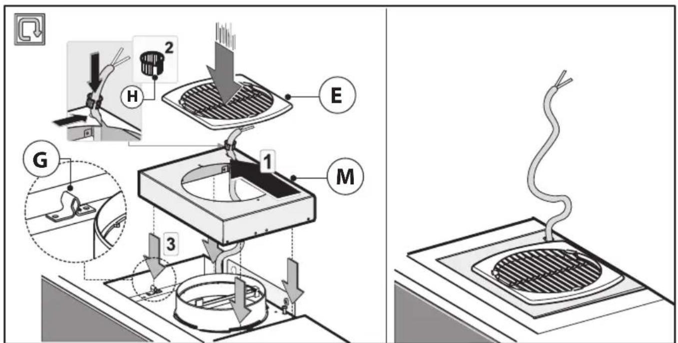
Fig.6
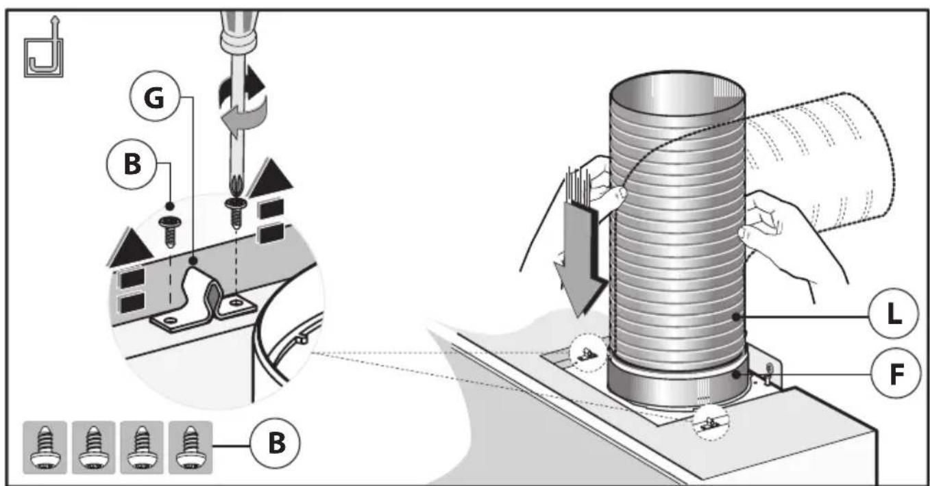
Fig.7
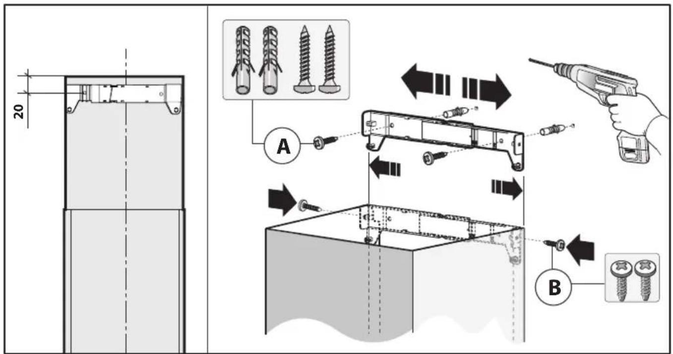
Fig.8
natural_image
Diagram of a cylindrical structure inside a transparent enclosure with an arrow indicating direction, no text or symbols present.Fig.9A
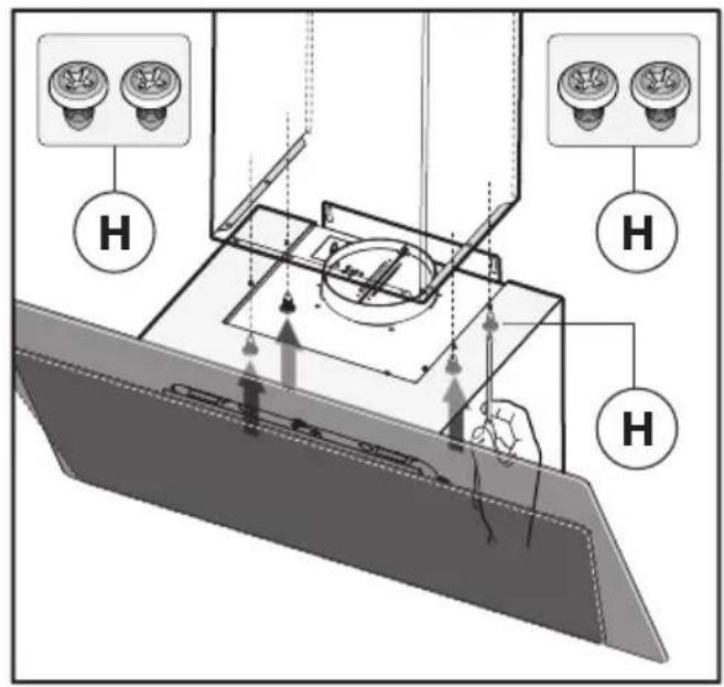
Fig.9B
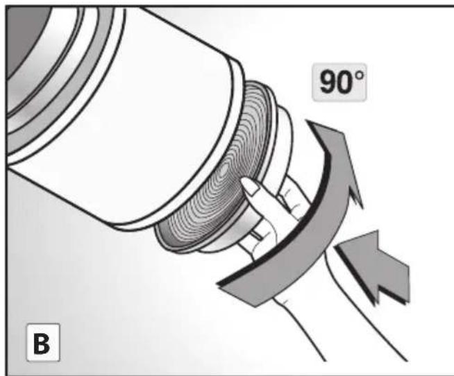
Fig.10
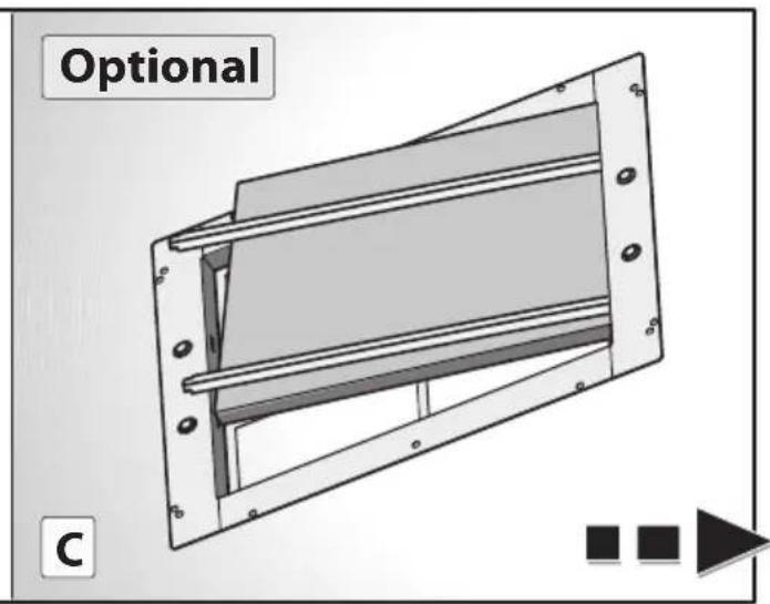
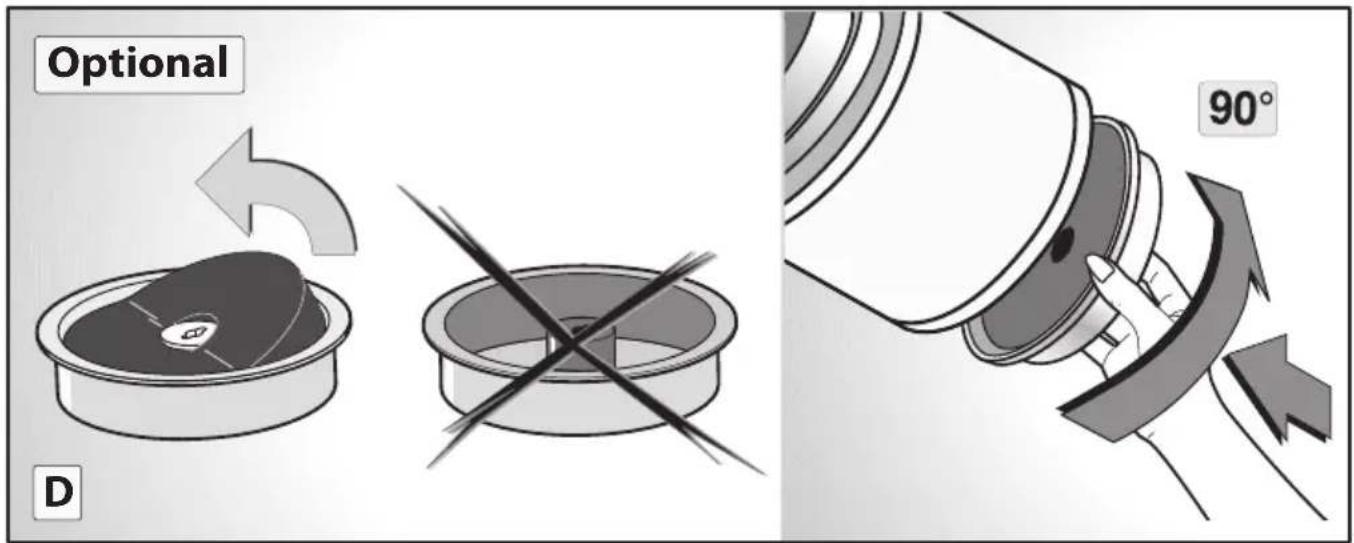
Fig.10
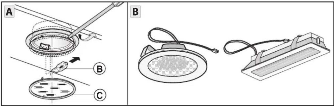
Fig.11
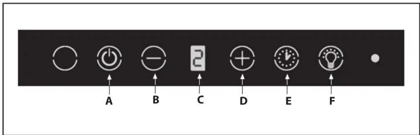
Fig.12
flowchart
graph TD
    A["Step A"] --> B["Step B"]
    B --> C["Step C"]
    C --> D["Step D"]
Fig.13
GENERALITÀ
• Commandes (Fig.12):
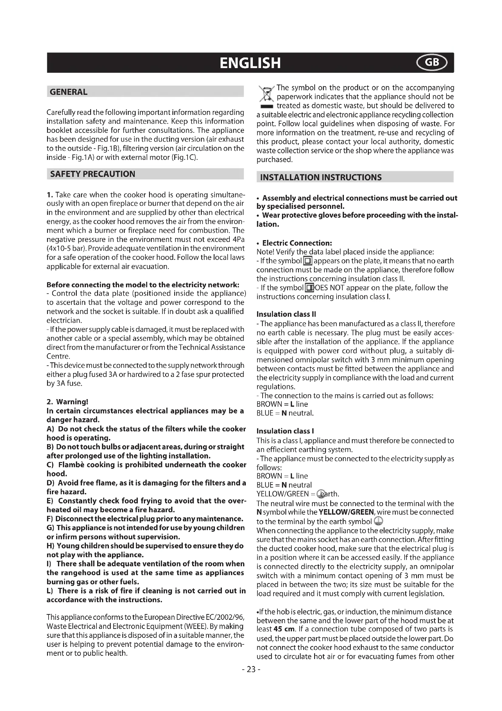
Carefully read the following important information regarding installation safety and maintenance. Keep this information booklet accessible for further consultations. The appliance has been designed for use in the ducting version (air exhaust to the outside - Fig.1B), filtering version (air circulation on the inside - Fig.1A) or with external motor (Fig.1C).
SAFETY PRECAUTION
- Take care when the cooker hood is operating simultaneously with an open fireplace or burner that depend on the air in the environment and are supplied by other than electrical energy, as the cooker hood removes the air from the environment which a burner or fireplace need for combustion. The negative pressure in the environment must not exceed 4Pa (4x10⁻⁵ bar). Provide adequate ventilation in the environment for a safe operation of the cooker hood. Follow the local laws applicable for external air evacuation.
Before connecting the model to the electricity network:
- Control the data plate (positioned inside the appliance) to ascertain that the voltage and power correspond to the network and the socket is suitable. If in doubt ask a qualified electrician.
- If the power supply cable is damaged, it must be replaced with another cable or a special assembly, which may be obtained direct from the manufacturer or from the Technical Assistance Centre.
- This device must be connected to the supply network through either a plug fused 3A or hardwired to a 2 fase spur protected by 3A fuse.
2. Warning!
In certain circumstances electrical appliances may be a danger hazard.
A) Do not check the status of the filters while the cooker hood is operating.
B) Do not touch bulbs or adjacent areas, during or straight after prolonged use of the lighting installation.
C) Flambè cooking is prohibited underneath the cooker hood.
D) Avoid free flame, as it is damaging for the filters and a fire hazard.
E) Constantly check food frying to avoid that the overheated oil may become a fire hazard.
F) Disconnect the electrical plug prior to any maintenance.
G) This appliance is not intended for use by young children or infirm persons without supervision.
H) Young children should be supervised to ensure they do not play with the appliance.
I) There shall be adequate ventilation of the room when the rangehood is used at the same time as appliances burning gas or other fuels.
L) There is a risk of fire if cleaning is not carried out in accordance with the instructions.
This appliance conforms to the European Directive EC/2002/96, Waste Electrical and Electronic Equipment (WEEE). By making sure that this appliance is disposed of in a suitable manner, the user is helping to prevent potential damage to the environment or to public health.

The symbol on the product or on the accompanying paperwork indicates that the appliance should not be treated as domestic waste, but should be delivered to a suitable electric and electronic appliance recycling collection point. Follow local guidelines when disposing of waste. For more information on the treatment, re-use and recycling of this product, please contact your local authority, domestic waste collection service or the shop where the appliance was purchased.
INSTALLATION INSTRUCTIONS
- Assembly and electrical connections must be carried out by specialised personnel.
- Wear protective gloves before proceeding with the installation.
• Electric Connection:
Note! Verify the data label placed inside the appliance:
- If the symbol ☐ appears on the plate, it means that no earth connection must be made on the appliance, therefore follow the instructions concerning insulation class II.
- If the symbol ☐OES NOT appear on the plate, follow the instructions concerning insulation class I.
Insulation class II
- The appliance has been manufactured as a class II, therefore no earth cable is necessary. The plug must be easily accessible after the installation of the appliance. If the appliance is equipped with power cord without plug, a suitably dimensioned omnipolar switch with 3 mm minimum opening between contacts must be fitted between the appliance and the electricity supply in compliance with the load and current regulations.
- The connection to the mains is carried out as follows:
BROWN = L line
BLUE = N neutral.
Insulation class I
This is a class I, appliance and must therefore be connected to an efficient earthing system.
- The appliance must be connected to the electricity supply as follows:
BROWN = L line
BLUE = N neutral
YELLOW/GREEN = Earth.
The neutral wire must be connected to the terminal with the N symbol while the YELLOW/GREEN, wire must be connected to the terminal by the earth symbol 🌐
When connecting the appliance to the electricity supply, make sure that the mains socket has an earth connection. After fitting the ducted cooker hood, make sure that the electrical plug is in a position where it can be accessed easily. If the appliance is connected directly to the electricity supply, an omnipolar switch with a minimum contact opening of 3 mm must be placed in between the two; its size must be suitable for the load required and it must comply with current legislation.
- If the hob is electric, gas, or induction, the minimum distance between the same and the lower part of the hood must be at least 45 cm. If a connection tube composed of two parts is used, the upper part must be placed outside the lower part. Do not connect the cooker hood exhaust to the same conductor used to circulate hot air or for evacuating fumes from other
appliances generated by other than an electrical source.
- In the case of assembly of the appliance in the suction version prepare the hole for evacuation of the air.
- We recommend the use of an air exhaust tube which has the same diameter as the air exhaust outlet hole. If a pipe with a smaller diameter is used, the efficiency of the product may be reduced and its operation may become noisier.
Attention!
- Before proceeding with the installation, to be able to move the hood more easily, complete the following operations:
-
Remove the anti-grease filter by pulling the handle, as shown in figure 2 - phase 1.
-
If the product is equipped with activated charcoal filters (B-C), remove them as shown in figure 2 - phase 2B or 2C.
-
Unhook the small cupola M as shown in figure 2 - phase 4.
• Fixing to the wall (Fig.3):
- Mark the position of the lower side of the hood on the wall figure 3 - phase 1(taking into account the minimum distance required from the hob).
- Position the fixing template on the wall, making sure that the line coincides with the line previously made on the wall, as described in the preceding section.
- Mark and drill fixing holes figure 3 - phase 2.
- Fasten the 4 anchors and the 2 screws A-B without fully tightening them figure 3 - phase 2.
- Position the appliance on the wall and permanently secure it by pulling the 2 screws B figure 3 - phase 3-4 and the 2 locking screws B figure 3 - phase 5.
- When carrying out the fixing operations, use only screws and screw anchors suited to the type of wall (e.g. reinforced concrete, plasterboard etc.).
- If the screws and screw anchors are supplied with the appliance, make sure that they are suited to the type of wall to which the hood must be fixed.
- Fixing to the wall OPTIONAL ACCESSORIES (Fig.4):
This hood model can have optional levelling brackets which can be requested from your dealer.
- Mark the position of the lower side of the hood on the wall figure 3 - phase 1(taking into account the minimum distance required from the hob).
- Position the fixing template on the wall, making sure that the line coincides with the line previously made on the wall, as described in the preceding section.
- Mark and drill fixing holes figure 3 - phase 2.
- Take the two levelling brackets C and fix them to the hood support with the screws D as indicated in figure 4 - step 1. Do not tighten the 2 levelling screws D.
- Take the appliance and hang it on the two screws B figure 4 - step 2.
- Align the appliance horizontally by adjusting the two levelling screws D figure 4 - step 3.
- When you have finished the adjustment, tighten the 2 screws B figure 4 - step 4 and mount the hood on the wall permanently using the two safety screws B figure 4 - step 5.
- When carrying out the fixing operations, use only screws and screw anchors suited to the type of wall (e.g. reinforced concrete, plasterboard etc.).
If the screws and screw anchors are supplied with the appliance, make sure that they are suited to the type of wall to which the hood must be fixed.
- Filtering version
- Unhook the small cupola M and remove the grille E (Fig. 5).
- Pass the power supply cable through the slots of the small cupola M as shown in Fig. 6.
- Take the fairlead H and position it between the power supply cable and the slot.
- Fasten the small cupola M and the grille E making sure that is it perfectly hooked on to the fastening pins G. (Fig. 6).
The filters must be applied to the suction unit positioned inside the hood. They must be centred by turning them 90 degrees until the stop catch is tripped (Fig.10B).
- Optional accessories
This model may have decorative ducts as optional accessories - ask your retailer for information.
Before installing decorative flues it is necessary to remove the small cupola and loosen the 4 screws B that lock the fastening pins G as shown in Fig.7.
- Installation of models with decorative ducts - extractor hood
Make sure the electrical power supply is within the measurements of the decorative connector.
Connect flange F to the air exhaust hole using flexible hose L (Fig.7).
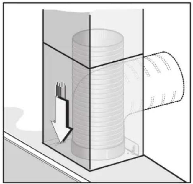
Adjust the width of the support bracket of the top connector (Fig. 8). Then fix it to the ceiling so that it is on the same axis as the hood using screws A and observing the distance from the ceiling shown in (Fig. 8). Slide the top connector inside the lower duct and place this on the body (Fig. 9).
- Secure the lower decorative chimney to the hood using the supplied screws H (Fig.9B).
Pull out the top duct as far as the bracket and secure it using screws B (Fig. 8).
To transform the hood from a ducting version into a filtering version, ask your dealer for the charcoal filters and follow the installation instructions.
- Filter hood:
Please note:
-In order to transform the hood from EXTRACTOR HOOD into FILTER HOOD the active carbon filters must be ordered at your distributor as accessory.
We have 3 different types of Kit, one with non-regenerable active carbon filters (Fig.10B) and the other one with regenerable active charcoal filters (washable) (Fig.10C - Fig.10D).
- Depending on the model one owns, the CIRCULAR active carbon filters must be applied to the suction unit located inside the hood, centring them and rotating them by 90 degrees until they snap into place (Fig.10B), to replace them perform the operation in reverse order.
- For WASHABLE regenerable activated carbon filters (Fig.10C), follow the assembly instructions contained in the KIT.
- For the WASHABLE CIRCULAR regenerable active carbon filters (Fig.10D), remove the pad and follow the instructions in the USE AND MAINTENANCE paragraph, "regenerable active carbon filters".
USE AND MAINTENANCE
- We recommend that the cooker hood is switched on before any food is cooked. We also recommend that the appliance is left running for 15 minutes after the food is cooked, in order to thoroughly eliminate all contaminated air. The effective performance of the cooker hood depends on constant maintenance; the anti-grease filter and the active carbon filter both require special attention.
- The anti-grease filter is responsible retaining the grease
particles suspended in the air, therefore it is subject to clogging with variable frequency according to the use of the appliance.
- To prevent the danger of possible fires, at least every 2 months one must wash the anti-grease filters by hand using non-abrasive neutral liquid detergents or in the dishwasher at low temperatures and on short cycles.
- After a few washes, colour alterations may occur. This does not give the right to claim their replacement.
- The active carbon filters are used to purify the air that is sent back into the room and its function is to mitigate the unpleasant odours produced by cooking.
- The non-regenerable active carbon filters must be replaced at least every 4 months. The saturation of the active charcoal depends on the more or less prolonged use of the appliance, on the type of kitchen and on the frequency with which anti-grease filter is cleaned.
- Regenerable active charcoal filters must be washed by hand, with non abrasive neutral detergents, or in the dishwasher at a maximum temperature of 65^ C (the washing cycle must be complete without dishware). Remove excess water without damaging the filter, remove the plastic parts, and let the mat dry in the oven for at least 15 minutes approximately at a maximum temperature of 100^ C. To keep the regenerable charcoal filter functioning efficient this operation must be repeated every 2 months. These must be replaced at least every 3 years or when the mat is damaged.
- Before remounting the anti-grease filters and the regenerable active charcoal filters it is important that they are completely dry.
- Clean the hood frequently, both internally and externally, using a cloth dampened with denatured alcohol or neutral liquid detergents that are non abrasive.
- The lighting .system is designed for use during cooking and not for the prolonged general lighting of the room. The prolonged use of the lighting system significantly decreases the average duration of the bulbs.
- If the appliance is equipped with courtesy lights it is possible to use them for general room lighting for a prolonged amount of time.
- Attention: the non compliance with the hood cleaning warnings and with the replacement and cleaning of the filters entails risk of fires. One therefore recommends keeping to the suggested instructions.
- Replacing halogen light bulbs (Fig.11A):
To replace the halogen light bulbs B, remove the glass pane C using a lever action on the relevant cracks. Replace the bulbs with new ones of the same type. Caution: do not touch the light bulb with bare hands.
- Replacing LED lamps (Fig.11B):
If the appliance version is with LED lamps, the intervention of a specialised technician is necessary to replace them.
- Commands (Fig.12):
NOTE: with this command it is also possible to control the appliance using a remote control, to be requested as an accessory.
A Button = Switches the hood on/off. The equipment switches on at the 1st speed.
B Button = Decreases motor speed.
C Display = Shows the selected motor speed and timer activation/intense speed/filter warning.
D Button = Increases motor speed.
Pressing the 4th speed button engages the intense function for 6 minutes, then the equipment goes back to working at the speed at which it was activated. During this function, the number 4 flashes on the display.
- If you wish to deactivate the function before the 6 minutes, press the B button.
Attention! Some models only work up to the 3rd speed and, therefore, do not have the intense function.
E Button = Pressing this button activates the Timer function even with any of the 1-2-3 speeds engaged (except the Intense function speed). When the Timer function is active, the set speed must flash on the display when the timer is activated.
After 15 minutes, at the end of the countdown, the hood switches off (motor and any lights remain on).
If the intense speed is engaged, the Timer cannot be activated.
- If you wish to deactivate the function before the 15 minutes, press the E button.
F Button = Switches the lights on/off.
- Anti-grease/active charcoal filters saturation:
- After 30 h of operation, when the C display flashes, alternating the working speed with the letter F (i.e. 2 and F), this means that you need to wash the anti grease filters.
- After 120 h of operation, when the C display flashes, alternating the working speed with the letters C/F (i.e. 2 and C/F), this means that you need to wash or replace the charcoal filters.
- Once you have repositioned the clean filter, you need to reset the electronic memory with the hood on, pressing the B button for about 3 seconds.
After that time, the letter E appears on the display (reset confirmed) and the hood switches off.
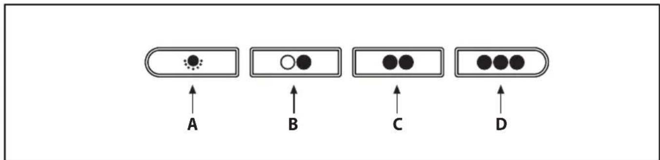
- Mechanical controls (Fig.13): the symbols are as follows:
A= LIGHT / ON-OFF key
B= OFF /FIRST SPEED key
C= SECOND SPEED key
D = THIRD SPEED key
If the hood is shut off at first, second or third speed, when it is turned back on, it will start at the same speed it was in when switched off.
CUSTOMER ASSISTANCE SERVICE
Before contacting the Technical Assistance Service.
If the product does not operate at all, we advise you to:
- Check that the plug has been inserted into the power socket correctly.
If you cannot identify the cause of the operating anomaly: switch off the appliance (do not subject it to rough treatment) and contact the Assistance Service.
PRODUCT SERIAL NUMBER. Where can I find it?
It is important that you inform the Assistance Service of your product code and its serial number (a 16-character code which begins with the number 3); this can be found on the guarantee certificate or on the data plate located inside the appliance.
This will help to avoid wasted journeys being made by technicians, thereby (and most significantly) saving the corresponding callout charges.
THE MANUFACTURER DECLINES ALL RESPONSIBILITY FOR EVENTUAL DAMAGES CAUSED BY BREACHING THE ABOVE WARNINGS.
ALGEMEEN
INSTALLATIE INSTRUCTIES
Tecla F = Acende/desliga as luzes.
C= tast for ANDEN HASTIGHED
D = tast for TREDJE HASTIGHED
GUL/GR∅NN = jording.
Den nøytrale tråden må koples til pluggen med symbolet N mens den GR∅NN/GULE, tråden måkoples til pluggen nær jordingssymbolet
A= tast for LYS / ON-OFF
B= tast for OFF / F∅RSTE HASTIGHET
C= tast for ANDRE HASTIGHET
D = tast for TREDJE HASTIGHET
Tasta F = Aprinde/stinge luminile.
natural_image
Stylized black-and-white graphic with a plant and star-like circles above, resembling a logo or emblem (no text or symbols)
natural_image
Black-and-white map of Europe showing countries in Europe with some shaded regions (no text or labels)3LIK1969


- GENERALITÀ
- SAFETY PRECAUTION
- Before connecting the model to the electricity network:
- Warning!
- INSTALLATION INSTRUCTIONS
- • Electric Connection:
- Insulation class II
- Insulation class I
- Attention!
- Please note:
- USE AND MAINTENANCE
- CUSTOMER ASSISTANCE SERVICE
- PRODUCT SERIAL NUMBER. Where can I find it?
- THE MANUFACTURER DECLINES ALL RESPONSIBILITY FOR EVENTUAL DAMAGES CAUSED BY BREACHING THE ABOVE WARNINGS.
- ALGEMEEN
- INSTALLATIE INSTRUCTIES
Brand : HOOVER
Model : HDMC9800LB
Category : Range hood