
DKC 2020 - Range hood BLOMBERG - Free user manual and instructions
Find the device manual for free DKC 2020 BLOMBERG in PDF.
| Product Type | Range Hood |
| Brand | Blomberg |
| Model | DKC 2020 |
| Installation | Telescopic chimney, exhaust or recirculating version |
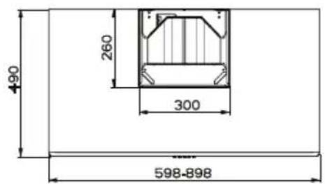
| Approximate Dimensions | 60 cm width, 50 cm depth, variable height |
| Approximate Weight | 10 kg |
| Power Supply | 220-240 V ~ 50 Hz |
| Motor Power (estimated) | 200 W |
| Lighting | 2 incandescent lamps, 40 W max |
| Suction Speeds | 3 speeds + intensive speed |
| Controls | Mechanical buttons with LED indicators |
| Grease Filters | Self-supporting metal, dishwasher-safe |
| Charcoal Filter | Replace every 4 months (not included, optional) |
| Air Outlet Diameter | 120 mm or 150 mm |
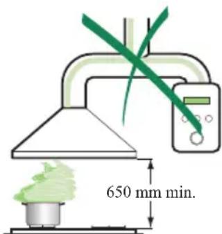
| Minimum Distance from Cooking Surface | 650 mm |
| Noise Level (estimated) | 55 dB(A) at medium speed |
| Airflow (estimated) | 600 m³/h |
| Maintenance | Clean exterior with a damp cloth and mild detergent; washable metal filters every 2 months |
| Safety | Unplug before maintenance; do not use with open flames; safety distance 650 mm |
| Usage | Household use only, to eliminate cooking odors |
Frequently Asked Questions - DKC 2020 BLOMBERG
User questions about DKC 2020 BLOMBERG
0 question about this device. Answer the ones you know or ask your own.
Ask a new question about this device
Download the instructions for your Range hood in PDF format for free! Find your manual DKC 2020 - BLOMBERG and take your electronic device back in hand. On this page are published all the documents necessary for the use of your device. DKC 2020 by BLOMBERG.
USER MANUAL DKC 2020 BLOMBERG
RECOMMENDATIONS AND SUGGESTIONS 4
CHARACTERISTICS 5
INSTALLATION 6
USE 9
MAINTENANCE 11
SOMMAIRE
FR
CONSEILS ET SUGGESTIONS 12
CHARACTERISTIQUES 13
INSTALLATION 14
UTILISATION 17
ENTRETIEN 19
INHALTSVERZEICHNIS
DE
The Instructions for Use apply to several versions of this appliance. Accordingly, you may find descriptions of individual features that do not apply to your specific appliance.
INSTALLATION
- The manufacturer will not be held liable for any damages resulting from incorrect or improper installation.
- The minimum safety distance between the cooker top and the extractor hood is 650~mm .
- Check that the mains voltage corresponds to that indicated on the rating plate fixed to the inside of the hood.
- For Class I appliances, check that the domestic power supply guarantees adequate earthing.
Connect the extractor to the exhaust flue through a pipe of minimum diameter 120mm . The route of the flue must be as short as possible.
- Do not connect the extractor hood to exhaust ducts carrying combustion fumes (boilers, fireplaces, etc.).
- If the extractor is used in conjunction with non-electrical appliances (e.g. gas burning appliances), a sufficient degree of aeration must be guaranteed in the room in order to prevent the backflow of exhaust gas. The kitchen must have an opening communicating directly with the open air in order to guarantee the entry of clean air.
USE
- The extractor hood has been designed exclusively for domestic use to eliminate kitchen smells.
- Never use the hood for purposes other than for which it has been designed.
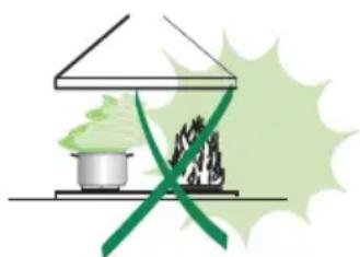
- Never leave high naked flames under the hood when it is in operation.
- Adjust the flame intensity to direct it onto the bottom of the pan only, making sure that it does not engulf the sides.
- Deep fat fryers must be continuously monitored during use: overheated oil can burst into flames.
- Do not flambe under the range hood; risk of fire
- This appliance is not intended for use by persons (including children) with reduced physical, sensory or mental capabilities, or lack of experience and knowledge, unless they have been given supervision or instruction concerning use of the appliance by a person responsible for their safety.
Children should be supervised to ensure that they do not play with the appliance
MAINTENANCE
- Switch off or unplug the appliance from the mains supply before carrying out any maintenance work.
- Clean and/or replace the Filters after the specified time period.
- Clean the hood using a damp cloth and a neutral liquid detergent.
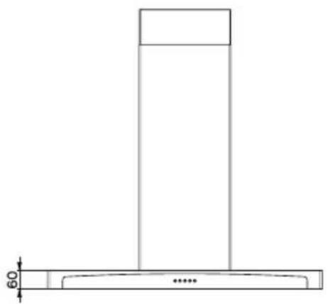
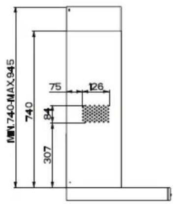
Dimensions
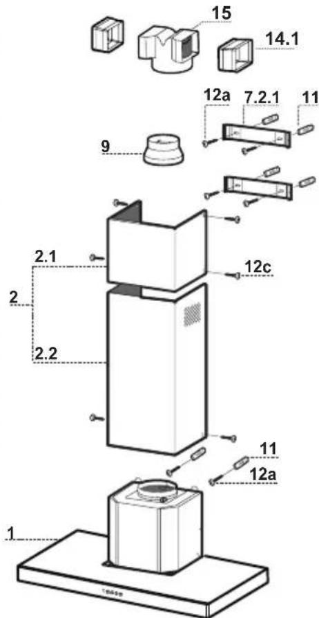
Components
| Ref. | Q.ty | Product | Components |
| 1 | 1 | Hood Body, complete with: Controls, Light, Blower, Filters | |
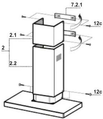
| 2 | 1 | Telescopic Chimney comprising: | |
| 2.1 | 1 | Upper | Section |
| 2.2 | 1 | Lower | Section |
| 9 | 1 | Reducer Flange ø 150-120 mm | |
| 14.1 | 2 | Air Outlet Connection Extension | |
| 15 | 1 | Air Outlet Connection | |
| Ref. | Q.ty | Installation | Components |
| 7.2.1 | 2 | Upper Chimney Section Fixing Brackets | |
| 11 | 6 | Wall | Plugs |
| 12a | 6 | Screws 4,2 x 44,4 | |
| 12c | 6 | Screws 2,9 x 9,5 | |
| Q.ty | Documentation | ||
| 1 | Instruction Manual | ||
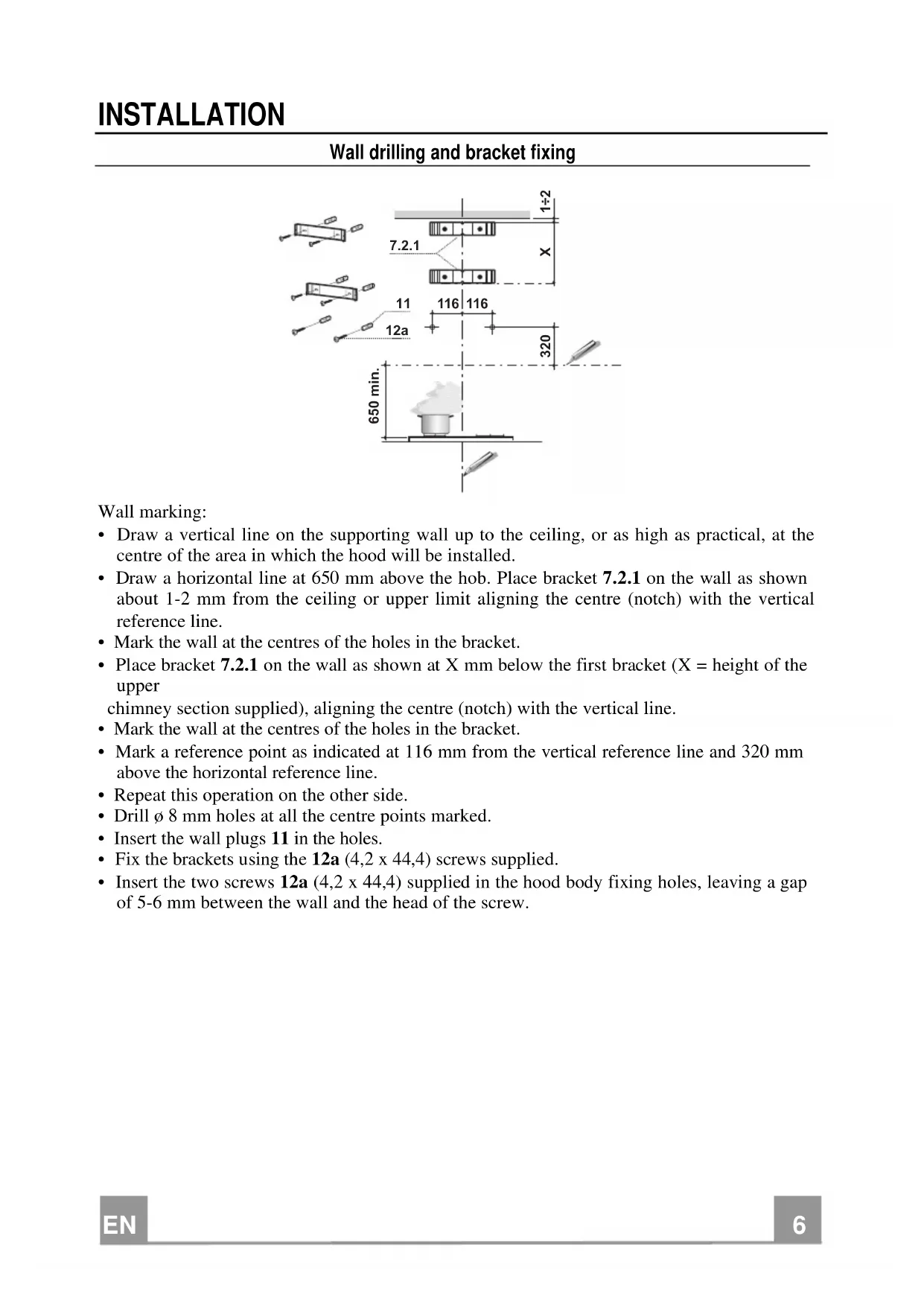
Wall drilling and bracket fixing
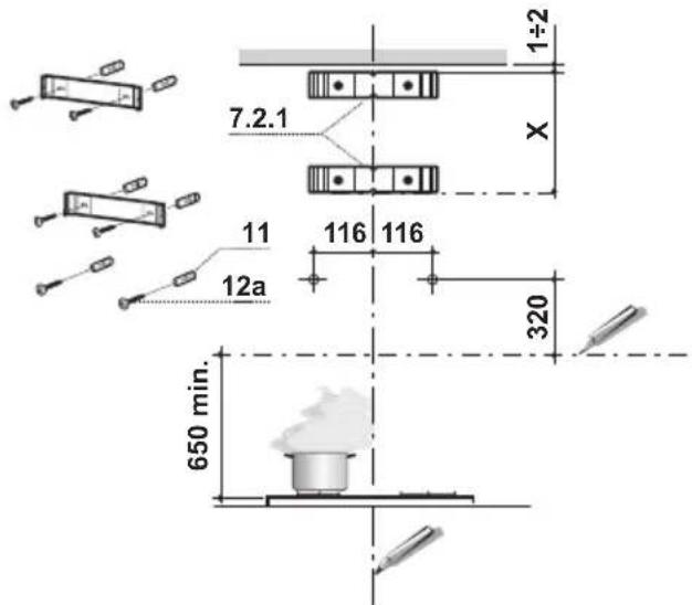
Wall marking:
- Draw a vertical line on the supporting wall up to the ceiling, or as high as practical, at the centre of the area in which the hood will be installed.
- Draw a horizontal line at 650mm above the hob. Place bracket 7.2.1 on the wall as shown about 1 - 2mm from the ceiling or upper limit aligning the centre (notch) with the vertical reference line.
- Mark the wall at the centres of the holes in the bracket.
- Place bracket 7.2.1 on the wall as shown at X mm below the first bracket ( X = height of the upper chimney section supplied), aligning the centre (notch) with the vertical line.
- Mark the wall at the centres of the holes in the bracket.
- Mark a reference point as indicated at 116mm from the vertical reference line and 320mm above the horizontal reference line.
- Repeat this operation on the other side.
- Drill 8mm holes at all the centre points marked.
- Insert the wall plugs 11 in the holes.
Fix the brackets using the 12a (4,2 x 44,4) screws supplied. - Insert the two screws 12a (4,2 x 44,4) supplied in the hood body fixing holes, leaving a gap of 5 - 6mm between the wall and the head of the screw.
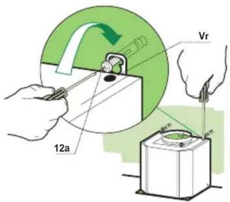
Mounting the hood body
- Before attaching the hood body, tighten the two screws Vr located on the hood body mounting points.
- Hook the hood body onto the screws 12a.
- Fully tighten the support screws 12a.
- Adjust the screws Vr to level the hood body.
Connections
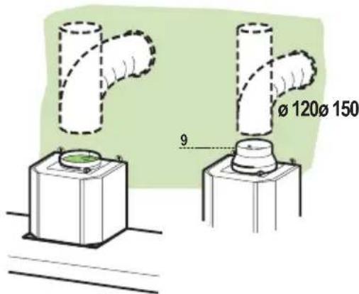
DUCTED VERSION AIR EXHAUST SYSTEM
When installing the ducted version, connect the hood to the chimney using either a flexible or rigid pipe 150 or 120mm the choice of which is left to the installer.
- To install a 120mm air exhaust connection, insert the reducer flange 9 on the hood body outlet.
Fix the pipe in position using sufficient pipe clamps (not supplied). - Remove possible charcoal filters.
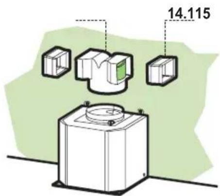
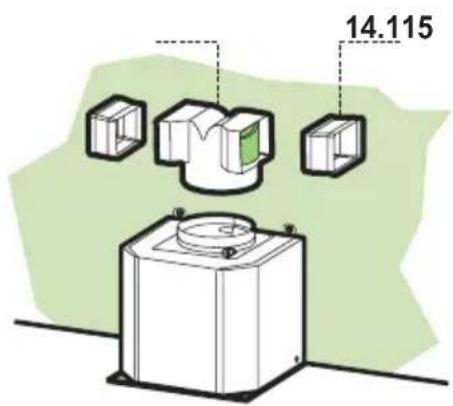
RECIRCULATION VERSION AIR OUTLET
- Push fit connection 15 onto the hood body outlet.
- Insert the connection extension pieces laterally 14.1 in connection 15.
- Make sure that the outlet of the extension pieces 14.1 is horizontally and vertically aligned with the chimney outlets. If this is not the case, adjust the position by either reversing the connection extension pieces 14.1 and then reassemble as described previously.
- Ensure that the activated charcoal filters have been inserted.
ELECTRICAL CONNECTION
- Connect the hood to the mains through a two-pole switch having a contact gap of at least 3mm .
- Remove the grease filters (see paragraph Maintenance) being sure that the connector of the feeding cable is correctly inserted in the socket placed on the side of the fan.
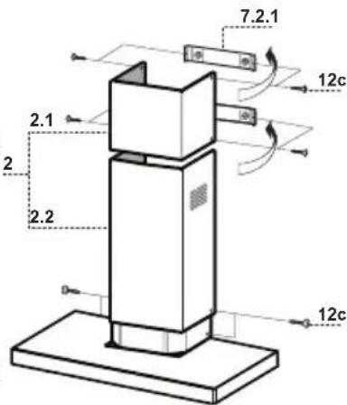
Chimney assembly
Upper exhaust Chimney
- Slightly widen the two sides of the upper chimney and hook them behind the brackets 7.2.1, making sure that they are well seated.
- Secure the sides to the brackets using the 4 screws 12c (2,9 x 9,5) supplied.
Lower exhaust Chimney
- Slightly widen the two sides of the chimney and hook them between the upper chimney and the wall, making sure that they are well seated.
Fix the lower part laterally to the hood body using the 2 screws 12c (2,9× 9,5) supplied.
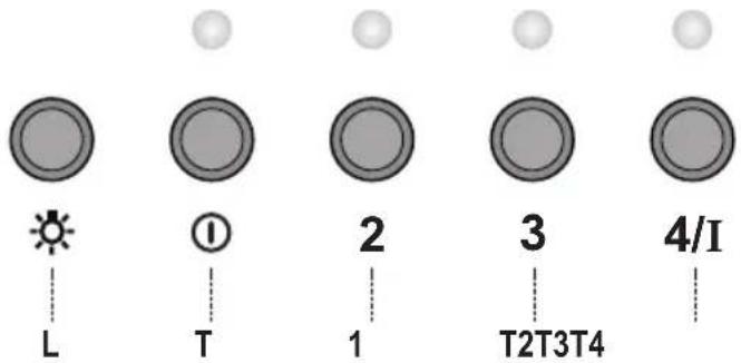
Control panel
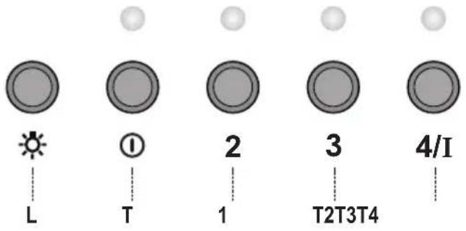
| KEY | LED | FUNCTIONS | |
| L 0/1 Light | Turns lighting on and off. | ||
| T1 | 0/1 Motor | on | First speed. |
| When pressed for about 1 seconds the motor is switched off. | |||
| T2 | Speed | on | Second speed. |
| T3 | Speed | on | Third speed. |
| T4 | Speed | Fixed | Max. speed |
| Flashing | Intensive speed. | ||
| Suitable for the strongest cooking vapours and odours. The func- tion becomes active when the button is pushed for about 2 sec- ons. After 10 minutes of functioning it turns off automatically. | |||
| This function can be interrupted by means of pressing any of the buttons. | |||
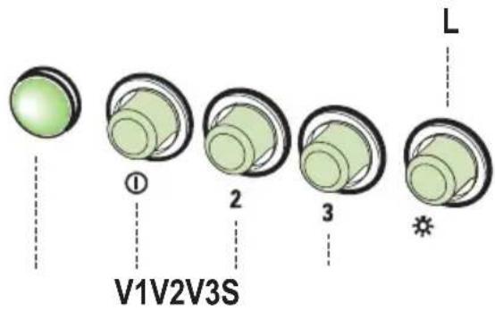
L Light Switches the lighting system on and off.
S Led Motor running led.
V1 Motor Switches the extractor motor on and off at low speed. Used to provide a continu- uos and silent air change in the presence of light cooking vapours.
V2 Speed Medium speed, suitable for most operating conditions given the optimum treated air floss/noise level ratio.
V3 Intensive Maximum speed, used for eliminating the highest cooking vapour emission, including long periods.
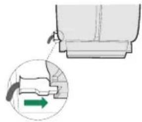
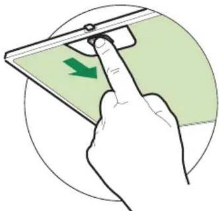
Grease filters
CLEANING METAL SELF- SUPPORTING GREASE FILTERS
- The filters must be cleaned every 2 months of operation, or more frequently for particularly heavy usage, and can be washed in a dishwasher.
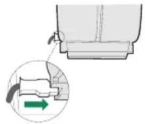
- Remove the filters one at a time by pushing them towards the back of the group and pulling down at the same time.
- Wash the filters, taking care not to bend them. Allow them to dry before refitting.
- When refitting the filters, make sure that the handle is visible on the outside.
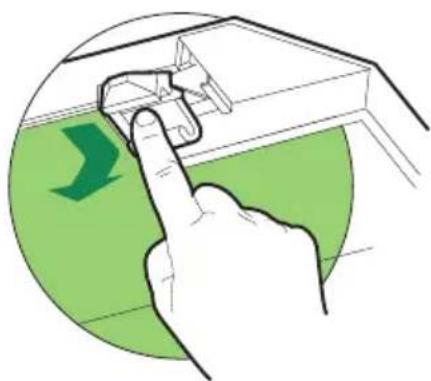
Activated charcoal filter (Recirculation version)
REPLACING THE ACTIVATED CHARCOAL FILTER
- The filter is not washable and cannot be regenerated, and must be replaced approximately every 4 months of operation, or more frequently for particularly heavy usage.
- Remove the metal grease filters.
- Remove the saturated activated carbon filter by releasing the fixing hooks.
- Fit the new filter by hooking it into its seating.
- Refit the metal grease filters.
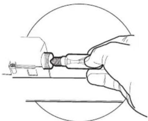
Lighting
LIGHT REPLACEMENT
40 W incandescent light.
- Remove the metal grease filters.
- Unscrew the bulbs and replace them with new ones having the same characteristics.
- Replace the metal grease filters.
REEMPLACEMENT LAMPES
Ref. Installatieonderdelen
BbIyCK BO3dyxA N3 BCACbIBAIOUeB bITJxKIN
JIy yCTaHOBKn BCacbIBaHOIeB bITJXKN COeINHHTb ee c BbIpyCKHO Tpy6oN JecTKO HJIN rH6KO Tpy6KO IHaMeTpOM 150 HJN 120 MM, TII KOtOpO MoKcT Bbl-6paTB MOHTaKHNK.
IIO coeHHHnpyok0 120 MM BCTABINb IepexOJIbHn
3aKpeHITb Tpy6ky COOTBeTCTByIOHMN Tpy6HbIMn 3aJHMaMH. Heo6XoIIMbI KpeIIeKHH MaTepHaJI He BXOINT B KOMIIJEKT.
BbHytb hJbTpbl OT 3aIIaxOB Ha aKTHBHOM yTJe.

BbIyCK BO3dYxA N3 ΦNttpUoUe BbITaXKn
Bbntb npyok 15 B BBnucKhoe OTBepCThe KopNyca BbITJKKN.
BcTaBnTb c 6oky Hacaikn IaTppy6ka 14.1 B IaTppy6ok 15.
IPOBepHTb,TO6bIBBnYCKHOEOTBepCTHe HacaIOK IIATpy6ka 14.1 COBIIaJIO C OTBepCTHmN IbIMOXOJa, KaIK IIO ROPn3OHTaJIN, TaK IN IO BepTHKaJIN. EcJIn Ke OHO He COBIIaJaET, IOMeHrTb MeCTaMn HaCaIKN IIATpy6ka 14.1 N yCTaHOBHTb BCE qactH, KaK OIIncAHO Bblie.
IIpoBepntb HaJIInuHne HJbTpa OT 3aIaxOB Ha aKTHB-HOM yIJe.
3NEKTPNUECKOE NOKNIQUOHEH
CoeHHHTb BbITKky c ceTeBbIM HaIIpJKeHHem, yCTaHOBBIByXIOJIIOCHbI BBIKIOuATEJIb C pa3BeJeHHem KOHTaKTOB He MeHee 3 MM.
CHaTb IpoTHBOXHPOBbIe HJIbTpBI (CMOTpHa3JeJ "YxoJ") H IpoBepHTb IIpaBnJIbHOCTb IOIOKeHHa pa3bema IITaIOIIeRo Ka6eJI B pO3ETKE BBITJIKN
yctahOBka dbIMOXOda
BepxnnIbIMoxoI
Cnerka pa3BecTH IBe 6OKOBbIe KpOMKn IbIMOXOJa, 3aIIeINHTb Hx 3a cKO6bl 7.2.1 IN BHO8b CBeCTH Hx IO yIIOpa.
3aKpeINb IbIMOXoI c6Oky 4 BXOJIINHM B KOMJIeKT BHTaMn 12c (2,9 x 9.5).
HnKHHn IbIMoXoI
CJIeKa pa3BecTH IBe 6OKOBbIe KpOMKn IbIMOXOJa, 3aIeHITb HX MEJy BEPHM IbIMOXOOM H CTeHOH H BHOB CBecTH HX IO YIopa.
3aKpeHb HxHHIO qactb bIMoxOa c60ky K Kopny CBITJIKBxOJIHMN B KOMIIJEKT 2 BHHTAMN 12c (2,9 x 9,5).
Panaelb ynpaBneHnA
The symbol on the product or on its packaging indicates that this product may not be treated as household waste. Instead it shall be handed over to the applicable collection point for the recycling of electrical and electronic equipment. By ensuring this product is disposed of correctly, you will help prevent potential negative consequences for the environment and human health, which could otherwise be caused by inappropriate waste handling of this product. For more detailed information about recycling of this product, please contact your local city office, your household waste disposal service or the shop where you purchased the product.


- SOMMAIRE
- FR
- INHALTSVERZEICHNIS
- DE
- INSTALLATION
- USE
- MAINTENANCE
- Wall drilling and bracket fixing
- Wall marking:
- Mounting the hood body
- Connections
- DUCTED VERSION AIR EXHAUST SYSTEM
- RECIRCULATION VERSION AIR OUTLET
- ELECTRICAL CONNECTION
- Chimney assembly
- Upper exhaust Chimney
- Lower exhaust Chimney
- Grease filters
- CLEANING METAL SELF- SUPPORTING GREASE FILTERS
- Activated charcoal filter (Recirculation version)
- REPLACING THE ACTIVATED CHARCOAL FILTER
- Lighting
- LIGHT REPLACEMENT
- W incandescent light.
- REEMPLACEMENT LAMPES
- BbIyCK BO3dyxA N3 BCACbIBAIOUeB bITJxKIN
- BbIyCK BO3dYxA N3 ΦNttpUoUe BbITaXKn
- 3NEKTPNUECKOE NOKNIQUOHEH
- yctahOBka dbIMOXOda
- BepxnnIbIMoxoI
- HnKHHn IbIMoXoI
Brand : BLOMBERG
Model : DKC 2020
Category : Range hood