DKC 5020 L - Basket BLOMBERG - Free user manual and instructions
Find the device manual for free DKC 5020 L BLOMBERG in PDF.
User questions about DKC 5020 L BLOMBERG
0 question about this device. Answer the ones you know or ask your own.
Ask a new question about this device
Download the instructions for your Basket in PDF format for free! Find your manual DKC 5020 L - BLOMBERG and take your electronic device back in hand. On this page are published all the documents necessary for the use of your device. DKC 5020 L by BLOMBERG.
USER MANUAL DKC 5020 L BLOMBERG
Instructions Manual INDEX
RECOMMENDATIONS AND SUGGESTIONS 7
CHARACTERISTICS 8
INSTALLATION....9
USE 12
MAINTENANCE 14
Manuel d'Instructions SOMMAIRE
CONSEILS ET SUGGESTIONS....15
CARACTERISTIQUES....16
INSTALLATION....17
UTILISATION 20
ENTRETIEN 22
RECOMMENDATIONS AND SUGGESTIONS
INSTALLATION
- The manufacturer will not be held liable for any damages resulting from incorrect or improper installation.
- The minimum safety distance between the cooker top and the extractor hood is 650 mm.
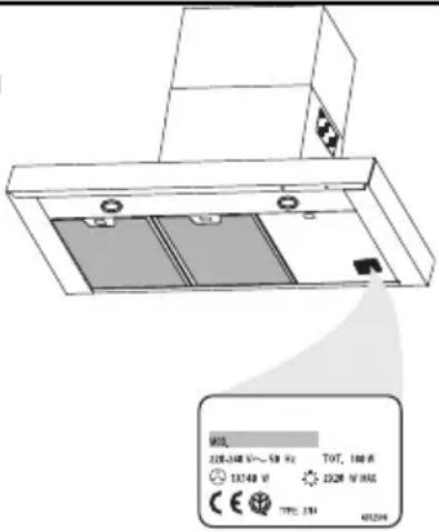
- Check that the mains voltage corresponds to that indicated on the rating plate fixed to the inside of the hood.
- For Class I appliances, check that the domestic power supply guarantees adequate earthing.
Connect the extractor to the exhaust flue through a pipe of minimum diameter 120 mm. The route of the flue must be as short as possible.
- Do not connect the extractor hood to exhaust ducts carrying combustion fumes (boilers, fireplaces, etc.).
- If the extractor is used in conjunction with non-electrical appliances (e.g. gas burning appliances), a sufficient degree of aeration must be guaranteed in the room in order to prevent the backflow of exhaust gas. The kitchen must have an opening communicating directly with the open air in order to guarantee the entry of clean air.
USE
- The extractor hood has been designed exclusively for domestic use to eliminate kitchen smells.
- Never use the hood for purposes other than for which it has been designed.
- Never leave high naked flames under the hood when it is in operation.
- Adjust the flame intensity to direct it onto the bottom of the pan only, making sure that it does not engulf the sides.
- Deep fat fryers must be continuously monitored during use: overheated oil can burst into flames.
- The hood should not be used by children or persons not instructed in its correct use.
MAINTENANCE
- Switch off or unplug the appliance from the mains supply before carrying out any maintenance work.
- Clean and/or replace the Filters after the specified time period.
- Clean the hood using a damp cloth and a neutral liquid detergent.
text_image
MAX 220-240 V~50 Hz TOT, 100 W 13240 V 220V W MAX TYPE: 1.94 M2004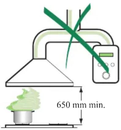
text_image
650 mm min.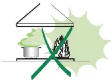
natural_image
Illustration of a cooking setup with a pot and a stove, crossed by a green ribbon (no text or symbols)Dimensions

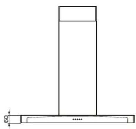
natural_image
Technical line drawing of a T-shaped structure with a base and top, showing dimension 60 (no text or symbols)
text_image
MIN 740-MAX 945 740 75 126 84 307
text_image
490 260 300 598-898Components
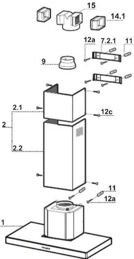
Ref. Q.ty Product Components
1 1 Hood Body, complete with: Controls, Light, Blower, Filters
2 1 Telescopic Chimney comprising:
2.1 1 Upper Section
2.2 1 Lower Section
9 1 Reducer Flange ø 150-120 mm
14.1 2 Air Outlet Connection Extension
15 1 Air Outlet Connection
Ref. Q.ty Installation Components
7.2.1 2 Upper Chimney Section Fixing Brackets
11 6 Wall Plugs
12a 6 Screws 4,2 x 44,4
12c 6 Screws 2,9 x 9,5
Q.ty Documentation
1 Instruction Manual
text_image
1 2.1 2.2 9 14.1 15 12a 7.2.1 11 12c 11 12a 1 100mmWall drilling and bracket fixing
text_image
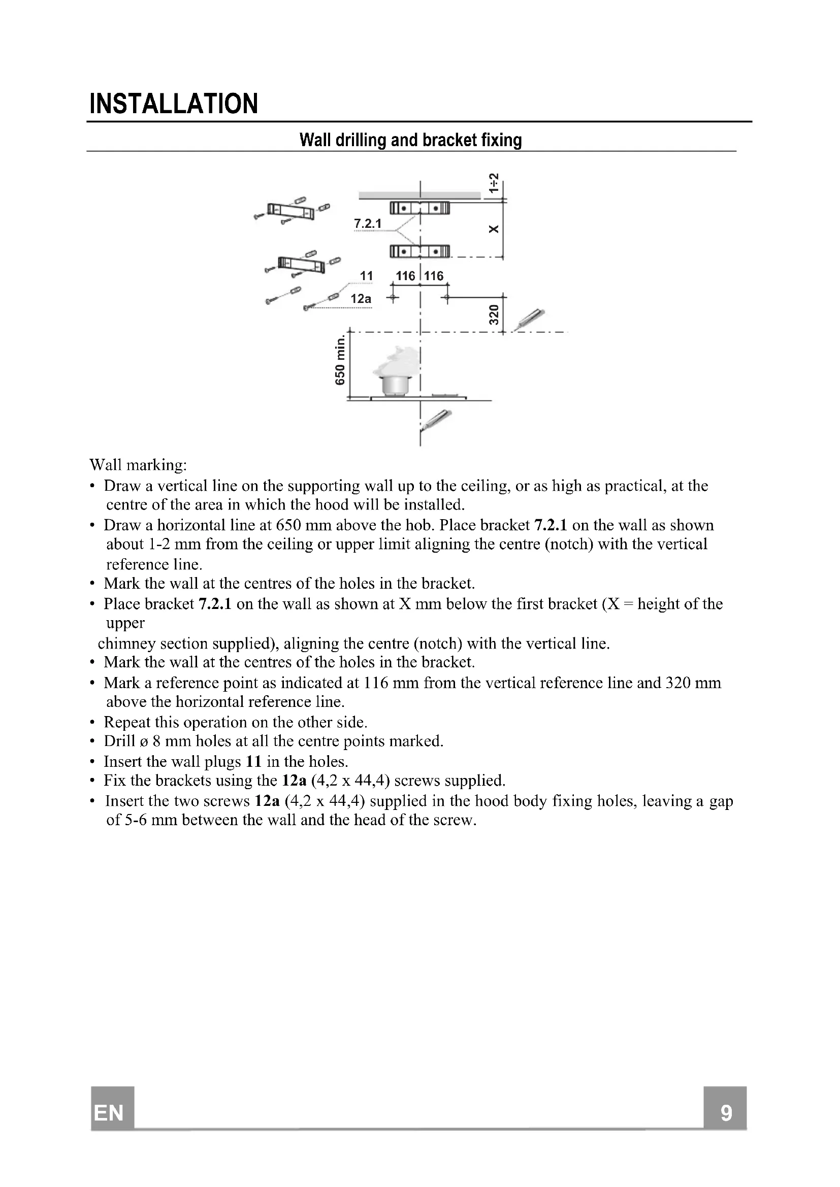
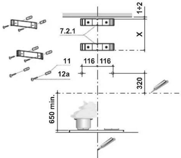
7.2.1 11 12a 116 116 320 650 min. 1÷2 XWall marking:
- Draw a vertical line on the supporting wall up to the ceiling, or as high as practical, at the centre of the area in which the hood will be installed.
- Draw a horizontal line at 650 mm above the hob. Place bracket 7.2.1 on the wall as shown about 1-2 mm from the ceiling or upper limit aligning the centre (notch) with the vertical reference line.
- Mark the wall at the centres of the holes in the bracket.
- Place bracket 7.2.1 on the wall as shown at X mm below the first bracket (X = height of the upper
chimney section supplied), aligning the centre (notch) with the vertical line. - Mark the wall at the centres of the holes in the bracket.
- Mark a reference point as indicated at 116 mm from the vertical reference line and 320 mm above the horizontal reference line.
- Repeat this operation on the other side.
- Drill 8 mm holes at all the centre points marked.
- Insert the wall plugs 11 in the holes.
• Fix the brackets using the 12a (4,2 x 44,4) screws supplied. - Insert the two screws 12a (4,2 x 44,4) supplied in the hood body fixing holes, leaving a gap of 5-6 mm between the wall and the head of the screw.
Mounting the hood body
- Before attaching the hood body, tighten the two screws Vr located on the hood body mounting points.
- Hook the hood body onto the screws 12a.
• Fully tighten support screws 12a. - Adjust screws Vr to level the hood body.
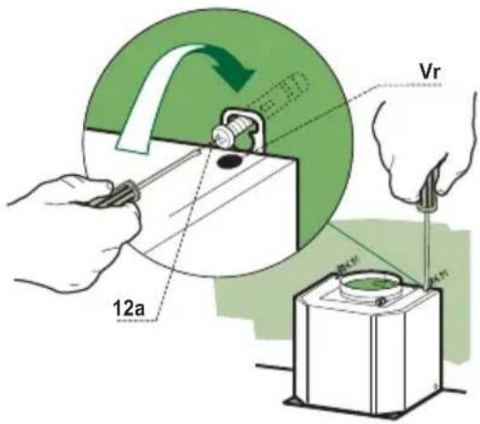
text_image
12a VrConnections
DUCTED VERSION AIR EXHAUST SYSTEM
When installing the ducted version, connect the hood to the chimney using either a flexible or rigid pipe 150 or 120 mm, the choice of which is left to the installer.
- To install a 120 mm air exhaust connection, insert the reducer flange 9 on the hood body outlet.
- Fix the pipe in position using sufficient pipe clamps (not supplied).
- Remove any activated charcoal filters.
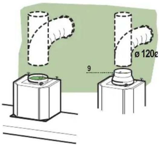
text_image
Ø 120c 9RECIRCULATION VERSION AIR OUTLET
- Push fit connection 15 onto the hood body outlet.
- Insert the connection extension pieces laterally 14.1 in connection 15.
- Make sure that the outlet of the extension pieces 14.1 is horizontally and vertically aligned with the chimney outlets. If this is not the case, adjust the position by either reversing the connection extension pieces 14.1 and then reassemble as described previously.
- Ensure that the activated charcoal filters have been inserted.
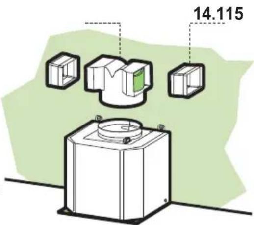
text_image
14.115ELECTRICAL CONNECTION
- Connect the hood to the mains through a two-pole switch having a contact gap of at least 3 mm.
- Remove the grease filters (see paragraph Maintenance) being sure that the connector of the feeding cable is correctly inserted in the socket placed on the side of the fan.
natural_image
Diagram showing a mechanical component with an inset view of a tool interacting with a green arrow (no text or symbols present)Flue assembly
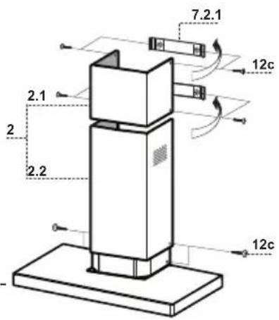
Upper exhaust flue
- Slightly widen the two sides of the upper flue and hook them behind the brackets 7.2.1, making sure that they are well seated.
- Secure the sides to the brackets using the 4 screws 12c (2,9 x 9,5) supplied.
Lower exhaust flue
- Slightly widen the two sides of the flue and hook them between the upper flue and the wall, making sure that they are well seated.
- Fix the lower part laterally to the hood body using the 2 screws 12c (2,9 x 9,5) supplied.
text_image
7.2.1 12c 2.1 2 2.2 12c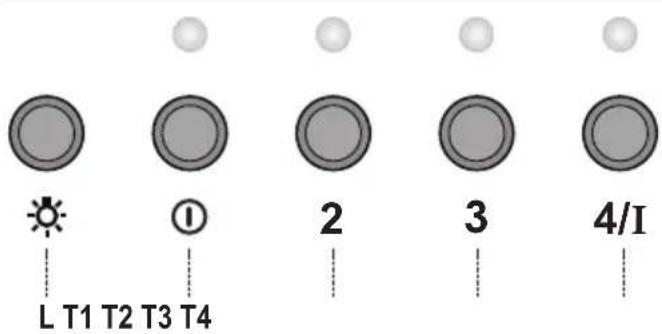
text_image
L T1 T2 T3 T4 ① 2 3 4/IControl panel
KEY LED FUNCTIONS
L 0/1 Light Turns lighting on and off.
T1 0/1 Motor on First speed.
When pressed for about 1 seconds the motor is switched off.
T2 Speed on Second speed.
T3 Speed on Third speed.
T4 Speed Fixed Max. speed
Flashing Intensive speed.
Suitable for the strongest cooking vapours and odours. The func-
tion becomes active when the button is pushed for about 2 seconds. After 10 minutes of functioning it turns off automatically. This function can be interrupted by means of pressing any of the buttons.
text_image
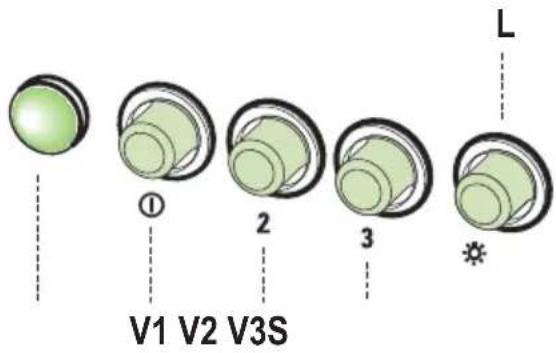
V1 V2 V3S LL Light Switches the lighting system on and off.
S Led Motor running led.
V1 Motor Switches the extractor motor on and off at low speed. Used to provide a continuous and silent air change in the presence of light cooking vapours.
V2 Speed Medium speed, suitable for most operating conditions given the optimum treated air flox/noise level ratio.
V3 Intensive Maximum speed, used for eliminating the highest cooking vapour emission, including long periods.
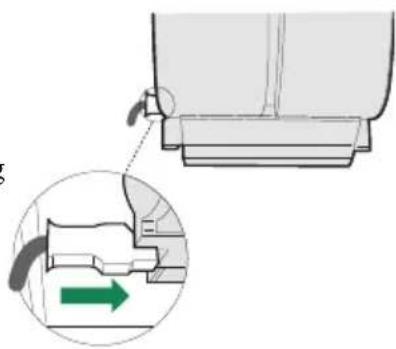
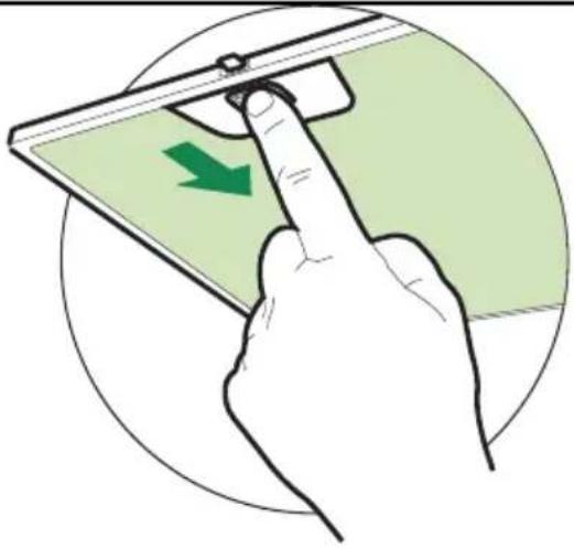
Grease filters
CLEANING METAL SELF- SUPPORTING GREASE FILTERS
- The filters must be cleaned every 2 months of operation, or more frequently for particularly heavy usage, and can be washed in a dishwasher.
- Remove the filters one at a time by pushing them towards the back of the group and pulling down at the same time.
- Wash the filters, taking care not to bend them. Allow them to dry before refitting.
- When refitting the filters, make sure that the handle is visible on the outside.
natural_image
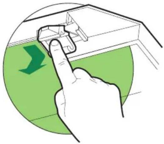
Illustration of a hand interacting with a device, showing a green arrow indicating direction (no text or symbols present)Activated charcoal filter (Recirculation version)
REPLACING THE ACTIVATED CHARCOAL FILTER
- The filter is not washable and cannot be regenerated, and must be replaced approximately every 4 months of operation, or more frequently for particularly heavy usage.
- Remove the metal grease filters
- Remove the saturated activated carbon filter by releasing the fixing hooks
• Fit the new filter by hooking it into its seating - Replace the metal grease filters.
natural_image
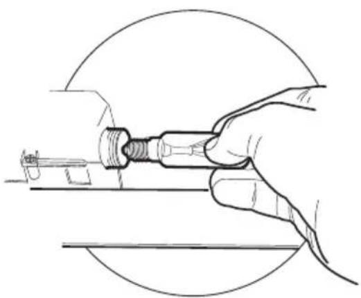
Illustration of a hand pressing down on a mechanical component with a green arrow indicating downward motion (no text or symbols)Lighting
LIGHT REPLACEMENT
40 W incandescent light.
- Remove the metal grease filters.
- Unscrew the bulbs and replace them with new ones having the same characteristics.
- Replace the metal grease filters.
natural_image
Line drawing of a hand holding a mechanical component, enclosed in a circular frame (no text or symbols)CONSEILS ET SUGGESTIONS
INSTALLATION
natural_image
Illustration of a cooking setup with a pot and smokestack, crossed by a green ribbon (no text or symbols)Encombrement

natural_image
Technical line drawing of a T-shaped structure with a base and top, showing dimension 60 (no text or symbols)
text_image
MIN 740-MAX 945 740 75 126 84 307
text_image
490 260 300 598-898Composants
natural_image
Diagram showing a mechanical component with an inset view of a tool interacting with a green arrow (no text or symbols present)Montage Cheminée
Cheminée supérieure
text_image
L T1 T2 T3 T4 ① 2 3 4/ITableau de commande
TOUCHE LED FUNCTIONS
text_image
V1 V2 V3S Lnatural_image
Illustration of a hand interacting with a device, showing a green directional arrow on the screen (no text or symbols)Filtre anti-odeur (Version filtrante)
REMPLACEMENT FILTRE AU CHARBON ACTIF
natural_image
Illustration of a hand pressing a component on a device, with a green arrow indicating downward motion (no text or symbols)Eclairage
REMLACEMENT LAMPES
natural_image
Line drawing of a hand holding a mechanical component, enclosed in a circular frame (no text or symbols)MONTAGE
natural_image
Illustration of a greenhouse with a pot and smokestack, crossed by a green diagonal line (no text or symbols)Platzbedarf

natural_image
Technical line drawing of a T-shaped structure with a base and top, showing dimension 60 (no text or symbols)
text_image
MIN 740-MAX 945 740 75 126 84 307
text_image
490 260 300 598-898Komponenten
Anschlüss in abluftversion
natural_image
Diagram showing a mechanical component with an inset view of a lever mechanism (no text or symbols)Kaminmontage
Oberer Kaminteil
text_image
L T1 T2 T3 T4 ① 2 3 4/IBedienfeld
text_image
V1 V2 V3S Lnatural_image
Illustration of a hand interacting with a device, showing a green arrow indicating direction (no text or symbols present)Geruchsfilter (Umluftversion)
natural_image
Illustration of a hand pressing a component on a device, with a green arrow indicating downward motion (no text or symbols)Beleuchtung
AUSWECHSELN DER LAMPEN
Glühlampen zu 40W
natural_image
Line drawing of a hand holding a mechanical component, enclosed in a circular frame (no text or symbols)ADVIEZEN EN SUGGESTIES
INSTALLATIE
natural_image
Illustration of a greenhouse with a pot and smokestack emitting green smoke, crossed by a green diagonal line (no text or symbols)Buitenafmetingen
natural_image
Technical line drawing of a T-shaped structure with a base and top, showing dimension 60 (no text or symbols)
text_image
MIN 740-MAX 945 740 75 126 84 307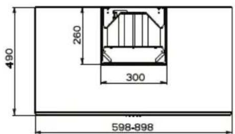
text_image
490 260 300 598-898Onderdelen
Ref. Productonderdelen
Ref. Installatieonderdelen
natural_image
Diagram showing a mechanical component with an inset view of a tool interacting with a green arrow (no text or symbols present)text_image
L T1 T2 T3 T4 ① 2 3 4/IBedieningspaneel
TOETS LED FUNCTIONS
text_image
V1 V2 V3S Lnatural_image
Illustration of a hand interacting with a device, showing a green arrow indicating direction (no text or symbols present)Geurfilter (filterversie)
VERVANGING FILTER MET ACTIEVE KOOLSTOF
natural_image
Illustration of a hand pressing down on a mechanical component with a green arrow indicating downward motion (no text or symbols)Verlichting
VERVANGING VAN DE LAMPEN
natural_image
Line drawing of a hand holding a mechanical component, no text or symbols presentRÅD OG ANVISNINGER
INSTALLATION
natural_image
Illustration of a greenhouse with a pot and smokestack emitting green smoke, crossed by a green ribbon (no text or symbols)Dimensioner

natural_image
Technical line drawing of a T-shaped structure with a base and top, showing dimension 60 (no text or symbols)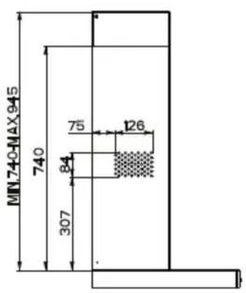
text_image
MIN 740-MAX 945 740 75 126 84 307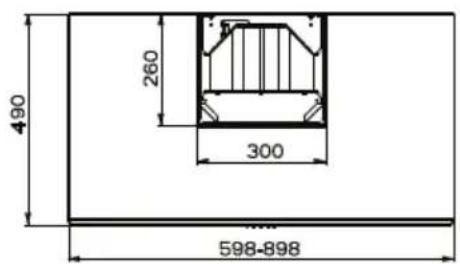
text_image
490 260 300 598-898Komponenter
AFSKÆRMET UDGAVE LUFTAFTRÆKSYSTEM
RECIRKULATIONS VERSION LUFTAFTRÆK
natural_image
Diagram showing a mechanical component with an inset view of a tool interacting with a green arrow (no text or symbols present)Montering af aftræk
text_image
L T1 T2 T3 T4 ① 2 3 4/IBetjeningspanel
KNAP LED FUNKTIONER
text_image
V1 V2 V3S Lnatural_image
Illustration of a hand pressing a green directional arrow on a device screen (no text or symbols)Aktivt kulfilter (recirkulationsudgave)
UDSKIFTNING AF DET AKTIVE KULFILTER
natural_image
Illustration of a hand pressing a component on a green surface, with a green arrow indicating direction (no text or symbols)Lys
UDSKIFTNING AF LYS
40 W glødelys.
natural_image
Line drawing of a hand holding a mechanical component, no text or symbols presentThe symbol 📄 on the product or on its packaging indicates that this product may not be treated as household waste. Instead it shall be handed over to the applicable collection point for the recycling of electrical and electronic equipment. By ensuring this product is disposed of correctly, you will help prevent potential negative consequences for the environment and human health, which could otherwise be caused by inappropriate waste handling of this product. For more detailed information about recycling of this product, please contact your local city office, your household waste disposal service or the shop where you purchased the product.