CS 200 - Treadmills Christopeit - Free user manual and instructions
Find the device manual for free CS 200 Christopeit in PDF.

User questions about CS 200 Christopeit
0 question about this device. Answer the ones you know or ask your own.
Ask a new question about this device
Download the instructions for your Treadmills in PDF format for free! Find your manual CS 200 - Christopeit and take your electronic device back in hand. On this page are published all the documents necessary for the use of your device. CS 200 by Christopeit.
USER MANUAL CS 200 Christopeit
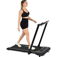
natural_image
Woman jogging on a treadmill with a running machine, no visible text or symbolsD
Assembly and exercise instructions for Order No. 1820
F
text_image
Technical diagram of a mechanical assembly with numbered components for identification and assembly reference.natural_image
Technical line drawing of a treadmill with adjustable arms and wheels (no text or symbols)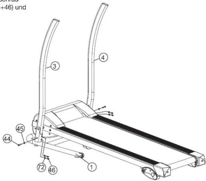
text_image
46 und +46 1 2 3 4 45 44 72 46Schritt 2:
text_image
Technical diagram of a treadmill with numbered parts for identification and assembly reference.Schritt 3:
text_image
Technical diagram of a treadmill with labeled parts and exploded view, showing front, side, and top views with numbered annotations.Schritt 4:
text_image
Technical diagram of a treadmill with numbered parts for identification and assembly reference.natural_image
Line drawing of a treadmill with a curved handle and wheels, showing motion direction (no text or symbols)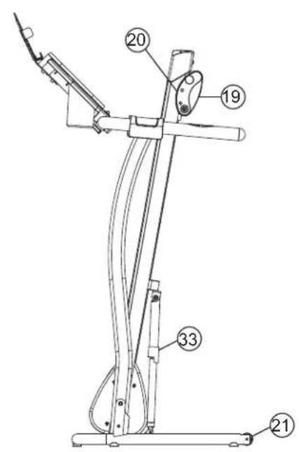
text_image
20 19 33 21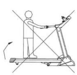
natural_image
Line drawing of a person using a treadmill with directional arrows indicating motion (no text or symbols)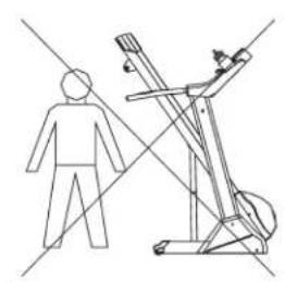
natural_image
Line drawing of a person standing next to a stationary exercise machine with motion lines (no text or symbols)
natural_image
Line drawing of a person using a stationary exercise machine (no text or symbols)
natural_image
Line drawing of a stationary exercise machine with no text or symbolsGarantiebestimmungen
km/h- Display (Speed):
Zeit-Display (Time):
Kalorien-Display (Calories):
natural_image
Simple line drawing of a person in a kneeling or stretching pose (no text or symbols)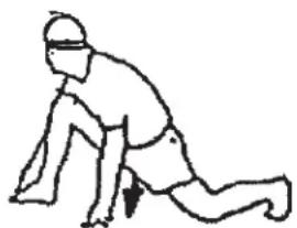
natural_image
Line drawing of a person in a kneeling position with a headband (no text or symbols)- Summary of Parts Page 3
- Important Recommendations and Safety Information Page 13
- Technical data Page 14 - 15
- Assembly Instructions With Exploded Diagrams Page 16 - 19
- Console Key pad functions Page 19 - 21
- Training Instructions, Warm up exercises (Warm Up) Page 22
Dear customer,
We congratulate you on your purchase of this home training sports unit and hope that we will have a great deal of pleasure with it. Please take heed of the enclosed notes and instructions and follow them closely concerning assembly and use.
Please do not hesitate to contact us at any time if you should have any questions.
Important Recommendations and Safety Instructions
Our products are all tested and therefore represent the highest current safety standards. However, this fact does not make it unnecessary to observe the following principles strictly.
- Assembly the machine exactly as described in the installation instructions and use only the enclosed, specific parts of the machine contained in the assembly. Before assembling, verify the completeness of the delivery against the delivery notice and the completeness of the carton against the parts list in the installation and operating instructions.
- Check the firm seating off all screws, nuts and other connections before using the machine for the first time and at regular intervals (every 1-2 months) to ensure that the trainer is in a safe condition. Replace defective components immediately and/or keep the equipment put of the use until repair.
- Set up the machine in a dry, level place and protect it from moisture and water. Uneven parts of the floor must be compensated by suitable measures and by the provided adjustable parts of the machine if such are installed. Ensure that no contact occurs with moisture or water.
- Place a suitable base (e.g. rubber mat, wooden board etc.) beneath the machine if the area of the machine must be specially protected against indentations, dirt etc.
- Before beginning training, remove all objects within a radius of 2 metres from the machine.
- Do not use aggressive cleaning agents to clean the machine and employ only the supplied tools or suitable tools of your own to assemble the machine and for any necessary repairs. Remove drops of sweat from the machine immediately after finishing training.
- WARNING! Systems of the heart frequency supervision can be inexact. Excessive training can lead to serious health damage or to the death. Consult a doctor before beginning a planned training programme. He can define the maximum exertion (pulse, Watts, duration of training etc.) to which you may expose yourself and can give you precise information on the correct posture during training, the targets of your training and your diet. Never train after eating large meals.
- Only train on the machine when it is in correct working order. Use original spare parts only for any necessary repairs. WARNING: Replace the worm parts immediately and keep this equipment out of use until repaired.
- When setting the adjustable parts, observe the correct position and the marked, maximum setting positions and ensure that the newly adjusted position is correctly secured. Please remove the Tools you need to adjust after adjusting a new position.
-
Unless otherwise described in the instructions, the machine must only be used for training by one person at a time. The exercise time should not overtake 45 min./daily.
-
Wear training clothes and shoes which are suitable for fitness training with the machine. Your clothes must be such that they cannot catch during training due to their shape (e.g. length). Your training shoes should be appropriate for the trainer, must support your feet firmly and must have non-slip soles.
- WARNING! If you notice a feeling of dizziness, sickness, chest pain or other abnormal symptoms, stop training and consult a doctor.
- Never forget that sports machines are not toys. They must therefore only be used according to their purpose and by suitably informed and instructed persons.
- People such as children, invalids and handicapped persons should only use the machine in the presence of another person who can give aid and advice. Take suitable measures to ensure that children never use the machine without supervision.
- Ensure that the person conducting training and other people never move or hold any parts of their body into the vicinity of moving parts.
- At the end of its life span this product is not allowed to dispose over the normal household waste, but it must be given to an assembly point for the recycling of electric and electronic components. You may find the symbol on the product, on the instructions or on the packing. The materials are reusable in accordance with their marking. With the re-use, the material utilization or the protection of our environment. Please ask the local administration for the responsible disposal place.
- To protect the environment, do not dispose of the packaging materials, used batteries or parts of the machine as household waste. Put these in the appropriate collection bins or bring them to a suitable collection point.
- The maximum permissible load (=body weight) is specified as 100 kg. Evaluate your body weight before you starting the exercise.
- If the connecting cable of this item is damaged, this must be replaced by the manufacturer or the customer service or with an electrically certified person.
- The assembly and operating instructions is part of the product. If selling or passing to another person the documentation must be provided with the product.
Part-List + Spare-Part List CS 200 Order No. 1820
Technical data: Issue: 01. 09. 2018
- 0,5 HP Motor continuous (0,37Kw), maximum 1,0 HP Motor Peak (0,74Kw)
• Speed from 1 km/h - 8 km/h (adjustable in 0,1 km/h steps)
• 3 individual program with target of Time, Distance and Calories
• 16 installed programs with different speed - Quick speed buttons for 3 km/h und 6 km/h
• 3 adjustable manual incline
• Hand pulse measurement
• Vibration absorbing running surface (Cushion System)
• Safety pin for emergency stop - Foldable for save space
- Blue Back Light LCD Display showing: Time, Speed, Distance, approx.. Calories consumption and pulse
- Inputs of limits at individual programs: Time, Speed and approx. Calories
- Fold-out automatic (Soft-Drop-System) for a safety and easy let down of the treadmill
- Transport rollers for an easy and comfortable move to location
- Walking surface approx. L 100 x W 34 cm
• Electrical data: 220-240V/50-60Hz /370 Watt - Load max. 100 kg (Body weight)
• Weight approx. 29,5kg
Space requirement approx: L 127 x W 63 x H 137 cm
Space requirement foldable approx: L 78 x W 63 x H 137 cm
Exercise space: approx. 6m²
Please check after opening the packing that all the parts shown in the following assembly steps are there. Once you are sure that this is the case, you can start assembly.
Please contact us if any components are defective or missing, or if you need any spare parts or replacements in future:
Internet service- and spare parts data base: www.christopeit-service.de
This treadmill is created only for private Home sports activity and not allowed to us in a commercial or professional area. Home Sport use class H/C

text_image
0 5 10 15 20 25 30 35 40 45 50 55 60 65 70 75 80 85 90 95 100 mm| No. | Designation | Dimension mm | Quantity | Attached to Illustration No. | ET-Number | |
| 1 | Base frame | 1 | 2 | 33-1820-01-SW | ||
| 2 | Main frame | 1 | 1 | 33-1820-02-SI | ||
| 3 | Handrail support left | 1 | 1 | 33-1820-03-SW | ||
| 4 | Handrail support right | 1 | 1 | 33-1820-04-SW | ||
| 5 | Handrail | 1 | 3+4 | 33-1820-05-SW | ||
| 6 | Tablet holder bracket | 1 | 32 | 33-1820-06-SW | ||
| 7 | Reinforced tube | 3 | 2+8 | 33-1820-07-SI | ||
| 8 | Running deck | 892x442 | 1 | 2 | 36-1820-04-BT | |
| 9 | Front roller | 1 | 2+11 | 33-1820-08-SI | ||
| 10 | Rear roller | 1 | 2+11 | 33-1820-09-SI | ||
| 11 | Running belt | 2115x360 | 1 | 9+10 | 36-1820-05-BT | |
| 12 | Upper motor cover | 1 | 2 | 36-1820-01-BT | ||
| 13 | Side rail | 895x75 | 2 | 2 | 36-1820-06-BT | |
| 14 | Left end cover | 1 | 2 | 36-1820-07-BT | ||
| 15 | Right end cover | 1 | 2 | 36-1820-08-BT | ||
| 16 | Lower motor cover | 1 | 2 | 36-1820-24-BT | ||
| 17 | Belt | 4P/140J | 1 | 9+18 | 36-1820-10-BT | |
| 18 | Motor | 1 | 2 | 33-1820-10-SI | ||
| 19 | Incline adjuster | 2 | 2 | 36-1820-11-BT | ||
| 20 | Lock pin | 2 | 2+19 | 36-1820-12-BT | ||
| 21 | Transport wheel | 2 | 1 | 36-1820-13-BT | ||
| 22 | Foot pad | 5 | 1 | 36-1820-14-BT | ||
| 23 | Rectangular end cap | 40x25 | 2 | 2 | 36-1241-15-BT | |
| 24 | Power switch | 1 | 2+41 | 36-1352-29-BT | ||
| 25 | Handlebar end cap | 32 | 2 | 5 | 36-1820-17-BT | |
| 26 | Handrail foam grip long | 30x260 | 2 | 5 | 36-1820-18-BT | |
| 27 | Pulse sensor | 2 | 5 | 36-1820-28-BT | ||
| 28 | Tablet holder | 1 | 32 | 36-1820-19-BT | ||
| 29 | Cup holder | 1 | 32 | 36-1820-20-BT | ||
| 30 | Safety key | 1 | 32 | 36-1820-21-BT | ||
| 31 | Handrail foam grip short | 30x230 | 2 | 5 | 36-1820-22-BT | |
| 32 | Computer | 1 | 5 | 36-1820-03-BT | ||
| 33 | Gas spring | 1 | 1+2 | 36-1820-29-BT | ||
| No. Designation Dimension mm Quantity Attached to Illu- | stration No. | ET-Number | ||||
| 34 Foot pad for motor 4 18 36-1820-23-BT | ||||||
| 35 Power control board 1 2 36-1820-09-BT | ||||||
| 36 Connection cable 1 35+37 36-1820-25-BT | ||||||
| 37 Computer connection cable 1 32+36 36-1820-26-BT | ||||||
| 38 AC power cable 1 35 36-1352-31-BT | ||||||
| 39 Power cable stop 1 38 36-1352-44-BT | ||||||
| 40 Handrail cover 2 5 36-1820-02-BT | ||||||
| 41 Overload fuse | 1 24+35 36-1352-30-BT | |||||
| 42 Cable protection | 3 2+4 | 36-1820-27-BT | ||||
| 43 Hexagon head bolt | M12x85 2 1,3+4 | 39-10316-SW | ||||
| 44 | Hex bolt | M8x40 | 4 | 1,3,4+21 | 39-10125-VC | |
| 45 | Washer | 8//16 | 8 | 44,47,53+59 | 39-9862-CR | |
| 46 Hex bolt | M8x16 | 4 1,3+4 | 39-9888 | |||
| 47 Hex bolt | M8x30 | 1 1+33 | 39-10134 | |||
| 48 Washer | 5//10 | 2 51 39-10111-SW | ||||
| 49 Cross head screw | 3x10 | 4 35 39-10078 | ||||
| 50 Nylon nut | M8 | 4 47-49 | 39-9818 | |||
| 51 Cross head screw | M5x20 | 2 14+15 39-10165 | ||||
| 52 Cross head screw | M6x25 | 1 9 39-10029 | ||||
| 53 Hex bolt | M8x55 | 3 2,9+10 | 39-10056 | |||
| 54 | Cross head counter sunk bolt | M6x25 | 4 | 2+8 | 39-9959 | |
| 55 | Cross head bolt | M6x35 | 6 | 2+8 | 39-9979-VC | |
| 56 | Cross head screw | M6x16 | 4 | 6+32 | 39-10120-VC | |
| 57 Nut | M6 | 10 | 54+55 39-9891-CR | |||
| 58 Nut | M8 | 4 59 39-9818 | ||||
| 59 Hex bolt | M8x25 | 4 2+18 | 39-10455 | |||
| 60 Magnetic ring | 1 18 36-1820-15-BT | |||||
| 61 Washer | 13//26 | 2 43 39-10062 | ||||
| 62 | Cross head screw | M5x10 | 8 | 2+16 | 39-9903 | |
| 63 Bumper pad | 4 2+8 | 36-1820-30-BT | ||||
| 64 Cross head bolt | M4x10 | 1 2 36-9210-30-BT | ||||
| 65 Spring washer | for M4 | 1 64 39-10058 | ||||
| 66 | Cross head screw | 4x20 | 2 | 5+27 | 36-9210-31-BT | |
| 67 Hex bolt | M8x50 | 7 2-5,19+33 39-9811 | ||||
| 68 Spring washer | for M8 | 4 59 39-9864-VC | ||||
| 69-71 | - | - | ||||
| 72 Curved washer | 8//19 | 8 67 39-9966-CR | ||||
| 74 | Handgrip screw | M6 | 1 | 5+32 | 36-1820-16-BT | |
| 75 Allen key wrench | 5mm | 1 | 36-9119-34-BT | |||
| 76 Allen key wrench | 6mm | 1 | 36-9116-14-BT | |||
| 78 Multi wrench | 1 | 36-9107-27-BT | ||||
| 79 Assembly and exercise instructions | 1 | 36-1820-31-BT | ||||
Assembly Instructions
Put everything clearly on the ground and control the completeness based on the assembly steps. Attention: The simplified assembly process requires 100% attention. Especially in the crease and folding positions. Assembly time is approx. 20min.
Step 1:
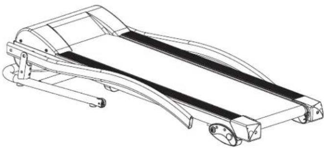
- Remove all small parts, loose packing material out of the box and then take out with help of a second person the preassembled frame of packaging.
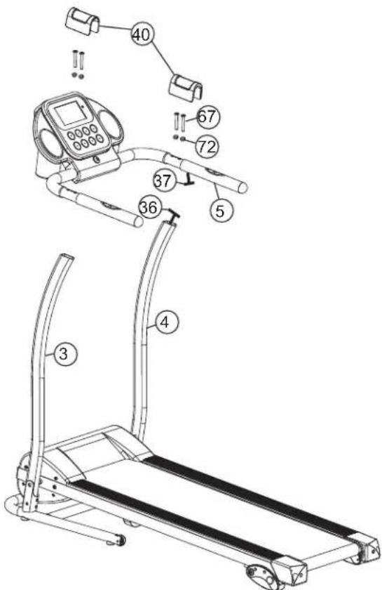
- Place the screws M8x16 (44), screws M8x40 (46) and washers (45+72) on left and right side of base frame (1).
- Fold up with care the supports left and right (3+4) and tighten the supports left and right (3+4) with screws (44+46) and washers (54+72) at base frame (1).
natural_image
Technical line drawing of a treadmill with adjustable arms and wheels (no text or symbols)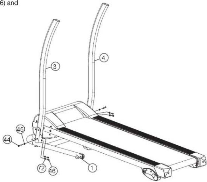
text_image
(6) and 1 2 3 4 45 44 72 46Step 2:
- Place the handrail (5) to the supports (3+4) and connect on right side the connection cable (36) with computer cable (37).
- Put the hand rail (5) onto the supports (3+4) that screw holes are aligned and screw it tightly by using screws M8x50 (67) and washers (72). Ensure that the cable connections made are not squashed.
- Attach the handrail covers (40) onto the handrail (5) connection points.
text_image
Technical diagram of a treadmill with numbered parts and labeled componentsStep 3:
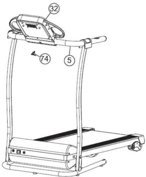
- Secure the computer (32) at handrail (5) into desired incline position with handgrip screw (74).
- Attach the tablet holder (28) at Computer (32) by using screws M6x16 (56).
- Put the cup holder (29) into the intended position at computer (32).
text_image
32 74 5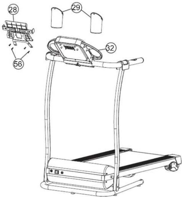
text_image
Technical diagram of a treadmill with numbered parts and exploded view, showing front, side, and top views.Step 4:
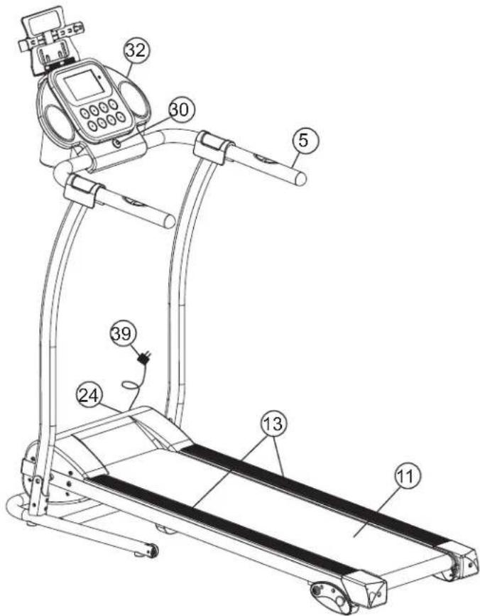
Checks and How to start
- Check the correct installation and function of all screwed and plug connections.
- When everything is in order, connect the power supply cable (39) with wall power (220-240V\~50-60Hz) and switch on the main switch (24) below the front frame.
- Put the safety key (30) onto the computer (32) and the computer will show normal manual mode. Put the safety clip (30) at your exercising cloth and stand on the side rails (13). Press Start-Button and after a Count Down the treadmill start moving. Start walking onto the walk surface (11) when speed is slowly and follow the speed. Familiarize yourself with the machine at a low speed settings.
- Run in the middle of the running surface (11), hold yourself tight at handrail (5) if you feel insecure and don't step on the side foot rails (13). Only run with look at the Computer (32) on the treadmill during the running. In emergency case, step of the treadmill lateral and hold on to the handle (5).
Note:
Please keep the tool set and the instructions in a safe place as these may be required for repairs or spare parts orders becoming necessary later.
text_image
Technical diagram of a treadmill with numbered parts for identificationIncline adjustment:
Raise the basic frame with a hand and fold the treadmill together until it is arrested. Pull out both security pins (20), shift the incline adjuster (19) in another position and you use the security pins (20) again. The treadmill can folded down. The incline adjustment is intended in addition to raise the load of the mountain accrual.
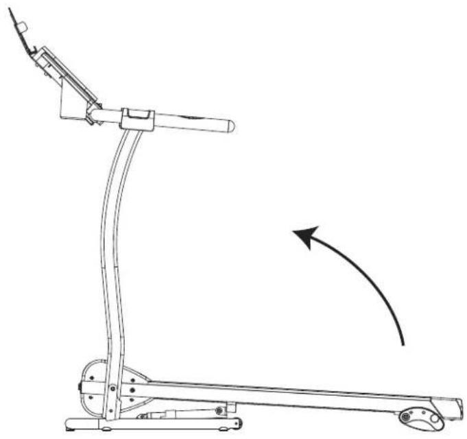
How to move/store your treadmill:
- Put one hand at the end caps of the running frame and lift up into vertically position that it automatically locks the upright position.
- Place your hands on top of the handrails, than lean the machine toward your body until it is easy moveable on transportation rollers (21).
Warning:
Before folding up the treadmill switch off and wait until the running surface totally stopped.
Don't start the treadmill in fold up position!
natural_image
Line drawing of a treadmill with an arrow indicating rotational motion (no text or symbols)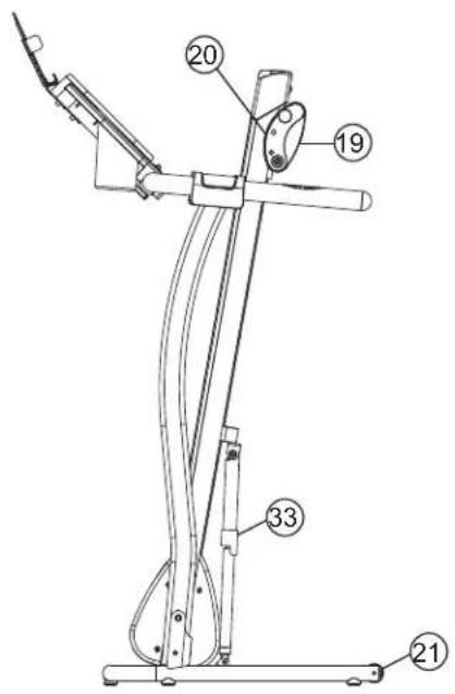
text_image
20 19 33 21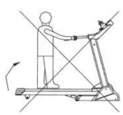
natural_image
Line drawing of a person using a treadmill with directional arrows indicating motion (no text or symbols)
natural_image
Line drawing of a person standing next to a stationary exercise machine (no text or symbols)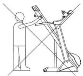
natural_image
Line drawing of a person using a stationary exercise machine (no text or symbols)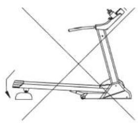
natural_image
Line drawing of a stationary exercise machine with no text or symbolsMaintenance and adjusting
1. Lubrication for the running belt:
In order to keep the machine in the best condition, please add some Silicone oil between the running belt and the running board after 50 hours or 1 to 2 month of use. But the running belt may slip, if you lubricate too much. To lubricate the belt please pull the walking belt up and injection the silicone oil into the gap between belt and walking deck.
2. Adjusting running belt:
You need to adjust the walking belt to the normal position, per the following steps if it is off.
- Set speed at 3-5km.
- Using the Allen key to adjust the belt tension bolt on the end cap of the system frame.
- If you want to move the belt towards left, turn the right tension bolt clockwise.
- If you want to move the belt towards right, turn the left tension bolt clockwise.
- If you have already done according to the steps above and it is still not at the good range, then the running belt should be damaged already, please contact your local dealer for replacement.
Note: Make sure that the running surface is as centered as possible. Once these moves too far from the center, (about 10 mm) it should be readjusted into the center.
3. Running belt slips:
- Make sure the walking belt is not too loose.
- Make sure the motor belt is not too loose.
4. No light on the Display:
- Check if the power plug is properly connected.
- Check if the safety key on the computer is in place.
- Check if the wire in the right post is properly connected.
Remind! Before you inspect any wire or electrician part, please ensure that the Power supply has been turned off.
5. Abnormal noise from the machine
- Check if any screw of machine is loose.
- Check if the motor belt is off.
- Check if the running belt is off.
Note:
Please contact your local dealer if you have checked all the above listed things but the problem is still there.

natural_image
Technical line drawing of a mechanical component with hands adjusting parts (no text or symbols)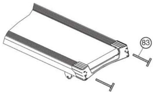
natural_image
Technical line drawing of a mechanical component with fasteners and a numbered annotation (83), no readable text or symbols present.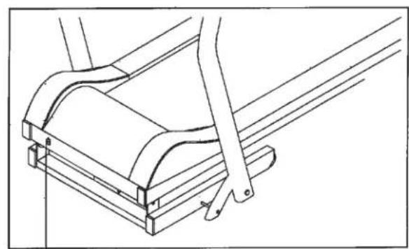
natural_image
Technical line drawing of a mechanical assembly with no visible text or symbols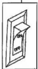
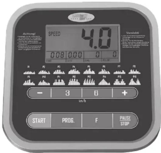
USER MANUAL OF COMPUTER
text_image
Achungsi SPEED 4.0 008 000 0 0 TIME Q19 CAL PULM Vorsichts Start PROG. F PAUSE STOPFunction of Displays:
Pulse-Display:
Shows actually heart rate data.
Speed-Display:
Shows actually speed in km/h.
Distance-Display:
Shows actually distance in KM.
Time-Display:
Shows actually time of exercising in minutes and seconds.
Calories-Display:
Shows actually calories in kcal.
Program-No. Display:
Shows actually exercise programs P1\~P16.
Function of keys:
Prog-key:
PROGRAM key: On the stop status, press Prog-key to select exercising speed programs P1-P16
F-key:
Select key of time-, distance- or calories program.
Start-key:
Press Start-key to start exercise program (motor starts running).
Stop/Pause -Key:
Press Stop/Pause-key during exercise to interrupt the program (motor stops running). Within 5 min. you can press Start-Key to continue this exercise program or press Stop/Pause -key again to finish this program. Pre-values can set to zero by pressing the Stop/Pause-key.
“+”-key:
Press speed up key increase settings or motor speed.
“-”-key:
Press speed down key decrease settings or motor speed.
Quick Speed- keys 3 + 6km/h:
Press one of these keys and the speed changes direct into 3 and 6km/h.
MANUAL MODE:
How to start manual mode:
Put in the AC plug in wall power 230V\~50Hz and put on the power switch (24). Put safety clip (30) onto the computer and it will show normal manual mode. Stand your feet on both side rails. Put the safety key at you exercise cloth and press start-key to start with exercising. After a 5 sec. count down, the motor begin to run slowly and you can step on the running belt and follow the speed. Adjust the speed with "+" and "-" -keys into desired speed. If put off the safety clip from computer at any time, the motor stop slowly and the display will show „---“. After put on the safety key on computer the normal manually program will show. Press "+" or "-" -key to adjust value of speed. Press quick speed -key to adjust speed quickly. All values of the displays will counter up.
Setting Programs Time-Distance-Calories:
Time Program:
On the normal manual mode, press F-key, to enter time program. The time display will flash and the initial value is 30:00. Press "+" -key or "-" -key to set value. The range is: 5:00-99:00. If set a value the display counts up till zero and then stops running motor.
Distance-Program:
On the normal manual mode, press F-key, to enter distance program. The distance display will flash and the initial value is 1,00KM. Press "+" -key or "-" -key to set value. The range is: 0,5-65:0 KM. If set a value the display counts up till zero and then stops running motor.
Calories-Program:
On the normal manual mode, press F-key, to enter calories program. The calories display will flash and the initial value is 50kcal. Press "+" -key or "-" -key to set value. The range is: 10-995kcal. If set a value the display counts up till zero and then stops running motor.
RANGE OF ALL FUNCTIONS:
| INITIAL INITIAL SETTING VALUE RANGE | RANGE | DISPLAY | ||
| TIME(MIN:SEC) 0:00 | 30:00 | 5:00 | -99:00 0:00 | -99:59 |
| SPEED(KM/H) | 0.0 | N/A | N/A | 1.0-8.0 |
| DISTANCE(KM) | 0.00 | 1.00 | 0.5-65.0 | 0.00-99.99 |
| PULSE(BPM) | P | N/A | N/A | 50-200 |
| CALORIES(KCAL) | 0 | 50 | 10-995 | 0-999 |
Exercise programs P1-P16:
On the normal manual mode, press Prog-key to chose one of the exercise speed programs P1-P16. Each program is divided into 20 intervals of time and the speed changes as following program list shows. Initial setting time is 30min, set a time for training session and press Start to start the program. Pressing Stop to have a break or finish earlier the program. Press speed "+" or "-" - key to adjust speed during the program if it is to quick or slow. With next intervals of time the speed level will change back to program mode. If the program runs till end of time the motor will stop running after the display counts down time to zero.
Programs in 20 intervals of time
| Programm | 1 | 2 | 3 | 4 | 5 | 6 | 7 | 8 | 9 | 10 | 11 | 12 | 13 | 14 | 15 | 16 | 17 | 18 | 19 | 20 | |
| P1 Km/h 2 | 3 3 4 5 | 3 4 | 5 5 | 3 4 | 5 4 | 4 4 | 2 3 | 3 5 | 3 | ||||||||||||
| P2 | Km/h | 2 | 4 | 4 | 5 | 6 | 4 | 6 | 6 | 6 | 4 | 5 | 6 | 4 | 4 | 4 | 2 | 2 | 5 | 4 | 2 |
| P3 | Km/h | 2 | 4 | 4 | 6 | 6 | 4 | 7 | 7 | 7 | 4 | 7 | 7 | 4 | 4 | 4 | 2 | 4 | 5 | 3 | 2 |
| P4 | Km/h | 3 | 5 | 5 | 6 | 7 | 7 | 5 | 7 | 7 | 8 | 8 | 5 | 8 | 5 | 5 | 6 | 6 | 4 | 4 | 3 |
| P5 | Km/h | 2 | 4 | 4 | 5 | 6 | 7 | 7 | 5 | 6 | 7 | 8 | 8 | 5 | 4 | 4 | 6 | 5 | 5 | 4 | 2 |
| P6 Km/h 2 | 4 3 4 5 | 4 8 | 7 5 | 7 8 | 3 6 | 4 4 | 2 5 | 4 3 | 2 | ||||||||||||
| P7 Km/h 2 | 3 3 3 4 | 5 3 | 4 5 | 3 4 | 5 3 | 3 3 | 6 6 | 5 3 | 3 | ||||||||||||
| P8 | Km/h | 2 | 3 | 3 | 6 | 7 | 7 | 4 | 6 | 7 | 4 | 4 | 4 | 6 | 7 | 4 | 4 | 4 | 2 | 3 | 2 |
| P9 Km/h 2 | 4 4 7 7 | 4 7 | 8 4 | 8 6 | 8 4 | 4 4 | 5 6 | 3 3 | 2 | ||||||||||||
| P10 | Km/h | 2 | 4 | 5 | 6 | 7 | 5 | 4 | 6 | 8 | 8 | 6 | 6 | 5 | 4 | 4 | 2 | 4 | 4 | 3 | 3 |
| P11 Km/h 3 | 4 5 8 | 5 8 | 5 5 | 5 8 | 8 5 5 | 5 6 | 8 8 | 7 6 | 3 | ||||||||||||
| P12 Km/h 2 | 5 8 8 | 7 7 | 8 8 | 7 7 | 8 8 6 | 6 8 | 8 5 | 5 4 | 3 | ||||||||||||
| P13 | Km/h | 3 | 6 | 8 | 8 | 3 | 6 | 8 | 8 | 3 | 6 | 8 | 8 | 3 | 6 | 8 | 8 | 3 | 6 | 8 | 3 |
| P14 | Km/h | 2 | 3 | 4 | 5 | 6 | 7 | 8 | 8 | 7 | 6 | 8 | 7 | 6 | 5 | 4 | 3 | 2 | 3 | 4 | 2 |
| P15 | Km/h | 3 | 3 | 6 | 6 | 8 | 8 | 7 | 7 | 6 | 6 | 3 | 3 | 6 | 6 | 8 | 8 | 6 | 6 | 3 | 3 |
| P16 | Km/h | 2 | 3 | 4 | 6 | 7 | 8 | 8 | 7 | 6 | 5 | 4 | 3 | 2 | 6 | 8 | 8 | 8 | 6 | 4 | 2 |
Function of safety key
The safety clip (30) has an emergency function. In fear or danger or if you fall down or jumped from it, the safety clip will lose position at computer and stops the motor with break system.
Put the safety key out from computer on any status, the display is „---“, the buzzer beep each second. Put the safety key on computer, then the display will enter normal manual mode. All parameter reset to zero.
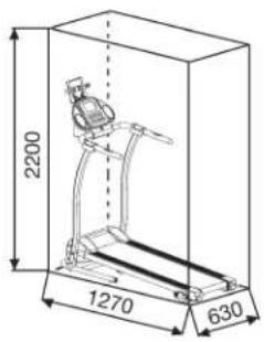
Training area in mm (for home trainer and user)
text_image
2200 1270 630Free area in mm
(Training area and security area
(rotating 60cm))
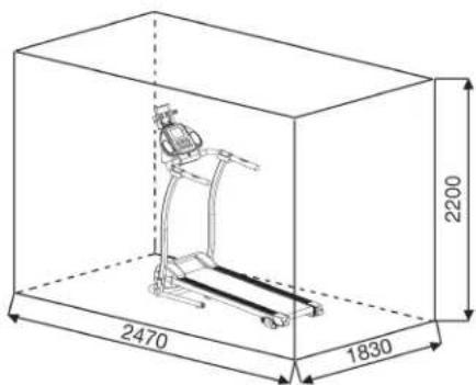
text_image
2470 1830 2200Training instructions
You must consider the following factors in determining the amount of training effort required in order to attain tangible physical and health benefits:
1. Intensity:
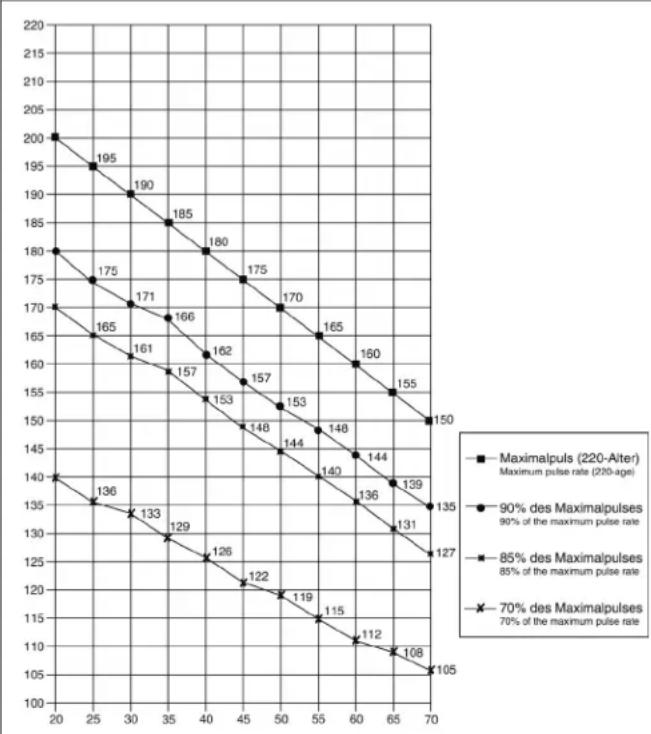
The level of physical exertion in training must exceed the level of normal exertion without reaching the point of breathlessness and / or exhaustion. A suitable guideline for effective training can be taken from the pulse rate. During training this should rise to the region of between 70% to 85% of the maximum pulse rate (see the table and formular for determination and calculation of this).
During the first weeks, the pulse rate should remain at the lower end of this region, at around 70% of the maximum pulse rate. In the course of the following weeks and months, the pulse rate should be slowly raised to the upper limit of 85% of the maximum pulse rate. The better the physical condition of the person doing the exercise, the more the level of training should be encreased to remain in the region of between 70% to 85% of the maximum pulse rate. This should be done by lengthening the time for the training and / or encreasing the level of difficulty.
If the pulse rate is not shown on the computer display or if for safety reasons you wish to check your pulse rate, which could have been displayed wrongly due to error in use, etc., you can do the following:
a. Pulse rate measurement in the conventional way (feeling the pulse at the wrist, for example, and counting the number of beats in one minute).
b. Pulse rate measurement with a suitable specialised device (available from dealers specialising in health-related equipment).
2.Frequency
Most experts recommend a combination of health-conscious nutrition, which must be determined on the basis of your training goal, and physical training three times a week. A normal adult must train twice a week to maintain his current level of condition. At least three training sessions a week are required to improve one's condition and reduce one's weight. Of course the ideal frequency of training is five sessions a week.
3. Planning the training
Each training session should consist of three phases: the warm-up phase, the training phase, and the cool-down phase. The body temperature and oxygen intake should be raised slowly in the warm-up phase. This can be done with gymnastic exercises lasting five to ten minutes.
Then the actual training (training phase) should begin. The training exertion should be relatively low for the first few minutes and then raised over a period of 15 to 30 minutes such that the pulse rate reaches the region of between 70% to 85% of the maximum pulse rate.
In order to support the circulation after the training phase and to prevent aching or strained muscles later, it is necessary to follow the training phase with a cool-down phase. This should be consist of stretching exercises and / or light gymnastic exercises for a period of five to ten minutes.
You find further information on the subject warm-up exercises, stretch exercises or general gymnastics exercises in our download area under www.christopeit-sport.com
4. Motivation
The key to a successful program is regular training. You should set a fixed time and place for each day of training and prepare yourself mentally for the training. Only train when you are in the mood for it and always have your goal in view. With continuous training you will be able to see how you are progressing day by day and are approaching your personal training goal bit by bit.
line
| X | Maximalpuls (220-Alter) Maximum pulse rate (220-age) | 90% des Maximalpulses 90% of the maximum pulse rate | 85% des Maximalpulses 85% of the maximum pulse rate | 70% des Maximalpulses 70% of the maximum pulse rate | |---|---|---|---|---| | 20 | 200 | 180 | 170 | 136 | | 25 | 195 | 175 | 165 | 133 | | 30 | 190 | 171 | 161 | 129 | | 35 | 185 | 166 | 157 | 126 | | 40 | 180 | 162 | 153 | 122 | | 45 | 175 | 157 | 148 | 119 | | 50 | 170 | 153 | 144 | 115 | | 55 | 165 | 148 | 140 | 112 | | 60 | 160 | 144 | 136 | 108 | | 65 | 155 | 139 | 131 | 105 | | 70 | 150 | 135 | 127 | - | The chart displays a single descending trend from top-left to bottom-right. The legend defines four distinct pulse rate thresholds: Maximalpuls (220-Alter), 90% des Maximalpulses, 85% des Maximalpulses, and 70% des Maximalpulses. The x-axis ranges from 20 to 70, and the y-axis ranges from 100 to 220. The data points are explicitly labeled on the chart.Calculation formula: Maximum pulse rate = 220 - age (220 minus your age)
90% of the maximum pulse rate = (220 - age) x 0.9
85% of the maximum pulse rate = (220 - age) x 0.85
70% of the maximum pulse rate = (220 - age) x 0.7
Warm up exercises (Warm Up)
Start your warm up by walking on the spot for at least 3 minutes and then perform the following gymnastic exercises to the body for the training phase to prepare accordingly. The exercises do not overdo it and only as far run until a slight drag felt. This position will hold a while.
natural_image
Simple line drawing of a person in a kneeling position with an arrow indicating motion (no text or symbols)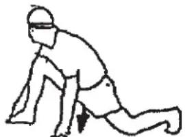
natural_image
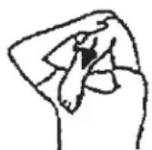
Line drawing of a person in a kneeling position with a downward arrow indicating motion (no text or symbols)Reach with your left hand behind your head to the right shoulder and pull with the right hand slightly to the left elbow. After 20sec. switch arm.
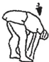
Bend forward as far forward as possible and let your legs almost stretched. Show it with your fingers in the direction of toe. 2 x 20sec.
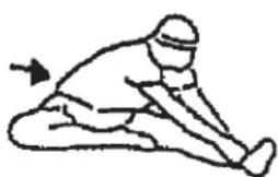
Sit down with one leg stretched out on the floor and bend forward and try to reach the foot with your hands. 2 x 20sec.
Kneel in a wide lunge forward and support yourself with your hands on the floor. Press the pelvis down. Change after 20 sec leg.
After the warm-up exercises by some arms and legs shake loose.
Don't finish the exercise phase abruptly, but will cycle leisurely something without resistance from to return to the normal pulse-zone. (Cool down) We recommend the warm-up exercises at the end of the training be conducted and to end your workout with shaking of the extremities.
F
Sommaire
Dimensions approximatives : L 127 x I 63 x H 137 cm
Dimensions approximatives en position repliée: L 78 x I 63 x H 137 cm
natural_image
Technical line drawing of a treadmill with adjustable arms and wheels (no text or symbols)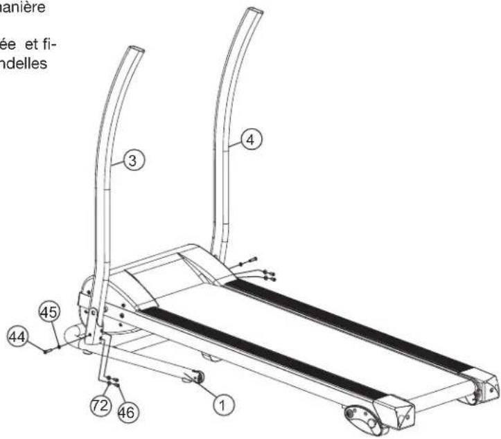
text_image
Technical diagram of a treadmill with numbered parts and labeled componentsÉtape n° 3:
text_image
Technical diagram of a treadmill with numbered parts labeled 32, 5, and 74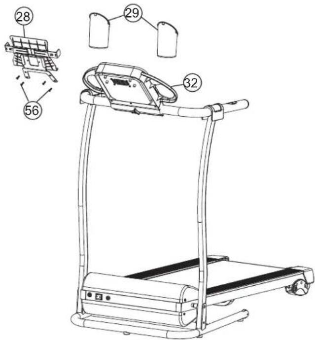
text_image
Technical diagram of a treadmill with numbered parts and exploded view, including labeled parts 28, 29, 32, and 56.Étape n° 4:
text_image
Technical diagram of a treadmill with numbered parts for identificationnatural_image
Line drawing of a treadmill with an arrow indicating rotational motion (no text or symbols)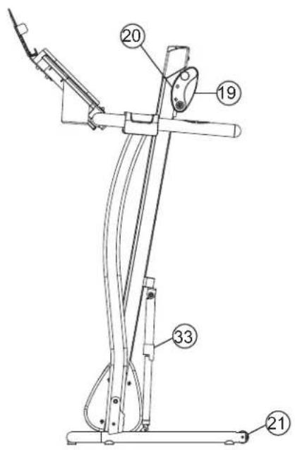
text_image
20 19 33 21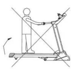
natural_image
Line drawing of a person using a treadmill with directional arrows indicating motion (no text or symbols)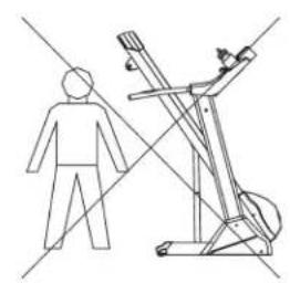
natural_image
Line drawing of a person standing next to a stationary exercise machine with a leg and arm (no text or symbols)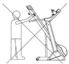
natural_image
Line drawing of a person using a stationary exercise machine (no text or symbols present)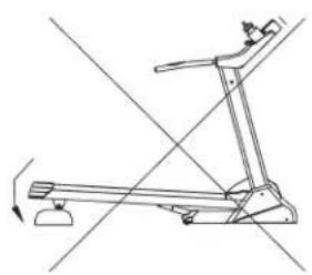
natural_image
Line drawing of a treadmill with motion lines indicating movement (no text or symbols)natural_image
Technical line drawing of a mechanical component with hands adjusting parts (no text or symbols)
natural_image
Technical line drawing of a mechanical component with mounting holes and a circular annotation labeled '83' (no text or symbols beyond the label)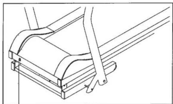
natural_image
Technical line drawing of a mechanical assembly with no visible text or symbols
Ecran Pulse (Pulsation):
natural_image
Simple line drawing of a person in a kneeling position with an arrow indicating motion (no text or symbols)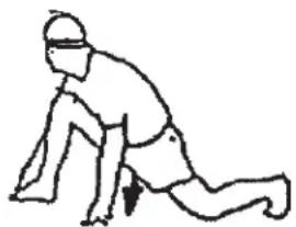
natural_image
Line drawing of a person in a kneeling or stretching pose (no text or symbols)The image contains a graphical representation of a ruler, but no textual content is present.
0 5 10 15 20 25 30 35 40 50 60 70 80 90 100 mm
| Afb. nr. | Beschrijving Afmetingen | mm | Aantal stuks | Gemonteerd aan afbeeldingsnr. | ET-nummer |
| 1 Vloerframe | 1 | 2 | 33-1820-01-SW | ||
| 2 Hoofoframe | 1 | 1 | 33-1820-02-SI | ||
| 3 Steunpijp links | 1 | 1 | 33-1820-03-SW | ||
| 4 Steunpijp rechts | 1 | 1 | 33-1820-04-SW | ||
| 5 Leuning | 1 | 3+4 | 33-1820-05-SW | ||
| 6 | Opslagplaats houder | 1 | 32 | 33-1820-06-SW | |
| 7 | Loopplaat ondersteuning | 3 | 2+8 | 33-1820-07-SI | |
| 8 | Loopplaat | 892x442 | 1 | 2 | 36-1820-04-BT |
| 9 Voorste rol | 1 | 2+11 | 33-1820-08-SI | ||
| 10 | Achterste rol | 1 | 2+11 | 33-1820-09-SI | |
| 11 | Loopoppervlak | 2115x360 | 1 | 9+10 | 36-1820-05-BT |
| 12 | Bekleding | 1 | 2 | 36-1820-01-BT | |
| 13 | Zeijdebar | 895x75 | 2 | 2 | 36-1820-06-BT |
| 14 | Afsluitkap links | 1 | 2 | 36-1820-07-BT | |
| 15 | Afsluitkap rechts | 1 | 2 | 36-1820-08-BT | |
| 16 | Lager bekleding | 1 | 2 | 36-1820-24-BT | |
| 17 | Flakke riem | 4P/140J | 1 | 9+18 | 36-1820-10-BT |
| 18 | Motor | 1 | 2 | 33-1820-10-SI | |
| 19 | Steigingsbeugel | 2 | 2 | 36-1820-11-BT | |
| 20 | Veiligheidspin | 2 | 2+19 | 36-1820-12-BT | |
| 21 | Transportrol | 2 | 1 | 36-1820-13-BT | |
| 22 | Rubberenvoet | 5 | 1 | 36-1820-14-BT | |
| 23 | Vierkante stop | 40x25 | 2 | 2 | 36-1241-15-BT |
| 24 | Schakelaar | 1 | 2+41 | 36-1352-29-BT | |
| 25 | Ronde dop | 32 | 2 | 5 | 36-1820-17-BT |
| 26 | Greepovertrek lang | 30x260 | 2 | 5 | 36-1820-18-BT |
| 27 | Polseenheid | 2 | 5 | 36-1820-28-BT | |
| 28 | Opslagplaats | 1 | 32 | 36-1820-19-BT | |
| 29 | Bekerhouder | 1 | 32 | 36-1820-20-BT | |
| 30 | Veiligheidsclip | 1 | 32 | 36-1820-21-BT | |
| 31 | Greepovertrek kort | 30x230 | 2 | 5 | 36-1820-22-BT |
| 32 | Computer | 1 | 5 | 36-1820-03-BT | |
| 33 | Gas demper | 1 | 1+2 | 36-1820-29-BT | |
| 34 Rubberenschijf 4 18 36-1820-23-BT | |||||
| 35 Regelaar 1 2 36-1820-09-BT | |||||
| 36 Verbindingskabel 1 35+37 36-1820-25-BT | |||||
| 37 Computerkabel 1 32+36 36-1820-26-BT | |||||
| 38 Electriciteitskabel 1 35 36-1352-31-BT | |||||
| 39 Kabelvaszet 1 38 36-1352-44-BT | |||||
| 40 Greepafdekking 2 5 36-1820-02-BT | |||||
| 41 Bescherming overbelasting 1 24+35 36-1352-30-BT | |||||
| 42 Kabel vaszet 3 2+4 36-1820-27-BT | |||||
| 43 | Zeskantschroef | M12x85 | 2 | 1,3+4 | 39-10316-SW |
| 44 | Zeskantschroef | M8x40 | 4 | 1,3,4+21 | 39-10125-VC |
| 45 | Onderlegplaatje | 8//16 | 8 | 44,47,53+59 | 39-9862-CR |
| 46 | Binnenzeskantschroef | M8x16 | 4 | 1,3+4 | 39-9888 |
| 47 | Binnenzeskantschroef | M8x30 | 1 | 1+33 | 39-10134 |
| 48 Onderlegplaatje | 5//10 | 2 51 | 39-10111-SW | ||
| 49 Kruiskopschroef | 3x10 | 4 35 | 39-10078 | ||
| 50 Zelfborgene moer | M8 | 4 47 | 49 | 39-9818 | |
| 51 Kruiskopschroef | M5x20 | 2 14 | 15 39-10165 | ||
| 52 Kruiskopschroef | M6x25 | 1 9 | 39-10029 | ||
| 53 | Zeskantschroef | M8x55 | 3 | 2,9+10 | 39-10056 |
| 54 Verzonkenschroef | M6x25 | 4 2+8 | 39-9959 | ||
| 55 Kruiskopschroef | M6x35 | 6 2+8 | 39-9979-VC | ||
| 56 | Kruiskopschroef | M6x16 | 4 | 6+32 | 39-10120-VC |
| 57 Moer | M6 | 10 | 54+55 | 39-9891-CR | |
| 58 Moer | M8 | 4 59 | 39-9818 | ||
| 59 Zeskantschroef | M8x25 | 4 2+18 | 39-10455 | ||
| 60 Onderdrukkingsring | 1 18 | 36-1820-15-BT | |||
| 61 Onderlegplaatje | 13//26 | 2 43 | 39-10062 | ||
| 62 Kruiskopschroef | M5x10 | 8 2+16 | 39-9903 | ||
| 63 Rubberendemper | 4 2+8 | 36-1820-30-BT | |||
| 64 Kruiskopschroef | M4x10 | 1 2 | 36-9210-30-BT | ||
| 65 Veerring | voor M4 | 1 64 | 39-10058 | ||
| 66 | Kruiskopschroef | 4x20 | 2 | 5+27 | 36-9210-31-BT |
| 67 | Zeskantschroef | M8x50 | 7 | 2-5,19+33 | 39-9811 |
| 68 Veerring | voor M8 | 4 59 | 39-9864-VC | ||
| 69-71 | --- | ||||
| 72 Onderlegplaatje gebogen | 8//19 | 8 67 | 39-9966-CR | ||
| 74 | Handgreep schroef | M6 | 1 | 5+32 | 36-1820-16-BT |
| 75 | Binnenzeskant-Werktuig | 5mm | 1 | 36-9119-34-BT | |
| 76 | Binnenzeskant-Werktuig | 6mm | 1 | 36-9116-14-BT | |
| 78 Multi-Werktuig | 1 | 36-9107-27-BT | |||
| 79 Montage-en bedieningshandleiding | 1 | 36-1820-31-BT | |||
Montagehandleiding
natural_image
Technical line drawing of a treadmill with adjustable arms and wheels (no text or symbols)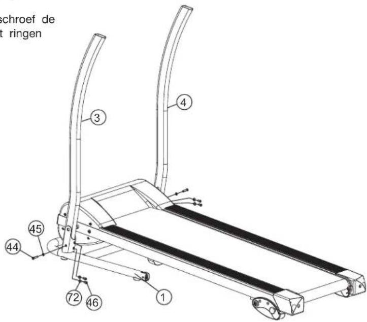
text_image
schroef de ringen 1 2 3 4 44 45 72 46Stap 2:
text_image
Technical diagram of a treadmill with numbered parts and labeled componentsStap 3:
text_image
Technical diagram of a treadmill with labeled parts and exploded view, showing front, side, and top views with numbered annotations.Stap 4:
text_image
Technical diagram of a treadmill with numbered parts for identificationPitch aanpassing:
natural_image
Line drawing of a treadmill with an arrow indicating rotational motion (no text or symbols)
text_image
20 19 33 21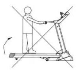
natural_image
Line drawing of a person using a treadmill with directional arrows indicating motion (no text or symbols)
natural_image
Line drawing of a person standing next to a treadmill with motion lines (no text or symbols)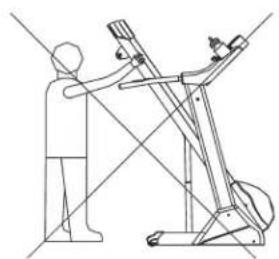
natural_image
Line drawing of a person using a stationary exercise machine (no text or symbols)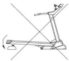
natural_image
Line drawing of a treadmill with motion lines indicating movement (no text or symbols)natural_image
Technical line drawing of a mechanical component with hands connecting it to a base plate (no text or symbols)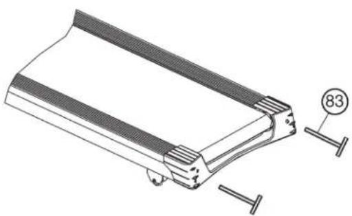
natural_image
Technical line drawing of a mechanical component with bolts and a circular annotation labeled '83' (no text or symbols beyond the label)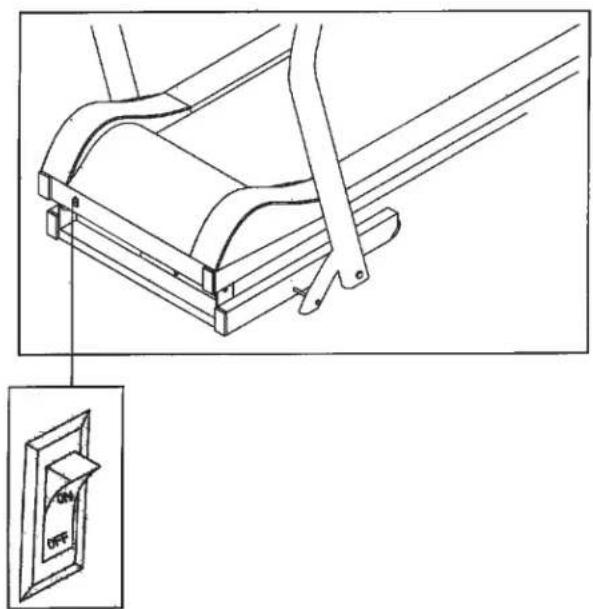
text_image
Technical diagram showing a mechanical assembly with an open switch labeled 'ON' and 'OFF' indicating status or operation.3. Planning van de training
natural_image
Simple line drawing of a person in a kneeling or stretching pose (no text or symbols)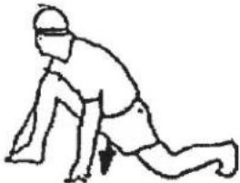
natural_image
Line drawing of a person in a kneeling or stretching pose (no text or symbols)text_image
top Sports© by Top-Sports Gilles GmbH
D-42551 Velbert (Germany)
Service: