
SDV2940 - TV Antenna PHILIPS - Free user manual and instructions
Find the device manual for free SDV2940 PHILIPS in PDF.
| Product Type | Indoor/Outdoor UHF/VHF TV Antenna |
| Brand | Philips |
| Model | SDV2940 |
| Power Supply | Power injector 120 V AC to 6 V DC (power supply included) |
| Connectivity | 6m RG-59 coaxial cable with F connectors |
| Amplification | Built-in amplifier with power injector |
| Installation | Indoor wall or outdoor mast (mount included) |
| Key Functions | UHF and VHF TV reception, signal amplification |
| Included Parts | Antenna, wall/mast mount, power injector, power supply, coaxial cable, weather boot, hardware |
| Warranty | 1-year limited (repair or replacement) |
| Technical Support | Email: accessorysupport@philips.com |
| Care and Cleaning | Clean with a dry, soft cloth. Do not use liquid or abrasive products. |
| Safety Instructions | Grounding mandatory for outdoor installation. Avoid power lines. |
| Operating Temperature | Indoor/outdoor use (weather protection via weather boot) |
Frequently Asked Questions - SDV2940 PHILIPS
User questions about SDV2940 PHILIPS
0 question about this device. Answer the ones you know or ask your own.
Ask a new question about this device
Download the instructions for your TV Antenna in PDF format for free! Find your manual SDV2940 - PHILIPS and take your electronic device back in hand. On this page are published all the documents necessary for the use of your device. SDV2940 by PHILIPS.
USER MANUAL SDV2940 PHILIPS
natural_image
Exterior view of a Philips HDTV antenna mounted on a pole, showing wiring and components (no readable text beyond branding)SDV2940/27
| EN | User manual | 3 |
| ES | Manual de utilizador | 9 |
| FR | Manuel d’utilisation | 16 |
PHILIPS
EN
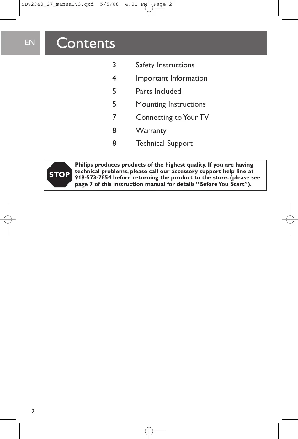
Contents
3 Safety Instructions
4 Important Information
5 Parts Included
5 Mounting Instructions
7 Connecting to Your TV
8 Warranty
8 Technical Support

Philips produces products of the highest quality. If you are having technical problems, please call our accessory support help line at 919-573-7854 before returning the product to the store. (please see page 7 of this instruction manual for details “Before You Start”).
Safety Instructions
EN
Philips SDV2940
Indoor/Outdoor UHF/VHF Television antenna
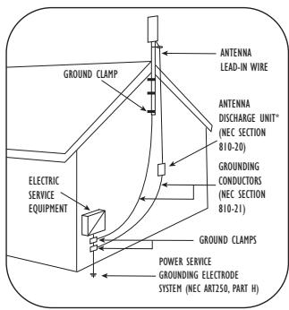
Example of Antenna Grounding as per NEC – National Electrical Code
* Antenna Discharge Unit is not required if lead in conductors are enclosed in a continuous metallic shield that is permanently and effectively grounded.
Antenna grounding
If an outside antenna is connected to the receiver, make sure the antenna system is grounded so as to provide protection against voltage surges and built up of static charges. Section 810 of the National Electrical Code, ANSI/NFPA No. 70-1984, provides information with respect to proper grounding of the mast and supporting structure, grounding of the lead-in wire to an antenna discharge unit, size of grounding connectors, location of antenna discharge-unit, connection to grounding electrodes, and requirements for the grounding electrode. See DIAGRAM TO LEFT.
Important Safety Notes
If you do not feel comfortable or competent to install this antenna we recommend that you seek the assistance of a qualified professional antenna installer.
Read the instructions for this device thoroughly before attempting installation.
The installation or dismantling of any antenna near power lines is dangerous. Each year hundreds of people are killed or injured while attempting to install or service antennas. For your safety and proper antenna installation, read and follow all safety precautions.
IMPORTANT READ BEFORE INSTALLATION
Outdoor antennas and lead-in conductors from antenna to a building should not cross over open conductors of electric light or power circuits. They should be kept away from all circuits to avoid the possibility of accidental contact.
Each conductor of a lead-in from an outdoor antenna should be connected with an antenna discharge unit. Antenna discharge units (or Lightning Arrestors) should be located outside the building between the point of entrance or the lead-in and the TV, and as near as practical to the entrance of conductors to the building.
Choose an installation site for safety as well as performance. All electric power lines, cable lines and telephone lines look alike. To be safe, assume ANY overhead line can kill you.
Do not place an antenna where it could potentially fall on to, or blow into a power line. If in doubt call your electric provider. Let them review your site.
Outdoor antennas should be grounded with an approved lighting arresting device. Local codes may apply. Use 8 AWG or larger ground wire.
EN
Safety Instructions
Height or other restrictions on antennas may apply to your installation depending on your proximity to an airport, or local ordinances.
Take the time to plan your installation procedure. Do all assembly work on the antenna on the ground. Raise the completed antenna after assembly.
Do NOT work on a wet, snowy or windy day or if a thunderstorm is approaching. Do NOT use a metal ladder.
IMPORTANT READ BEFORE INSTALLATION
If the antenna assembly starts to fall, get away from it and let it fall. Remember that the antenna mast and cable are all excellent conductors of electrical current.
Do NOT install the antenna by yourself. Be sure that there are two other people available for help.
If any part of the antenna should come in contact with a power line ... DON'T TOUCH IT OR TRY TO REMOVE IT YOURSELF. Call your local power company immediately. They will remove it.
Should an electrical accident occur . . . DON'T TOUCH THE PERSON IN CONTACT WITH THE POWER LINE, or you too can become electrocuted. Instead, use a DRY board, stick, or rope to push or pull the victim away from the power lines and antenna. Once clear, check the victim. If he has stopped breathing, immediately administer cardiopulmonary resuscitation (CPR) and stay with him. Have someone else call for medical help.
Install wire antennas high enough that they will not be "walked into" by people.
Do not install antenna wire(s) over or under utility lines.
Important Information
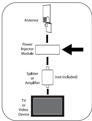
flowchart
graph TD
    A["Antenna"] --> B["Power Injector Module"]
    B --> C["Splitter or Amplifier (not included)"]
    C --> D["TV or Video Device"]
Important installation information
The SDV2940 uses a power injection module to power the antenna amplifier.
It is essential for proper operation of this antenna system that the amplifier be connected between the antenna and any devices such as splitters, matching transformers, networks, etc. SEE DIAGRAM TO LEFT.
Disregarding this important notice may result in damaging the power injector or improper operation / poor performance.
Parts Included
EN
- SDV2940 Antenna.... 1
- Power supply 120V to 6VDC ..... 1
- Wall / Mast Bracket.....1
- Nuts 2
- U-Bolts 2
- Mast clamps .... 2
- Nuts with lock washers.....4
- L-Bracket.....1
- 2" Wood Screws....4
- 20' coax cable with connectors.....1
- Weather Boot..... 1
- Power Injector .... 1
- Plastic Anchors .... 4
Mounting Instructions
Determining signal strength
Before Installation determine the best location for optimum reception. It is important for the antenna to have an unobstructed path to the transmitter. To determine the transmitter(s) location you can consult the website http://www.antennaweb.org. For best results the antenna should be facing the transmitter location.
natural_image
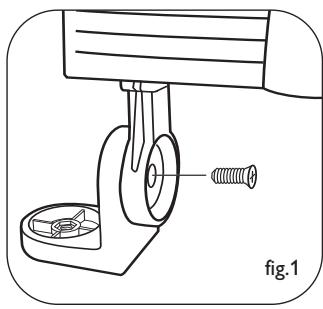
Mechanical assembly diagram showing a lever and screw assembly (no text or symbols)For indoor wall mount installation:
NOTE: Do all antenna assembly work on the ground before installing on a wall or an antenna mast.
- Attach main body to the L - bracket as shown, using cross head screw note the orientation of the bracket. Do not fully tighten the screw to allow for later adjustment (fig. 1).
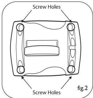
- Using the Wall/Mast bracket as a guide, mark position for the four 2" wood screws. If possible locate a stud to screw into. If a stud is not available, use appropriate wall anchors (not included, available at any hardware store) (fig. 2).
Wall Mount
EN
Mounting Instructions
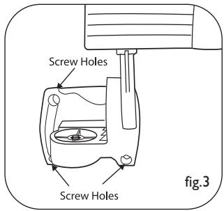
- Attach the main body and L-bracket to wall / mast mounting bracket using cross head screw (fig. 3) note the orientation of the bracket.) Do not fully tighten this screw to allow for later adjustment (fig. 3).
- Tighten all screws and nuts to firmly affix the antenna to the wall.
- Attach the cable to the F connector on the underside of the unit and weather protection boot over the connection.
See next steps under – Connections to your TV
For outdoor mast mount installation:
NOTE: Do all antenna assembly work on the ground. Raise the completed antenna after assembly.
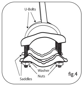
- Insert U-Bolts into the holes of the wall/mast bracket (fig. 4).
- Slide the mast clamps onto the U-Bolts (fig. 4).
- Attach the 4 nuts with lock washers to the U-Bolts - do not tighten fully (fig. 4).
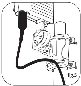
- Slide the assembly on to the mast. Do not tighten fully, just snug enough for the assembly to stay in place (fig. 5).
- Attach the L-Bracket to the wall / mast bracket using cross head screw and nut, Note the orientation of the bracket. Fully tighten this screw.
- Attach the main body of the antenna to L bracket vertically.
- Tighten all screws and nuts to firmly affix the antenna to the mast.
- Adjustment of the antenna direction will be done by rotating the mast in its mount.
- Attach the cable to the 'F' connector on the underside of the unit and weather protection boot over the connection (fig.6).
natural_image
Technical line drawing of a mechanical assembly with no visible text or symbols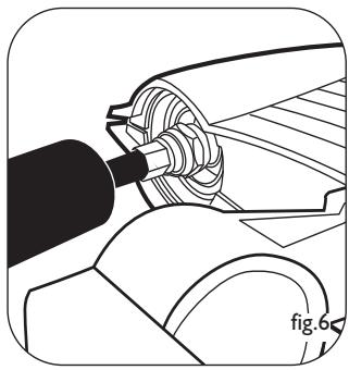
natural_image
Mechanical assembly diagram showing a tool interacting with a car wheel (no text or symbols)Connecting to Your TV
EN

Before You Start
For this antenna to work properly, you must access the menu on the television you are connecting this antenna to (consult your television owner's manual) then set it to receive the signal from an ANTENNA instead of CABLE or SATELLITE.
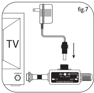
Connections to your TV
As previously noted the amplifier (Power Injector + Power supply) must be placed in-line between the antenna and before any splitter or additional devices.
- Connect the coaxial cable from the antenna to the F connector labeled ANT on the Power Injector.
- Connect Power Injector to the antenna input on your TV, Splitter and / or any other device.
- Connect the Power Supply DC plug to the Power Injector then plug the power supply adapter into a 110/120 Volt AC receptacle.
Safety Note - The power injector and power supply is for indoor use only!
Alternate connections
- If your TV has separate inputs for UHF and VHF you will need to purchase a signal splitter that will separate the two different signals.
- If your TV has only two screw type antenna inputs you will need to purchase a 75 Ohm to 300 Ohm transformer.
A note about coaxial cable – Your SDV2940 includes a 20 foot roll of RG-59 coaxial cable. If you should find that this is not adequate for your needs we recommend for best possible signal integrity that you do not extend this cable. A better choice is to replace the cable with either RG-6 or RG-6 Quad Shield cable. Both of these cables are designed for minimal signal loss over longer cable runs. This will ensure the best possible picture and overall performance.
EN
Warranty
Limited One-Year Warranty
Philips warrants that this product shall be free from defects in material, workmanship and assembly, under normal use, in accordance with the specifications and warnings, for one year from the date of your purchase of this product. This warranty extends only to the original purchaser of the product, and is not transferable. To exercise your rights under this warranty, you must provide proof of purchase in the form of an original sales receipt that shows the product name and the date of purchase. For customer support or to obtain warranty service, please call 919-573-7854. THERE ARE NO OTHER EXPRESS OR IMPLIED WARRANTIES. Philips' liability is limited to repair or, at its sole option, replacement of the product. Incidental, special and consequential damages are disclaimed where permitted by law. This warranty gives you specific legal rights. You may also have other rights that vary from state to state.
Technical Support
For Technical support send an email with the model number of the product and a detailed description of your problem to:
Email: accessorysupport@philips.com
Quality assured in USA
Printed in China
Contenido
ES
natural_image
Mechanical assembly diagram showing a lever and base with a screw, labeled 'fig.1' (no text or symbols on the diagram itself)natural_image
Technical line drawing of a mechanical assembly with no visible text or symbolsES
natural_image
Mechanical assembly diagram showing a shaft and housing component (no text or symbols)Conexiones a su TV
accessorysupport@philips.com
natural_image
Technical line drawing of a mechanical assembly with a spring and base component (no text or symbols)natural_image
Technical line drawing of a mechanical assembly with hoses and components (no text or symbols)natural_image
Mechanical assembly diagram showing a shaft and gear assembly (no text or symbols)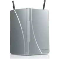
- PHILIPS
- EN
- Contents
- Safety Instructions
- Philips SDV2940
- Indoor/Outdoor UHF/VHF Television antenna
- Antenna grounding
- Important Safety Notes
- IMPORTANT READ BEFORE INSTALLATION
- Important Information
- Important installation information
- Parts Included
- Mounting Instructions
- Determining signal strength
- For indoor wall mount installation:
- For outdoor mast mount installation:
- Connecting to Your TV
- Connections to your TV
- Alternate connections
- Warranty
- Limited One-Year Warranty
- Technical Support
- Contenido
- ES
- Conexiones a su TV
Brand : PHILIPS
Model : SDV2940
Category : TV Antenna