
WX311.1 - Drill WORX - Free user manual and instructions
Find the device manual for free WX311.1 WORX in PDF.

| Product Type | Hammer Drill |
| Brand | WORX |
| Model | WX311.1 |
| Rated Voltage | 220-240 V~, 50/60 Hz |
| Rated Power | 1100 W |
| No Load Speed (Speed 1) | 0-1300 rpm |
| No Load Speed (Speed 2) | 0-2800 rpm |
| Impact Rate (Speed 1) | 0-20800 bpm |
| Impact Rate (Speed 2) | 0-44800 bpm |
| Chuck Capacity | 13 mm |
| Drilling Capacity - Concrete | 20 mm |
| Drilling Capacity - Steel | 16 mm |
| Drilling Capacity - Wood | 40 mm |
| Protection Class | II (Double Insulation) |
| Sound Pressure Level | 92.4 dB(A) |
| Sound Power Level | 103.4 dB(A) |
| Accessories Included | Auxiliary handle, depth gauge, chuck key (WX311), HSS drill bits 5/6/8 mm, screwdriver bits 6/8/10 mm |
| Functions | Drilling, hammer, screwdriving, forward/reverse rotation, variable speed, continuous lock |
| Safety | Double insulation, hearing and eye protection recommended, unplug before maintenance |
| Maintenance and Cleaning | Clean with a dry cloth; do not use water or chemicals; keep ventilation slots clean |
| Spare Parts and Repairability | No user-serviceable parts; contact a professional for power cord replacement |
| General Information | Complies with directives 2006/42/EC and 2004/108/EC; mandatory WEEE recycling |
Frequently Asked Questions - WX311.1 WORX
User questions about WX311.1 WORX
0 question about this device. Answer the ones you know or ask your own.
Ask a new question about this device
Download the instructions for your Drill in PDF format for free! Find your manual WX311.1 - WORX and take your electronic device back in hand. On this page are published all the documents necessary for the use of your device. WX311.1 by WORX.
USER MANUAL WX311.1 WORX
natural_image
Technical line drawing of a drill bit with motion indicators (no text or symbols)A
natural_image
Technical illustration of a drill bit with directional arrow indicating motion (no text or symbols)B
natural_image
Mechanical assembly diagram showing a valve mechanism with rotating arrows (no text or labels)C. 1
natural_image
Mechanical assembly diagram showing a drill bit interacting with a motor (no text or symbols visible)C. 2
D
natural_image
Top-down schematic of a vehicle head and torso showing internal components with an arrow indicating direction (no text or symbols)E
natural_image
Top-down diagram of a vehicle's internal components, showing a central vertical component with horizontal arrows indicating flow or movement (no text or symbols)F
natural_image
Technical line drawing of a mechanical component with no visible text or symbolsG
natural_image
Technical line drawing of a mechanical component with no visible text or symbolsH
- KEYLESS CHUCK (WX311.1)
- DEPTH GAUGE
- GEAR BOX SWITCH
- DRILL/ HAMMER DRILL FUNCTION
- SWITCH LOCK-ON BUTTON
- ON/OFF SWITCH
- AUXILIARY HANDLE
-
KEY CHUCK (WX311)
-
FORWARD AND REVERSE ROTATION CONTROL
Not all the accessories illustrated or described are included in standard delivery.
TECHNICAL DATA
Description WORX Impact drill
Type WX311 WX311.1 (300-329-designation of machinery, representative of impact drill)
| Voltage 220-240V~50/60Hz | ||
| Power input 1100W | ||
| Rated no load speed | Gear 1 0-1300/min | |
| Gear 2 0-2800/min | ||
| Rated impact rate | Gear 1 0-20800bpm | |
| Gear 2 0-44800bpm | ||
| Protection class | ☐/II | |
| Chuck capacity max. | 13mm | |
| Drilling capacity max. | Masonry | 20mm |
| Steel | 16mm | |
| Wood | 40mm | |
| Machine weight | 2.8kg | |
NOISE AND VIBRATION DATA
| A weighted sound pressure 92.4dB(A) | |
| A weighted sound power 103.4dB(A) | |
| K_pA & K_wA | 3.0dB(A) |
| Wear ear protection when sound pressure is over | 80dB(A) [IMAGE] |
VIBRATION INFORMATION
| Vibration total values (triax vector sum) determined according to EN 60745: | |
| Impact drilling into concrete | Vibration emission value a_h.ID = 14.68m/s^2 |
| Uncertainty K = 1.5m/s2 | |
| Drilling into metal | Vibration emission value a_h.D = 2.36m/s^2 |
| Uncertainty K = 1.5m/s2 | |

WARNING: The vibration emission value during actual use of the power tool can differ from the declared value depending on the ways in which the tool is used dependant on
the following examples and other variations on how the tool is used:
How the tool is used and the materials being cut or drilled.
The tool being in good condition and well maintained.
The use the correct accessory for the tool and ensuring it is sharp and in good condition.
The tightness of the grip on the handles and if any anti vibration accessories are used.
And the tool is being used as intended by its design and these instructions.
This tool may cause hand-arm vibration syndrome if its use is not adequately managed.

WARNING: To be accurate, an estimation of exposure level in the actual conditions of use should also take account of all parts of the operating cycle such as the times when
the tool is switched off and when it is running idle but not actually doing the job. This may significantly reduce the exposure level over the total working period.
Helping to minimise your vibration exposure risk.
ALWAYS use sharp chisels, drills and blades.
Maintain this tool in accordance with these instructions and keep well lubricated (where appropriate).
If the tool is to be used regularly then invest in anti vibration accessories.
Avoid using tools in temperatures of 10 ^ or less.
Plan your work schedule to spread any high vibration tool use across a number of days.
ACCESSORIES
Auxiliary handle 1
Depth gauge 1
Chuck key (WX311) 1
Drill bits: HSS - 5, 6, 8mm (Each 1pc) 3
Masonry - 6, 8, 10mm (Each 1pc) 3
We recommend that you buy all your accessories from the store where you purchased the tool. Use good quality accessories marked with a well-known brand name. Refer to 'Working Hints' section in this manual or to the accessory packaging for more details. Store personnel can also help and advise.
ADDITIONAL SAFETY POINTS FOR YOUR DRILL
- Wear ear protectors when impact drilling. Exposure to noise can cause hearing loss.
- Use auxiliary handles supplied with the tool. Loss of control can cause personal injury.
- Hold power tools by insulated gripping surfaces, when performing an operation where the cutting accessory may contact hidden wiring or its own cord. Cutting accessory contacting a "live" wire may make exposed metal parts of the power tool "live" and could give the operator an electric shock.
- Do not use the drill near water.
- Do not use the drill as a screwdriver.
- Remove the plug from the socket before carrying out any adjustment, servicing or maintenance.
- Fully unwind extension cords to avoid potential overheating.
- When an extension cord is required you must ensure it has the correct ampere rating for your power tool and that it is in a safe electrical condition.
- Ensure your supply voltage is the same as your tool rating plate voltage.
- Your tool is double insulated for additional protection against a possible electrical insulation failure within the tool.
- Always check walls and ceilings to avoid hidden power cables and pipes.
- After long working periods, external metal parts and accessories could be hot.
- Wear eye protection when operating this tool.
- Maintain a firm grip on the handle when you are working. Always use the auxiliary handles supplied with the tool. Loss of control can cause personal injury.
SYMBOLS

To reduce the risk of injury, user must read instruction manual

Double insulation

Warning

Wear ear protection

Wear eye protection

Wear dust mask
Waste electrical products must not be disposed of with household waste. Please recycle where facilities exist. Check with your local authorities or retailer for recycling advice.
OPERATING INSTRUCTIONS

NOTE: Before using the tool, read the instruction book carefully.
INTENDED USE
The machine is intended for impact drilling in brick, concrete and stone as well as for drilling in wood, metal and plastic.
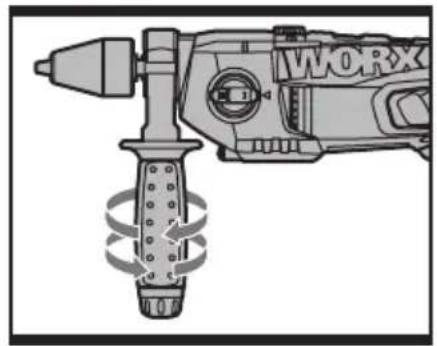
1. AUXILIARY HANDLE (See Fig. A)
Slide the handle onto the drill and rotate to the desired working position. To clamp the auxiliary handle rotates the handgrip clockwise. To loosen the auxiliary handles rotate the hand grip anti-clockwise. Always use the auxiliary handle.

WARNING! Always check and rotate the handle tightly before to avoid any accident.
2. INSTALLING THE DEPTH GAUGE (See Fig. B)
The depth gauge can be used to set a constant depth to drill. To use the depth gauge, loosen the handle by rotating the bottom section of handle anti-clockwise. Insert the depth gauge through hole in handle. Slide the depth gauge to required depth and tighten fully.
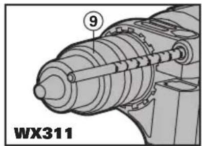
3. INSERTING A TOOL INTO CHUCK (See Fig. C.1&C.2)
KEY CHUCK (9) (WX311)
Remove chuck key from key storage tab at base of drill handle, then place key into chuck, turn key anti-clockwise to undo/loosen chuck, inset drill/tool and firmly tighten chuck by turning key clockwise. Remove key and replace in storage tab at base of drill handle (See Fig C.1).
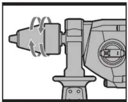
KEYLESS CHUCK (1) (WX311.1)
To open the chuck jaws rotate the front section of the chuck while holding the rear section. Insert the drill bit between the chuck jaws and rotate the front section in the opposite direction while holding the rear section. Ensure that the drill bit is in the center of the chuck jaws. Finally, firmly rotate the two separate chuck sections in opposite directions. Your drill bit is now locked in the chuck. (See Fig C.2)
4. ON/OFF SWITCH
Depress to start and release to stop your tool.
It is also a variable speed switch that delivers higher speed and torque with increased trigger pressure. Speed is controlled by the amount of switch trigger depression.
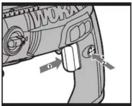
5. SWITCH LOCK-ON BUTTON (See Fig. D)
Depress on/off switch (7) then lock-on button (5), release on/off switch first and lock-on button second. Your switch is now locked on for continuous use. To switch off your tool just depress and release the on/off switch.
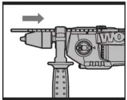
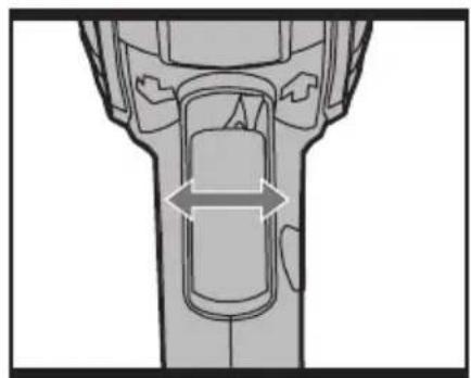
6. FORWARD AND REVERSE ROTATION CONTROL (See Fig. E)
For drilling and screw driving use forward rotation marked “←” (lever is moved to the left). Only use reverse rotation marked “→” (lever is moved to the right) to remove screws or release a jammed drill bit.

WARNING! Never change the direction of rotation when the tool is rotating, until it has stopped.
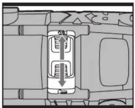
7. HAMMER OR DRILLING CONTROL (See Fig. F)
When drilling masonry and concrete choose the Hammer position “☐” When drilling wood, metal, plastic and screw driving choose the Drill position“☐”.
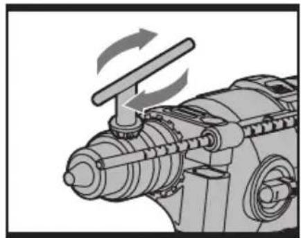
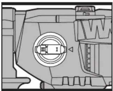
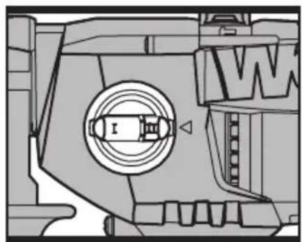
8. GEAR BOX SWITCH
Choose position ■ (See Fig. G) for high torque/low speed range for large diameter drill bits and screw driving. Choose position ■ (See Fig. H)
for low torque/ High-speed range for small diameter drill bits. If the gears do not engage easily then rotate the chuck by hand to align the gears. Never change the gears when the tool is rotating, wait until it has stopped.
WORKING HINTS FOR YOUR DRILL
- If your power tool becomes too hot, set the speed to maximum and run no load for 2-3 minutes to cool the motor.
- Tungsten carbide drill bits should always be used for concrete and masonry.
- When drilling in metal, only use HSS drill bits in good condition.
- Always use a magnetic bit holder when using short screwdriver bits.
- Where possible use a pilot hole before drilling a large diameter hole.
MAINTENANCE
Remove the plug from the socket before carrying out any adjustment, servicing or maintenance.
There are no user serviceable parts in your power tool. Never use water or chemical cleaners to clean your power tool. Wipe clean with a dry cloth. Always store your power tool in a dry place. Keep the motor ventilation slots clean. Keep all working controls free of dust. Occasionally you may see sparks through the ventilation slots. This is normal and will not damage your power tool.
If the supply cord is damaged, it must be replaced by the manufacturer, its service agent or similarly qualified persons in order to avoid a hazard.
TROUBLESHOOTING
- If your power tool does not start, check the plug on the power supply first.
- If the drill is not cutting properly, check the drill bit for sharpness, replace drill bit if worn. Check that the drill is set to forward rotation for normal use.
- If a fault can not be rectified, return the tool to an authorized dealer for repair.
ENVIRONMENTAL PROTECTION
Waste electrical products should not be disposed of with household waste. Please recycle where facilities exist.
Check with your local authorities or retailer for recycling advice.
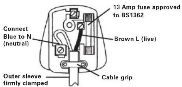
PLUG REPLACEMENT (UK & IRELAND ONLY)
If you need to replace the fitted plug then follow the instructions below.
IMPORTANT
The wires in the mains lead are colored in accordance with the following code:
BLUE = NEUTRAL
BROWN =LIVE
As the colors of the wires in the mains lead of this appliance may not correspond with the colored markings identifying the terminals in your plug, proceed as follows. The wire which is colored blue must be connected to the terminal which is marked with N. The wire which is colored brown must be connected to the terminal which is marked with L.

WARNING!
Never connect live or neutral wires to the earth terminal of the plug. Only fit an approved 13ABS1363/A plug and the correct rated fuse.
NOTE: If a moulded plug is fitted and has to be removed take great care in disposing of the plug and severed cable, it must be destroyed to prevent engaging into a socket.
DECLARATION OF CONFORMITY
We,
POSITEC Germany GmbH
Declare that the product,
Description WORX Impact drill
TypeWX311 WX311.1 (300-329-designation of machinery, representative of impact drill)
Function Boring holes in various materials
Complies with the following directives:
Machinery directive 2006/42/EC
Electromagnetic compatibility directive
2004/108/EC
RoHS Directive 2011/65/EU
Standards conform to:
EN 55014-1
EN 55014-2
EN 61000-3-2
EN 61000-3-3
EN 60745-2-1
EN 60745-1
The person authorized to compile the technical file,
Name: Russell Nicholson
Address: Positec Power Tools (Europe)
Ltd, PO Box 152, Leeds, LS10 9DS, UK


2013/03/25
Leo Yue
POSITEC Quality Manager
Ltd, PO Box 152, Leeds, LS10 9DS, UK


2013/03/25
Leo Yue
INFORMATIONS RELATIVES AUX VIBRATIONS
DÉCLARATION DE CONFORMITÉ
Nous,
POSITEC Germany GmbH
Directive RoHS 2011/65/EU
Et conforme aux norms:
EN 55014-1
EN 55014-2
EN 61000-3-2
EN 61000-3-3
EN 60745-2-1
EN 60745-1
Ltd, PO Box 152, Leeds, LS10 9DS, UK


2013/03/25
Leo Yue
Ltd, PO Box 152, Leeds, LS10 9DS, UK


2013/03/25
Leo Yue
Tipo WX311 WX311.1 (300-329
Endereço Positec Power Tools (Europe) Ltd, PO Box 152, Leeds, LS10 9DS, UK


2013/03/25
Leo Yue
Gestor de Qualidade POSITEC
- SNELSPAN BOORKOP (WX311.1)
- DIEPTEMETER
- VERSNELLINGSSCHAKELAAR
- KLOPBOREN OF BOREN INSTELLING
- SCHAKELAAR VOOR CONTINU GEBRUIK
- DRAAIRICHTING INSTELLING
- AAN/UITSCHAKELAAR
- HANDGREEP VOOR
- BOORHOUDER MET SLEUTEL (WX311)
Type WX311 WX311.1 (300-329
HSS borbits 5, 6,8mm (Hver 1stk.) 3
Murbor 6, 8,10mm (Hver 1stk.) 3
1
Ltd, PO Box 152, Leeds, LS10 9DS, UK
keo.yue
CE
2013/03/25
Leo Yue
N∅KLET CHUCK (9) (WX311)
N∅KKELL∅S CHUCK (1) (WX311.1)
Type WX311 WX311.1 (300-329
-betegner maskin, anger Slagdrill)
Ltd, PO Box 152, Leeds, LS10 9DS, UK


2013/03/25
Leo Yue
HSS-borrbits 5, 6,8mm (Varje 1 st) 3
Betongborr 6, 8,10mm (Varje 1 st) 3
Ltd, PO Box 152, Leeds, LS10 9DS, UK
leo.yue
CE
2013/03/25
Leo Yue
ANAHTARLI AYNA (9) (WX311)
Ilgi Positec Power Tools (Europe) Ltd,
PO Box 152, Leeds, LS10 9DS, UK


2013/03/25
Leo Yue
(Europe) Ltd, PO Box 152, Leeds, LS109DS, UK
keo.yue
CE
2013/03/25
Leo Yue
Ltd, PO Box 152, Leeds, LS10 9DS, UK
keo.yue
CE
2013/03/25
Leo Yue
you've got the power
Copyright © 2014, Positec. All Rights Reserved. 2PDI09APK11004A4

- TECHNICAL DATA
- NOISE AND VIBRATION DATA
- VIBRATION INFORMATION
- This tool may cause hand-arm vibration syndrome if its use is not adequately managed.
- ACCESSORIES
- ADDITIONAL SAFETY POINTS FOR YOUR DRILL
- SYMBOLS
- OPERATING INSTRUCTIONS
- INTENDED USE
- AUXILIARY HANDLE (See Fig. A)
- INSTALLING THE DEPTH GAUGE (See Fig. B)
- INSERTING A TOOL INTO CHUCK (See Fig. C.1&C.2)
- KEY CHUCK (9) (WX311)
- KEYLESS CHUCK (1) (WX311.1)
- ON/OFF SWITCH
- SWITCH LOCK-ON BUTTON (See Fig. D)
- FORWARD AND REVERSE ROTATION CONTROL (See Fig. E)
- HAMMER OR DRILLING CONTROL (See Fig. F)
- GEAR BOX SWITCH
- WORKING HINTS FOR YOUR DRILL
- MAINTENANCE
- Remove the plug from the socket before carrying out any adjustment, servicing or maintenance.
- TROUBLESHOOTING
- ENVIRONMENTAL PROTECTION
- PLUG REPLACEMENT (UK & IRELAND ONLY)
- IMPORTANT
- BLUE = NEUTRAL
- BROWN =LIVE
- WARNING!
- DECLARATION OF CONFORMITY
- INFORMATIONS RELATIVES AUX VIBRATIONS
- DÉCLARATION DE CONFORMITÉ
- N∅KLET CHUCK (9) (WX311)
- N∅KKELL∅S CHUCK (1) (WX311.1)
- ANAHTARLI AYNA (9) (WX311)
Brand : WORX
Model : WX311.1
Category : Drill