
WX424.3 - Saw WORX - Free user manual and instructions
Find the device manual for free WX424.3 WORX in PDF.
| Product type | Mini multi-purpose saw |
| Brand | Worx |
| Model | WX424.3 |
| Rated voltage | 230-240 V ~ 50 Hz |
| Power consumption | 310 W |
| No-load speed | 2800 min⁻¹ |
| Blade diameter | 76 x 10 mm |
| Max cutting depth | 22 mm |
| Weight | 1.5 kg |
| Double insulation | Yes |
| Sound pressure level | 82 dB(A) |
| Sound power level | 93 dB(A) |
| Vibration emission value | 6.01 m/s² (K=1.5 m/s²) |
| Laser | Class 2, 1 mW, 650 nm |
| Work LED light | Yes |
| Adjustable handle | 3 positions (0°, 15°, 30°) |
| Scratch-proof base cover | Included |
| Parallel guide | Included |
| Vacuum adapter | Included |
| Blades provided | 24T TCT (wood), 44HSS (general purpose), diamond disc 50# (depending on version) |
| Compatible materials | Wood, aluminum, PVC, tiles |
| Maintenance and cleaning | Clean with a dry cloth; do not use water or chemical cleaners |
| Repairability | No user-serviceable parts; contact the manufacturer for any repairs |
| Additional accessories | Hex key for blade change |
Frequently Asked Questions - WX424.3 WORX
User questions about WX424.3 WORX
0 question about this device. Answer the ones you know or ask your own.
Ask a new question about this device
Download the instructions for your Saw in PDF format for free! Find your manual WX424.3 - WORX and take your electronic device back in hand. On this page are published all the documents necessary for the use of your device. WX424.3 by WORX.
USER MANUAL WX424.3 WORX
*Not all the accessories illustrated or described are included in standard delivery.
TECHNICAL DATA
Description WORKX Mini multi-function saw
Type WX424 WX424.1 WX424.2 WX424.3 (4-Designation of machinery, representative of saw)
| Voltage 230-240V~50Hz |
| Power input 310W |
| No load speed 2800/min |
| Blade diameter 76x10mm |
| Cutting capacity 22mm |
| Protection class |
| Machine weight 1.5kg |
NOISE AND VIBRATION DATA
| A weighted sound pressure L | 82dB(A) |
| A weighted sound power L | 93dB(A) |
| KPA&KWa | 3dB(A) |
| Wear ear protection when sound pressure is over 80dB(A) | |
VIBRATION INFORMATION
| Vibration total values (triax vector sum) determined according to EN 60745: | |
| Typical weighted vibration | Vibration emission value ah = 6.01m/s2 |
| Uncertainty K = 1.5m/s2 | |

WARNING: The vibration emission value during actual use of the power tool can differ
from the declared value depending on the ways in which the tool is used dependant on the
following examples and other variations on how the tool is used:
How the tool is used and the materials being cut or drilled.
The tool being in good condition and well maintained
The use the correct accessory for the tool and ensuring it is sharp and in good condition.
The tightness of the grip on the handles and if any anti vibration accessories are used.
And the tool is being used as intended by its design and these instructions.
This tool may cause hand-arm vibration syndrome if its use is not adequately managed

WARNING: To be accurate, an estimation of exposure level in the actual conditions of
use should also take account of all parts of the operating cycle such as the times when
the tool is switched off and when it is running idle but not actually doing the job. This may
significantly reduce the exposure level over the total working period.
Helping to minimise your vibration exposure risk.
ALWAYS use sharp chisels, drills and blades.
Maintain this tool in accordance with these instructions and keep well lubricated (where appropriate).
If the tool is to be used regularly then invest in anti vibration accessories.
Avoid using tools in temperatures of 10^ or less.
Plan your work schedule to spread any high vibration tool use across a number of days.
ACCESSIONS
| wx424 | wx424.1 | wx424.2 | wx424.3 | ||
| Vacuum adaptor 1 1 1 | |||||
| Non-scratch base cover 1 1 1 | |||||
| Parallel guide 1 1 1 | |||||
| Hex key 2 2 2 | |||||
| Hex key | 24T TCT for wood 1 2 1 | ||||
| 44T HSS for general blade 1 1 | / | ||||
| 50grit diamond disc | 1 1 / | ||||
We recommend that you purchase your accessories from the same store that sold you the tool. Use good quality accessories marked with a well-known brand name. Choose the type according to the work you intend to undertake. Refer to the accessory packaging for further details. Store personnel can assist you and offer advice.
ADDITIONAL SAFETY RULES FOR YOUR MINI MULTI-FUNCTION SAW
- Always wear a dust mask, hearing protection and eye protection.
- Only use saw blades recommended for use with this model.
- Always wear gloves when handling saw blades and rough material. Saw blades shall be carried in a holder whenever practicable.
- Fully unwind cable drum extension to avoid potential overheating.
- When an extension cable is required you must ensure it has the correct ampere rating for your power tool and is in a safe electrical condition.
- Ensure your mains supply voltage is the same as indicated on the rating plate.
- Your mini multi-function saw is a hand held tool, do not clamp your mini multi-function saw to a workbench.
- Before cutting, ensure the work piece is free of nails, screws, etc.
- Do not cut small work pieces with a mini multi-function saw. If possible, use a jigsaw.
- Only make cuts with the blade direction downwards, never upwards or at the side.
- Do not use a blade unless the rated blade speed exceeds the saw no load speed.
- Never remove the guard system. Never use the saw if the guard system does not function correctly. Never lock the moving guard open. The guard must move freely.
- Always check walls, floors and ceilings to avoid hidden power cable and pipes.
- After long working periods external metal parts and accessories could be hot.
- Do not cut material containing asbestos.
- Do not use mini multi-function saw to cut tree limbs or logs.
- Do not use any abrasive wheels.
SAFETY INSTRUCTIONS FOR ALL SAWS

WARNING
- Keep hands away from the cutting area and the blade. Keep your second hand on the motor housing. If both hands are holding the saw, they can not be cut by the blade.
- Do not reach underneath the work
piece. The guard cannot protect you from the blade below the work-piece.
- Adjust the cutting depth to the thickness of the work-piece. Less than a full tooth of the blade teeth should be visible below the work-piece.
- Never hold piece being cut in your hands or across your leg. Secure the work-piece to a stable platform. It is important to support the work properly to minimize body exposure, blade binding, or loss of control.
- Hold power tool by insulated gripping surfaces when performing an operation where the cutting tool may contact hidden wiring or its own cord.
Contact with a "live" wire will Iso make exposed metal parts of the power tool "live" and shock the operator.
- When ripping always use a rip fence or straight edge guide. This improves the accuracy of cut and reduces the chance of blade binding.
- Always use blades with correct size and shape of arbor holes. Blades that do not match the mounting hardware of the saw will run eccentrically, causing loss of control.
- Never use damaged or incorrect blade washers or bolt. The blade washers and bolt are specially designed for your saw, for optimum performance and safety of operation.
FURTHER SAFETY INSTRUCTIONS FOR ALL SAWS.
CAUSES AND OPERATOR PREVENTION OF KICKBACK:
- Kickback is a sudden reaction to pinched, bound or misaligned saw blade, causing an uncontrolled saw to lift up and out of the work-piece toward the operator;
- When the blade is pinched or bound tightly by the work piece being cut, the blade stalls and the motor reaction drives the unit rapidly back toward the operator;
- If the blade becomes twisted or misaligned in the cut, the teeth at the back edge of the blade can dig into the top surface of the wood causing the blade to climb out of the material being cut and jump back toward the operator.
KICKBACK IS THE RESULT OF SAW MISUSE AND/OR INCORRECT OPERATING PROCEDURES OR CONDITIONS AND CAN BE AVOIDED BY TAKING PROPER PRECAUTIONS AS GIVEN BELOW.
- Maintain a firm grip with both hands on the saw and position your arms to resist kickback forces. Position your body to either side of the blade, but not in line with the blade. Kickback could cause the saw to jump backwards, but kickback forces can be controlled by the operator, if proper precautions are taken.
- When blade is binding, or when interrupting a cut for any reason, release the trigger and hold the saw motionless in the material until the blade comes to a complete stop. Never attempt to remove the saw from the work or pull the saw backward while the blade is in motion or kickback may occur. Investigate and take corrective actions to eliminate the cause of blade binding.
- When restarting a saw in the workpiece, center the saw blade in the work piece cut and check that saw teeth are not engaged into the material. If saw blade is binding, it may walk up or kickback from the work-piece as the saw is restarted.
- Support large panels to minimize the risk of blade pinching and kickback.
Large panels tend to sag under their own weight. Supports must be placed under the panel on both sides, near the line of cut and near the edge of the panel.
- Do not use dull or damaged blades. Unsharpened or improperly set blades can cause excessive friction, blade binding and kickback.
- Blade depth and bevel adjusting locking levers must be tight and secure before making cut. If blade adjustment shifts while cutting, it may cause binding and kickback.
- Use extra caution when making a "plunge cut" into existing walls or other blind areas. The protruding blade may cut objects that can cause kickback.
SAFETY INSTRUCTION FOR MINI MULTIFUNCTION SAW WITH LOWER GUARD
- Check lower guard for proper closing before each use. Do not operate the saw if lower guard does not move freely and close instantly. Never clamp or tie the lower guard into the open position. If saw is accidentally dropped, lower guard may be bent. Raise the lower guard with the retracting handle and make sure it moves freely and does not touch the blade or any other parts, in all angles and depths of cut.
- Check the operation of the lower guard spring. If the guard and the spring are not operating properly, they must be serviced before use.
Lower guard may operate sluggishly due to damaged parts, gummy deposits, or a build-up of debris.
- Assure that the guide plate of the saw will not shift while performing the "plunge cut" when the blade bevel setting is not at 90^ . Blade shifting sideways will cause binding and likely kick back.
- Always observe that the lower guard is covering the blade before placing saw down on bench or floor. An
unprotected, rotating blade will cause the saw to walk backwards, cutting whatever is in its path. Be aware of the time it takes for blade to stop after ON/OFF switch is released.
GENERAL SAFETY WARNINGS FOR YOUR LASER
WARNING: Read all safety warnings and all instructions. Failure to follow
the warnings and instructions may result in serious injury.
Save all warnings and instructions for future reference.
These lasers do not normally present an optical hazard although staring at the beam may cause flash blindness.
Do not stare directly at the laser beam. A hazard may exist if you deliberately stare
into the beam, please observe all safety rules as follows:
- The laser shall be used and maintained in accordance with the manufacturer's instructions.
- Never aim the beam at any person or an object other than the work piece.
- The laser beam shall not be deliberately aimed at another person and shall be prevented from being directed towards the eye of a person for longer than 0.25 seconds.
- Always ensure the laser beam is aimed at a sturdy work piece without reflective surfaces, e.g wood or rough coated surfaces are acceptable. Bright shiny reflective sheet steel or similar is not suitable for laser applications as the reflective surface may direct the laser beam back at the operator.
- Do not change the laser device with a different type. Repairs must be carried out by the manufacturer or an authorized agent.
- CAUTION: Use of controls or adjustments other than those specified herein may result in hazardous radiation exposure.
Additional safety warning for class 2 laser
The laser device fitted to this tool is class 2 with a maximum radiation of 1mW and 650nm wavelength.
CLASS 2 LASER RADIATION, DO NOT STARE INTO BEAM
SYMBOLS

To reduce the risk of injury, user must read instruction manual

Warning

Double insulation

Wear eye protection

Wear ear protection

Wear dust mask
Waste electrical products should not be disposed of with household waste. Please recycle where facilities exist. Check with your Local Authority or retailer for recycling advice.
Laser radiation
Do not stare into beam
OPERATING INSTRUCTIONS

NOTE: Before using the tool, read the instruction book carefully.
INTENDED USE:
The machine is intended for lengthways and crossways cutting of wood with straight cutting lines, aluminium, PVC pipe and tile, etc., while resting firmly on the work piece.
1. INSTALL/CHANGE THE BLADE (See Fig. A)
WARNING: Be sure to wear protective work gloves while handling a saw blade. The blade can injure unprotected hands.
WARNING: This tool will be extremely hot after use. Be sure to let saw, blade and blade spindle clamping screw cool before changing blades.
a. Unplug the saw.
WARNING: To prevent personal injury, Always disconnect the plug from power source before assembling parts, making adjustments or changing blades.
b. Loosen the blade spindle clamping screw using the two hex keys included. Place one key into the blade spindle clamping screw and the other key into the back of the spindle assembly. (See Fig. A)
c. Turn the key that is in the clamping screw clockwise while holding the other key stationary.
d. Remove the screw and the blade clamping washer. (See Fig. B)
e. Set the depth of cut scale to the maximum depth of 22mm . Release the blade release lever and rasie the base with the finger lift bracket to expose the blade below the base.
f. Grasp the blade with your gloved hand and remove the blade, or install the blade, through the blade slot in the base.
g. Place the new saw blade through the blade slot in the base and onto the spindle shaft.
NOTE: The teeth of the blade should
point upward at the front of the saw as shown in (See Fig. B).
NOTE: The warning copy and the Blade Rotation Arrow shown on the blade should face outward towards the operator so it can be viewed (See Fig. C).
h. Replace the blade clamping washer .
i. Replace the spindle screw and hand tighten it in a counterclockwise direction.
j. Use the two hex keys to tighten the spindle clamping screw thoroughly.
k. Place the two hex keys back in the case.
NOTE: Never use a blade that is too thick to allow the blade clamping washer to engage with the flat side of the spindle.
2. MAKING DEPTH OF CUT ADJUSTMENTS (See Fig. D)
NOTE: Always use the correct blade depth setting. The correct blade depth setting for all cuts should not be more than 6mm below the material being cut. Allowing more depth will increase the chance of kickback and cause the cut to be rough. Your saw is equipped with a depth of cut scale that provides increased depth of cut accuracy. The depth of cut scale is located on the top of the upper blade guard (See Fig. D).
Our suggest cut depth:
| Max. cut depth | |
| Wood 0-22mm | |
| Alu 0-3mm | |
| PVC pipe 0-12mm | |
| Tile 0-8mm |
TO SET THE BLADE DEPTH (Fig. E1, E2)
Determine the desired depth of cut. Unlock the depth of cut and length of cut Indicator adjustment/Lock lever. Slide the depth of cut indicator to the desired depth of cut. Lock down the depth of cut adjustment / lock lever. The length of cut indicator (See Fig.D) is ideal for plunge or pocket cutting into the middle (or interior) of the work piece when you need to know where the cut will begin and where it will end. This feature allows you to pinpoint the location where the blade will plunge into the work piece, based on the blade depth that
was selected. Always practice in a scrap work piece to become familiar with this cutting operation. The selected depth of cut is now set. When the saw's blade is manually lowered (See Fig. Ka, Kb), the blade will be below the base at the selected depth.
3. ADJUSTING THE 3-POSITION HANDLE (See Fig. F)
Your saw has handle/motor housing with soft-grip that adjusts to 3 different cutting angles, 0^ , 15^ , and 30^ . This feature provides more efficient cutting angles for various applications and added gripping comfort with maximum control.
Grasp the handle with one hand and push the handle adjustment button "IN" to release the handle for adjustment. Move the handle forward or backward (See Fig. F) to locate the 3 different positions. When the handle moves into 1 of the 3 positions the adjustment button will snap out and the handle will lock into position. When adjusting the handle, Always be sure that the button has snapped out and the handle is locked in position. If the handle still moves forward or backward, repeat the process until the handle is locked securely in position.
WARNING: Do not operate the saw if the handle IS not locked in position and can still move forward or backward. Failure to lock the handle in 1 of 3 cutting positions could cause loss of control of saw and result in serious injury.
4. TRIGGER SWITCH (See Fig. G)
To activate the trigger switch to turn the saw "ON", place your index and middle fingers into the molded finger grip trigger safety release switch, and the other two fingers on the trigger paddle (See Fig. G). Squeeze the finger grip "back" until it "clicks", then depress the trigger paddle to turn the saw "ON". To stop the saw, release your grip on the trigger paddle, and the finger grip safety release switch will move back into the "OFF" position.
5. USING THE LASER LIGHT FEATURE AND LED WORKLIGHT (See Fig. H, I)
WARNING: DO NOT stare into beam. Only turn laser beam on when the saw is on the work piece.
Your saw has a built-in laser light. To activate laser light switch, saw must be plugged into power source.
a. Do not turn the laser beam on until the saw is on the work piece.
b. Mark the line of cut on the work piece.
c. Adjust the cutting angle and cutting depth as needed.
d. Plug in the saw and push the laser switch forward to turn on the laser.
e. Always shut off the laser light when you are finished cutting.
f. Your circular saw has a built-in work light for better visibility when cutting. To turn on the LED work light, the saw must be plugged in. Push the switch from OFF to LED.
6. STARTING A CUT (See Fig. J,K,L1,L2)
a) Set-up and clamp your work piece and mark your cut line.
b) Set the handle on the saw to the desired angle for your cutting application.
c) Set the depth of cut (with corresponding length of cut).
d) Position the front of the saw's base onto the leading end (edge) of the work piece that is solidly supported. Align the center of the "V" notch on the front of the base with the cut line (See Fig. J).
e) Manually release the blade guard release lever while holding the finger lift bracket on the rear of the base (See Fig. Ka, Kb) as you lower the saw's handle and blade to the selected depth.
Make sure the blade is not making contact with the workpiece.
f) With both hands on the handle, squeeze the trigger's molded finger grip safety release "backward" while squeezing down on the paddle switch to turn the saw "On".
g) Let the blade reach full speed before you enter the work piece, starting your cut.
h) Press down on the saw, keeping the front
of the base flat against the work piece as you slowly push the saw's blade into the work piece (See Fig. Kc).
i) Carefully guide the saw through the line of cut. Do not bind the blade in the cut; push the saw blade forward at a rate where the blade is not laboring. When the cut is complete, release the trigger safety release and paddle switch and let the blade come to a complete stop. Do not remove the saw and blade from the work piece while the blade is moving. This could damage your cut, cause kickback, loss of control and result in serious injury.
j) When the blade and saw are clear of and removed from the work piece (See Fig. Kf), the lower blade guard and base will be able to automatically drop down and the blade guard release lever will engage the upper blade guard, locking the blade above the base (See Fig. Kg).

Fig. L2.
WARNING: Never use the saw with your hands positioned as shown in
7. MAKING CROSS CUTS AND RIP CUTS (See Fig. M1, M2)
a) ALWAYS use your saw with your hands positioned correctly (See Fig. M1, M2).

WARNING: Always maintain proper control of the saw to make long safer and easier. Loss of control, if the saw could cause an accident, eating in possible serious injury.
b) When making cross or rip cuts, align your line of cut with the center of the "V" notch located on the front of the saw's base (See Fig. J).
c) Since the thickness of blades varies, make a trial cut in scrap material along the guideline to determine how much, if any, you should offset the blade from the guideline to allow for the blade thickness to get an accurate cut.
Making rip cuts (See Fig. M2)
Always use a guide when making long or wide rip cuts with your saw. You can use either a straight edge (sold separately), or use the parallel guide that is included with your saw.
8. CUTTING WITH A STRAIGHT EDGE (See Fig. M1)
You can make an efficient rip guide by clamping a straight edge to your work piece.
a) Mark the position of the side edge of the saw's base (cutting platform) and then securely clamp the straight edge (sold separately) on the mark and parallel to the cut line.
b) As you cut, keep the edge of the saw's base flush against the straight edge and flat on the work piece.
c) Always let the blade reach full speed, then carefully guide the saw into the work piece. Do not bind the blade in the cut. Push the saw forward at a speed where the blade is not laboring.
9. INSTALLING AND USING THE PARALLEL GUIDE (See Fig. N1,N2,N3)
Your saw comes with a parallel guide that is 7-inches long on the guide edge. It allows you to make accurate parallel cuts when trimming a work piece. It attaches to the saw's base. The arm of the parallel guide is stamped, on both sides, 0 to 7 inches in 1/4-inch increments and 1 to 18 centimeters in 10-mm increments for easy adjustment of your cut. The parallel guide can be used with the guide edge turned down to guide along the edge of a work piece for rip or cross cuts (See Fig. N2), or turned up to guide against a wall for inside cuts (See Fig. N3).
a) Position the parallel guide so the arm can slide into the mounting slots at the front of the saw's base (See Fig. N1), and loosen the retaining screw.
b) Adjust the parallel guide to the desired length of cut.
c) Tighten the parallel guide locking screw(20).
d) Clamp and support the work piece securely before making your cut.
e) Place the parallel guide firmly against the edge of the work piece (See Fig.N2), or against a wall (See Fig.N3). Doing this will help give you a true cut without pinching the blade.
f) Be sure that the guiding edge of the work piece, or the wall, is straight so you can
produce a straight cut (See Fig. N2,N3).
g) Always let the blade reach full speed, then carefully guide the saw into the work piece. Do not bind the blade in the cut. Push the saw forward at a speed where the blade is not laboring.
Cutting into a solid base surface
One of the major benefits of this saw is its ability to make plunge cuts directly into the middle, or interior of a work piece, or plunge cut directly into a solid base surface such as sub-flooding, siding, paneling and hardwood or laminate flooring that is mounted on top of sub-flooding.
a) Mark the cut line on the surface to be cut.
b) Set the depth of cut to the thickness of the material to be cut, (sub/floor, siding, laminate flooring, etc.)
c) Align (position) the saw base on the work piece to your mark, using the length of cut guide (so that your starting point lines up with the mark corresponding to the depth of cut setting (See Fig. D).
d) Activate the trigger safety release and paddle switches and turn the saw "On".
e) Let the blade reach full speed.
f) Manually release the blade guard release lever while holding the finger lift bracket on the rear of the base (See Fig. Oa).
g) A. Slowly lower the blade into the work piece.
B. Carefully guide the saw through the line of cut until the forward depth marking on the length of cut guide located on the saw's base aligns with the end of cut marking on your work piece. (Do not bind the blade in the cut; push the saw blade forward at a rate where the blade is not laboring).
C. When the cut is complete, release the trigger safety release and paddle switch and let the blade come to a complete stop. Do not remove the saw and blade from the work piece while the blade is moving. This could damage your cut, cause kickback and loss of control, resulting in serious injury.
h) When the blade and saw are clear of and removed from the work piece, the lower
blade guard and base will be able to automatically drop down and the blade guard release lever will engage the upper blade guard, locking the blade above the base.
11. SAWDUST REMOVAL (See Fig. Q)
Your saw includes a hose adapter tube that attaches to the built-in dust extraction port (7) on the saw (See Fig. 0). This adapter tube can be attached to a wet/dry vacuum cleaner (sold separately). This will help remove dust, chips and cutting debris away from the cutting area.
12. NON-SCRATCH BASE COVER (See Fig. R)
Your saw includes a non-scratch base cover (19). Attach it to your saw's base when you are cutting work pieces that have delicate surfaces (finishes) such as vinyls, plastics, fiberglass, laminate flooring and tiles that could easily be scratched or scraped with the steel base on the saw.
WORKING HINTS FOR YOUR TOOL
If your power tool becomes too hot, please run your circular saw no load for 2-3 minutes to cool the motor. Avoid prolonged usage at very low speeds.
Protect saw blades against impact and shock. Excessive feed significantly reduces the performance capability of the machine and reduces the service life of the saw blade.
Sawing performance and cutting quality depend essentially on the condition and the tooth form of the saw blade. Therefore, use only sharp saw blades that are suited for the material to be worked.
MAINTENANCE
Remove the plug from the socket before carrying out any adjustment, servicing or maintenance.
Your power tool requires no additional lubrication or maintenance. There are no user serviceable parts in your power tool. Never
use water or chemical cleaners to clean your power tool. Wipe clean with a dry cloth. Always store your power tool in a dry place. Keep the motor ventilation slots clean. Keep all working controls free of dust. Occasionally you may see sparks through the ventilation slots. This is normal and will not damage your power tool.
If the supply cord is damaged, it must be replaced by the manufacturer, its service agent or similarly qualified persons in order to avoid a hazard.
ENVIRONMENTAL PROTECTION
Waste electrical products should not be disposed of with household waste.
Please recycle where facilities exist.
Check with your local authorities or retailer for recycling advice.
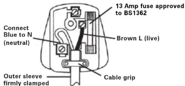
PLUG REPLACEMENT (UK & IRELAND ONLY)
If you need to replace the fitted plug then follow the instructions below.
IMPORTANT
The wires in the mains lead are colored in accordance with the following code:
Blue = Neutral
Brown = Live
As the colors of the wires in the mains lead of this appliance may not correspond with the coloured markings identifying the terminals in your plug, proceed as follows. The wire which is coloured
blue must be connected to the terminal which is marked with N. The wire which is coloured brown must be connected to the terminal which is marked with L.

WARNING: Never connect live or
neutral wires to the earth terminal of the
plug. Only fit an approved BS1363/A plug and the correct rated fuse.
NOTE: If a moulded plug is fitted and has to be removed take great care in disposing of the plug and severed cable, it must be destroyed to prevent engaging into a socket.
DECLARATION OF CONFORMITY
We,
POSITEC Germany GmbH
Declare that the product,
Description WORX Mini multi-function saw
Type WX424 WX424.1 WX424.2
WX424.3 (4-Designation of machinery, representative of saw)
Function Cutting various materials with a rotating toothed blade
Complies with the following directives,
Machinery directive 2006/42/EC
Electromagnetic compatibility directive
2004/108/EC
RoHS directive 2011/65/EU
Standards conform to
EN 55014-1
EN 55014-2
EN 61000-3-2
EN 61000-3-3
EN 60745-2-5
EN 60745-1
EN 847-1
The person authorized to compile the technical file,
Name Russell Nicholson
Address Positec Power Tools (Europe)
Ltd, PO Box 152, Leeds, LS10 9DS, UK


2012/10/22
Leo Yue
POSITEC Quality Manager
Typ WX424 WX424.1 WX424.2
Ltd, PO Box 152, Leeds, LS10 9DS, UK


2012/10/22
LeoYue
INFORMATIONS RELATIVES AU BRUIT
INFORMATIONS RELATIVE AUX VIBRATIONS
SYMBOLS FONCTIONNEMENT

Modèle WX424 WX424.1 WX424.2
Directive RoHS 2011/65/EU
Ltd, PO Box 152, Leeds, LS10 9DS, UK


2012/10/22
Leo Yue
Responsible qualite POSITEC
- IMPUGNATURA MORBIDA
- ALLOGGIAMENTO MOTORE
- IMPUGNATURA SUPPLEMENTARE
- SCALA DI PROFONDITA DI TAGLIO
- LEVA RILASCIO PROTEZIONE
- STAFFA SOLLEVAMENTO AZIONABILE CON DITO
- TUBO PER ASPIRAZIONE POLVERI (Vedere Figura Q)
- PROTEZIONELAMA INFERIORE
- PROTEZIONE SUPERiore DELLA LAMA
- SCALA INDICATORE LUNGHEZZA DEL TAGLIO
- RONDELLA BLOCCAGGIO LAMA
- VITE BLOCCAGGIO ASSE
- APERTURE PER IL MONTAGGIO DELLA GUIDA PARALLELA
- PROFONDITA' DELLA LEVA PER IL BLOCCO TAGLIO
- GUIDA LASER E LUCE LED
- PULSANTE REGOLAZIONE IMPUGNATURA
- INTERRUPTORE ON/OFF LASER E LED
- PIASTRA
- COPERTURA BASE ANTIGRAFFIO (Vedere Figura R)
- VITE BLOCAGGIO GUIDA PARALLELA (Vedere Figura N1)
Codice WX424 WX424.1 WX424.2
Ltd, PO Box 152, Leeds, LS10 9DS, UK


2012/10/22
Leo Yue
Modelo WX424 WX424.1 WX424.2
WX424.3 (4-Denominaciones de
Ltd, PO Box 152, Leeds, LS10 9DS, UK


2012/10/22
Leo Yue
9. INSTALLação E UTILIZATION DA GUI PARALELA (Ver Fig. N1,N2,N3)
Tipo WX424 WX424.1 WX424.2
Ltd, PO Box 152, Leeds, LS10 9DS, UK


2012/10/22
Leo Yue
Gestor de Qualidade POSITEC
| 1. ZACHTE HANDGREEP |
| 2. MOTORBEHUIZING |
| 3. AAN/UIT-SCHAKELAAR |
| 4. SCHAAL VOOR ZAAGDIEPTE |
| 5. VERGRENDELKNOP VAN DE KAP |
| 6. BEUGEL OM MET DE VINGER OP TE TILLEN |
| 7. STOFBUISJE (Zie Afbeelding Q) |
| 8. ONDERSTE BESCHERMKAP |
| 9. BOVENSTE MESKAP |
| 10. LENGTHEN ZAAGINDICATORSCHAAL |
| 11. RING VAN MESKLEM |
| 12. SCHROEF OM AS VAST TE KLEMMIEN |
| 13. MONTAGEGLEUVEN VOOR PARALLELGELEIDER |
| 14. BLOKKEERHENDEL VOOR ZAAGDIEPTE |
| 15. LASERGELEIDING EN LEDVERLICHTING |
| 16. INSTELKNOP VAN HANDVAT |
| 17. SCHAKELAAR VOOR LADER EN LED |
| 18. VOETPLAAT |
| 19. VOETBESCHERMERS (Zie Afbeelding R) |
| 20. BLOKKEERSCHROEF VAN PARALLELLLE GELEIDER (Zie Afbeelding N1) |
WAARSCHUWING! Lees alle
TIPS VOOR HET WERKEN MET UW APPARAAT
Type WX424 WX424.1 WX424.2
Ltd, PO Box 152, Leeds, LS10 9DS, UK


2012/10/22
Leo Yue
Type WX424 WX424.1 WX424.2 WX424.3 (4- Udpegning af maskiner, representant for saw)
2.INDSTILLING AF SAVEDYBDE (Se Fig.D)
Type WX424 WX424.1 WX424.2
WX424.3 (4-UdPEGing af maskiner,
representant for saw)
Funktion Skaering forskeigige materialer
med en roterende tandede savklinge
Ltd, PO Box 152, Leeds, LS10 9DS, UK


2012/10/22
Leo Yue
Type WX424 WX424.1 WX424.2 WX424.3 (4-Betegner maskin, angir sag)
A stille inn bladdybde (Se E1, E2)
9. MONTERING OG BRUK AV PARALLELLSKINNE (Se N1,N2,N3)
Sagen leveres med en parallellskinne som er nesten 18 cm lang pa skinnekanten. Den kan brukes til a lage noyaktige parallelle kutt nar du beskjærer et arbeidsemne. Den festes til sagens sukkel. Armen pa kantskinnen har pa begge sider merker fra 0 til 7 tommer med 1/4 tommers-intervaller og 1 til 18 centimeter med 10 mm-intervaller for lett justering av kuttet. Parallelskinnen kan brukes med skinnekanten nedover for en kant pa et arbeidsemne enten for kapping ellr for klvying (Se N2), men ogsa oppover som en styreskinne mot en vegg forindre kutt (Se N3).
a) Plasser parallelskinnen slick at armen kan smette inn i monteringshullene foran på sagens sukkel (Se N1), og Iøsne festeskruen.
b) Juster parallelskinen til riktig skjærelengde.
c) Stram til festeskruen pa parallellskinnen(20).
d) Klem fast arbeidsemnet for du begyinner skjaeringen.
e) Plasser parallellskinen skikkelig mot kanten på arbeidsemnet (Se N2), aller mot en vegg (Se N3). Ved Å gjore dette kan du få et riktig kutt uten Å klemme bladet.
f) Kontroller at styrekanten på arbeidsemnet aller veggen er rett, sik at det gir et rett kutt (Se N2,N3).
g) La alltid bladetkommenoppifull hastighet,ogfordet sa forsiktig gjennom arbeidsemnet. Ikke sett fast bladetikuttet. FOr sagen fremover med en hastighet som gjor at bladet icke sliter.
10. SENKINGS- ELLER LOMMESKJAERING (Se Oa,Ob,Oc)
ARBETSTIPPS FÖR DIT VERKTYG
Typ WX424 WX424.1 WX424.2 WX424.3
Ltd, PO Box 152, Leeds, LS10 9DS, UK


2012/10/22
Leo Yue
POSITEC Kvalitetsdirektor
136
- YUMUŞAK TUTMA YERİ
- MOTOR YERI
- EMNIYET ACMA/KAPAMA ANAHTARI
- KESME SKALASI DERINLIGI I
- KORUYUCU SERBEST BIRAKMA KOLU
- PARMAK KALDIRMA BRAKETI
- TOZ BORUSU (Bkz. Sek Q)
- ALT BICAK SIPERLIJI
- ÜST BICAK KORUYUCU
- KESME GÖSTERGE ÖLÇEGİNIN UZUNLUğU
- BICAK KENETLEME RONDELASI
12.IG KENETLEME VIDASI - PARALEL KILAVUZ IÇIN TAKMA YUVALARI
- KESME DERINLIGI KILIT MANDALI
- LAZER REHBERI VE LED ÇALİŞMA LAMBASI
- KOL AYARLAMA DÜGMESI
- LAZER VE LED AÇMA/KAPAMA DÜGMESI
- ALT PLAKA
- ÇIZILMEZ TABAN KAPAGI (Bkz. Sek R)
-
PARALEL KILAVUZ TESPIT CIVATASI (Bkz. Sek N1)
-
Tasvir edilen veya açıklanan aksesuarlying hepsi standard paketlemelerde dahildehydigildir.
TEKNIK VERILER
XPHSH SYM3QNA METON NPOOPIMO:
To uynavnna Tnpoopizetaia kteleon euthetaiw KOTIW YULOKA tA mKoc kai kat aTALTOc IIOEC yapmuC KoTNC, aLoumiou, oWAnvW PVCKAI TAAkakiw, K.AT. Evw akouptaeI Otaepa STO KOpATI Epyaioac.
1. TONOOETHsH KAI AAArH MIAA ANIADAANPIIONIOY(EK A)
PPOXH:Na φopáte
πpootateutiká yávtia tav
aλaete tov πpivobioko. H εηαφη με
tov πpivobioko δημioupyéi kivduvo
tpaupatioóu.
BHIMAHNE: Bn6paun, npoun3BODmam npn pa6oTe mexaHn3IPOBaHHoro IHCTpyMeHTa,
MOKETOTJINuATbcrOT3aBnHbIX3HaueHmB3aBNCIMOCTNOTCNOcO6OBNCIOJIb3OBAHn
ycTpOncTb. Hnke nepeuucneHbI HeKOToPbI yCNoBn, OT KOToPbIX 3aBNCIT INHTeHCNBHOCTb Bn6paun:
IcnoJIb3OBAHHe INHCTpyMeHTa N o6pa6aTbIbAemblc MaTePnAbI.
CocToHHe INcTpymeHTa I ypoBeHb Texo6cIyKINBaHnA
TINNCNOJb3yEmbIX pInHaIeXHocTe N INx TexHNueCKoe COCTOHNHe.
Cnla ydepkaHn pykortok n Hauuue npOTNB0B6paunOHbIX cpeCTB.
IcnoJIb3yemblpe pa6Oue HNCTpyMeHtbl, COOTBeTCTBne npIMHeHn IHNCTpyMeHTOB IN Ha3HaueHIO.
Pn HnpaBnIbHOM obaeHnn DaHHoe yctpoiCTBO MoKeT CTaTb npuHoi cnHdpoma dpoxaHn pyK

BHUMAHNE:ДЯTOUHON OueHKn BO3dEiCTBn Bn6paunn BO BpeM 3KcnIyatauHn Heo6xOIMO TAKKe yuHTbIBaTb BCE 3TaNbl pa6oyero npoucecca, BkHouyA BpeM, KOrda
yCTpoIcTBo BbIKHooHeHO IIN BKNIOueHo, HO 6e3deIcTByeT. 3TN nepepbBbl 3HaHTeJIbHO CHNkaIOT oBuee BnIaHHe Bn6paunB xOJe BCero pa6oeryo uKna.
CJeDyUoIe peKOMeHdaun NOMOry CnH3NTb ONaCHOCTb BO3DeiCTBn Bn6paun np pa6ote.
HNCTPKUNI NO TEXHnKE 6E3OPACHOCTN DJI BCEX NJI
BHMHAHNE
- Depxnte pykn noaIbwe ot 30hbl pa3pe3a n ot dncka. Depxnte BtopyIO pyky Ha BCnOMORAteNBHO pykoTke INo6 Ho Kopnyce Dbratena. Ecn ydepxnbTb nJy oBeIMn pykam, INx HeJIb3n nopAHNTb INCKOM.
- 3oHa noJ 3aROTOBKO JBnEeTCA onachon. 3aHTbIe KoxyH He npedOTbpaTt TpaBMy B 3ToH 30He.
- Otperynpyte rny6nhy pacnnIOBkn B COOTBETCTBNN C TOJIUNHOI 06pa6aTbIBaEMoro n3deJINy. Bn3y 06pa6aTbIBaEMoro n3deJINy DnCK IOnJKeH BbICTynatb MeHee Yem Ha NOnHbI 3y6.
4.Прпнлени HNKORda He epKHTe 3arOTOBky B pykax n Ha KOJIeHx. HadexKHO 3akpenIte 3arOTOBky npn nIIeHnn.ДоJnxHbIM O6pa3OM 3akpeIyTe DeTaIb DЯ MHNIMn3aunn PnCKa paHeHnO onepAtopa, 3akJIuHnBaHnA NDCKa IINI NotepN KOHTPOJI.
5.ПрпnpoюьноиpacnnoIobKe Bcerda HcnoJb3yIte HanpaBJIouyIO nlaHky INo6 npapannelbHbI ynop. 3To ynyuzaet TOnHOCTb pa3pe3a n Chnkaet BepoTHOCTb 3akINHnBaHnЯ PInJIbHOrO DnCKa. - Bcerda nCnoJb3yIte nHbHbIe DnCKn C Heo6xOdNmbIMn BHeuHm DnaMeTpOM nOcaOuHbIMn pa3Mepam. Ncckn C HnpaBnblbIMn IocaOuHbIMn pa3Mepam 6ydyT BblBaTb 6neHnI nOTepIO KOHTpOJI.
- HnKorda He nCnoJb3yIte NOBpeKdEHHbIe NJIH HeNoDxOJaUne Wai6bl 6oNT KpenIeHna DNCKa.
Wai6bl 6oNT KpenIeHna CneuaJIbHO
npedHa3HaueHbI DnRA BaWei PnIbI DnRA
DOCTNKeHNA ONTImaJIbHOI 3ΦΦeKTINBHOCTN
6e3OnaCHOCTN 3KcPnLyatauIN.
ДОПОЛНТЕЛБHBIEИHCTPYKUNI NO TEXнIKE BE3ONACHOCTNДЯ BCEX ПИЛПЧИNHBI OTDAЧИ N EE ПРЕДOTВРАSUECHNE ONEPATOPOM:
- OТдачаяВлЯETСВНЗАПНОИpeakциЕн ha 3axaTne,3aklnHnBaHne nIIN CmeueHne nIIbHOrOДИСКа,првODЯш eK HeynpaBIAeMOMy OTCKOKY nIIbI n3 obpa6aTbIBaEMORO n3delenB HAnpaBNeHn onepaTopa;
- KordaДиСК 3axIMaeTcR ИИЗАКЛINHBAeTcR B 3akpbiaUOJIeMcR npONJIe,ДИСК OCTaHaBJIbAeTcR IpeAkCIIeN DBIraTeIЯ INHCTpyMeHT OT6paCbIbAeTcR Ha3aD B HAnpaBJIeHIn ONEpApota;
- EcJN DNCK NCKPnBJIeH IIN CMeUeH B pa3pe3e, 3y6b8 3aADHeN KpOMKn DnCKa MOryt Brpbl3aTbC8 B NOBepXHOCTb DepeBa, npIBOJa K NODbEmy DnCKa IN3 PpONJa N OTbpaCbIbAHIO erO Ha3aD B HAnpaBNeHn OnpaTopa.
OTDAU AYBJIETCRAPE3yJbTATOM HENPABNJIbHOROOBPAUeHnA C NNLOH N/NIH ENPABNJIbHbIX PPHEMOB PABOTbl, IINBO YCIOBNI PABOTbl. EE MOxHO N36EXKATb, INPMEHRA MEPbl INPEOCTOPOXHOCTN, ONICAHHbIE HNXE.
- Kpenko ydepKnBaIte nIy dBympykamn npacnoIaraiTe pykn TaK,HTO6bl npOTNbOCToTb cIne OTdauh.PacnoIaraiTeCb c OndHcSTOpOHbIDNCKa,a He B JINHHIO C DnCKOM.OTdaayamaKoJepBecTu KOTbpacbIBaHIOPiNbHa3ad,Ho CnIy OTdauH onepaTopMOXET KOHTPOIpOBaTb,eCNI pInHrTbICOOTBETCTBYUe MepbI PpeIOCTOpOXHOCTN.
- EcIn nck 3aklnnHbaet lmbo ecIn no IIO6oIpyro npuHne pe3aHne ppeKpaauTc, OTnyCTte BbIKIOUaTeJIb uyePknBaHTe Nnly 6e3 DBXKeHHB MaTePnaJe, NOka INCK PONHOCTbIO He OCTaHOBTcN. HnkOrda He nbITaIaTECb n3BNeYb Nnly n3nDEnnn nnOToauntb Nnly Ha3ad, NOka INck BpauaETcR lmbo cyueCTByET BO3MOxHOCTb OTdauN. Pa36epNTecb n BHeCITE KoppeKTINBbl
HaJeHbTe 3aUHTbIe HayuHnKIn

HaendhepepecnnpaTop
OTxOdbI 3NeKtpoTeXHnuecko npOdykun He cJeDyeT yTIN3npoBaTb C 6bITOBbIMN OTxODaMn. OH DOnJXHbI 6bITb DOCTaBHeHb IMcTHbI CEHTp yTIN3aCm n dJa HaDJIeXaUe npepea60TKn.
Ja3epHoe n3JyueHne
He cmOTpuTe Bnyu
3KcPJIyATAU

BHIMAHNE: Ipeed nCnoJIb3ObaHneMHCTpyMeHTa, BHIMaTeJbHO npoHTaTte
pykoBOdCTBO NO 3KcNJaTaUIN.
HA3HA4EHNE
Данhoe yctpoicTBO npedHa3NaueHo ДяпрдьHorOи пonepeuHoro pa3pe3aHnЯ ПпразмОЛини lecomatepnaIOB, aIbOMHHN, NBX trpy6, kepaMuecko ППТКИ T.I. рп erOyctahOBke Ha obpa6aTbIBaEMо DeTaJIH.
BHIMAHNE: He haçelnbaite lyu lyasepa Ha IIOdei n dpyrne npedMeTbI Kpome o6pa6aTbIBaEMoN nobepxHocTH. BkIouaIte lyu lyasepa, TOnbKO ecIn NiJa yCTaHOBJeHa Ha o6pa6aTbIBaEMoJ DeTaJIH. DaHHa ZnRPKylpHaN NiJa NMeet BCtpoEHnbI lyasep. YTo6bl NCIOJIb3OBA Tb lyasep, NiJa DoJXHa8 6bITb NOkJIIOUeHa K NcTOUYHKy NHTAHNA.
a. He BkIIOuAte Te Ia3ep, ecn nna He pacnoJIOXeHa Ha o6pa6aTbIbAemO JTeTaN.
b. HAmTe JINHIO npOnnHa Ha deTaII.
c. Otperynupyte yro n rnybiny nponna, kak Bam Tpebyetca.
d.ДЯВКПЮЧЕнЯлЗЕРANOДКПЮЧЕпИУ NHAKMITEВNEpeD BbIKHQUaTeJIb Na3ePa.
e. IIO OKOHuaHn NIIeHnB BcERda OTKIOUaIte Na3epHbI JyU.
f. DaaHHa Nnla NmeeT BCTpoeHHbI CBETNJbHNK Dnay yLyUyWeHnB VNDIMOCn Pn NnneHn. UTo6bl BKJIOuHTb CBeTOIDNOHbI CBETNJbHk, Nnla DoJnxHa 6bl T NOKJIIOueHa K CeTN. YcTaHOBtE BbIKNoCuTeNb I3 NoJoxeHnR OFF (BbIKJ.) B noJoxeHne LED (CBET).
6. HauJIO nIeHn (Cm.Pnc.J,K,L1,L2)
a) YcTaHOBnTe n 3aФNKCnpyIte 6pa6aTbIBaEmyO DeTaJIb n HAmEtbTe JINHIO npOnnla.
b) YcTaHOBnTe pyKoTky Ha nIIe nOid HUxHbIM yrJOM dIaHHoN Opepaun.
c) YctaHOBnte rny6nHy npoNna (c COOTBeTCTByUoSei DInHoN npoNna).
d) IomeCTnTe nepeHIOU qactb nIbI Ha nepeHnKoHeC (KpaI) o6paTaBbAemOi DeTaN, KOTOPa DOJXHa HAdEeXHO NODepxNBaTbcra. CoBMeCTnTe MeTKy V" Ha nepeHne Yactu OCHOBaHnC JINHne nponna (CM.Pnc.J).
e)Пидерхьаг кронштейн понгия на 3аднч actn ochobahna,Вручую ocna6bTe pyharocbo6oxdengnpejxuero noToHa (Cm.Pnc.Ka,Kb) npn onyckanny pykOarTKn nIbI yctahOBKe pejxuero noJOnTHa Ha Tpe6yemyo rIy6hHy npoHnla.
Y6eHNTecb, yTo peKyuIee noIoTHo He cOnpNKacaTcra c o6pa6aTbIbAemoi DeTaIbIO.
f)ДерхаобeyукнHa pyKoTKe HaKMnTe Ha 3aHIOU YacTb pyKoTKn ChrTna 3aUnTbIC OndHOBpeMeHHbIM HaxKaTHeM Ha PnactHy 3aUeKN, YTO6bl BkNIOuHTb NINy (NepeBeCTN B noIooKeHne «BKl.»).
g)do o6pa6oTKn DeTaJIH cKOpocTb BpaueHnpeKyuIero NOnOTHa DoJXHa DoCTNbMaKcImaJIbHOJ cKOpocTn, NocJe YeRo MoXHo npIcTynIT K NiIeHIO.
h) HappaBnB nepeDnH KOHeU NIOCKoCTN OCHOBaHnHa o6pa6aTbIbAeMyU DeTaJIb I MeDJIeHHo TOJkA pExyUee NOJOTHO B DeTaJIb, HaxMnte Ha nIpy (Cm. Pnc. Kc).
i) Octopoxho Beinte Nny no NnHn npOnnla. He donyckaite 3axmamna IonoTHa B npOnne; nepemeeaite NoIOTHO nIbI BpeepcoKOpocTbIO, He npNBOJaue K neperpy3ke noIOTHa. 3akOHnuB nIeHne, OTyCTnte 3auneKy cHrTna 3auNTbI n IIaCTnHKy BbIKJouateJIry n DoXdntEcB nOHLo octaHOBKn peKyuEro noIOTHa. He cHMaTe Nny u He BbIHMaaiTe pexyuee noIOTHO n3 o6paBaIBaEMoI DeTaN pN BrpAuaUeMcraNoIOTHe. 3To MOkET IOBpeDnTB npONn, Bb3BaTb OTCKOK INCTpyMeHTa, pINBeCTN K Notepe KOHTPOJIA
Ha 6pa6aTbIbAeMoI DeTaJI.
a) OTMeTbTe nOLOXeHne 6OKOBOro Kpa OCHOBaHnI pNJIbI (peKyuIa pa6OuaI pNoUaIka), a 3aTeM HaJeJxHO 3aKePnITe NOBepOuHyIO JInHeiKy (pnpO6peTaemyIO OTdEJIbHO)Ha MeTke I npaJIJIeJIbHO JInHIN npOnIIa.
b) B npocece nIeHn npKImaTe kpa OCHOBAHn IINbI K NOBepOHyON HHeKe IN PNOCKOCTN 6pa6aTbIBaEMoJ DeTaJI.
c) Bcerda daBaIte peKyuIeMy noToHy DOCTnUb NOHOn CKOpOCTN BpaIeHna, 3aTeM OCTOpOXHO HApPaBbTe NnU Ha o6pa6aTbIBaEMyIO DeTaIb. HE DoynycaIte 3aJIMa NooTHa B npOnIne. IpeMeuaIte NNy Bneped Co ckOpocTbIO, He npNbOJaIe K npeerpy3ke peKyuIeNoIoTHa.
9. YCTAHOBKA И NGNoJIb3OBAHNE ПAPAJIJIeJIbHOH HANPABJIIOUcEi (Cm.Pnc.N1,N2,N3)
you've got the power
Copyright © 2012, Positec. All Rights Reserved.
2PSC09CPK11000A7

- TECHNICAL DATA
- NOISE AND VIBRATION DATA
- VIBRATION INFORMATION
- This tool may cause hand-arm vibration syndrome if its use is not adequately managed
- ADDITIONAL SAFETY RULES FOR YOUR MINI MULTI-FUNCTION SAW
- SAFETY INSTRUCTIONS FOR ALL SAWS
- WARNING
- FURTHER SAFETY INSTRUCTIONS FOR ALL SAWS.
- CAUSES AND OPERATOR PREVENTION OF KICKBACK:
- KICKBACK IS THE RESULT OF SAW MISUSE AND/OR INCORRECT OPERATING PROCEDURES OR CONDITIONS AND CAN BE AVOIDED BY TAKING PROPER PRECAUTIONS AS GIVEN BELOW.
- SAFETY INSTRUCTION FOR MINI MULTIFUNCTION SAW WITH LOWER GUARD
- GENERAL SAFETY WARNINGS FOR YOUR LASER
- SYMBOLS
- OPERATING INSTRUCTIONS
- INTENDED USE:
- INSTALL/CHANGE THE BLADE (See Fig. A)
- NOTE: The teeth of the blade should
- MAKING DEPTH OF CUT ADJUSTMENTS (See Fig. D)
- TO SET THE BLADE DEPTH (Fig. E1, E2)
- ADJUSTING THE 3-POSITION HANDLE (See Fig. F)
- TRIGGER SWITCH (See Fig. G)
- USING THE LASER LIGHT FEATURE AND LED WORKLIGHT (See Fig. H, I)
- WARNING: DO NOT stare into beam. Only turn laser beam on when the saw is on the work piece.
- STARTING A CUT (See Fig. J,K,L1,L2)
- Make sure the blade is not making contact with the workpiece.
- WARNING: Never use the saw with your hands positioned as shown in
- MAKING CROSS CUTS AND RIP CUTS (See Fig. M1, M2)
- WARNING: Always maintain proper control of the saw to make long safer and easier. Loss of control, if the saw could cause an accident, eating in possible serious injury.
- Making rip cuts (See Fig. M2)
- CUTTING WITH A STRAIGHT EDGE (See Fig. M1)
- INSTALLING AND USING THE PARALLEL GUIDE (See Fig. N1,N2,N3)
- Cutting into a solid base surface
- SAWDUST REMOVAL (See Fig. Q)
- NON-SCRATCH BASE COVER (See Fig. R)
- WORKING HINTS FOR YOUR TOOL
- MAINTENANCE
- Remove the plug from the socket before carrying out any adjustment, servicing or maintenance.
- ENVIRONMENTAL PROTECTION
- PLUG REPLACEMENT (UK & IRELAND ONLY)
- IMPORTANT
- Blue = Neutral
- Brown = Live
- DECLARATION OF CONFORMITY
- INFORMATIONS RELATIVES AU BRUIT
- INFORMATIONS RELATIVE AUX VIBRATIONS
- SYMBOLS FONCTIONNEMENT
- INSTALLação E UTILIZATION DA GUI PARALELA (Ver Fig. N1,N2,N3)
- WAARSCHUWING! Lees alle
- TIPS VOOR HET WERKEN MET UW APPARAAT
- 2.INDSTILLING AF SAVEDYBDE (Se Fig.D)
- A stille inn bladdybde (Se E1, E2)
- MONTERING OG BRUK AV PARALLELLSKINNE (Se N1,N2,N3)
- SENKINGS- ELLER LOMMESKJAERING (Se Oa,Ob,Oc)
- ARBETSTIPPS FÖR DIT VERKTYG
- TEKNIK VERILER
- XPHSH SYM3QNA METON NPOOPIMO:
- TONOOETHsH KAI AAArH MIAA ANIADAANPIIONIOY(EK A)
- HNCTPKUNI NO TEXHnKE 6E3OPACHOCTN DJI BCEX NJI
- BHMHAHNE
- ДОПОЛНТЕЛБHBIEИHCTPYKUNI NO TEXнIKE BE3ONACHOCTNДЯ BCEX ПИЛПЧИNHBI OTDAЧИ N EE ПРЕДOTВРАSUECHNE ONEPATOPOM:
- OTDAU AYBJIETCRAPE3yJbTATOM HENPABNJIbHOROOBPAUeHnA C NNLOH N/NIH ENPABNJIbHbIX PPHEMOB PABOTbl, IINBO YCIOBNI PABOTbl. EE MOxHO N36EXKATb, INPMEHRA MEPbl INPEOCTOPOXHOCTN, ONICAHHbIE HNXE.
- 3KcPJIyATAU
- HA3HA4EHNE
- HauJIO nIeHn (Cm.Pnc.J,K,L1,L2)
- Y6eHNTecb, yTo peKyuIee noIoTHo He cOnpNKacaTcra c o6pa6aTbIbAemoi DeTaIbIO.
- YCTAHOBKA И NGNoJIb3OBAHNE ПAPAJIJIeJIbHOH HANPABJIIOUcEi (Cm.Pnc.N1,N2,N3)
Brand : WORX
Model : WX424.3
Category : Saw